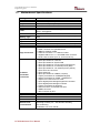
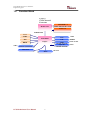
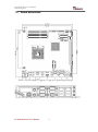
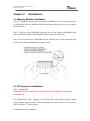
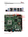
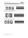
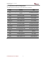
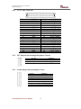
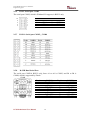
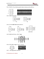
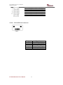
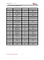
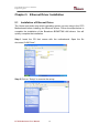
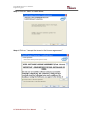
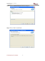
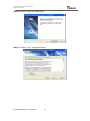
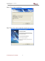
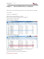
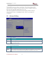
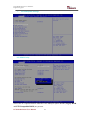
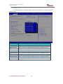
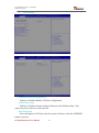
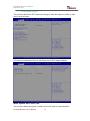
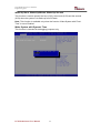
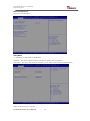
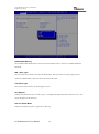
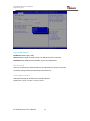
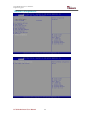
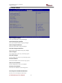
1
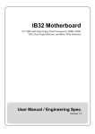
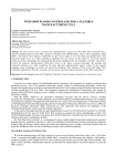
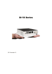
IC70 Motherboard Mini-ITX Fan SBC with Intel® CoreTM i5/i7/Celeron® Processor, VGA, LVDS, Giga Ethernet, Mini-PCIe and PCIE x 16 Slot User Manual / Engineering Spec. Version 1.2 IC70 Motherboard User Manual / Engineering Spec. FCC Statement This device complies with part 15 FCC rules. Operation is subject to the following two conditions: This device may not cause harmful interference. This device must accept any interference received including interference that may cause undesired operation. This equipment has been tested and found to comply with the limits for a class "a" digital device, pursuant to part 15 of the FCC rules. These limits are designed to provide reasonable protection against harmful interference when the equipment is operated in a commercial environment. This equipment generates, uses, and can radiate radio frequency energy and, if not installed and used in accordance with the instruction manual, may cause harmful interference to radio communications. Operation of this equipment in a residential area is likely to cause harmful interference in which case the user will be required to correct the interference at him own expense. IC70 Motherboard User Manual II IC70 Motherboard User Manual / Engineering Spec. Copyright Notice ALL RIGHTS RESERVED. No part of this document may be reproduced, copied, translated, or transmitted in any form or by any means, electronic or mechanical, for any purpose, without the prior written permission of the original manufacturer. Trademark Acknowledgement Brand and product names are trademarks or registered trademarks of their respective owners. Disclaimer We. reserves the right to make changes, without notice, to any product, including circuits and/or software described or contained in this manual in order to improve design and/or performance. We assume no responsibility or liability for the use of the described product(s), conveys no license or title under any patent, copyright, or masks work rights to these products, and makes no representations or warranties that these products are free from patent, copyright, or mask work right infringement, unless otherwise specified. Applications that are described in this manual are for illustration purposes only. We Communication Inc. makes no representation or warranty that such application will be suitable for the specified use without further testing or modification. Warranty We warrant that each of its products will be free from material and workmanship defects for a period of one year from the invoice date. If the customer discovers a defect, We will, at its option, repair or replace the defective product at no charge to the customer, provided it is returned during the warranty period of one year, with transportation charges prepaid. The returned product must be properly packaged in its original packaging to obtain warranty service. If the serial number and the product shipping data differ by over 30 days, the in-warranty service will be made according to the shipping date. In the serial numbers the third and fourth two digits give the year of manufacture, and the fifth digit means the month (e. g., with A for October, B for November and C for December). For example, the serial number 1W07Axxxxxxxx means October of year 2007. IC70 Motherboard User Manual III IC70 Motherboard User Manual / Engineering Spec. Packing List Before using this Motherboard, please make sure that all the items listed below are present in your package: IC70 Motherboard IC70 SBC User Manual HDD SATA Cable User’s Manual & Driver CD If any of these items are missing or damaged, contact your distributor or sales representative immediately. Customer Service We provide service guide for any problem as follow steps: Please contact with your distributor, sales representative, or our customer service center for technical support if you need additional assistance. You may have the following information ready before you call: Product serial number Peripheral attachments Software (OS, version, application software, etc.) Description of complete problem The exact wording of any error messages In addition, free technical support is available from our engineers every business day. We are always ready to give advice on application requirements or specific information on the installation and operation of any of our products. Please do not hesitate to call or e-mail us. IC70 Motherboard User Manual IV IC70 Motherboard User Manual / Engineering Spec. Safety Precautions Warning! Always completely disconnect the power cord from your chassis whenever you work with the hardware. Do not make connections while the power is on. Sensitive electronic components can be damaged by sudden power surges. Only experienced electronic personnel should open the PC chassis. Caution! Always ground yourself to remove any static charge before touching the CPU card. Modern electronic devices are very sensitive to static electric charges. As a safety precaution, use a grounding wrist strap at all times. Place all electronic components in a static-dissipative surface or static-shielded bag when they are not in the chassis. IC70 Motherboard User Manual V IC70 Motherboard User Manual / Engineering Spec. Safety and Warranty 1. 2. 3. 4. 5. 6. 7. 8. 9. 10. 11. 12. 13. 14. 15. Please read these safety instructions carefully. Please keep this user's manual for later reference. Please disconnect this equipment from any AC outlet before cleaning. Do not use liquid or spray detergents for cleaning. Use a damp cloth. For pluggable equipment, the power outlet must be installed near the equipment and must be easily accessible. Keep this equipment away from humidity. Put this equipment on a reliable surface during installation. Dropping it or letting it fall could cause damage. The openings on the enclosure are for air convection. Protect the equipment from overheating. DO NOT COVER THE OPENINGS. Make sure the voltage of the power source is correct before connecting the equipment to the power outlet. Position the power cord so that people cannot step on it. Do not place anything over the power cord. All cautions and warnings on the equipment should be noted. If the equipment is not used for a long time, disconnect it from the power source to avoid damage by transient over-voltage. Never pour any liquid into an opening. This could cause fire or electrical shock. Never open the equipment. For safety reasons, only qualified service personnel should open the equipment. If any of the following situations arises, get the equipment checked by service personnel: A. The power cord or plug is damaged. B. Liquid has penetrated into the equipment. C. The equipment has been exposed to moisture. D. The equipment does not work well, or you cannot get it to work according to the user’s manual. E. The equipment has been dropped and damaged. F. The equipment has obvious signs of breakage. Do not leave this equipment in an uncontrolled environment where the storage temperature is below -20° C (-4°F) or above 60° C (140° F). It may damage the equipment. IC70 Motherboard User Manual VI IC70 Motherboard User Manual / Engineering Spec. Revision History Version Date Note Author 1.0 2011.07.15 Initial Draft Henry Hsu 1.1 2011.12.09 Henry Hsu 1.2 2015.05.08 Add COM port driver install Revise Pin definition IC70 Motherboard User Manual VII Jimmy Chen IC70 Motherboard User Manual / Engineering Spec. Contents CHAPTER 1 1.1 1.2 1.3 1.4 1.5 CHAPTER 2 GENERAL INFORMATION .......................................1 INTRODUCTION ............................................................................... 1 FEATURE ......................................................................................... 1 MOTHERBOARD SPECIFICATIONS .................................................... 2 FUNCTION BLOCK ........................................................................... 3 BOARD DIMENSIONS........................................................................ 4 INSTALLATIONS.........................................................6 2.1 MEMORY MODULE INSTALLATION .................................................. 6 2.2 2.3 2.4 2.5 I/O EQUIPMENT INSTALLATION ....................................................... 6 JUMPERS AND CONNECTORS ........................................................... 8 JUMPER SETTING............................................................................. 9 CONNECTORS AND PIN ASSIGNMENT ............................................ 11 CHAPTER 3 3.1 CHAPTER 4 4.1 CHAPTER 5 5.1 CHAPTER 6 6.1 GRAPHIC DRIVER INSTALLATION ....................22 INSTALLATION OF GRAPHIC DRIVER.............................................. 22 CHIPSET DRIVER INSTALLATION .....................26 INSTALLATION OF CHIPSET DRIVER ............................................... 26 ETHERNET DRIVER INSTALLATION .................30 INSTALLATION OF ETHERNET DRIVER ........................................... 30 AUDIO DRIVER INSTALLATION..........................35 INSTALLATION OF AUDIO DRIVER ................................................. 35 CHAPTER 7 FINTEK COM PORT DRIVER INSTALLATION .41 CHAPTER 8 AMI BIOS SETUP ......................................................45 8.1 8.2 8.3 STARTING SETUP ........................................................................... 45 ADVANCED SETTING ..................................................................... 46 CHIPSET SETTING .......................................................................... 66 8.4 8.5 8.5 BOOT ............................................................................................ 71 SECURITY...................................................................................... 72 SAVE & EXIT ................................................................................. 73 CHAPTER 9 9.1 SERVICES / UPDATES .............................................74 IC70 OFFICIAL WEBSITE ............................................................... 74 IC70 Motherboard User Manual VIII IC70 Motherboard User Manual / Engineering Spec. 9.2 COMPANY INFORMATION ............................................................... 74 IC70 Motherboard User Manual IX General Information CHAPTER IC70 Motherboard User Manual / Engineering Spec. 1 This chapter includes IC70 Motherboard background information. Sections include: Introduction Feature Motherboard Specification Function Block Board Dimensions IC70 Motherboard User Manual 1 IC70 Motherboard User Manual / Engineering Spec. Chapter 1 1.1 General Information Introduction IC70 SBC is equipped with Intel HM55 Chipset which designed with Intel’s mobile platform. Intel’s HM55 platform delivers the performance and high scalability cutting-edge embedded computing application. In peripheral connectivity, IC70 SBC with one PCIE x 16 and two Mini-PCIE slot, two SATA connectors, and eight Hi-Speed USB connectors. Thus, IC70 SBC is designed to satisfy most of the applications in the industrial computer market, such as Gaming, POS, KIOSK, Industrial Automation, and Programmable Control System. It is a compact design to meet the demanding performance requirements of today’s business and industrial applications. 1.2 Feature Mini-ITX Form Factor ( 170mm x 170mm) Support Intel® CoreTM i7/i5/Celeron® Processor System memory up to 8GB DDR3 800/1066, 2 x SO-DIMM Intel® 5 series Chipset (HM55) Integrated Gfx Gen5.75, supports DirectX 10 and OpenGL 2.1 Dual Gigabit Ethernet 1 x PCIEx16 slot, 2 x Mini-PCIE, 6 x COM, 8 x USB2.0 HDMI/DVI interface, supports max. resolution 1920 x 1200 @60Hz IC70 Motherboard User Manual 1 IC70 Motherboard User Manual / Engineering Spec. 1.3 Motherboard Specifications CPU Type CPU FSB CPU Socket Chipset BIOS VGA LVDS LAN Memory Type Super I/O Keyboard/Mouse Sound USB Edge Connectors On Board Pin-Header Connectors Power Connector Expansion Slots Form Factor Dimensions Mechanical & environmental Intel® CoreTM i7/i5/Celeron® Processor 1066/800 MHz Intel Socket G1(rPGA989) Intel® 5 series Chipset (HM55) AMI UEFI BIOS Analog monitor resolution up to 2048 x 1536 @75Hz Dual-channel 18/24-bit LVDS, supports max resolution 1600 x 1200 @60Hz Dual Broadcom BCM57780 PCIe GbE LAN controller Two DDR3 1066/800MHz SO-DIMM supported ( max. 8GB) Fintek F81865 2 x PS/2 Keyboard/Mouse connectors Realtek ALC886 HD codec (Line-in, Line out, Mic-in) 8 ports, USB 2.0 (4 x USB Connector, 4 x USB pin-header ) 1 x +12V DC-IN Jack 2 x PS/2 connector for keyboard/mouse 2 x DB9 for COM3 & COM4 1 x VGA out connector + 1 x DB9 for COM1 2 x Gigabit LAN RJ-45 + 1 x dual USB stack connector 1 x Audio Jack for Audio (Line-in, Line-Out, Mic-in) 1 x 10pins pin-header for Front Panel(2x5) 1 x 3pins pin-header for CPU Fan 1 x 3pins pin-header for System FAN 1 x 8pins pin-header for 5V/12V external power(2x4) 1 x 2pins pin-header for 5V external power (Red) 1 x 2pins pin-header for 12V external power (Yellow) 1 x 4pins ATX 12V connector 2 x 2pins Audio out 2 x 8pins pin-header for USB 5/6, 7/8(2x4) 1 x 10pins pin-header for COM2(RS232)(2x5) 1 x 20pins pin-header for COM5、COM6(2x10) 1 x 40pins DF13 Connector for LVDS 1 x 3pins digital panel backlight brightness controller 1 x 7pins digital panel backlight controller 1 x 10pins pin-header for DIO(2x5) 2 x SATA connector for SATAI/II 3.0 Gb/s 1 x HDMI connecter 1 x DVI connecter by FFC Input: 4-pin ATX 12V Power input 1 x PCIEx16, 2 x Mini-PCIE Mini-ITX 170mm x 170mm Operating temperature: 0 deg. C to 60 deg. C Operating Humidity: 30 ~ 90% Relative humidity, non-condensing Certification: CE, FCC, RoHS IC70 Motherboard User Manual 2 IC70 Motherboard User Manual / Engineering Spec. 1.4 Function Block CoreTM i7/i5/Celeron® Processor Mobile CPU SO-DIMM x 2 DDR3 800/1066 Max.8GB PCIE x 16 FSB 800/1066 VGA LVDS Intel HM55 DVI HDMI 3GB/s Chipset SATA II 1, SATAII 2 Mini PCIe BIOS Realtek ALC655 IC70 Motherboard User Manual 3 LAN 1GB/s USB 480MB/s Audio Realtek ALC655 Super IO Realtek ALC655 AMI UEFI Realtek ALC886 F81865 IC70 Motherboard User Manual / Engineering Spec. 1.5 Board dimensions IC70 Motherboard User Manual 4 Installations CHAPTER IC70 Motherboard User Manual / Engineering Spec. 2 This chapter provides information on how to use the jumps and connectors on IC70 Motherboard. The Sections include: Memory Module Installation I / O Equipment Installation Jumpers and Connectors Jumpers Setting Connectors and Pin Assignment IC70 Motherboard User Manual 5 IC70 Motherboard User Manual / Engineering Spec. Chapter 2 Installations 2.1 Memory Module Installation The IC70 Motherboard provides two 204-pin SODIMM slot. The socket supports up to 8GB DDR3 800/1066 SDRAM. When installing the Memory device, please follow the steps below: Step.1. Firmly insert the SODIMM at an angle into its slot. Align the SODIMM on the slot such that the notch on the SODIMM matches the break on the slot. Step.2. Press downwards on SODIMM until the retaining clips at both ends fully snap back in place and the SODIMM is properly seated. 2.2 I/O Equipment Installation 2.2.1 12V DC-IN *Without power/reset OSD, short circuit pin 5 and 6 together to boot up the motherboard. The Motherboard allows plugging 12V DC-IN jack on the board without another power module converter under power consumption by Intel Socket G1 processor in HM55 with Intel® 5 series chipset. IC70 Motherboard User Manual 6 IC70 Motherboard User Manual / Engineering Spec. 2.2.2 PS/2 Keyboard and PS/2 Mouse The Motherboard provides two PS/2 interface. The PS/2 connector supports Keyboard and Mouse. In other cases, especially in embedded applications, a mouse is not used. Therefore, the BIOS standard setup menu allows you to select* “All, But Keyboard” under the “Halt On”. This allows no-keyboard operation in embedded system applications without the system halting under POST. 2.2.3 Serial COM ports Three RS-232 connectors build in the rear I/O. Fourth optional COM ports support RS-232. When an optional touch-screen is ordered with PPC, serial com port can connect to a serial or an optional touch-screen. One optional COM port supports RS232/422/485 choice through jumper setting. 2.2.4 Internal VGA The Motherboard has one VGA port that can be connected to an external CRT/ LCD monitor. Use VGA cable to connect to an external CRT / LCD monitor, and connect the power cable to the outlet. The VGA connector is a standard 15-pin D-SUB connector. 2.2.5 Ethernet interface The Motherboard is equipped with Broadcom BCM57780 chipset which is fully compliant with the PCI 10/100/1000 Mbps Ethernet protocol compatible. It is supported by major network operating systems. The Ethernet ports provide two standard RJ-45 jacks. 2.2.6 USB ports Eight USB devices (four with pin headers) may be connected to the system though an adapter cable. Various adapters may come with USB ports. USB usually connect the external system to the system. The USB ports support hot plug-in connection. Whatever, you should install the device driver before you use the device. 2.2.7 Audio Jack ( Pin-header) The Audio 5.1 channel capabilities are provided by a Realtek ALC886 chipset supporting digital audio outputs. The audio interface includes Mic-in,: line-in and line-out. IC70 Motherboard User Manual 7 IC70 Motherboard User Manual / Engineering Spec. 2.3 Jumpers and Connectors TOP COM4 DC Jack PS/2 COM1 COM3 SODIMM2 SODIMM1 VGA 5V CN2 12V HDD PWR LAN1 LAN2 USB JP7 JP1 USB1,2 Audio Jack CON3 SATA1,2 PANEL1 CON7 J2 CON8 CN6 CON9 PCIEx16 NB_FAN1 CPU_FAN2 J1 CN22 CON2 CN3 CON11 ATX12V J4,J5 JP3 IC70 Motherboard User Manual JP4 8 IC70 Motherboard User Manual / Engineering Spec. 2.4 Jumper Setting A pair of needle-nose pliers may be helpful when working with jumpers. If you have any doubts about the best hardware configuration for your application, contact your local distributor or sales representative before you make any changes. Generally, you simply need a standard cable to make most connections. The jumper setting diagram is as below. If a jumper shorts pin 1 and pin 2, the setting diagram is shown as the right one. Normal Clear CMOS 1 1 2 2 3 3 The following tables list the function of each of the board's jumpers. Label Function Note JP1 Clear CMOS 3x1 header , pitch 2.0mm JP3 RS232 / RS422 / RS485 Selector 2x3 header , pitch 2.0mm JP4 RS232 / RS422 / RS485 Selector 3x4 header , pitch 2.0mm CON9 LVDS VOLTAGE 2x3 header , pitch 2.0mm 2.4.1 JP1: Clear CMOS User must make sure the power supply to turn off the power supply before setting Clear CMOS. Users remember to setting jumper back to Normal before turning on the power supply. Default: 2 short 3. Clear CMOS Normal 1 1 2 2 3 3 IC70 Motherboard User Manual Pin No. 1 Short 2 2 Short 3 9 Functions Clear CMOS Normal IC70 Motherboard User Manual / Engineering Spec. JP3 : COM1 RS232 / RS422 / RS485 Function Selector The jumper can be configured to operate COM1 in RS-232/422/485 mode. And the setting must be cooperated with the 2.4.2 settings. Default 1 short 2. RS232 RS422 RS485 1 2 1 2 1 2 3 4 3 4 3 4 5 6 5 6 5 6 Pin No. 1 Short 2 3 Short 4 5 Short 6 Functions RS232 RS422 RS485 2.4.2 JP4: RS232 / RS422 / RS485 Selector The jumper can be configured to operate COM1 in RS-232/422/485 mode. And the setting must be cooperated with JP3 settings. RS232 RS422/485 1 3 1 3 4 6 4 6 7 9 7 9 10 12 10 RS232 1-2 4-5 7-8 10-11 12 RS422/485 2-3 5-6 8-9 11-12 2.4.3 CON9: LCD Panel Voltage Select CON9 can be configured to operate in 3.3Volts / 5Volts / 12Volts mode. 3.3Volts 5Volts 12Volts 1 2 1 2 1 2 3 4 3 4 3 4 5 6 5 6 5 6 IC70 Motherboard User Manual Pin No. 1 Short 2 3 Short 4 5 Short 6 10 Functions 3.3Volts Selected 5Volts Selected 12Volts Selected IC70 Motherboard User Manual / Engineering Spec. 2.5 Connectors and Pin Assignment The table below lists the function of each of the board’s connectors. Label Function Note CON7 DF13-40DP-1.25V 3x1 header, pitch 2.54mm CON8 LVDS LCD Output Connector Digital Panel Backlight Brightness Control Inverter Connecter CON3 Serial port COM2 10pin COM port CON11 Serial port COM5,6 20 Pin COM port USB USB PIN HEADER 4x2 Pin Header FAN1_NB FAN CONNECTOR 3x1 Pin Header FAN2_CPU FAN CONNECTOR 3x1 Pin Header PANEL1 System Function Connector 5x2 header ,pitch 2.0mm J4 Front Audio (Right) 1x2 header ,pitch 2.54mm J5 Front Audio (Left) 1x2 header ,pitch 2.54mm 12V (Yellow) 12V External Power 2x1 header, pitch 2.54mm 5V(Red) 5V External Power 2x1 header, pitch 2.54mm HDD PWR 5V/12V External Power 4x2 header ,pitch 2.54mm CON2 Digital I/O 10 pin Digital I/O function CN2 Mini-PCIE Half size CN3 Mini-PCIE Full size CN22 SIM card connector 6 pin Header J2 DVI FFC 18 pin FFC CN6 HDMI CONNECTOR 19 pin HDMI port ATX12V 12V DC Connector 2x2 Pin Connecter JP7 IC70 Motherboard User Manual 11 7x1 header, pitch 2.54mm IC70 Motherboard User Manual / Engineering Spec. 2.5.1 CN7: LVDS Connector Pin No. 1 3 5 7 9 11 13 15 17 19 21 23 25 27 29 31 33 35 37 39 SYMBOL LCDVDD LCDVDD LCDVDD GND GND GND GND GND GND GND GND GND GND GND GND GND GND GND GND GND Pin No. 2 4 6 8 10 12 14 16 18 20 22 24 26 28 30 32 34 36 38 40 SYMBOL LVDS_TXL0N LVDS_ TXL0P LVDS_ TXL1N LVDS_ TXL1P LVDS_ TXL2N LVDS_ TXL2P LVDS_TXLCKN LCDS_ TXLCKP LVDS_ TXL3N LVDS_ TXL3P LVDS_TXU0N LVDS_ TXU0P LVDS_ TXU1N LVDS_ TXU1P LVDS_ TXU2N LVDS_ TXU2P LVDS_TXUCKN LVDS_TXUCKP LVDS_TXU3N LVDS_TXU3P 2.5.2 JP7: Digital Panel Backlight Brightness Control Pin No. 1 2 3 SYMBOL VCC(5V) Black Light Control GND 2.5.3 CON8: Digital Panel Backlight Control Pin No. 1 2 3 4 5 6 7 IC70 Motherboard User Manual SYMBOL +12V +12V +12V GND Black Light Control GND Black Light EN 5V 12 IC70 Motherboard User Manual / Engineering Spec. 2.5.4 PSKBM1: PS2 Keyboard/Mouse Connector Pin No. 1 2 3 4 5 6 PS/2 Keyboard SYMBOL KDATA NC1 Ground 5V KBCLK NC2 Pin No. 7 8 9 10 15 16 PS/2 Mouse SYMBOL MDATA NC3 Ground 5V MSCLK NC4 2.5.5 D-SUB Dual Output The serial port COM1, which is option for RS232 / RS422 / RS485, is the Winbond I/O serial port. COM1 C1 Up: 9(Male) C6 V1 V6 V11 Down: 15(Female) VGA Pin No. C1 C2 C3 C4 C5 C6 C7 C8 C9 SYMBOL DCD4/485TXRXSRD4/485TXRX+ STD4/422RX+ DTR4/422RXGND NDSRA NRTSA NCTSA NRIA IC70 Motherboard User Manual 13 Pin No. V1 V2 V3 V4 V5 V6 V7 V8 V9 V10 V11 V12 V13 V14 V15 SYMBOL R G B NA GND GND GND GND LVGA5V GND NA DDC_DATA CRT_HS CRT_VS DDC_CLK IC70 Motherboard User Manual / Engineering Spec. 2.5.6 CON3: Serial port COM2 The serial port COM2, which is Winbond I/O support, is RS232 only. 10 8 6 4 2 9 7 5 3 1 Pin 10 8 6 4 2 SYMBOL GND NRI1A NCTS1A NRTS1A NDSR1A Pin 9 7 5 3 1 SYMBOL GND NDTR1A NTXD1A NRXD1A NDCD1A 2.5.7 CON11: Serial port COM5、COM6 2.5.8 D-SUB Dual Serial Port The serial port COM3/4, RS232 only, from A1 to A9 is COM3, and B1 to B9 is COM4, which is supported by Fintek. COM4 Pin No. A1 A2 A3 A4 A5 A6 A7 A8 A9 B1 B6 A1 A6 SYMBOL FK_NDCD1 FK_NSIN1 FK_NSOUT1 FK_NDTR1 GND FK_NDSR1 FK_NRTS1 FK_NCTS1 FK_NRI1 COM3 IC70 Motherboard User Manual 14 Pin No. B1 B2 B3 B4 B5 B6 B7 B8 B9 SYMBOL FK_NDCD2 FK_NSIN2 FK_NSOUT2 FK_NDTR2 GND FK_NDSR2 FK_NRTS2 FK_NCTS2 FK_NRI2 IC70 Motherboard User Manual / Engineering Spec. 2.5.9 AUDIO401: Audio Jack ( Pin-header ) Color Blue Green Pink C0~C4 B1~B4 A1~A4 Signal Line In Line Out Microphone In Pin-Header Line in Line out Mic in 2.5.10 USB: USB PIN HEADER 2 1 4 3 6 5 8 7 USB1 Pin SYMBOL Pin SYMBOL 2 USB 5V 1 USB 5V 4 USB_DATA13 USB_DATA06 USB_DATA1+ 5 USB_DATA0+ 8 GND 7 GND 2.5.11 FAN1_NB/FAN2_CPU: FAN CONNECTOR FAN1_NB IC70 Motherboard User Manual FAN2_CPU 15 IC70 Motherboard User Manual / Engineering Spec. 2.5.12 PANEL1: Front Panel System Function Connector (Power/Reset) 2 4 6 8 10 Pin 2 4 6 8 10 1 3 5 7 9 SYMBOL HD_LED+ HD_LEDRT_BT1 RT_BT2 5VSB Pin 1 3 5 7 9 SYMBOL PW_LED+ PW_LEDPW_BT1 PW_BT2 RSEV 2.5.13 J4/J5: Front Audio J4 J5 2.5.14 5V/12V/HDD PWR: External Power Yellow 12V Red 5V HDD PWR 2.5.15 PWIN1: DC Jack ( +12V) / Input 2.5.16 ATX_PWR / Input: 12V DC Connector Pin 1 2 3 4 SYMBOL Ground Ground +12V +12V 2.5.17 : CN2: Digital I/O Connector IC70 Motherboard User Manual 16 IC70 Motherboard User Manual / Engineering Spec. 2 4 6 8 10 1 3 5 7 9 Pin 2 4 6 8 10 SYMBOL 5V Out1 Out0 IN1 IN0 Pin 1 3 5 7 9 SYMBOL GND Out3 Out2 IN3 IN2 2.5.18 : CN22:SIM card connector CN22 Pin Number 1 2 3 4 5 6 IC70 Motherboard User Manual 17 Signal Name VREG_USIM MSM_USIM_RESET MSM_USIM_CLK GND MSM_USIM_VPP MSM_USIM_DATA IC70 Motherboard User Manual / Engineering Spec. 2.5.19 : CN2: Half Size Mini-PCIE slot Pin Number Signal Name Pin Number Signal Name 2 3.3V_MINIPCIE1 1 PCIE_WAKE# 4 GND 3 NA 6 +V1.5S 5 NA 8 VREG_USIM 7 CLK_SLOT4_OE# 10 NA 9 GND 12 NA 11 CLK_PCIE_SLOT4_N 14 NA 13 CLK_PCIE_SLOT4_P 16 NA 15 GND 18 GND 17 NA 20 WLAN-RFON2 19 NA 22 BUF_PLT_RST2# 21 GND 24 +V3.3A 23 PCIE_RXN3_SLOT4 26 GND 25 PCIE_RXP3_SLOT4 28 +V1.5S 27 GND 30 SMB_CLK 29 GND 32 SMB_DATA 31 PCIE_TXN3_SLOT4 34 GND 33 PCIE_TXP3_SLOT4 36 USB_PN5 35 GND 38 USB_PP5 37 GND 40 GND 39 3.3V_MINIPCIE1 42 NA 41 3.3V_MINIPCIE1 44 NA 43 GND 46 NA 45 NA 48 NA 47 NA 50 GND 49 NA 52 3.3V_MINIPCIE1 51 NA m2 GND m1 GND IC70 Motherboard User Manual 18 IC70 Motherboard User Manual / Engineering Spec. 2.5.20 : CN3: Full Size 3.5G Module Pin Number Signal Name Pin Number Signal Name 2 3.3V_MINIPCIE1 1 PCIE_WAKE# 4 GND 3 NA 6 +V1.5S 5 NA 8 VREG_USIM 7 CLK_SLOT3_OE# 10 MSM_USIM_DATA 9 GND 12 MSM_USIM_CLK 11 CLK_PCIE_SLOT3_N 14 MSM_USIM_RESET 13 CLK_PCIE_SLOT3_P 16 MSM_USIM_VPP 15 GND 18 GND 17 NA 20 WLAN-RFON1 19 NA 22 BUF_PLT_RST2# 21 GND 24 +V3.3A 23 PCIE_RXN3_SLOT3 26 GND 25 PCIE_RXP3_SLOT3 28 +V1.5S 27 GND 30 SMB_CLK 29 GND 32 SMB_DATA 31 PCIE_TXN3_SLOT3 34 GND 33 PCIE_TXP3_SLOT3 36 USB_PN4 35 GND 38 USB_PP4 37 GND 40 GND 39 3.3V_MINIPCIE1 42 NA 41 3.3V_MINIPCIE1 44 NA 43 GND 46 NA 45 NA 48 NA 47 NA 50 GND 49 NA 52 3.3V_MINIPCIE1 51 NA m2 GND m1 GND IC70 Motherboard User Manual 19 IC70 Motherboard User Manual / Engineering Spec. 2.5.21 : J2: DVI FFC Pin Number Signal Name Pin Number Signal Name 2 DVIC_TMDS0 1 GND 4 GND 3 DVIC_TMDS0+ 6 DVI_DDC_DATA 5 DVI_DDC_CLK 8 DVIC_TMDS1 7 GND 10 GND 9 DVIC_TMDS1+ 12 DVIC_TMDS2+ 11 DVIC_TMDS2- 14 DVIC_CLK+ 13 GND 16 DVI_HPD2 15 DVIC_CLK 18 +5VS 17 +5VS Pin Number Signal Name Pin Number Signal Name 2 GND 1 HDMIB_TMDS0+ 4 HDMIB_TMDS1+ 3 HDMIB_TMDS0- 6 HDMIB_TMDS1- 5 GND 8 GND 7 HDMIB_TMDS2+ 10 HDMIB_CLK+ 9 HDMIB_TMDS2- 12 HDMIB_CLK- 11 GND 14 RESERVED 13 GND 16 HDMI_DDC_DATA 15 HDMI_DDC_CLK 18 5V_HDMI 17 GND 20 NA 19 HDMI_HPD1 2.5.22 :CN6: HDMI IC70 Motherboard User Manual 20 CHAPTER IC70 Motherboard User Manual / Engineering Spec. 3 Graphic Driver Installation This chapter offers information on the chipset software Installation utility Installation of Graphic Driver IC70 Motherboard User Manual 21 IC70 Motherboard User Manual / Engineering Spec. Chapter 3 Graphic Driver Installation 3.1 Installation of Graphic Driver IC70 Motherboard is equipped with Intel GM45 / ICH9M-E Companion Device. The Intel Graphic Drivers should be installed first, and it will enable “Video Controller (VGA compatible). Follow the instructions below to complete the installation. You will quickly complete the installation. Step.1. Insert the CD that comes with the Motherboard. Open the file document “Graphic Driver “. Step.2. Click on “winxp_14428” to execute the setup. IC70 Motherboard User Manual 22 IC70 Motherboard User Manual / Engineering Spec. Step.3. Click on “Next “ to install Driver. Step.4. Click on “Next “ to install Driver. IC70 Motherboard User Manual 23 IC70 Motherboard User Manual / Engineering Spec. Step.5. Click on “Yes “ to agree License. Step.7. Click on “Yes, I want to restart this computer now“ to go on. IC70 Motherboard User Manual 24 CHAPTER IC70 Motherboard User Manual / Engineering Spec. 4 Chipset Driver Installation This chapter offers information on the chipset software Installation utility Installation of Chipset Driver IC70 Motherboard User Manual 25 IC70 Motherboard User Manual / Engineering Spec. Chapter 4 Chipset Driver Installation 4.1 Installation of Chipset Driver Setp.1. Insert the CD that comes with the motherboard. Open the file document “Chipset Driver”. Setp.2. Click on “Setup“ to install driver. IC70 Motherboard User Manual 26 IC70 Motherboard User Manual / Engineering Spec. Setp.3. Click on “Next“ to install driver. Setp.4. Click on “Yes “ to agree License IC70 Motherboard User Manual 27 IC70 Motherboard User Manual / Engineering Spec. Setp.5. Click on “Next“ to install driver. Step.7. Click on “Yes, I want to restart this computer now“ to go on. IC70 Motherboard User Manual 28 CHAPTER IC70 Motherboard User Manual / Engineering Spec. 5 Ethernet Driver Installation This chapter offers information on the Ethernet software installation utility. Sections include: Installation of Ethernet Driver IC70 Motherboard User Manual 29 IC70 Motherboard User Manual / Engineering Spec. Chapter 5 5.1 Ethernet Driver Installation Installation of Ethernet Driver The Users must make sure which operating system you are using in the IC70 Motherboard before installing the Ethernet drivers. Follow the steps below to complete the installation of the Broadcom BCM57780 LAN drivers. You will quickly complete the installation. Step.1. Insert the CD that comes with the motherboard. Open the file document “LAN Driver”. Step.2 Click on “Setup” to execute the setup. IC70 Motherboard User Manual 30 IC70 Motherboard User Manual / Engineering Spec. Step.3. Click on “Next“ to install driver. Step.4. Click on “I accept the terms in the license agreement.” IC70 Motherboard User Manual 31 IC70 Motherboard User Manual / Engineering Spec. Setp.5. Click on “Advanced Network Services“ and go on. Setp.6. Click on “Next“ to install driver. IC70 Motherboard User Manual 32 IC70 Motherboard User Manual / Engineering Spec. Setp.7. Click on “Finish“. IC70 Motherboard User Manual 33 CHAPTER IC70 Motherboard User Manual / Engineering Spec. 6 Audio Driver Installation This chapter offers information on the Audio software installation utility. Sections include: Installation of Audio Driver IC70 Motherboard User Manual 34 IC70 Motherboard User Manual / Engineering Spec. Chapter 6 Audio Driver Installation 6.1 Installation of Audio Driver The users must make sure which operating system you are using in the IC70 Motherboard before installing the Audio drivers. Follow the steps below to complete the installation of the VIA VT1708B Audio drivers. You will quickly complete the installation. Step.1. Insert the CD that comes with the motherboard. Open the file “Audio driver” and click on “Setup” to execute the setup. IC70 Motherboard User Manual 35 IC70 Motherboard User Manual / Engineering Spec. Step.2. Click on “Next“ to install driver. Step.3. Click on “Yes “ to agree License IC70 Motherboard User Manual 36 IC70 Motherboard User Manual / Engineering Spec. Step.4. Click on “Next“ to install driver. Step.5. Click on “Next“ to install driver. IC70 Motherboard User Manual 37 IC70 Motherboard User Manual / Engineering Spec. Step.6. Click on “Next“ to install driver. Step.7 Click on “Yes, I want to restart this computer now“ to go on. IC70 Motherboard User Manual 38 IC70 Motherboard User Manual / Engineering Spec. Step.9 After restart computer, cliick on “HD ADeck “ to set up Line in/Mic in. Step.10 Select ” Analog to the Line out “ and click “ Next page” Step.11 Select ” Analog to the Line out “ and move the bar. IC70 Motherboard User Manual 39 CHAPTER IC70 Motherboard User Manual / Engineering Spec. 7 Fintek COM Port Driver Installation This chapter describes the step by step method to install the Fintek COM port driver. IC70 Motherboard User Manual 40 IC70 Motherboard User Manual / Engineering Spec. Chapter 7 Fintek COM Port Driver Installation STEP 1.If the system is WIN7 please first do close UAC.(Refer following “Disabling User Account Control (UAC) in Windows 7”) STEP 2.Extract the Patch_0408.zip to a folder. STEP 3.Double-click batch file(patch.bat) will install driver. STEP 4.Check driver install success. Before the update or update fail. After the update and update success. STEP 5.You will need to restart your computer for driver install success. Type in this command from the Run menu: C:\Windows\System32\UserAccountControlSettings.exe or IC70 Motherboard User Manual 41 IC70 Motherboard User Manual / Engineering Spec. uac To turn off UAC, move the slider to the Never notify position, and then click OK. If you're prompted for an administrator password or confirmation, type the password or provide confirmation. IC70 Motherboard User Manual 42 IC70 Motherboard User Manual / Engineering Spec. To turn UAC back on, move the slider to choose when you want to be notified, and then click OK. If you're prompted for an administrator password or confirmation, type the password or provide confirmation. You will need to restart your computer for UAC to be turned off. IC70 Motherboard User Manual 43 CHAPTER IC70 Motherboard User Manual / Engineering Spec. 8 AMI BIOS Installation This chapter describes the different settings available in the AMI BIOS that comes with the board. This chapter offers information on the Award BIOS installation utility. Sections include: BIOS Setup Advanced BIOS Features Advanced Chipset Features Integrated Peripherals Power Management Setup PC Health Status Load Fail-Safe Defaults Load Optimized Defaults Set Supervisor/User Password Save & Exit Setup Exit Without Saving IC70 Motherboard User Manual 44 IC70 Motherboard User Manual / Engineering Spec. Chapter 8 8.1 AMI BIOS SETUP Starting Setup Your computer comes with a hardware configuration program called BIOS Setup that allows you to view and set system parameters. The BIOS (Basic Input / Output System) is a layer of software, called ‘firmware’, that translates instructions from software (such as the operating system) into instructions that the computer hardware can understand. The BIOS settings also identify installed devices and establish special features. ENTERING BIOS SETUP You can access the BIOS program just after you turn on your computer. Just press the DEL key when the following prompt appears: Press <DEL> to enter Setup. When you press <DEL> to enter BIOS Setup, the system interrupts the Power-On Self-Test (POST). When you first enter the BIOS Setup Utility, you will enter the Main setup screen. You can always return to the Main setup screen by selecting the Main tab. There are two Main Setup options. They are described in this section. The Main BIOS Setup screen is shown below. IC70 Motherboard User Manual 45 IC70 Motherboard User Manual / Engineering Spec. The Main BIOS setup screen has two main frames. The left frame displays all the options that can be configured. Grayed-out options cannot be configured; options in blue can be. The right frame displays the key leg- end. Above the key legend is an area reserved for a text message. When an option is selected in the left frame, it is highlighted in white. Often a text message will accompany it. 8.2 Advanced Setting Legacy OpROM SETTING DESCRIPTION Disabled Use this setting to ignore all PXE Option ROMs. Enabled Use this setting to load PXE Option ROMs. To limit the PXE support to particular devices, use the function Use device for PXE. Default: Disabled Launch Storage OpROM SETTING DESCRIPTION Disabled Use this setting to ignore all PXE Option ROMs. Enabled Use this setting to specify that legacy PCI option ROMs for PCI storage devices are to be loaded and executed, if found. Typical examples of PCI storage devices include SCSI or similar devices. Default: Enabled IC70 Motherboard User Manual 46 IC70 Motherboard User Manual / Engineering Spec. PCI Subsystem Settings PCI ROM Priority Selects the PCI Option ROM to launch in case Multiple Option ROMs (Legacy ROM and EFI Compatible ROM) are present. IC70 Motherboard User Manual 47 IC70 Motherboard User Manual / Engineering Spec. PCI Latency Timer Use this function to select the number of PCI bus clocks to be used for the PCI latency timer. SETTING DESCRIPTION 32 PCI Bus Clocks Use this setting to program the PCI latency timer to 32 PCI bus clocks. 64 PCI Bus Clocks Use this setting to program the PCI latency timer to 64 PCI bus clocks. 96 PCI Bus Clocks Use this setting to program the PCI latency timer to 96 PCI bus clocks. 128 PCI Bus Clocks Use this setting to program the PCI latency timer to 128 PCI bus clocks. 160 PCI Bus Clocks Use this setting to program the PCI latency timer to 160 PCI bus clocks. 192 PCI Bus Clocks Use this setting to program the PCI latency timer to 192 PCI bus clocks. 224 PCI Bus Clocks Use this setting to program the PCI latency timer to 224 PCI bus clocks. 248 PCI Bus Clocks Use this setting to program the PCI latency timer to 248 PCI bus clocks. Default: 32 PCI Bus Clocks IC70 Motherboard User Manual 48 IC70 Motherboard User Manual / Engineering Spec. VGA Palette Snoop VGA Palette Snoop: This filed controls the ability of a primary PCI VGA controller to share a common palette (when a snoop write cycles) with an ISA video card. Enables or Disables VGA Palette Registers Snooping. PERR# Generation Enables or Disables PCI Device to Generate PERR#. SERR# Generation Enables or Disables PCI Device to Generate SERR#. Relaxed Ordering Enables or Disables PCI Express Device Relaxed Ordering. Extended Tag If ENABLED allows Device to use 8-bit Tag field as a requester. No Snoop Enables or Disables PCI Express Device No Snoop option. Maximum Payload Set Maximum Payload of PCI Express Device or allow System BIOS to select the value. Maximum Read Request Launches (Enabled/Disabled) the boot option for legacy network devices. IC70 Motherboard User Manual 49 IC70 Motherboard User Manual / Engineering Spec. ASPM Support Set the ASPM Level: Force L0 – Force all links to L0 State AUTO – BIOS auto configure DISABLE – Disables ASPM Extended Synch If ENABLED allows generation of Extended Synchronization patterns. IC70 Motherboard User Manual 50 IC70 Motherboard User Manual / Engineering Spec. ACPI Settings Enabled ACPI Auto Configuration Enables or Disables BIOS ACPI Auto Configuration. Enable Hibernation Enables or Disables System ability to Hibernate (OS/S4 Sleep State). This option may be not effective with some OS. ACPI Sleep State Select the highest ACPI sleep state the system will enter, when the SUSPEND button is pressed. IC70 Motherboard User Manual 51 IC70 Motherboard User Manual / Engineering Spec. S5 RTC Wake Settings This function defines the RTC wake-up settings to allow the system to wake up from the S5 (soft off) state. This screen provides functions for specifying the S5 RTC Wake Settings. Wake System with Fixed Time This function allows the system to wake up from S5 state at a specified time. IC70 Motherboard User Manual 52 IC70 Motherboard User Manual / Engineering Spec. Wake-Up Hour, Wake-Up Minute, Wake-Up Second This function is used to specify the hour (0-23), the minute (0-59) and the second (0-59) when the system is to wake up from S5 state. Note: This function is available only when the function “Wake System with Fixed Time” is set to Enabled. Wake System with Dynamic Time This function is intended for debugging purposes only. IC70 Motherboard User Manual 53 IC70 Motherboard User Manual / Engineering Spec. CPU Configuration This section shows the CPU configuration parameters. Hyper-threading Enabled for Windows XP and Linux (OS optimized for Hyper-Threading Technology) and Disabled for other OS (OS not optimized for Hyper-Threading Technology). When Disabled, only one thread per enabled core is enabled. IC70 Motherboard User Manual 54 IC70 Motherboard User Manual / Engineering Spec. Active Processor Cores This field is used to enter the number of cores to enable in each processor package. Limit CPUID Maximum Disabled for Windows XP. Execute Disable Bit XD can prevent certain classes of malicious buffer overflow attacks when combined with a supporting OS (Windows Server 2003 SP1, Windows XP SP2, SuSE Linux 9.2, RedHat Enterprise 3 Update 3.) Hardware Prefetcher Turns on/off the MLC streamer prefetcher. Adjacent Cache Line Prefetch To turn on/off prefetching of adjacent cache lines. Intel Virtualization Technology When enabled, a VMM can utilize the additional hardware capabilities provided by Vanderpool Technology. Power Technology Enable the power management features. TDC Limit / TDP Limit Turbo-XE Mode Processor TDC Limit in 1/8 A granularity. 0 means using the factory-configured value. IC70 Motherboard User Manual 55 IC70 Motherboard User Manual / Engineering Spec. SATA Configuration SATA Devices Configuration. SATA Mode (1) IDE Mode. (2) AHCI Mode. (3) RAID Mode. IDE Mode:This option configures the Serial ATA drives as Parallel ATA storage devices. AHCI Mode:This option allows the Serial ATA devices to use AHCI (Advanced Host ControllerInterface). Serial-ATA Controller Enable / Disable Serial ATA Controller. IC70 Motherboard User Manual 56 IC70 Motherboard User Manual / Engineering Spec. Intel IGD SWSCI OpRegion IC70 Motherboard User Manual 57 IC70 Motherboard User Manual / Engineering Spec. DVMT/FIXED Memory Select DVMT/FIXED Mode Memory size used by Internal Graphics Device. Options are 128MB, 256MB and Maximum. IGD – Boot Type Select the Video Device which will be activated during POST. This has no effect if external graphics present. Options are VBIOS Default, CRT, LFP, CRT+LFP, EFP and CRT+EFP. LCD Panel Type Selects the LCD panel used by the internal graphics device. ALS Support Enabled or Disabled. Valid only for ACPI. Legacy = ALS Support through the IGD INT10 function. ACPI = ALS support through an ACPI ALS driver. Gfx Low Power Mode Enabled or Disabled. This option is applicable for SFF only. IC70 Motherboard User Manual 58 IC70 Motherboard User Manual / Engineering Spec. USB Configuration IC70 Motherboard User Manual 59 IC70 Motherboard User Manual / Engineering Spec. Legacy USB Support Enabled-Enables legacy USB. Auto-Disables support for legacy when no USB devices are connected. Disabled-Keeps USB devices available only for EFI applications. EHCI Hand-off This is a workaround for OSes that does not support EHCI hand-off. The EHCI ownership change should be claimed by the EHCI driver. Device Reset Timeout USB mass storage device Start Unit command timeout. Options are: 10 sec / 20 sec / 30 sec / 40 sec. IC70 Motherboard User Manual 60 IC70 Motherboard User Manual / Engineering Spec. Super IO Configuration Serial Port Configuration Set Parameters of Serial Ports. User can Enable/Disable the serial port and Select an optimal settings for the Super IO Device. IC70 Motherboard User Manual 61 IC70 Motherboard User Manual / Engineering Spec. Serial Port Enables or disables the serial port. Change Settings Selects the IO/IRQ setting of the I/O device. Power Failure Options are: Keep last state 、Bypass mode 、Always on 、Always off (default) IC70 Motherboard User Manual 62 IC70 Motherboard User Manual / Engineering Spec. HW Monitor Fan1/Fan2 Smart Fan Control This field enables or disables the smart fan feature. At a certain temperature, the fan starts turning. Once the temperature drops to a certain level, it stops turning again. IC70 Motherboard User Manual 63 IC70 Motherboard User Manual / Engineering Spec. Thermal Configuration IC70 Motherboard User Manual 64 IC70 Motherboard User Manual / Engineering Spec. ME SMBus Thermal Reporting Enable/Disable ME SMBus Thermal Reporting Configuration. MCH Temp Read MCH Temperature Read Enable. PCH Temp Read PCH Temperature Read Enable. CPU Energy Read CPU Energy Read Enable. CPU Temp Read CPU Temperature Read Enable. Alert Enable Lock Lock all Alert Enable settings. IC70 Motherboard User Manual 65 IC70 Motherboard User Manual / Engineering Spec. 8.3 Chipset Setting North Bridge IC70 Motherboard User Manual 66 IC70 Motherboard User Manual / Engineering Spec. Low MMIO Align Low MMIO resources align at 64MB/1024MB. Initiate Graphic Adapter Select which graphics controller to use as the primary boot device. Options are IGD, PCI/IGD, PCI/PEG, PEG/IGD, PEG/PCI and SG. Graphics Turbo IMON Current Graphics turbo IMON current values supported (14-31). VT-d VT-d Enable/Disable. PCI Express Compliance Mode PCI Express Compliance Mode Enable/Disable. PCI Express Port Options are Disabled, Enabled and Auto. IGD Memory IGD Share Memory Size. Options are Disable, 32M, 64M and 128M. PAVP Mode Select PAVP Mode used by Internal Graphics Device. Options are Disabled and Enabled. PEG Force Gen1 PCI Express Port Force Gen1. Options are Disabled and Enabled. IC70 Motherboard User Manual 67 IC70 Motherboard User Manual / Engineering Spec. South Bridge IC70 Motherboard User Manual 68 IC70 Motherboard User Manual / Engineering Spec. SMBus Controller SMBus Controller help. GbE Controller This is constantly enabled. Wake on LAN from S5 Wake on LAN from S5 help. Restore AC Power Loss Options are Power Off, Power On and Last State. SLP_S4 Assertion Stretch Enable Select a minimum assertion width of the SLP_S4# signal. Azalia HD Audio Enables or disables the Azalia HD audio. High Precision Timer Enables or disables the high precision event timer. PCI Express Ports Configuration Enable or Disable the PCI Express Ports in the Chipset. IC70 Motherboard User Manual 69 IC70 Motherboard User Manual / Engineering Spec. USB Configuration Enable/Disable All USB Devices, USB 2.0 (EHCI) Support and RMH Support. The setting of AUTO on RMH Support Enable RMH support on Ibex Peak B0 Stepping. All USB Devices Enables or disables all USB devices. EHCI Controller 1 and EHCI Controller 2 These fields are used to enable or disable Enhanced Host Controller Interface (USB 2.0). IC70 Motherboard User Manual 70 IC70 Motherboard User Manual / Engineering Spec. 8.4 Boot Quiet Boot Enables or disables the quiet boot function. Fast Boot Enables/Disables boot with initialization of a minimal set of devices required to launch active boot option. Has no effect for BBS boot options. Setup Prompt Timeout Number of seconds to wait for setup activation key. 65535(0xFFFF) means indefinite waiting. Bootup NumLock State This allows you to determine the default state of the numeric keypad. By default, the system boots up with NumLock on wherein the function of the numeric keypad is the number keys. When set to Off, the function of the numeric keypad is the arrow keys. GateA20 Active UPON REQUEST – GA20 can be disabled using BIOS services. ALWAYS – do not allow disabling GA20; this option is useful when any RT code is executed above 1MB. Option ROM Messages Set display mode for Option ROM. Options are Force BIOS and Keep Current. Boot Option #1、#2、#3 Selects the boot sequence of the device. Hard Drive BBS Priorities Set the order of the legacy devices in this group. IC70 Motherboard User Manual 71 IC70 Motherboard User Manual / Engineering Spec. 8.5 Security This section allows you to configure and improve your system and llows you to set up some system features according to your preference. Administrator Password Set Setup Administrator Password. User Password Set User Password. HDD 0: FUJITSU MHY2 Sets the HDD password. IC70 Motherboard User Manual 72 IC70 Motherboard User Manual / Engineering Spec. 8.5 Save & Exit Save Changes and Exit Exit system setup after saving the changes. Disacard Changes and Exit Exit system setup without saving any changes. Save Changes and Reset Reset the system after saving the changes. Discard Changes and Reset Reset system setup without saving any changes. Save Changes Save Changes done so far to any of the setup options. Discard Changes Discard Changes done so far to any of the setup options. Restore Defaults Restore/Load Defaults values for all the setup options. Save as User Defaults Save the changes done so far as User Defaults. Restore User Defaults Restore the User Defaults to all the setup options. Reset System with ME disable Mode ME will run into the temporary disable mode. IC70 Motherboard User Manual 73 IC70 Motherboard User Manual / Engineering Spec. Chapter 9 9.1 Services / Updates IC70 Official Website The relevant information about IC70 Products including the latest news and downloads will be presented in the website below: http://www.winmate.com.tw/BoxPc/EmbeddedSpec.asp?Prod=05_0124&Typeid=B0123010302 Please go there to obtain further details of IC70 Products. 9.2 Company Information Winmate Communication Inc. 9F, No.111-6, Shin- De Rd,. San- Chung City Taipei 241, Taiwan, R.O.C. Tel: 886-2-8511-0288 Fax: 886-2-8511-0211 Contact us: [email protected] Distributor and more products: Please refer to our website: www.winmate.com.tw IC70 Motherboard User Manual 74