1
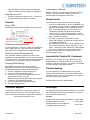
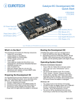
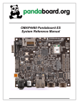
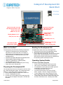
Catalyst LP Development Kit
Quick Start
CTLP1007
CTLP1008
DC Power Input (J29)
VGA Output (J61)
Ethernet (J63)
Audio in/out (J20, J23, J54)
PS/2 Keyboard, Mouse (J34)
Serial 1 and 3 (P1)
USB 0 to 3 (J3, J4)
CompactFlash (J71)
SATA1 (J67)
SD/MMC (J51)
Display Adapter in J11
PCIe (J12, J14, J15)
Mini PCIe (J16, J17)
Maintenance Port (P2)
Power LEDs
Status Display (D36)
Reset Switch (SW1)
On/Off Button (SW2)
What’s in the Box?
Booting the Development Kit
The development kit includes the following components:
• Catalyst LP Development Kit carrier board with
D510 dual-core (finned heat sink, CTLP1007) or
N450 single-core (x-shaped heat sink, CTLP1008)
• 10.4-inch SVGA TFT LCD with touch screen and
backlight inverter
®
• Windows Embedded Standard CompactFlash card.
• Catalyst Module Display Adapter board
• USB key, FreeDOS boot, for BIOS updates
• 12 VDC adapter and AC cord
• Black DB9FF cable (for maintenance port P2 only)
• Stylus and screen cleaning cloth
Complete these steps to boot your development kit:
1. Insert the boot card into the CompactFlash socket.
2. Momentarily press the On/Off button (SW2).
Power LEDs D25 and D26 light, and the Port 80 Status
Display (D36) indicates BIOS boot loader progress.
After several seconds, the Eurotech logo appears and
the operating system (OS) begins to boot.
Preparing the Development Kit
Your development kit has been designed to work out of the
box. When handling the system, use a wrist strap and/or
ESD mat. Follow these steps to prepare it for use:
1. Ensure display adapter is seated well in socket J11.
2. Connect a keyboard and mouse.
3. Connect the 12 VDC adapter to DC power input J29,
then connect the adapter to AC power. LED D27 will
illuminate.
110125-40011
Operating System Details
Windows Embedded Standard
•
•
•
•
•
•
Press CTRL+ALT+DELETE for the login screen.
User name is “Administrator” with no password.
To recalibrate the touch panel and enable right-click
functionality, run “hwincal.exe” from the
C:\ProgramFiles\Tsharc\ window.
You can find the version of your OS in Control
Panel→System→General→Support Information.
To enter Standby mode, select Stand by from the
Start→Shut Down menu. Press On/Off to resume.
To shut down, press On/Off or select Shut Down from
the Start→Shut Down menu. Wait till power LEDs
August-2010
D25 and D26 turn off before disconnecting power.
LED D27 turns off when the adapter is unplugged.
Wind River Linux 3.0
•
Release is expected in October 2010. Contact your
Eurotech sales representative for updates.
Features
Power LEDs
The following LEDs indicate the status of system power:
D27: Power is connected
D26: Standby power
D25: Normal operating power
Resetting the Development Kit
To reset, press SW1. Press only if there is a catastrophic
fault or hang of the OS. User data can be lost and the
boot media can be corrupted by an unexpected reset.
Shutting Down the Development Kit
If the shutdown methods provided by the OS are not
available, press and hold SW2 for about seven seconds to
turn off the system. The same cautions about potential file
corruption from a reset apply to this type of shutdown.
Changing BIOS Settings
BIOS defaults have been selected to enable the
development kit to operate in a standard configuration.
Complete these steps to change the BIOS settings:
1. Connect a keyboard to the development kit.
2. Power up or reset the development kit.
3. Press the F2 key a few times around the time the
system reaches POST code “80”.
Within a few seconds, the BIOS setup utility appears.
4. Change the applicable BIOS settings.
5. In the Exit tab, select Exit Saving Changes.
6. Reset the development kit.
Technical Support
The Eurotech support site includes errata reports, the
latest releases of documents, and developer’s forums.
These resources are available to registered developers at:
http://support.eurotech-inc.com
Connecting to a Network
Network settings are configured to operate with a DHCP
network. To connect to your network, connect your
network cable to the Ethernet socket (J63).
Known Issues
The following are known issues at the time of writing:
• Sockets J10 (SDVO/ADD-2) and J52 (SD/MMC1) are
not supported. They are only for Catalyst LPs built for
backward compatibility with the Catalyst Module XL.
• After a normal system power off, the system may
sometimes hang after On/Off has been pressed
(POST code 76). Press the reset button to restart.
• In some configurations the LCD backlight may be dim
after resuming from standby.
• PCIe bus 3 (J15) may not work with all cards.
• Slower IDE settings in the BIOS will not take effect at
the operating system level.
• As shipped, only SATA1 port (J67) is available for use.
For dual-SATA operation, select “SATA Only” in the
BIOS. “SATA Only” mode disables the CompactFlash
port, so be prepared to boot from another medium.
A full list of known issues and errata is posted on the
Eurotech support forums.
Important for Catalyst XL Customers
Note that if you currently have a product based on the
Catalyst Module or Catalyst Module XL, the Catalyst LP
processor module will not boot in your design. The DesignIn Guide describes compatibility options.
Troubleshooting
If you are directed to use Maintenance port P2 while
working with Eurotech staff, use the black DB9FF cable
supplied in this kit. P2 is not for application use and does
not follow the EIA-232C standard.
See the support forums for additional tips.
Next Steps
For additional information about the Catalyst LP, download
the following documents from the support site or contact
your local sales representative.
Document
Catalyst LP Development Kit User Manual 110125-4000
Catalyst LP Design-In Guide
Catalyst Module XL and Catalyst LP
Compatibility Application Note
110125-40011
110125-1000
110125-1001
August-2010