1
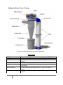
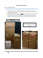
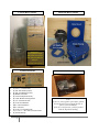
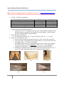
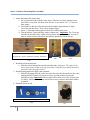
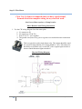
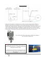
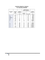
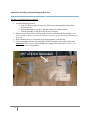
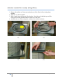
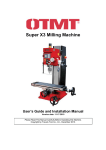
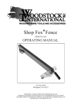
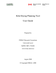
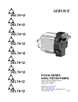
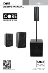
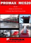
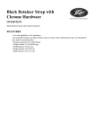
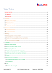
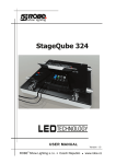
CV1800 and CVMAX Owner’s Manual Shown with 30 gallon collection drum (not included) and optional Clean Out Box. 145 Nix Road Liberty, SC 29657 1-888-299-0221 www.ClearVueCyclones.com Disclaimer WARNING: All persons by purchasing a motorized dust collection system, motor, or individual parts from CLEAR VUE CYCLONES, or using these instructions which are provided as suggestions only, agree to the following disclaimer: Installing and/or operating this motorized dust collection system, or use of individual parts, involves the risk of serious bodily injury or even death. The buyer and user accept total responsibility for any and all operation or use that may lead to personal injury, economic loss, social distress, other losses, costs and damages. Seller is not responsible for injuries and or damages of any kind resulting from operating this motorized dust collection system, motor, or use of individual parts or instructions. All Rights Reserved, June 2013 Duplication of any part of this manual without the expressed written permission from Bushey Enterprises, Inc. is prohibited. IMPORTANT! Minimum Recommended Ceiling Height A minimum floor-to-ceiling height of approximately 8 feet (96 inches) is required. The content of this manual is based upon the assembly of a CV1800 cyclone under an 8’ ceiling. If your ceiling is lower than this recommended height, please contact us to discuss your unique situation and possible options. Leaks In order to maximize performance of your dust collection system, it will be imperative to check for leaks. Leaks on the suction side of the system will reduce the CFM (cubic feet per minute) performance levels. We recommend the sealing of all connections in your ducting and on the intake side of the cyclone. Leaks in the collection bin or at the bottom of the cyclone are major problems. Such leaks will cause an up-flow of air through the cyclone and prevent the dust from entering into the collection bin. This will affect the separation efficiency of the cyclone and more dust will advance through to your filters, which may cause blockage. Leaks found anywhere after the dust reaches the blower may be blown back into your shop. This is a hazardous situation and these leaks should be sealed immediately. 2 CV1800 Owner’s Manual – © Clear Vue Cyclones 2013 Table of Contents Getting to Know Your Cyclone………………………………………………………... 5 Step 1: Check Box Contents…..………………………………………………………. 6 Step 2: Build and Mount Wall Bracket….…………………………………………….. 8 Step 3: Construct Motor/Impeller Assembly...………………………………………… 9 Step 4: Install Motor/Impeller Assembly……………………………………………… 11 Step 5: Assemble Transition…………………………………………………………… 13 Step 6: Attach Transition to Blower Housing…………………………………………. 14 Step 7: Attach Blower Housing to Cyclone…………………………………………… 16 Step 8: Install Intake Chute…………………………………………………………… 17 Step 9: Assemble Filter Assembly……………………………………………………. 18 Step 10: Install Cleanout Box.………………………………………………………… 19 Step 11: Attach Filter/Cleanout Assembly to Cyclone……………………………….. 20 Step 12: Modify and Install Trash Can………………………………………………... 21 Step 13: Wire Motor…………………………………………………………………... 22 Exhibit A: Maska Taperlock Installation Instructions………………………………... 25 Addendums: Installing Aluminum Hanging Brackets……………………………………… Assemble Filter Assembly (Flanged Filters)…………………………………. 27 28 3 CV1800 Owner’s Manual – © Clear Vue Cyclones 2013 There are certain items that are needed for successful installation of your Clear Vue Cyclone System. Below you will find a listing of those items: Tools 9/16 Wrench 7/16 Wrench 3/32 Hex Key Drill Bits Drill Level 6 Foot Ladder Tape Measure Box Cutter Items to Purchase (if you don’t already own) 30 Gallon Trashcan with Lid or other desired collection bin 1 tube DAP Alex Plus Clear Silicone Caulk ½” thick by 1” wide gasket ½ Sheet of ¾ Plywood 8 - #12 x 3” 1–2x4x8 These items are not necessary if you have 20 – 1 ½” screws purchased the Aluminum Mounting Brackets 8 - #12 x 2 ¼” (Single Phase Systems Only) Installation Time Installing your CV1800 cyclone takes approximately 4-6 hours to assemble with two people. Ducting your shop tends to be more time consuming and varies based on the size of the shop, design and labor. 4 CV1800 Owner’s Manual – © Clear Vue Cyclones 2013 Getting to Know Your Cyclone * *Items are not included and may be purchased separately. Specifications CV1800 CVMAX 5 HP Leeson Motor Wynn 9L300BL Filter Impeller Blower Housing Transition 5 Footprint: 24” x 53”, MAX air flow through 6” pipe 1442 CFM Footprint: 24” x 53”, MAX air flow through 8” pipe 1935 CFM 230 volts, 1 Phase, 20.8 FLA, 7/8” shaft, 50lbs, 1 year manufacturer’s warranty 12.75” x 34” (300 sq. ft.) Backward Inclined Material Handling Impeller complete with taper lock bushing ¾” MDF Board Top and Bottom with 1/8” clear PETG plastic wrapper MDF with clear PETG wrapper or single PETG wrapper for straight transition CV1800 Owner’s Manual – © Clear Vue Cyclones 2013 Assembly Instructions Step 1: Check Box Contents 1. Prepare the site where you will be installing your cyclone. If there are any space or placement issues, please contact our office so that we may help resolve them before you begin unpacking your boxes. 2. The cyclone components are shipped in three boxes. (Note: If you are present at the time of delivery and there is visible damage to the boxes, please note this with the carrier.) 3. Open the boxes, empty the contents and check for any hidden damage. If anything is damaged or missing, please contact our office as soon as possible by phone or email. Shipped Boxes (Please note: if you purchased filters with your Clear Vue Cyclone system, they will be shipped directly from the manufacturer.) Filter Boxes 6 CV1800 Owner’s Manual – © Clear Vue Cyclones 2013 Cyclone Box Contents Materials Box Contents Intake Chute & Clear Flex Hose Cyclone Body Please note: If you purchased blast gates with your system, they will be included in this box. (Blast Gates sold separately) Cyclone Hardware (4) 3/8 x 1 ¼” Motor Bolts (4) 3/8” Flat Washer (motor) (4) 3/8” Lock Washer (motor) (8) Rubber Grommets (4) ½ Pan Head (intake chute) (6) 1 5/8” Blower Housing Screws (4) 1 ¼” Transition Screws (8) ¼ x 20 Lock Washers (28) ¼ x 20 Flat Washers (24) ¼ x 20 Nuts (4) ¼ x 20 x 7” Threaded rods (4) ¼ x 20 x 1 ½ Hex bolts (transition bolts) (2) 6” Band Clamps 7 Motor Box Contents Leeson Motor Note: If there is a key taped to your motor, please do not discard. You will need this key as part of your installation. If the key is not present, it will be packed with the taperlock bushing. CV1800 Owner’s Manual – © Clear Vue Cyclones 2013 Step 2: Build and Mount Wall Bracket Note: Aluminum Hanging Brackets are available for purchase at www.ClearVueCyclones.com. Instructions for installing Aluminum Hanging Brackets at located at the end of this document. 1. Cut the “L” Bracket components: Instructions (2) vertical members from 2 x 4 lumber (2) horizontal members from 2 x 4 lumber (1) Bracket back from ¾” plywood (2) bracket sides from ¾” plywood CV1800 9 ½” long 18” long 12” x 26” 9 ½” x 19 ½” CVMAX 9 ½” long 20” long 12” x 26” 9 ½” x 21 ½” 2. Join the vertical and horizontal members: a. Using two #12 x 2 ½” or longer screws, join the vertical (shorter) members to the horizontal (longer) members by driving the screws through the vertical member into the end grain of the horizontal member. 3. Attach the sides to the bracket: a. Glue the bracket sides to the “L” bracket. Reinforce with 10 – 1 ½” screws. 4. Mount “L” brackets to the wall: a. The top of the bracket back should be at least 8’ (96”) or more above the floor. b. If you are using a collection bin that is higher than 28”, you will need to increase the height of your “L” brackets accordingly. c. Attach the bracket back to the wall by driving at least 8 or more screws through the bracket into the wall studs. Important: These screws will be holding the weight of the entire unit, so #12 x 3” or longer screws are recommended. d. Attach the assembled bracket sides to the mounted bracket back using #12 x 2 ¼” screws. The tops and outside edges of the components should align. (1) (2) (4) 8 (3) (4) CV1800 Owner’s Manual – © Clear Vue Cyclones 2013 Step 3: Construct Motor/Impeller Assembly 1. Attach threaded rod to motor plate: a. Set up 4 threaded rods with the items shown. The box in yellow indicates items that will be set up later. Set these aside for now. Leave about 2 to 2 ½” between item groups. b. The washer on the top of the shock mount should be approximately 4” high. Leave the jam nuts loose. They will be tightened later. c. Insert ¼” threaded rod through each hole of the MDF motor plate. d. Thread rod into T-nuts until they almost “bottom out”. Important: The T-nuts are installed on the rabbet side, which is facing down in the picture. Make sure the Tnuts are on the bottom side before inserting the threaded rod from the top. Group 1 Order - Flat Washer, Lock Washer, and Nut Group 2 Order – Nut, Nut, Flat Washer, Grommet, Flat Washer (1b) (1c) (1a) 2. Install the motor mount plate. a. Slide the motor mount plate onto the threaded rods. Important: The strips on the motor mount plate should be facing toward the ceiling during assembly and when mounted on the hanging brackets. 3. Install the hanging bracket upper shock mounts: a. Slide the grouping from the yellow box onto the top of the threaded rod, above the hanging bracket. Tighten the jam nuts so they are snug without causing the bushings to bulge. Important: The top nuts will be used to level the cyclone after it is hung. Afterward, the bottom nuts will be used to compress the bottom rubber grommets. 4. Stand the motor on end. Group 3 Order - Flat Washer, Grommet, Flat Washer, Nut, Nut (3a) 9 (4) CV1800 Owner’s Manual – © Clear Vue Cyclones 2013 5. Attach the motor to the mounting assembly: a. Turn the mounting assembly over and set it on the motor, with the bracket holes and motor mounting holes aligned. b. Install 4 motor bolts (1/2 – 13) into the holes using a washer and lock washer on each bolt. 6. Tighten each motor bolt securely. Completed Motor/Impeller Assembly NEVER run the Impeller on the Motor, or the Motor by itself until the system is completely assembled! Doing so may cause physical damage to your system, breakers to POP, or harm to yourself. 10 CV1800 Owner’s Manual – © Clear Vue Cyclones 2013 Step 4: Install Motor/Impeller Assembly WARNING: Improper installation of your impeller can lead to the impeller coming off during use. Significant damage to your system and/or bodily harm can result. It is imperative that you read and follow these directions closely. Detailed assembly videos can be found under the Education Center/Assembly Instruction section of our website at www.clearvuecyclones.com 1. Position the impeller: a. Remove the MDF shipping protector and discard. It is unnecessary for installation. b. You will find the taperlock and screws in a small box inside of the materials box. The motor key will either be included in this box or taped to the motor with blue tape. Do not discard the key – you will need this as part of your installation. c. Slip on impeller onto the motor shaft. d. Place the taperlock on the shaft of the motor, lining up the key holes of the shaft to the taperlock. (1d) (1e) (1e) e. Insert the key and lightly tighten the setscrew against the key using a 3/32” to 7/64” allen wrench until it cannot fall out. f. Insert the 3 bolts, included with the taperlock, through the large, non-threaded holes on the taperlock. Thread them into the three threaded holes on the impeller. 2. Tighten taperlock bolts: a. Lift the impeller so that the taperlock is flush with the tip of the shaft. Tighten the bolts one at a time, around in a circle, until they are all tight: i. Snug one bolt down, then a second, then a third. As you tighten, the impeller is drawn up towards the motor. ii. When you return to the first bolt, it will be loose. This is due to the other bolts having pulled the taperlock closer to the hub. iii. Repeat this process until the bolts are all torqued to the specifications outlined in the Maska’s Installation Instruction sheet. (Exhibit A, pg. 25) Upon completion, there should be a minimum of ¼” clearance between the impeller and mounting plate bolt-head. (Note: We are using a JA 11 CV1800 Owner’s Manual – © Clear Vue Cyclones 2013 bushing with a reverse mount. The torque requirement is 5 ft/lbs.) 3. Tighten the setscrew against the key using a 3/32” to 7/64” allen wrench. 4. Hang motor-impeller assembly: a. With the help of your installation partner, slide the assembly onto the wall bracket. The clear span in the front will have the additional MDF rail for added strength. b. Secure the motor-impeller assembly to the wall assembly before operation of the cyclone. This is best done after finishing cyclone assembly. If needed, move the motor-impeller assembly in or out a couple of inches to make installation of the cyclone easier. c. Securing the assembly as well as height adjustments will be completed later. 12 (1f) (2i) (2iii) (4) CV1800 Owner’s Manual – © Clear Vue Cyclones 2013 Step 5: Assemble Transition 1. 2. 3. 4. 5. Begin by inserting the plastic parts in the grooves to form the transition chute. Slip the transition chute into the slot of the transition bottom. Drill 4 small pilot holes in the transition bottom. Attach the transition chute to the transition bottom using four transition screws. Apply clear silicone caulk to the exterior seams of the plastic and transition sides. The caulk will go on white and dries clear. It can be easily cleaned up with water. (1) (2) (4) 13 (3) (Completed Transition) CV1800 Owner’s Manual – © Clear Vue Cyclones 2013 Step 6: Attach Transition to Blower Housing Important: Do not remove the white piece of wood located in your blower housing. This wood counters the sound as the blade passes by the larger opening of the blower housing. The following are assembly instructions for the 90° transition: Using a 7/16” wrench, loosen the front 4 bolts on the blower housing and open it slightly. Slip the transition into the blower assembly. Tighten the bolts on the blower housing to clamp the transition in place. When the transition is positioned, drill through the (4) holes in the MDF sides using an appropriately sized bit. 5. Insert a bolt and washer in each dedicated hole from the inside with the ends going to the exterior of the assembly. 6. Secure the transition using a washer, lock, washer and nut on each bolt. 7. Seal the transition to the blower using clear silicone caulk, being sure to cover all seams. Important: Sealing the transition is very important. If there are any leaks, the unit will blow fine dust into your shop. 1. 2. 3. 4. (1) (5) 14 (4) (6) CV1800 Owner’s Manual – © Clear Vue Cyclones 2013 The following are assembly instructions for the straight transition: 1. Using a 7/16” wrench, loosen the front 4 bolts on the blower housing and open it slightly. 2. Place the dedicated pieces of wood on the blower housing and tighten the bolts on the blower housing. 3. Place the straight transition over the opening of the blower housing and line up the holes. 4. Insert a washer and bolt from the inside with the end of the bolt going outside the blower housing. 5. Secure the bolt from the exterior with a washer, lock washer and nut. 6. Seal the seams with clear silicone caulk. (1) (2) (2) (3) (4) 15 (5) CV1800 Owner’s Manual – © Clear Vue Cyclones 2013 Step 7: Attach Blower Housing to Cyclone 1. Before you begin, it is important to caulk the seams of your blower housing. 2. Determine the desired orientation of the blower housing and cyclone inlet chute. Note: the blower discharge can be rotated and positioned in any direction to suit the needs of your shop. 3. Place the cyclone in a drum or bin in order to keep the unit from tipping over as the blower housing is attached. If a drum or bin is not available, you will need another person to assist you in the attachment. 4. Option: the next section of the installation manual will discuss attaching the intake chute. This may be installed now or after the blower housing is attached to the cyclone. In this installation manual, we will be installing the intake chute after the blower housing is attached to the cyclone. 5. Attach the blower housing to the top of the cyclone using 6 – 1 5/8” screws. Be sure not to over tighten as the plastic will crack. 6. In this next step, remove the cyclone and place a piece of plywood on the top of the trash can. Lift the cyclone/blower housing into place around the impeller. 7. Slip a board or series of boards under the cyclone to lift the unit until the blower house is close to the motor plate. 8. Install the (6) clips on the blower housing. Leave the clips loose enough to allow for rotation of the cyclone if the intake chute needs to be installed. If the intake chute has been installed, then position the cyclone and lock the (6) clips down. Note: the motor plate may not sit flush to the blower housing. This is normal. 9. Use a level to ensure that the cyclone is level. Adjust the nuts up to the bushings on the motor mounting rods, if necessary. 10. Once the system is mounted, secure the motor mount assembly to the “L” brackets using either 1 ¼” sheet rock screws or ¼ - 20 x 1 ¼” bolts. Pre-drill holes using drill bits so the assembly does not crack. (8) (6 & 7) 16 (8) CV1800 Owner’s Manual – © Clear Vue Cyclones 2013 Step 8: Install Intake Chute 1. 2. 3. 4. Rotate the cyclone, if necessary, so the chute is accessible. Attach the chute to the cyclone using 4 - #6 x 3/8” long screws provided. Seal the intake chute with clear silicone caulk. Rotate the cyclone, if necessary, into position and tighten the (6) clips on the top of the blower housing. (2) (2) You may notice a small black grommet near the intake chute. This serves to prevent dust from collecting in the dead space of your cyclone. If you did not purchase filters with your CV1800 or CVMAX system, please skip to Step #12. 17 CV1800 Owner’s Manual – © Clear Vue Cyclones 2013 Step 9: Assemble Filter Assembly - (Flangeless Filters) 1. 2. 3. 4. 5. 6. Stack the two filters together. Run a bead of silicone caulk around the outside joint where the two filters meet. Place a washer on the ¼ - 20 x 1” hex bolt. Wrap the band clamp around the joint. Insert the bolt through the hole on the band clamp and tighten. Place another ¼ - 20 x 1” washer, a ¼” lock washer and a ¼ - 20 wing nut on the hex bolt and tighten. (3) (5) (1) (6) 18 Finished product CV1800 Owner’s Manual – © Clear Vue Cyclones 2013 Step 10: Install Clean Out Box If you did not purchase our clean out box, you may build your own. The only requirement is that the box be airtight when closed and have an opening to remove residual dust from filters. To build your clean out box: 1. Determine the height of your clean out box. a. Place the filter assembly under the transition. b. Measure the distance from the top of the filters to the bottom of the transition. The distance will be the overall height of the clean out box. 2. Box suggestions and recommendations: a. The box can be made from plywood or MDF. b. It should be 14” x 14” x (height measured in step #1) c. Leave an access opening in the front of the box and build a gasketed cover plate. (1b) (Example of box) (Example of cover plate) To install your clean out box: 1. Place the filter stack on top of the box. 2. Attach the clean out box to the bottom of the filter assembly using a bead of clear silicone caulk where the filter meets the clean out box. The silicone caulk will hold the filters securely in place and can be removed easily by cutting the bead with a razor knife. 3. If you purchased a clean out box from our web page, caulk the seams of the clean out box. 4. Note: If you are installing your system higher than 96”, you will need to support the Clean Out Box from below. Example of the clean out box available for purchase at www.clearvuecyclones.com 19 CV1800 Owner’s Manual – © Clear Vue Cyclones 2013 Step 11: Filter/Cleanout Assembly to Cyclone 1. Slide the filter-cleanout assembly under the transition. The fit should be exact. 2. Attach the filter-cleanout assembly to the transition: a. Screws: Drill pilot holes in the MDF. Attach the filter-cleanout unit using 1 ¼” #6 sheet metal screws. b. Duct Tape: Use high quality HVAC silver duct tape around the seam between the filter and the transition. 3. Caulk where the transition meets the filter assembly (unless you used the tape). Example 20 CV1800 Owner’s Manual – © Clear Vue Cyclones 2013 Step 12: Modify and Install Trash Can These instructions show the modification and installation of a 30 gallon corrugated metal trash can. A different type of container may be used; however, it must be air tight upon completion. 1. Modify the lid: a. Cut a hole in the center of the lid about ½” smaller than the 6” flex house supplied with the cyclone. The easiest way to do this is to draw a 3” radius (6” diameter) circle, centered on the top using a fine point marker. Draw a 2 ¾” radius (5 ½” diameter) circle inside of it. Cut on the inside line using snips, jig saw or other appropriate tool. b. Using pliers, bend a ¼” lip up all the way around until you are able to screw the hose into the lid. c. Caulk the hose from both sides of the lid to seal it in place. d. Install a rubber weather strip (approx.. ½” thick x 1” wide) to the underside of the lip where it contacts the trash can. This will provide a seal. e. Option: For further reinforcement, bungee cords may be stretched across the lid, on either side of the flex hose, and attached to the ends of the handles. 2. Attach the lid to the cyclone: a. Place the 6” flex hose clamp over the top of the flex hose. Make sure it is loose. b. Install the lid by placing the 6” flex hose over the base of the cyclone. c. Tighten 6” flex hose clamp to secure flex hose to the base of the cyclone. To ensure an airtight seal, caulk around the top of the flex hose. (1a & 1b) 21 (1c) (1d) CV1800 Owner’s Manual – © Clear Vue Cyclones 2013 Step 13: Wire Motor Clear Vue Cyclones recommends that you have a professional, licensed electrician complete wiring on any electrical work. Our Leeson Motor requires a 30 amp breaker. Motor Rotation and Wiring Instructions 1. Use the CW wiring diagram from the motor plate. a. L1 connects to P1 b. L2 connects to (T4 & T8) c. P3 & T1 & T5 – wire together d. The ground wire (bare wire) goes to a green screw inside the motor connection box. This is a typical two-pole single throw relay. The contact should be rated for at least 30 amps and the coil voltage should be 110V. This allows for the ability to switch the coil “on and off” with a regular light switch or a remote control that turns lights on and off. Physical Wiring Diagram 22 CV1800 Owner’s Manual – © Clear Vue Cyclones 2013 Electrical Diagram Please note, the ground wire should never be used as a current carrying conductor. Rather, it should be connected to the motor body, as well as other metal parts of the motor, in order to dissipate stray electrical currents. The proper way to wire this using a 110-volt relay coil is to run a four-conductor cable from the electrical panel. L1 (black) and L2 (red) are hot legs, Ground (bare or green) and Neutral (white). The Neutral conductor will allow you to run a 110 volt relay or other device if connected between the neutral and one of the hot legs as shown above. (Pre-wired Electrical Box (with remote) available for purchase at www.ClearVueCyclones.com) Note: Once the motor is wired, the motor shaft and impeller blade should be turning counter-clockwise when viewing from below. (ie: looking up at the motor and impeller from the floor) A rotation sticker on the blower housing points in the direction the curved part of the impeller blades should be spinning. 23 CV1800 Owner’s Manual – © Clear Vue Cyclones 2013 Option: The diagram below uses a 220 to 24 volt step down transformer to power a relay with a 24-volt coil. This gives the ability to use the existing wiring with the advantage of running low voltage wiring and switches around your shop. 24 CV1800 Owner’s Manual – © Clear Vue Cyclones 2013 Exhibit A: Maska Taperlock Installation Instructions 25 CV1800 Owner’s Manual – © Clear Vue Cyclones 2013 26 CV1800 Owner’s Manual – © Clear Vue Cyclones 2013 Addendum: Installing Aluminum Hanging Brackets Installing Aluminum Hanging Brackets 1. Assemble hanging brackets a. Take (1) short leg and (1) long leg of the bracket and assemble using a bolt, washer and nut. b. Mount supporting leg to the L-bracket using bolt, washer and nut. c. Follow procedure A and B for the second L-bracket. 2. Measure where the brackets will be mounted on the wall and mark accordingly. Note: some customers choose to mount the brackets to a piece of plywood before mounting to the studs. 3. Drill mounting holes in L-brackets using an appropriate sized drill bit. 4. Using mounting hardware (not included), mount L-brackets to the studs of the wall. Important: These screws will be holding the weight of the entire unit, so #12 x 3” or longer screws are recommended. 27 CV1800 Owner’s Manual – © Clear Vue Cyclones 2013 Addendum: Assemble Filter Assembly - (Flanged Filters) 1. Remove the rubber seal from one (and only one) of the filters before joining them together. 2. Stack the two filters together. 3. Drill (2) pilot holes through the filter brackets. Size holes to fit the bolts you will be using. Holes can be positioned in the corners or on the sides. 4. Assemble the two filters using bolts, washers, lock washers and nuts. 28 (1) (1) (3) (4) CV1800 Owner’s Manual – © Clear Vue Cyclones 2013