1
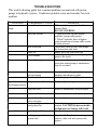
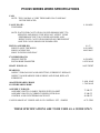
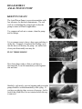
SERVICE
DELTA^Q
DELTA^Q
DELTA^Q
DELTA^Q
DELTA^Q
DELTA^Q
DELTA^Q
P10V45 SERIES
AXIAL PISTON PUMPS
DELTA^Q
DELTA^Q
Plant Location and Mailing Address
10827 Tower Oaks Blvd
Houston, TX 77070
Website: www.deltaq.com
Email: [email protected]
Phone: (281) 807-1840 or (800) 650-3110
Fax: (281) 807-4457
12-2008
INTRODUCTION
This service manual contains procedures for trouble shooting and repairing the
DELTA^Q LTD. P10V45 series piston pump. It does not include the controls, see Control
Service Manual for that information.
It is DELTA^Q LTD. policy to continually upgrade their products. This may from time
to time make some of the discussion in the repair manual not agree exactly with the components you are looking at, if a major change had taken place that would be reflected in
the Model Number.
WARNING! Before breaking a circuit connection, make certain that power is off and system
pressure has been released. Lower all cylinders, discharge all accumulators and block
any load that might move and generate pressure.
PUMP DESCRIPTION: The P10V45 series piston pump is open loop and axial in
design. Split flange and SAE O-Ring Ports are available on either side or rear. An SAE
“A & B” Mounting pad is available on the rear to drive a small pump. The “P10V45” pump
may be driven by any source of power; Diesel, Gasoline, Electric. Plumbing is of the utmost
importance to prevent cavitation at the inlet as well as compliance on the outlet. In some
applications super-charging the inlet may be required. The pump is rated for 4000 psi
therefore the discharge piping must be capable of that pressure. There are a variety of controls
available such as pressure compensation, load sense, torque limiter and variations of
these. Controls are continually being developed so check with DELTA^Q if a particular control is required.
RELATED PUBLICATIONS:
Installation dimensions for the “P10V45” series piston pump and controls are not included in
this manual. Individual parts numbers are also not included. Refer to the related publications
that include this type of information.
Sales and Application (includes installation drawings).
Theory of Pump operation
Theory of Control operation
Service Book, pump (this booklet)
Service Parts Book, pump
Approved Fluids
TROUBLE SHOOTING
This trouble shooting guide lists common problems encountered with piston
pumps in hydraulic systems. It indicates probable cause and remedies for each
problem.
TROUBLE
Excessive noise in
pump.
PROBABLE CAUSE
Low oil level in reservoir
Air in the system
Inlet restriction
Thick oil
Cold Weather
Pump overheating
Internal leakage
Heat exchanger
not functioning
Fluid level low
REMEDY
Fill reservoir to proper level with recommended fluid.
DO NOT OVERFILL
1. Open reservoir cap and operate
hydraulic system until purged.
2. “Bleed” hydraulic lines at highest
point downstream of pump while system
is under pressure.
Check inlet (suction) lines and fittings
for obstructions and leaks
Empty and refill with correct oil
Actuate hydraulic system until pump is
warm to the touch.
If determined that excessive case flow
exists then return pump to maintenance
shop for overhaul
Locate trouble and repair, refer to
machine manufacturers guide
Add oil to proper level, determine cause
System not
Compensator malfunctioning Replace adjust or repair
developing pressure
Loss of fluid
High case flow
Return to maintenance shop for repair
Broken shaft
Return to maintenance shop for repair
System shut off
valves not open
Pump rotating in
wrong direction
Locate and open
Failed hydraulic line
Leaking pump seals or
system seals
Correct by changing pump or drive
rotation. CAUTION do not run in this
configuration or damage will result!
Locate and repair
Check the O-Ring between mating pump
surfaces, shaft seal and system seals,
replace.
P10V45 SERIES WORK SPECIFICATIONS
CAM:
NOTE: THE CAM HAS A VERY THIN HARD COAT AND MAY
NOT BE REFACED.
VALVE PLATE:
THICKNESS
0.190 MIN
NOTE: WATCH FOR CAVITATION CAUSED EROSION NEXT TO
KIDNEYS AND HOLES THIS WILL NOT AFFECT PUMP
PERFORMANCE BUT MAY INCREASE NOISE AND
REDUCE LIFE. CAVITATION SHOULD NOT BE PRESENT
AND THE CAUSE SHOULD BE ELIMINATED.
PISTON ASSEMBLIES:
SHOE FLANGE THICKNESS
SHOE FACE RECESS
SHOE TO PISTON END PLAY
0.147
0.010 MIN
0.005 MAX
CYLINDER BLOCK:
GROOVE DEPTH
PISTON BORE DIAMETER
0.020 MIN
0.6705 MAX
SHAFT END PLAY:
0.002 TIGHT
BEARINGS:
INSPECT FOR GALLING AND OR PITTING, IF PRESENT REPLACE.
INSPECT CAM BEARINGS FOR SCORING AND WEAR, REPLACE
IF PRESENT.
ADAPTER BEARING BORE
COVER BEARING BORE
ASSEMBLY TORQUE:
ASSEMBLY BOLTS (4) EARLY DESIGN WITH GASKET
ASSEMBLY BOLTS (4) CURRENT DESIGN WITH SEAL
CONTROL AND COUNTERBALANCE POST
CASE LEAKAGE AT 2500PSI AND 110°F CONTROL SET >3000PSI
2.4404 MAX
1.7805 MAX
75 LB-FT
55 LB-FT
40 LB-FT
<0.75 GPM
THESE SPECIFICATIONS ARE TO BE USED AS A GUIDE ONLY
DISASSEMBLY
AXIAL PISTON PUMP
KEEP IT CLEAN!
The Axial Piston Pump is a precision machine with
low tolerance for dirt and contaminants. The real
work in overhauling the pump begins before the
pump is removed from its application.
Use commercial solvent or steam, clean the pump
and its fittings.
45.0001
It is a common error to leave a hose open and drop it
in the dirt. Granuals of sand and dirt finding a way
into the hose will destroy the pump - no matter how
clean your disassembly area may be.
PLUG THOSE HOSES!
45.0002
Have hose plugs ready so that as each hose is
disconnected, it can be immediately sealed against
dirt and dust.
45.0003
Similarly, each newly exposed opening and port in the
pump should be sealed immediately with a plug. If
you have no plastic plugs, use new clean rags - but be
careful that cloth fibers are not retained when the rag
is removed.
45.0004
Naturally the work area must be clean and well lighted. Do not work on hydraulic pumps in areas near
welding operation. The welding “smog” you can see
in the air contains abrasives.
45.0005
Do not disassemble a pump outdoors or in other areas
open to wind or rapidly moving air which can carry
dust or dirt.
45.0006
It is not a good idea to smoke while overhauling the
pump - the ash in smoke is abrasive.
45.0007
Some controls have a “Load Sense Pin” be careful
not to lose the small piston when the hose is disconnected. This piston has no retainer and is free to fall
out on the ground.
DO NOT LOSE THIS PISTON!
45.0008
It will be useful to have some small plastic bags
handy so that small parts can be stored out of harms
way. Also a large plastic (Garbage) bag is ideal for
covering the pump overnight if you cannot complete
the overhaul in one day.
45.0009
Because the pump is disassembled shaft down, either
bore a 1 1/2 inch hole in the work bench or prepare a
wooden support block. A support block can be a
2X4X8 inches long. It should have a 1 1/2 inch hole
for the shaft, holes for the pump flange and some
method of securing the block to the bench top such
as a large vise.
45.0010
TOOLS NEEDED TO OVERHAUL THE PUMP
Torque Wrench capable of 55 LB-FT.
Allen Wrench 1/2“ for pump assembly bolts.
Allen Wrench 3/16” for control bolts.
Snap Ring Pliers Internal for Seal and Cylinder Block.
Soft Faced Hammer for driving the seal.
500 Grit Paper to re-face the Pistons and Cylinder Block and a lapping plate.
Tray of Mineral Spirits Solvent.
Seal Driver and Thimble to install the Seal.
Method to compress the Cylinder Block Spring.
Small fixture with three holes to assist installation of Loading Pins.
Needle Nose Pliers to install Loading Pins.
Arbor Press to install/un-install Shaft Bearings.
Round Tube to press bearings so not to damage the cage.
45.0011
Using the wood block previously made, secure the
pump to it and then mount the wood block in a large
bench vise.
Before starting to disassemble mark the relation
between the cover and Adapter. This will assure the
pump will go back together correctly.
45.0012
Remove the control and note the position of the orifice(s) if present. Note also that the adjustment
points to the inlet side.
45.0013
Loosen the four assembly bolts and remove the Cover. With the cover will come the Control Post and
C'Balance Post, these post will not have to be
removed further unless they are damaged.
Note the location of the Control and C'Balance Post
relation to the Adapter.
45.0014
Now remove the loose pieces, Valve Plate, Bearing
Cone, Bearing Shim, Dowel Pin, Control Piston,
C'Balance Piston with Spring and Molded O-Ring.
Inspect the bearing for pitting, the pistons for scoring and the valve plate for cavitation and scoring.
Replace any of the components that show these
signs of damage.
45.0015
Remove the Cylinder Block Assembly.
If the Cylinder Block is going to be reused it should
be disassembled to clean the spring chamber. The
spring chamber is a low pressure area and collects
contamination.
45.0016
See the section at the end of the pump disassembly
for “Cylinder Block disassembly”.
Remove the nine Pistons, Return Plate and Pivot
Ring as one unit.
Inspect the components for scratches, scoring and
wear, replace if needed. Inspect the bronze shoes
for wear and rounding, they can be reconditioned.
See the Work Specification page at the beginning of
this book.
45.0017
Remove the Cam and Shaft(with bearing cone) by
grasping the end of the shaft and lift straight out.
Note the end of the Cam with two holes position
relative to the Adapter, mark the Adapter so it will
go back in the same position.
Inspect the Cam face and journals for wear and scoring. The Cam face and journals have a thin hard surface and cannot be reconditioned, replace if worn or
scored.
45.0018
Inspect the bearing for pitting and replace if found.
Inspect the shaft for wear where the seal runs,
replace shaft if it is grooved.
Inspect the face of the pivot shoes and re face if
needed.
Remove the two Cam Bearing Halves, noting how
the anti-rotation tabs fit.
Inspect the surface of the bearings for scoring, they
can be refaced with 500 grit paper.
45.0019
Turn the Adapter upside down, with a suitable tool,
remove the seal Retaining Ring.
45.0050
Using a round bar (1 1/2 inch diameter) and a Rubber Hammer drive the Seal inward until it is free.
45.0021
IF THE CONTROL OR C'BALANCE POST IS DAMAGED
IT MUST BE REPLACED
They are both held in place with Loc-Tite 242 on
the threads, apply considerable CCW torque to
remove.
Note, the position of each relative to the Port Cover
and note there are no O-Rings.
45.0022
THE CYLINDER BLOCK SHOULD ALWAYS BE DISASSEMBLED AND CLEANED
A tool like this can be made from a 1/2 x 3 inch bolt,
two nuts and a washer (OD=1.21) with a flat ground
on the washer to clear the retaining ring ears to compress the spring. Or you can make one as shown as
TL008 in the tool section of this book.
45.0023
CYLINDER BLOCK DISASSEMBLY:
CAUTION! spring is under compression use care
when removing.
With a tool to compress the spring, snap ring pliers
(with the nose bent 90°) and an arbor press, compress
the spring just enough to remove the retaining ring, do
not over compress the spring.
45.0024
Pump Assembly
Keep it clean
Gather all the parts be sure they are clean. Coat all
rubbing parts such as Pistons, Cylinder Block,
Spools, Cam, and Valve Plate with 10W oil.
45.0025
45.0026
Set up the adapter on a suitable base. Be sure to note
the location of the case drain ports
Install the two 1/4“ roll pins(if they were removed) in
the top of the adapter. They can be driven in with a
hammer.
CASE DRAIN
CASE DRAIN
Press in the shaft bearing cup using a suitable tool
that allows bearing cup to seat against adapter bore.
45.0027
Press the shaft bearing cone onto the shaft with a suitable tool. Pay attention to the roller cage so it is not
crushed during assembly. The diameter of the pushing tool needs to be smaller than the inside diameter
of the cage.
See TL005/TL006 and TL004 in the tool section of
this book.
45.0028
If any of these components have been replaced the
bearing pre-load must be checked:
SHAFT
PORT COVER
ADAPTER
SHAFT BEARINGS
Required pre-load is 0.002/0.003 Inch. Using a base
shim of 0.080 and a dial indicater load the shaft up
and down while rotating, read the maximum movement. Add that amount to the 0.080 shim plus
required preload and grind a new shim to obtain.
Note required shim thickness for later use.
45.0029
Install the Cam Bearings making sure the anti rotation
tabs are positioned correctly in the recess.
Install the shaft with bearing cone.
45.0030
Install the cam assembly paying attention to which
end has the two holes (this is the Counter Balance
end). The orientation of the cam should have been
noted at disassembly.
45.0031
Lubricate the two journals with petroleum grease
before installing.
WITH CASE DRAIN HERE
Make a tool to hold the three loading pins as shown
here. Slide this fixture into the spline from the neck
end of the cylinder block not the inside.
This is not the only way to install the pins, use what
ever method works.
TL009
45.0032
Install the three loading pins with a needle nose plier
as shown, rotate each pin so the lip on the pin is outward.
45.0033
Now install the washer (there is only one) onto the
loading pins. Be sure the Washer OD fits inside
the three tabs on the Loading Pins.
45.0034
Place the spring on top of the washer just installed.
Using a tool that will allow you to compress the
spring (can be made from a bolt two nuts and a
washer). Compress the spring just far enough to
install the retaining ring, depressing it more will over
stress the spring.
45.0024
Assemble the rotating group as shown. Lubricate the
pieces with 10W oil before assembling.
45.0036
Using a device such as an O-Ring, wrap it around the
pistons, this will hold the assembly together while it is
installed into the adapter.
45.0037
Turn the rotating group upside down and lower it into
the adapter, rotate it slightly to align the splines in the
shaft with the splines in the cylinder block and pivot
ring.
45.0038
Now that the rotating group is assembled install the
Molded O-Ring to the top of the adapter, lubricate
the O-Ring first to hold it in place. Install the Bearing Shim and Cone onto the Shaft.
Install the C'balance Post and Control Post. Note the
position of each, the Control Post must be in the hole
next to the Control.
Apply Loc-Tite 242 (Blue) to the threads before
installing, torque to 40 LB-FT.
45.0039
C'BALANCE POST
45.0040
CONTROL POST
Note: these post do not require O-Rings.
Press the bearing cup into the port cover.
45.0041
Install the dowel pin next to the Control Post.
45.0042
Lubricate the underside of the Valve Plate with
petroleum jelly, this will keep it in place while the
cover is assembled. Assemble the Valve Plate to the
Cover being sure it sits flat on the Cover.
45.0043
Install the Spring onto the C'Balance Piston, lubricate the C'Balance Piston and Control Piston with
10W oil or Petroleum Jelly and install in/on their
posts.
45.0044
Note: If there was a stroke spacer it should be
installed under the Control Piston here.
Grasping the Cover assembly using your fingers to
hold the C'Balance and Control Pistons in place
install it onto the Adapter assembly noting the position of the C'Balance Post. The C'Balance Piston
with the Spring should reside on the same side of the
cam that has the two external holes discussed
earlier.
45.0045
Install the four 7/16 bolts with lockwashers.
Torque the bolts evenly to 55LB-FT.
45.0046
Turn the assembly onto it's cover.
Lubricate the seal inside and out with petroleum
jelly.
Using a seal thimble, install the seal. The seal can be
installed without a thimble but the shaft would need
to be buffed at the leading chamfer with 600 grit
paper before the shaft was assembled if not the seal
could be cut at assembly.
45.0047
45.0048
Install with open end of Seal towards pump.
Drive the seal in place with a seal driver, do not drive
too hard there is no stop and the seal will be driven in
to far.
45.0049
Install the seal retaining ring.
45.0050
Prepare to install the control, shown are two configurations, there are many. Note the positions of any external orifices and return them to their original locations.
Not all controls have orifices.
45.0051
The control adjustments should point to the inlet side
of the pump.
Install the four 1/4“ bolts, not all will have
lockwashers. Torque to 10 FT-LBS.
45.0052
The pump is now ready to re-install.
45.0053
Application Notes, Piston Pumps
Filtration
Inlet
• Use 100 mesh screen.
• Inlet filters are not recommended except for super
charged systems.
Outlet
• Filters, either pressure-line or return, should be
capable of keeping fluid cleanliness as follows:
Operating Pressure
ISO Cleanliness
<2000 PSI
18/16/14
2000 to 3000 PSI
17/15/13
>3000 PSI
16/14/12
Inlet Conditions
• Check pumps drive speed against required inlet
pressure.
• Make adjustments for altitude if necessary.
• Install pump below reservoir to assure flooded inlet
when possible.
• If necessary install charge pump on auxiliary pad
(SAE 'A' or 'B').
• Conditions must be met at lowest operating
temperatures.
Case Pressure “IMPORTANT”
• Use one case drain per pump, ½ inch dia. Minimum.
• Do not use filters or coolers in case drain lines.
• Case pressure must not exceed 7 PSI above inlet
pressure (Example: If inlet pressure is 10 PSI, case
pressure must not exceed 17 PSI).
• 25 PSI maximum case pressure.
• Use upper most case drain port.
• Connect case drain below fluid level in side of
reservoir.
• Run case lines in such a manner to prevent draining,
siphoning or air locking of fluid.
Compensator setting
• Compensator settings are factory set but may be field
adjusted.
• If adjustments are necessary CW rotation will
increase setting; CCW rotation will decrease setting.
Load Sense Lines
• Use of ¼“ O.D. steel or steel-braid load-sense lines
may be required for stability if distance from pump to
control valve is excessive.
• On load-sense controls, sense line must be
connected to pressure for high-pressure cut-off to
occur. For low-pressure standby the sense line must
be vented to tank unless dynamic load-sense pin is
used then line may be blocked.
Start-Up
• Install required gages prior to filling pump with fluid to
observe case pressure, system pressure and inlet
pressure to make sure it is within DELTA^Q ratings.
• Check all fittings to be sure they are tight.
• Fill reservoir with filtered approved oil.
• Fill pump case with filtered system oil. Make sure
case is at least half full before start-up. Internal leak
age will not provide enough lubrication if case is dry.
Pump must not run dry.
• Open any shut off valves between reservoir and
pump.
• If the pump is used in a closed outlet system, discon
nect the outlet line until pump is primed and pumping
fluid. Pump must not be allowed to pump into a
closed system application until the pump has
primed or damage to the pump will occur.
• Start prime mover and operate at minimum speed
and minimum pressure until all air is purged from the
pump. Stop the prime mover and reconnect pump
outlet hose then purge air from the system by starting
the prime mover and operating control valve.
• Check fluid lines for leaks. Inlet line must be
“air tight”.
• Re-check reservoir fluid level, add if necessary.
• Cycle pump observe system pressure, case pressure
and inlet pressure to ensure that they fall within the
pump rating.
Pump Rotation
• Can be changed by installing opposite rotation cover
and valve plate.
Application Assistance
• Professional application and controls engineering
assistance is available.
• Complete the pump application form and contact
DELTA^Q.
! WARNING
• Failure to comply with any of these
requirements and procedures will
result in a voided warranty