1
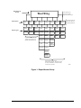
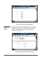
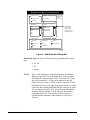
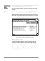
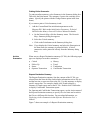
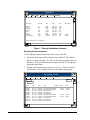
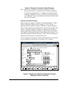
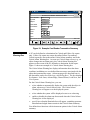
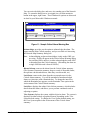
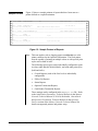
Metasys Network Technical Manual 636 Feature Software Section Technical Bulletin Issue Date 0696 Report Router / Alarm Management lntroduction ● Page Theory of Operation Setup Procedures 3 *3 10 ● Design Considerations 11 ● Report/Access Group Definition Procedure 12 ● Report Destination Definition Procedure 13 ● Alarm Message Definition Procedure 13 Report Router/Alarm Management Windows 14 ● Report/Access Group Summary 14 ● Report/Access Group Focus Window 14 ● Add Destination Dialog Box *16 ● Summaries and Report Contents *19 ● Critical Alarm Warning Box *23 ● Sample Printout *26 ● Alarm Message--Add Dialog Box 27 * Indicates those sections where changes have occurred since the last printing. © 1996 Johnson Controls, Inc. Code No. LIT-636114 1 2 Feature Software—Report Router/Alarm Management lntroduction Theory of Operation The Report Router/Alarm Management feature provides distribution for reports (messages, changes-of-state, advisories, data) generated by Metasys objects, features, and operator transactions. Reports are routed to user-defined destinations. The destinations are grouped by system names into 16 Report/Access Groups. (Refer to Figure 1 for an overview of the Report/Access Group structure.) In general, the Report Router receives the reports, finishes building the report (for instance, by adding an alarm message), determines the report destinations, then forwards a copy of that report to the specified destinations. Note: This document does not discuss the Fire and Access features. For information on reports and alarm management for fire and access, see Fire System Objects and Access Control System Objects Technical Bulletins in the Metasys Network Technical Manual (FAN 636). Reports Reports are internal messages or data that are packaged together with associated identifiers and parameters. Some reports are automatically generated when an alarm or Change-of-State (COS) occurs. Other reports must be defined and sent to a designated location. Reports can: • originate from different sources • be generated at specific COS or intervals • contain attributes and/or pre-defined messages, or data accumulated by a feature, such as Trend, Totalization, Point History • record operator transactions, such as when operators log on and off the workstation, or when and how the operator commands objects or features • record card reader transactions, such as when building occupants use access cards to enter buildings Feature Software—Report Router/Alarm Management 3 Report Access Groups Report/Access Groups serve two functions: • direct reports generated within the group to specific destinations. You define destinations independently for each report type. • control operator access to specified systems Report/Access Groups have the following characteristics: • You can define up to 16 Report/Access Groups on a Metasys Network. The Report/Access Group summary, shown in Figure 3, lists the groups you can define. • For each Report/Access Group, you assign up to eight destinations (PC, PC file, or printer) for each of the eight report types. • Each Metasys system must be assigned to one, and only one, Report/Access Group. • Objects in the Devices system (NCs, PCs, and printers) send all reports to Report Group 1. You can design the Metasys Network to automatically provide reports that: When an Offline OWS is a Report Destination • advise the operator immediately of critical abnormal conditions in a warning box that appears on the Operator Workstation screen • print reports or periodically transfer and append accumulations of buffered data to an archive PC file Consider that if an OWS is a destination for operator transaction reports, and this OWS is offline, and a user at another OWS acknowledges a report, Metasys will attempt to send an operator transaction report regarding this acknowledgment to the offline OWS. While it attempts to send the operator transaction report, the user at the online OWS will not be able to process (e.g., acknowledge, move to follow-up, discard) any other alarm reports for ten seconds. This delay is multiplied if there are additional offline OWSs on the N1. It is advised that OWS destinations for operator transaction reports always be kept online; or, if this is not possible, do not specify the OWS as a destination for operator transaction reports. 4 Feature Software—Report Router/Alarm Management Rep o rt/Access G ro up Destin atio n s E ac h n etw o rk c a n ha v e u p to s ixte en R e po rt/A c c es s G ro up s . W est W ing PC 1 PC2 PC3 Critical C ritical Critical F ollow Up Follow Fo llowUp Up Fo w Up Fo llo llow Up PCFile1 Critical PCF ile2 C ritical Printer1 Printer2 Printer3 Critical Critical Follow Fo llowUp Up FFo ollow llowUp Up Fo wU Fo llo llow Up Status Status Status Critical E a c h R e p ort/A c c es s G rou p c an h av e up to eigh t d e s tin a tio n s . Rep o rt Types O n ly C ritic a l an d F o llow -U p re po rts c an b e s en t to the O p erato r W o rk s ta tio n (P C ). FFo ollow llo wUp Up Fo Follow llowUUpp Status Status Status Status Histo ry H isto ry O perator T ransaction Fo llo w U p T rend T rend Card Reader T ransaction T otalization T otalization Status OFo perato llow Urp T ransactio n Card R eader T ransaction A ll e igh t re po rt type s c a n be s e nt to th e th e P C file . A ll rep orts e xc ep t for T re nd , T otaliza tio n , a nd P o in t H is tory c a n be s e nt to a p rin te r. structur Figure 1: Report/Access Group Feature Software—Report Router/Alarm Management 5 Summaries Reports are collected in summaries in order to keep you advised on the operation of your facility. There are two basic types of reports: online and archive. Online summaries are stored in the NCM buffer, and contain current information about selected parts of the facility. Archive summaries contain reports that have been sent to a PC file called a Reports Destination summary. The following table gives a brief description of each of the Metasys online and archive summaries; however, you’ll find detailed information on all Metasys summaries in the Operator’s Guide section of the Operator Workstation User’s Manual (FAN 634). Table 1: Metasys Report Types Summary Type Description Access Cards Displays all access cards defined on the network. Report is automatically sent to the summary when an access card is defined. To view, click the Summary option on the Network Map, and choose Access (online) Cards from the Network Map - Summary dialog box. Alarm (online) Displays all objects currently in the state of alarm. Report is automatically sent to the summary when an object goes into alarm. To view, click the Summary option on the Network Map, and choose Alarm from the Network Map - Summary dialog box. Card Reader (archive) A Superbase 4 .DBF file. Displays all valid and invalid transactions made at card readers defined on the network. If Card Reader has been selected in the Report/Access Group - Add Destination dialog box, a report is automatically sent to this summary when an access card is inserted into a card reader. To view, double-click on the Reports Destination summary (PC file) on the Network Map. Then choose Card Reader from the summary window. Critical (archive) Displays all Critical reports sent to a PC file. If Critical has been selected in the Report/Access Group Add Destination dialog box, a report is automatically sent to the summary when a Critical alarm or COS occurs. The alarm or COS must also be defined as Critical in the object’s Definition or Focus window. To view, double-click on the Reports Destination summary (PC file) on the Network Map. Then choose Critical from the summary window. Critical (online) Displays all Critical reports sent to a PC or printer. A report is automatically sent to the summary when a Critical alarm or COS occurs. The alarm or COS must be defined as Critical in the object’s Definition or Focus window. To view, click the Summary option on the Network Map, and choose Critical from the Network Map - Summary dialog box. Disabled (online) Displays all Disabled reports sent to a PC or printer. A report is automatically sent to the summary when an object is disabled. To view summary, click the Summary option on the Network Map, and choose Disabled from the Network Map - Summary dialog box. Fire Object Input Device (online) Displays Input Devices defined for a Fire Controller object. Input devices are automatically added to this summary as they are defined. To view, double-click the Input Devices button in the Fire Controller Focus window. Displays Output Devices defined for a Fire Controller object. Output devices are automatically added to Fire Object Output Device this summary as they are defined. To view, double-click the Output Devices button in the Fire Controller Focus window. (online) Continued on next page . . . 6 Feature Software—Report Router/Alarm Management Summary Type (Cont.) Description Follow-Up (archive) Displays all Follow-Up reports sent to a PC file. If Follow-Up has been selected in the Report/Access Group - Add Destination dialog box, a report is automatically sent to the summary when an alarm or COS occurs that has been assigned the Follow-Up report type in the object’s Definition or Focus window. Critical reports moved from the Critical summary for further follow-up action also may be contained in this summary. To view, double-click on the Reports Destination summary (PC file) on the Network Map. Then choose Follow-Up from the summary window. IP Address Configuration Summary (online) Modifies the IP Address of an Ethernet device. To view the IP Address Configuration summary, click the IP Address Configuration option in the Setup menu on the Network Map. Follow-Up (online) Displays all Follow-Up reports sent to a PC or printer. If the alarm or COS has been designated as a Follow-Up report type in the object’s Definition or Focus window, a report is automatically sent to the summary when an alarm or COS occurs. Critical reports moved from the Critical summary for further follow-up action may also be contained in this summary. To view, click the Summary option on the Network Map, and choose Follow-Up from the Network Map - Summary dialog box. Limits (online) Displays the defined limits for all AI, AD, and ACM objects in a selected system. A report is automatically sent to this summary when the object’s limits are defined. To view, click the Summary option on the Network Map, and choose Limits from the Network Map - Summary dialog box. Lockout (online) Displays all objects that have triggers or reports locked in a selected PC group or system. A report is automatically sent to this summary when the object’s reports or triggers are locked. To view, click the Summary option on the Network Map, and choose Lockout from the Network Map - Summary dialog box. Offline (online) Displays all objects that are offline in a selected PC group or system. A report is automatically sent to this summary when the object goes offline. To view, click the Summary option on the Network Map, and choose Offline from the Network Map - Summary dialog box. Operator Transaction (archive) A Superbase 4 .DBF file. Displays all transactions performed in four different categories: Reports, Logon, Feature, and Object. A report is automatically sent to this summary when the transaction occurs. To view, double-click on the Reports Destination summary (PC file) on the Network Map. Then choose Operator Transaction from the summary window. Override (online) Displays all objects that have been overriden, either by an operator or feature in a selected system. To view, click the Summary option on the Network Map, and choose Override from the Network Map Summary dialog box. Password (online) Displays all defined passwords on the network. A report is sent to this summary when a password is defined. To view, click the Password option in the SetUp menu on the Network Map. Point History (archive) Displays an archived record (within a PC file) of an object’s value and status if: • History is selected in the Report/Access Group - Add Destination dialog box, and • Yes (Y) is entered in the Enable Point History and Save Point History fields in the object’s Definition or Focus window To view, click the PC file on the Network Map, and double-click the summary in the Report Destination summary. Point History (online) Displays a current record of an object’s value and status as it is collected in the NCM buffer. You must enter Yes (Y) in the Enable Point History field in the object’s Definition or Focus window. To view, Select History Data from the Go To menu in the object’s History Item or Focus window. Standard Network, PC Group, and System (online) The Standard Network summary displays all of the defined PC groups within the network. The PC Group summary displays all of the defined PC groups and systems within the selected PC group, and the System summary displays all of the defined objects within the selected system. To view a Standard Network, PC Group, or System summary, double-click on the item’s name on the Network Map. Continued on next page . . . Feature Software—Report Router/Alarm Management 7 Summary Type (Cont.) Description Status (archive) Displays all alarms and COS reports with a Status report type. If Status has been selected in the Report/Access Group - Add Destination dialog box, a report is automatically sent to the summary when an alarm or COS occurs that has been assigned the Status report type in the object’s Definition or Focus window. To view, double-click on the Reports Destination summary (PC file) on the Network Map. Then choose Status from the summary window. Totalization (archive) Displays an archived record (within a PC file) of Totalized reports for objects in which Totalization has been defined. If Totalization has been selected in the Report/Access Group - Add Destination dialog box, a report is automatically sent to the summary. To view, double-click on the Reports Destination summary (PC file) on the Network Map. Then choose Totalization from the summary window. Totalization (online) Displays a current record (within the NCM buffer) of Totalized reports for objects in which Totalization has been defined. If Totalization has been defined, a report is automatically sent to the summary. To view, select the Item on the Network Map, and click Totalization in the Go To menu. Trend (archive) Displays an archived record (within a PC file) of Trend reports for objects in which Trend has been defined. If Trend has been selected in the Report/Access Group - Add Destination dialog box, a report is automatically sent to the summary. To view, double-click on the Reports Destination summary (PC file) on the Network Map. Then choose Trend from the summary window. Trend (online) Displays a current record (within the NCM buffer) of Trend reports for objects in which Trend has been defined. If Trend has been defined, a report is automatically sent to the summary. To view, display the Trend Item window, and click Trend in the Go To menu. Trouble (online) Displays all objects that are currently in a state of Trouble in a selected system. A report is automatically sent to the summary when an object’s state changes to Trouble. To view, click the Summary option on the Network Map, and choose Trouble from the Network Map - Summary dialog box. Utility Profile (online) Displays detailed information about the energy consumption of Load Group objects. Reports are automatically sent to the summary when Load Group objects are defined. To view, select a PC group or system on the Network Map, and click the Summary option from the Main menu. Then choose Utility Profile from the Network Map - Summary dialog box. Custom Summaries If the summaries provided with Metasys don’t fit your needs, you can create your own online summary. For example, you can create a summary to display all of the fans in your facility that have a current status of ON, or you can create a summary to display all of the temperature sensors that have a value of greater than or equal to 72.0 degrees. Custom summaries can be temporary (i.e., display information one time only), or they can be stored permanently with other online summaries. If you create a permanent custom summary, it is displayed the same as other online summaries: click the Summary option on the Network Map, select the custom summary, and click display. 8 Feature Software—Report Router/Alarm Management Alarm and Trouble Reports Reports are generated and a message is sent to the Operator Workstation screen when an object enters a Critical Alarm state. For example, if the Override state of an object has been assigned a Critical report type, a Critical report is generated and an Alarm Message is sent to the Operator Workstation when the object is overridden. A Trouble or Alarm report also causes the color of the Network, PC group, and system button in which the object is located to change to red. Note: This note applies only to logging reports sent directly to a color printer connected to an Operator Workstation. The local printer must be capable of printing in multiple colors or with special print styles, such as bold or italic. The following report types can be individually configured to print in colors other than the default (black), and with other print styles (bold and italic): • Critical Reports (each of the four levels is individually configurable) • Follow-Up Reports • Status Reports • Operator Transaction Reports • Card Reader Transaction Reports These settings can be configured in the METASYS.INI file. Refer to the Initialization Parameters Technical Bulletin in the Metasys Network Technical Manual (FAN 636) for details. Also refer to the Operator Workstation Technical Bulletin in the Operator Devices section of the Metasys Network Technical Manual for details on supported printers and printer setup. Alarm Messages Alarm messages are ASCII text strings that you can associate with objects. When the object enters an alarm condition, the message assigned to the object appears in the Critical Alarm Warning box, and Critical and Follow-Up Alarm summaries. The message further explains the alarm and tells operators what action to perform. For example, the message “Call 911 -- Evacuate Building” might be assigned to an object that goes into alarm when fire is detected. Alarm messages are stored in NCMs (up to 255 per NCM). The alarm message for an object must reside on the host NCM for the system containing the object. For example, if NC4 is the host NCM for the AHU2 system, all alarm messages for objects in the AHU2 system must be stored in NC4. Feature Software—Report Router/Alarm Management 9 Saving Archive Summaries For Operator and Card Reader Transaction summaries, you can save the data to a floppy diskette and/or your hard drive as the summary becomes full. This allows you to make a protected copy of the summary, as well as make room for new data to be recorded. Purging Files You can purge Trend, Point History, Totalization, Operator Transaction, and Card Reader Transaction archive summaries (summaries stored in the Report Destination summary). Purging an archive summary allows you to clear all of the reports from a summary without saving a copy of it to your floppy diskette and/or hard drive. 10 Feature Software—Report Router/Alarm Management Setup Procedures A password level of 1 or 2 is required for the following procedures: • Add/Delete Report Destination • Add/Modify/Clear Alarm Message Figure 2 diagrams the Report Router/Alarm Management definition procedures. The discussion that follows addresses each block in this diagram. Design Considerations • Identify operator needs (interests, responsibilities). • Identify destinations or report types. ↓ Report /Access Group Definition Define groups online or offline, using DDL. ↓ Report Destination Definition 1. Display the Report/Access Group summary. 2. Select the Group name. 3. Display the Add Destination dialog box. 4. Select the destination type. ↓ Alarm Message Definition 1. On the Network Map, select the NCM to which you want to add alarm messages. 2. Select Alarm Message from the Setup menu. 3. Select Add Message from the Action menu. 4. Enter message text. Figure 2: Report Router/Alarm Management Definition Procedure Feature Software—Report Router/Alarm Management 11 Design Considerations Operators are classified by password level and Report/Access Group. The password levels are described in the Password Technical Bulletin in the Metasys Network Technical Manual. The Report/Access Group classification is described in this document. 1. Identify the interests or responsibilities of the operators who will access the network. This information will be important when defining the Report/Access Groups. Some examples: • Security staff (three individuals)--Interests: All Critical, Follow-Up, and Operator and Card Reader Transaction reports related to building security or safety for all buildings. • Facility manager--Interests: Operator and Card Reader Transaction, Critical, and Follow-Up reports related to building security or safety, and any data on overall facility performance. • Maintenance staff (two individuals)--Interests: Critical, Follow-Up, and Status reports for building HVAC components. • Maintenance supervisor--Interests: Critical, Follow-Up, and Status reports; Trend, Totalization, and Point History data for building HVAC components. 2. Identify the report destinations (PC file, PC, and printer) and locations available on the network. For each, identify the interests of the primary and secondary users. This information will be important when defining the Report/Access Groups. Some examples: • Personnel using the Operator Workstation located in the main building security office are interested in all Critical, Follow-Up, Operator Transaction, and Card Reader Transaction reports related to building security or safety for all buildings. • Personnel using the Operator Workstation located in the facility manager’s office are interested in Operator Transaction reports and Card Reader Transaction reports, and in Critical and Follow-Up reports related to building security or safety. • Personnel using the Operator Workstation located in the maintenance department are interested in Critical, Follow-Up, and Status reports, and Trend, Totalization, and Point History data for building HVAC components. 12 Feature Software—Report Router/Alarm Management Your objective in engineering this feature is to group systems into Report/Access Groups, then define report destinations according to the interests/responsibilities of the facility operators. For example, suppose: • Operator “A” is interested in systems Air Handling Unit 1 (AHU1) and Lighting Control 1 (LC1). This operator only needs Critical reports. • Operator “B” is responsible for LC1. This operator needs all reports generated. Status reports are needed in printed form. • Each operator has a personal workstation (station “a” and station “b,” respectively). • Both operators use the same printer. A design to address this simple case would: Report/Access Group Definition Procedure • Assign the system AHU1 to Group 2. • Assign the system LC1 to Group 3. • In Group 2, send all Critical reports to workstation “a.” Thus, only operator “A” gets the Critical reports on system AHU1. • In Group 3, send all report types, except Status, to workstation “b.” Also send Critical reports to workstation “a.” Send Status report types to the shared printer. Thus, both operators get reports on system LC1. 3. Consider that if an OWS is a destination for Operator Transaction reports, this OWS is offline, and a user at another OWS acknowledges a report, Metasys will attempt to send an Operator Transaction report regarding this acknowledgment to the offline OWS. While it attempts to send the Operator Transaction report, the user at the online OWS will not be able to process (e.g., acknowledge, move to follow-up, discard) any other alarm reports for ten seconds. This delay is multiplied if there are additional offline OWSs on the N1. It is advised that OWS destinations for Operator Transaction reports always be kept online; or, if this is not possible, do not specify the OWS as a destination for Operator Transaction reports. You can define Report/Access Groups either online or offline, using DDL. You’ll assign a Group Name to any of the 16 Group Numbers. To define a Report/Access Group using DDL, refer to the DDL Programmer’s Manual (FAN 630). Remember that the Devices System, containing hardware devices on the N1 LAN (NCs, Operator Workstations, and printers), always uses Report/Access Group 1. Feature Software—Report Router/Alarm Management 13 To define a Report/Access Group online: Report Destination Definition Procedure Alarm Message Definition Procedure 1. From the Network Map, display the Report/Access Group summary by clicking the Report/Access Group option in the SetUp menu. 2. From the Report/Access Group summary Item menu, click New. You can either copy a Report/Access Group that is already defined, or you can leave the field blank in the Report/Access Group - Item New dialog box. 3. Click OK in the Report/Access Group - Item New dialog box, and the Report/Access Group summary appears with fields for the Report/Access Group name and number. Enter the name and number, and save the summary. To define destinations for Report/Access Groups: 1. At an Operator Workstation, display the Report/Access Group summary. 2. Select the Report Group for which you want to add destinations. That Report Group’s Focus window appears. 3. Display the Add Destination dialog box from the Action menu. 4. Select the destination type. To create alarm messages: 1. At an Operator Workstation, display the Network Map. 2. Select the NCM to which you want to add the alarm messages. This must be the host NCM for the system containing the objects that will be assigned the alarm messages you are creating. 3. Select Alarm Messages from the Setup menu. The Alarm Message summary appears. 4. Select Add Alarm Message from the Action menu. The Alarm Message--Add dialog box appears. 5. Enter the alarm message number and text. For detailed procedural information on creating, modifying, and deleting alarm messages, refer to the Operator Workstation User’s Manual (FAN 634). 14 Feature Software—Report Router/Alarm Management Report Router/Alarm Management Windows You’ll use the following windows to define and use the Report Router/Alarm Management feature: Report/Access Group Summary Report/Access Group Summary Lists all the Report/Access Groups defined by number and name. Allows access to Report/Access Group - New dialog box, and Report/Access Group Focus window. Report/Access Group Focus Window Focuses on one R/A group. Displays the defined destinations (PCs, PC files, and printers) for each report type in the group. Allows access to Add Destination dialog box. Add Destination Dialog Box Allows adding of a report destination to an R/A group. Reports Destination Summary Displays the contents of one PC file report destination (as a list of the eight report types). Report Summaries and Report Contents Displays the specific report data (e.g., Critical data, Trend data, or Operator Transaction data). Critical and Follow-Up Summaries Stores Critical and Follow-Up reports on the PC defined as a report destination. Critical Alarm Warning Box Displays a Critical warning on the screen when a PC is defined as a report destination. Alarm Message--Add Dialog Box Allows adding and modification of user-defined alarm messages associated with alarm conditions. This summary lists the defined Report/Access groups, allowing you to add more, or to access Focus windows for the groups (by double-clicking the group name). Feature Software—Report Router/Alarm Management 15 R eport/Access G roup S um m ary Item E dit V iew G ro u p N u m b e r Action G o To Accessory H elp G ro u p N a m e 1 2 3 4 5 6 7 8 9 10 D E V IC E F IR E S E C U R IT Y C H IL L E R AUH M ANAG ER EAST W EST SOUTH NORTH ra grsum Figure 3: Report/Access Group Summary Report/Access Group Focus Window The Report/Access Group Focus window displays, for one group, the defined destinations for each of the eight report types, and allows you to add destinations (through the Action menu). You access the Focus window by double-clicking the name of the Report Group in the Report/Access Group summary. R eport/Access G roup Item Edit View G ro u p N u m b e r: G ro u p N a m e : Action G o To Accessory H elp 2 F IR E R E P O R T S D e stin a tio n s: R e p o rt T yp e : C R IT IC A L D e stin a tio n N u m b e r 1 2 3 4 5 6 D e stin a tio n N a m e PC1 PC8 LP1 LP2 P C 1 _ F IR E ra grfo c Figure 4: Report/Access Group Focus Window 16 Feature Software—Report Router/Alarm Management The Group Number field ranges from 1 to 16. Group 1 is the default group for all reports which are not directed to a specified system. It is also the default for the Devices system. The Group Name is a description for the group. It can be up to 24 characters long. You can edit this field in the Focus window. Report Type lists one of the following: • Critical • Trend • Follow-Up • Totalization • Status • Operator Transaction • History • Card Reader The displayed and printed contents of these reports are explained under Summaries and Report Contents section of this bulletin. Destination Number is a fixed parameter. Destinations are numbered from 1 to 8. Destination Name is the destination (PC, PC file, or printer) for all reports of the specified type generated within this Report/Access Group. For PC file destinations, the PC name precedes the file name. Add Destination Dialog Box You can define primary report destinations with the Add Destination dialog box (shown in Figure 5). Access this dialog box from the Action menu of a Report/Access Group Focus window. Note: You can define default destinations with the Add Default Destination dialog box when you define a printer or PC. Default destinations are optional. If a report cannot reach the primary destination, it tries the default. Critical reports that cannot be sent to either destination are held in a buffer at the NCM. The Report Router will attempt to send them again. The NCM buffer holds the 50 highest priority and most current reports. All other report types that cannot reach either destination will be lost. Figure 5 is a sample Report/Access Group Add Destination dialog box. Feature Software—Report Router/Alarm Management 17 R eport/Access G roup - Add D estination D e stin a tio n T yp e P rin te r o r P C OK D e stin a tio n : CANCEL F ile N a m e : P C F ile D e stin a tio n s: F ile s: PC1 PC2 PC3 PC4 LP1 LP2 F IR E S E C U R IT Y AHU3DATA AHU4DATA T h e se fie ld s a p p e a r o n ly if yo u se le ct P C F ile a s th e d e stin a tio n typ e . R e p o rt T yp e (s) C ritica l T ra n sa ctio n H isto ry F o llo w -U p T re n d C a rd R e a d e r S ta tu s T o ta liza tio n rra d d e st Figure 5: Add Destination Dialog Box Destination Type can be one of the following, depending on the report type: PC File • PC file • PC • printer This is a file defined on a configured Operator Workstation. When you select PC File in the dialog box, list boxes appear for defined PCs and existing PC files. First select a PC, then select a file on that PC. Or type in the name of a new file. (If the file doesn’t exist, it will be created.) Since the PC File destination can receive all eight report types, the file is actually a directory that contains individual files for each type of report. To view reports sent to PC files, use the Reports Destination summary, shown in Figure 7, at the Operator Workstation containing the PC file. The contents of these reports are explained in this document, under Summaries and Report Contents. 18 Feature Software—Report Router/Alarm Management PC This is a defined Operator Workstation, which can be a destination for Critical and Follow-Up reports only. Critical reports are displayed in the Critical Alarm Warning box and sent to the Critical summary. Follow-Up reports are sent to the summary only. The Critical Alarm Warning box appears on the screen when a critical alarm is received, immediately informing operators of alarm conditions. You’ll find more detailed information on the warning box later in this document, under Critical Alarm Warning Box. When the object goes into alarm, the network, PC group, and system buttons in which the object is located change from their original colors to red. Critical and Follow-Up reports are placed in summaries on the Operator Workstation. Printer This is a defined printer attached to an NCM or a configured Operator Workstation. Printers accept Critical, Follow-Up, Status, Operator Transaction, and Card Reader Transaction report types. The contents of a printed report depends on the report type. The contents of these reports are explained in this document, under Summaries and Report Contents. Note: This note applies only to logging reports sent directly to a color printer connected to an Operator Workstation. The local printer must be capable of printing in multiple colors or with special print styles such as bold or italic. The following report types can be individually configured to print in colors other than the default (black), and with other print styles (bold and italic): • Critical Reports (each of the four levels is individually configurable) • Follow-Up Reports • Status Reports • Operator Transaction Reports • Card Reader Transaction Reports These settings can be configured in the METASYS.INI file. Refer to the Initialization Parameters Technical Bulletin in the Metasys Network Technical Manual (FAN 636) for details. Also refer to the Operator Workstation Technical Bulletin in the Operator Devices section of the Metasys Network Technical Manual for details on supported printers and printer setup. Feature Software—Report Router/Alarm Management 19 Summaries and Report Contents Report summaries display the actual report data that has been recorded in either the NCM buffer or the Report Destination summary. Online Summaries Online summaries show data that is stored in the NCM buffer. Figure 6 shows an example of an online summary (Disabled Summary). For a detailed description of each field, refer to Displaying Online Summaries in the Operator’s Guide section of the Operator Workstation User’s Manual. For a list of Metasys summaries, refer to the Introduction section of this document. DNCM isabled S um m ary Definition Item Edit V iew Action G o T o Accessory NEXT H elp P R E V IO U S Item D escription H D Q T R S \W E S T \B 1-F LR 1\F IR E -C O N H D Q T R S \W E S T \B 1-F LR 1\C H L -W F L W H D Q T R S \W E S T \B 1-F LR 1\S A T H D Q T R S \W E S T \B 1-F LR 1\P -S S R H D Q T R S \W E S T \B 1-F LR 1\S U P -F A N F ire A larm C h ille d w ate r flo w S u pp ly a ir tem p P re ssure S u pp ly F an 1 d isa bled Figure 6: Example of a Disabled Summary Displaying Online Summaries To display most online summaries, you use the Summary dialog box, accessed by clicking the Summary option on the Network Map Main menu. However, some online summaries, such as the Fire Input Object Device summary or the Trend or Totalization summary, are accessed using different methods. For detailed information, refer to Displaying Online Summaries, Using Trend, Using Totalization, and Using Point History in the Operator’s Guide section of the Operator Workstation User’s Manual for more detailed information. 20 Feature Software—Report Router/Alarm Management Printing Online Summaries To print an online summary, select Summary in the Summary dialog box. Then click the Print button. The summary is sent to the currently active printer. (Specify the printer with the Change Printer option in the Item menu.) If you want to print a Critical summary in red: 1. Add the CossumPrintColor initialization parameter to the Megasys.INI. Refer to the Initialization Parameters Technical Bulletin in the Metasys Network Technical Manual for details. 2. a. On the Network Map, click the Summary menu. The Network Map - Summary dialog box appears. b. Select the Critical summary. c. Click on the Print button on the Summary dialog box. Note: If you display the Critical summary and select the Print option in the Item menu, the summary is printed in black. (Critical summaries can be printed in red only from the Summary dialog box.) Archive Summaries When sent to a Report Destination summary (PC file), the following report types are displayed as archive summaries: ● ● ● ● Critical Follow-Up Status Operator Transaction ● ● ● ● History Trend Totalization Card Reader Transaction Reports Destination Summary The Reports Destination summary lists the contents of the PC file you selected from the Network Map, and includes information such as file size and the last time a report was sent to the file. Use this summary to display specific report data. For example, double-click Trend to display a summary of Trend reports sent to the PC file. Double-click Card Reader to display Card Reader Transaction reports. For Operator and Card Reader Transaction reports, use the Action menu of the Reports Destination summary to specify file size limits and to archive the files to a different disk location. For procedural information, see Displaying Archive Summaries in the Operator Workstation User’s Manual. Figure 7 shows an example of a Reports Destination summary. Feature Software—Report Router/Alarm Management 21 EAS TD ATA Item Edit View Action H elp G o T o Accessory D a ta T yp e R e co rd s S ize D a te T im e C ritica l H isto ry F o llo w u p S ta tu s T re n d T o ta l O p T ra n s C a rd R e a d e r 42 124 15 567 344 20 4327 2001 5418 15867 1806 73143 44376 2580 558183 258129 0 7 /1 1 /9 2 0 7 /0 1 /9 2 0 7 /1 1 /9 2 0 7 /1 1 /9 2 0 7 /1 0 /9 2 0 7 /1 0 /9 2 0 7 /1 1 /9 2 0 7 /1 1 /9 2 3 :2 4 1 3 :0 9 4 :0 7 4 :1 1 1 2 :0 1 1 2 :0 1 5 :1 0 5 :1 1 F ile C a p a city 100000 10000 D e fa u lt D e stin a tio n : P C 2 :B A C K U P rd e s ts um Figure 7: Reports Destination Summary Displaying Archive Summaries To access Report summaries that have been sent to a PC file: 1. On the Network Map, double-click the name of the PC file with the report you want to display. (PC files are located toward the bottom of the map.) The Reports Destination summary for that PC file appears, listing the report types. 2. Double-click the report type you want to see (e.g., Trend, Critical, or Card Reader). The summary for the selected report type appears. C ritical D ata - FILE-1 Item Edit View Action H elp G o To Accessory F IL E -1 HDQTRS F IL E -1 T yp e ALARM ALARM O N L IN E O N L IN E O N L IN E ALARM ALARM O F F L IN E O F F L IN E O F F L IN E T im e 1 2 :2 0 :0 1 1 2 :1 9 :0 0 1 2 :1 5 :0 0 1 2 :1 5 :0 0 1 2 :1 5 :0 0 1 2 :1 2 :0 2 1 2 :1 1 :0 1 1 2 :0 9 :0 4 1 2 :0 9 :0 4 1 2 :0 9 :0 4 D a te Ite m A ttrib u te V a lu e 0 4 /0 5 /9 2 0 4 /0 5 /9 2 0 4 /0 5 /9 2 0 4 /0 5 /9 2 0 4 /0 5 /9 2 0 4 /0 5 /9 2 0 4 /0 5 /9 2 0 4 /0 5 /9 2 0 4 /0 5 /9 2 0 4 /0 5 /9 2 E A S T \F L O O R 1 \D O O R 2 E A S T \F L O O R 1 \D O O R 3 D E V IC E S \P C 1 D E V IC E S \L P 1 D E V IC E S \P C 2 E A S T \F L O O R 2 \D O O R 2 E A S T \F L O O R 2 \D O O R 3 D E V IC E S \P C 1 D E V IC E S \L P 1 D E V IC E S \P C 2 U n its VALUE VALUE CLOSE CLOSE VALUE VALUE OPEN OPEN rcritda t 22 Feature Software—Report Router/Alarm Management Figure 8: Example of an Archive Critical Summary Note: Most archive summaries are displayed in Metasys windows; however, the Operator Transaction and Card Reader summaries are displayed using Superbase 4. Superbase 4 is invoked and the summary is displayed as soon as you double-click either OpTrans or Card Reader. These two summaries are discussed in more detail later in this document. Operator Transaction Summary Figure 9 shows an example of a Operator Transaction summary. Table 2 lists the information displayed for the summary. (This is also the information that is printed, if a printer is defined as a report destination.) There are four types of operator transactions: Report, Log-on, Object and Feature. Operator Transaction summaries are displayed in Superbase 4 windows (rather than in Metasys windows). Figure 9 shows an example of an Operator Transaction summary for the Feature transaction type. (An operator has modified a Weekly Schedule.) Table 2 lists the information displayed in the summary for each transaction type. For more information on Operator Transaction summaries, see Displaying Archive Summaries in the Operator Workstation User’s Manual. NCM Definition C urrent Tran saction M en u - O ptran s 19 M ar, 92 4:56 am Help C a nc el Bro w se Op erato r Transactio n Data Tran saction Typ e 3 (0=R eport, 1=Lo g-on , 2=O bject, 3=Featu re) Lo catio n G rou p N C - 63 System P a ne l_ 6 3 3 Access Level O bject (O p e ra to r A c c e s s L e v e l o r O p e ra to r's A c c e s s L e v e l fo r L o g -o n ) O rigin al Tim estam p L A B 65 s x D evice S C H E D U LE Status/Featu re Value Text D ate 0 / 0 / 0 Tim e 0 : 0 : 0 R eport G eneratio n Tim estam p U nits O perator A ttribute JSB 12 / 20 / 92 15 : 07 : 37 W e ek ly S c he du le M o difie d C lic k C a nc el T o E xit B ro w s e O pe ratio n N U M IN S ? rro ptran Figure 9: Example of an Operator Transaction Summary Showing a Feature Transaction Feature Software—Report Router/Alarm Management 23 Table 2: Operator Transaction Report Contents Operator Transaction Report Types Report Logon Object Feature Transaction Type * X X X X Network Name X X X X PC File Destination Name X Information Shown on Reports Optional Optional Group Path System Name Optional X Object Name X X Optional X X Attribute Name Optional Optional Password Level X X X X Logon Device X X X X Status/Feature X Object Expanded ID Value Optional Engineering Units Optional X Original Date and Time X Operator Initials X X X X Date and Time Stamp X X X X Text Explaining Operator Transaction X X X X * Transaction Type is displayed as an integer: 0 = REPORT 1 = LOGON 2 = OBJECT 3 = FEATURE Card Reader Transaction Summaries Card Reader Transaction summaries are displayed in Superbase 4 windows (rather than in Metasys windows). Figure 10 shows an example of a Card Reader Transaction summary. All Card Reader Transaction summaries display the information shown in Figure 10. (This is also the information that is printed if a printer is defined as a report destination.) For more information on Card Reader Transaction summaries, see Displaying Archive Summaries and Using Superbase 4 in the Operator Workstation User’s Manual. 24 Feature Software—Report Router/Alarm Management 19, M ar 92 Current Transaction M enu - Cardrdr 4:56 am Help C a n ce l Browse Card Reader Transaction Data Card Num ber 173 System Security Object READER01 Last Nam e BLOO M First Nam e M OLLY Status Normal Tim e 12 : 32 : 56 Date 02 / 15 / 92 Text Access Granted C lick C a n ce l to E xit B ro w se O p e ra tio n NUM INS ? rrREADER Figure 10: Example Card Reader Transaction Summary Critical Alarm Warning Box A PC can be defined as a destination for Critical and Follow-Up reports only. Follow-Up reports are sent to the online Follow-Up summary. Critical reports are sent to the online Critical Alarm summary and to the Critical Alarm Warning box. As soon as a Critical Alarm occurs (e.g., an object changes into an alarm state), the Critical Alarm Warning box appears on the screen of the PC defined as a destination for the report. Figure 11 shows an example of a Critical Alarm Warning box. The Critical Alarm Warning box displays information about the alarm condition, in addition to a user-defined alarm message associated with the object that generated the report. (Alarm messages are described later in this document, under Alarm Message--Add Dialog Box.) The box displays five buttons: Look Later, Acknowledge, Discard Alarm, Look Now, and View System. For the Critical Alarm Warning box, you can: • select whether to automatically display the system with the object in alarm, whenever a Critical Alarm occurs. The Critical Alarm Warning box will appear over the displayed system. • select whether the system will be displayed as text or as a drawing • enable or disable the alarm tone that sounds when the Critical Alarm Warning box is first displayed • specify how often the Reminder box will appear, reminding operators that unacknowledged alarms remain in the Critical Alarm summary You define these functions with Action menu options in the Critical Alarm summary. Feature Software—Report Router/Alarm Management 25 You can resize the dialog box, and move it to another part of the Network Map. To return the dialog box to its original size, click the maximize button in the upper, right corner. These Windows options are discussed in detail in your Microsoft Windows manuals. C ritical Alarm CRITICAL ALARM RECEIVED - HDQTRS 06/14/96 11:47:32 CARM _CR\HBIN_BIN: AL ARM L ook Later Ackn ow ledg e D iscard Alarm ALM Loo k No w View System rrala rm Figure 11: Sample Critical Alarm Warning Box Acknowledge--provides you the option to acknowledge the alarm. The report remains in the Critical summary, and you can look at it later using the Network Map Summary dialog box. Note: Acknowledging an alarm acknowledges it only on the OWS you are using. It still will appear in the Critical Alarm Warning dialog box on other OWSs unless it is either acknowledged at each OWS or discarded from the Critical summary. (Discarding the alarm on a single OWS discards it from all OWSs.) Discard Alarm--removes the alarm from the Critical Alarm summary. (The Operator Transaction summary keeps a record of discarded alarms, the operator who discarded them, when they were discarded, etc.) Look Later--removes the alarm from the screen and stores it in the Critical Alarm summary. You will be reminded of unacknowledged alarms at a later time with a Reminder box. To change the interval at which the Reminder box appears, use the Reminder Time option in the Action menu of the Critical Alarm summary. Look Now--displays the online Critical Alarm summary, which includes details about the alarm, and allows you to perform commands such as adjusting set points. View System--displays the system with the object in alarm. The system is displayed in either textual or graphical format, depending on the View System default setting. To change the View System default setting, use the View System option in the Action menu of the Critical Alarm summary. 26 Feature Software—Report Router/Alarm Management Note: Critical Alarm summaries can be configured to be printed in red, provided that the workstation is connected to a color printer, and that a Windows driver for the printer is installed. Enabling this option requires an entry to be made in the METASYS.INI file. Refer to the Initialization Parameters Technical Bulletin in the Metasys Network Technical Manual (FAN 636) for details. Also refer to the Operator Workstation Technical Bulletin in the Operator Devices section of the Metasys Network Technical Manual for details on supported printers and printer setup. See the note at the beginning of the Summaries and Report Contents section of this document regarding printing of other summaries and routing reports directly to a destination printer. Alarm Horn When a Critical Alarm is received, the alarm horn sounds and the Critical Alarm Warning box appears over any window or application except the Critical summary. However, if the Critical summary is displayed and active (i.e., if the Title bar is highlighted and a screen saver is not activated), the Critical Alarm Warning box appears behind the summary and the alarm horn does not sound. The sound of the alarm horn can be modified for each level of Critical Alarm (1 through 4) and for the Critical Alarm Reminder dialog box if the workstation you are using has speakers (internal or external) and a Windows multimedia sound driver. These sounds may be customized by specifying the variables in the METASYS.INI and specifying .WAV files in the WIN.INI file. If you do not specify settings, Metasys will use default settings. Detailed information on the settings in the METASYS.INI and the WIN.INI files can be found in the Initialization Parameters Technical Bulletin in the Metasys Network Technical Manual (FAN 636). Feature Software—Report Router/Alarm Management 27 Sample Printout Follow NORMAL Figure 12 shows a sample printout of reports that have been sent to a printer defined as a report destination. HDQTRS DCDR\BI8 OFF Binary Input Object 03/02/94 06:49:41 -----------------------------------------------------------------------------------------------------------------------------Trans ONLINE 03/02/94 06:51:39 HDQTRS LAB_5702 MAT LAB_433a 03/02/94 06:49:32 IBM PS/2 Model Critical Report Discard -----------------------------------------------------------------------------------------------------------------------------Crit 4 ONLINE HDQTRS HARDWARA\DX91_BO DX9100 ADDRESS NUMBER BO 03/02/94 07:14:02 -----------------------------------------------------------------------------------------------------------------------------Trans 03/02/94 07:47:55 HDQTRS MAT LAB_433a Logoff -----------------------------------------------------------------------------------------------------------------------------Trans 03/02/94 08:01:21 HDQTRS MAT LAB_433a Logon Successful (OWS) ------------------------------------------------------------------------------------------------------------------------------ rrprint Figure 12: Sample Printout of Reports Note: This note applies only to logging reports sent directly to a color printer connected to an Operator Workstation. The local printer must be capable of printing in multiple colors or with special print styles such as bold or italic. The following report types can be individually configured to print in colors other than the default (black), and with other print styles (bold and italic): • Critical Reports (each of the four levels is individually configurable) • Follow-Up Reports • Status Reports • Operator Transaction Reports • Card Reader Transaction Reports These settings can be configured in the METASYS.INI file. Refer to the Initialization Parameters Technical Bulletin in the Metasys Network Technical Manual (FAN 636) for details. Also refer to the Operator Workstation Technical Bulletin in the Operator Devices section of the Metasys Network Technical Manual for details on supported printers and printer setup. 28 Feature Software—Report Router/Alarm Management Alarm Message-Add Dialog Box Alarm messages are numbered text strings you can assign to an object (by message number) using DDL, GPL, or online Focus/Definition windows. These messages provide operators with information they might need to understand or properly respond to a report. To create messages online at the Operator Workstation, you’ll use the Alarm Message--Add dialog box shown in Figure 13. You’ll access this dialog box from the Network Map by first selecting the NCM you want to add alarm messages to. The alarm message for an object must be added to the same NCM that hosts the system the object is in. Then, use the Alarm Message option in the Setup menu. Alarm M essages - Add M e ssa g e N u m b e r: 37 OK C AN CEL M e ssa g e T e xt: ra lm gad d Figure 13: Alarm Message--Add Dialog Box The Message Number defaults to the lowest available value. Messages are numbered from 1 to 255. Zero indicates no message. Each NCM holds a maximum of 255 messages. The messages at each NCM only apply to objects in that NCM. Message Text is the actual message that will appear when the alarm is issued. This field accepts a text string up to 65 characters. Feature Software—Report Router/Alarm Management 29 Notes 30 Feature Software—Report Router/Alarm Management Notes Feature Software—Report Router/Alarm Management 31 Notes $ + Controls Group 507 E. Michigan Street P.O. Box 423 Milwaukee, WI 53201 32 Feature Software—Report Router/Alarm Management FAN 636 Metasys Network Technical Manual Release 8.0 Printed in U.S.A.