1
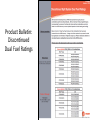
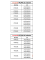
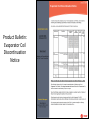
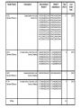
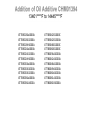
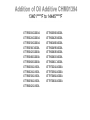
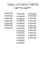
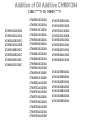
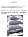
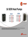
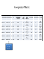
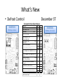
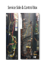
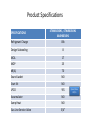
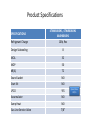
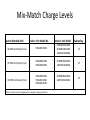
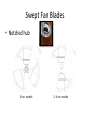
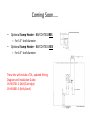
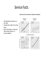
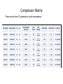
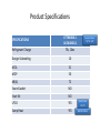
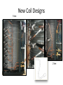
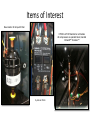
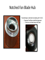
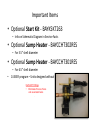
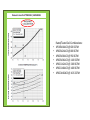
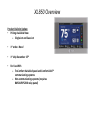
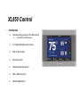
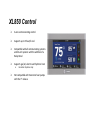
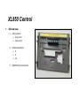
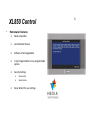
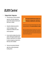
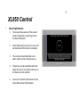
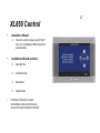
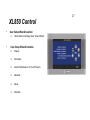
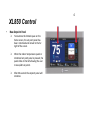
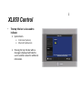
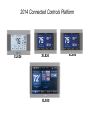
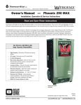
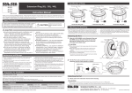
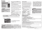
3T Tech Talk Dave Paterson and Dustin Evans January 2014 THIS DOCUMENT CONTAINS CONFIDENTIAL, PROPRIETARY OR TRADE SECRET INFORMATION OF TRANE AND IS INTENDEDFOR USE BY INDEPENDENT TRANE OR INDEPENDENT AMERICAN STANDARD HEATING & AIR CONDITIONING DISTRIBUTORS AND DEALERS ONLY. IT MAY NOT BE DISCLOSED TO ANY THIRD PARTY WITHOUT PRIOR WRITTEN CONSENT FROM TRANE U.S. INC. OR ITS AFFILLIATES. Product Bulletin: Discontinued Dual Fuel Ratings Product Bulletin: Evaporator Coil Discontinuation Notice Product Bulletin: Nexia Certified Z-Wave Siren & Strobe http://www.nexiahome.com/compatible-products/ http://www.nexiahome.com/compatible-products/ 4TTB3018AA000A 4TTB3018G1S00A 4TTB3018H1000A 4TTB3024AA000A 4TTB3024G1S00A 4TTB3024H1000A 4TTB3030AA000A 4TTB3030G1000A 4TTB3030G1S00A 4TTB3036AA000A 4TTB3036A1000A 4TTB3042D1000C 4TTB3042D1S00A 4TTB3048D1000C 4TTB3060D1000C 4TTB6036A1000A 4TTB6042A1000A 4TTB6048A1000A 4TTB6049A1000A 4TTB6060A1000A 4TTB6061A1000A 4TTB6061B1000A 4TTR3018G1000A 4TTR3024G1000A 4TTR3030G1000A 4TTR3036E1000A 4TTR3042D1000A 4TTR3048D1000A 4TTR3060D1000A 4TTR4018L1000A 4TTR4024L1000A 4TTR4030L1000A 4TTR4036L1000A 4TTR4042L1000A 4TTR6036B1000A 4TTR6042B1000A 4TTR6048B1000A 4TTR6049B1000A 4TTR6060B1000A 4TTR6061B1000A 4TTR6061C1000A 4TTR7024A1000A 4TTR7036A1000A 4TTR7048A1000A 4TTR7060A1000A 4TTM3024B1000A 4TTM3030B1000A 4TTM3042A1000B 4TTM3042A1000C 4TTM3042A1000D 4TTM3048A1000B 4TTM3060A1000B 4TTA3030AD000A 4TTA3036AD000A 4TTA3036B3000A 4TTA3036B3S00A 4TTA3036B4000A 4TTA3042AD000A 4TTA3042D3000C 4TTA3042D3S00A 4TTA3042D4000C 4TTA3048D3000C 4TTA3048D4000C 4TTA3060D3000C 4TTA3060D4000C 4TTX6024G1000B 4TTX6036H1000A 4TTX6042H1000A 4TTX6048H1000A 4TTX6049H1000A 4TTX6060H1000A 4TTX6061H1000A 4TTX8024A1000A 4TTX8036A1000A 4TTX8048A1000A 4TTX8060A1000A 4TWB3024D1000A 4TWB3036C1000A 4TWB3042B1000C 4TWB4042G1000B 4TWB3048B1000C 4TWB3060B1000C 4TWB4049E1000C 4TWB4061E1000C 4TWR3018D1000A 4TWR3024D1000A 4TWR3036C1000A 4TWR3042B1000A 4TWR3048B1000A 4TWR3060B1000A 4TWR4036D1000A 4TWR4042D1000A 4TWR4048D1000A 4TWR4060D1000A 4TWR5042G1000A 4TWR5049E1000B 4TWR5061E1000B 4TWR6024A1000B 4TWR7024A1000B 4TWR7036A1000A 4TWR7036B1000A 4TWR7048A1000A 4TWR7048A1000B 4TWR7060A1000A 4TWR7060A1000B 4TWX5042B1000A 4TWX5049E1000B 4TWX5061G1000A 4TWX6024G1000B 4TWX8024A1000A 4TWX8036A1000A 4TWX8036C1000A 4TWX8048A1000A 4TWX8060A1000A 4TWA3036B3000A 4TWA3036B4000A 4TWA3042B3000A 4TWA3042B4000A 4TWA3048B3000B 4TWA3048B4000B 4TWA3060B3000A FURN-SVB054A-EN Field reports indicate gas pressure adjustments are being made to furnace gas valves, in an effort to improve efficiency. This bulletin is to address the manufacture’s required methods of setting firing rates and gas pressure for gas furnaces. This is not to address a safety concern. FURN-SVB054A-EN It is not possible to increase efficiency by increasing the firing rate of our furnaces. Operation at higher gas inputs than stated on the rating nameplate can shorten heat exchanger life, cause safety switches to open and shut down the furnace. FURN-SVB054A-EN Any proposed methods of combustion analysis that promotes altering the firing rate to obtain a specific CO2 or Oxygen concentration levels should not be used. Altering the firing rate is not supported by this manufacturer and may result in efficiency loss, with higher fuel consumption, reduced heat exchanger life, and additional service calls for “no heat”. 16 SEER Heat Pumps XL16i 4TWX6024H1000A 4TWX6036H1000A 4TWX6042H1000A 4TWX6048H1000A 4TWX6060H1000A XR16 4TWR6024H1000A 4TWR6036H1000A 4TWR6042H1000A 4TWR6048H1000A 4TWR6060H1000A THIS DOCUMENT CONTAINS CONFIDENTIAL, PROPRIETARY OR TRADE SECRET INFORMATION OF TRANE AND IS INTENDEDFOR USE BY INDEPENDENT TRANE OR INDEPENDENT AMERICAN STANDARD HEATING & AIR CONDITIONING DISTRIBUTORS AND DEALERS ONLY. IT MAY NOT BE DISCLOSED TO ANY THIRD PARTY WITHOUT PRIOR WRITTEN CONSENT FROM TRANE U.S. INC. OR ITS AFFILLIATES. Compressor Matrix PART NUMBER MODEL NUMBER RLA LRA RECOMMENDED CAPACITOR SHELL HEIGHT SHELL C-S RESISTANCE C-R RESISTANCE OIL CAPACITY DIAMETER 5.5" COM11524 SBA020C1CPA 10.9 63 COM11525 SBA024C1CPA 12.8 68.0 35MFD 15.0 BAYCCHT302 40MFD 15.0 BAYCCHT302 1.64 1.3 21oz OIL00094 1.78 1.18 25oz OIL00094 1.60 0.92 25oz OIL00094 1.56 0.58 42oz OIL00094 1.48 0.56 42oz OIL00094 0.76 0.41 42oz OIL00094 5.5" 5.5" COM11526 SBA029C1CPA 14.1 72 45MFD 15.0 BAYCCHT302 COM11527 SBA034B1CPA 16.7 109 45MFD 16.5" BAYCCHT301 16.5" BAYCCHT301 16.5" BAYCCHT301 6.5" 6.5" COM11528 SBA040B1CPA 18.5 124 45MFD 6.5" COM11497 SBA049B1CPA 23.7 152.5 Shell Diameter C = 5.5” B = 6.5” 70MFD What’s New • Defrost Control December 3T Demand Defrost Quick Specs CNT07255 PSC Fan; 2-3 ton COMPRESSOR MNEMONIC NO. SCROLL SCROLL CNT GROUP NOMENCLATURE * SUPERSEDURE CNT 07255 07256 G01 G02 NA NA PSC ECM 1-SPD 1-SPD ≤52⁰F ≤52⁰F ≤32⁰F ≤32⁰F MIN DEFROST TIME (MINUTES) 1 1 TARGET DEFROST TIME (MINUTES) 4 4 MAX TIME OVERRIDE (MINUTES) 15 15 DEFROST TERMINATE COIL TEMPERATURE (Factory Setting) 47°F 47°F DEFROST HI TERMINATE COIL TEMPERATURE (Cut Jumper 2) 70° F 70°F 12 12 0 0 LOW AMBIENT HEAT PUMP LOCK OUT -7° F -7° F LOW AMBIENT HEAT PUMP RESUME 3° F 3° F LPCO INPUT TO CONTROL YES YES 1 1 OD FAN TYPE – PSC/ECM DEFROST ENABLED: Y = ON OUTDOOR TEMPERATURE = DEFROST PERMIT: Y = ON TEMPERATURE = SOV SWITCH-OVER DELAY DEFROST TERM. (SECONDS) DEFEAT SWITCH-OVER DELAY (SECONDS) (Cut Jumper 1) LPCO BYPASS IN/OUT DEFROST (MINUTES) * GROUP suffix for draw ing number D158283 ≤ (EQUAL OR LESS THAN) COIL AFTER CNT07256 ECM Fan; 3.5-5 ton Service Side & Control Box Service Port Product Specifications SPECIFICATIONS 4TWX6024H1, 4TWR6024H1 4A6H6024H1 Refrigerant Charge 7lb, 5oz Design Subcooling 10 MCA 14 MOP 25 dB(A) 71 Sound Jacket NO Start Kit NO LPCO YES Accumulator NO Sump Heat NO Gas Line Service Valve 3/4” Open/Close 35/55 Product Specifications SPECIFICATIONS 4TWX6030H1, 4TWR6030H1 4A6H6030H1 Refrigerant Charge 8lb Design Subcooling 8 MCA 17 MOP 25 dB(A) 70 Sound Jacket NO Start Kit NO LPCO YES Accumulator NO Sump Heat NO Gas Line Service Valve 3/4” Open/Close 35/55 Product Specifications SPECIFICATIONS 4TWX6036H1, 4TWR6036H1 4A6H6036H1 Refrigerant Charge 8lb, 14oz Design Subcooling 10 MCA 18 MOP 30 dB(A) 70 Sound Jacket NO Start Kit NO LPCO YES Accumulator NO Sump Heat NO Gas Line Service Valve 3/4” Open/Close 35/55 Product Specifications SPECIFICATIONS 4TWX6042H1, 4TWR6042H1 4A6H6042H1 Refrigerant Charge 10lb, 5oz Design Subcooling 8 MCA 24 MOP 40 dB(A) 72 Sound Jacket NO Start Kit NO LPCO YES Accumulator NO Sump Heat NO Gas Line Service Valve 7/8” Open/Close 35/55 Product Specifications SPECIFICATIONS 4TWX6048H1, 4TWR6048H1 4A6H6048H1 Refrigerant Charge 10lb, 9oz Design Subcooling 8 MCA 26 MOP 40 dB(A) 72 Sound Jacket NO Start Kit NO LPCO YES Accumulator NO Sump Heat NO Gas Line Service Valve 7/8” Open/Close 35/55 Product Specifications SPECIFICATIONS 4TWX6060H1, 4TWR6060H1 4A6H6060H1 Refrigerant Charge 10lb, 9oz Design Subcooling 8 MCA 32 MOP 50 dB(A) 72 Sound Jacket NO Start Kit NO LPCO YES Accumulator NO Sump Heat NO Gas Line Service Valve 7/8” Open/Close 35/55 Mix-Match Charge Levels System Matched with: Indoor Unit Model No. Outdoor Unit Model Subcooling 16 SEER Heat Pump (2 ton) TEM6A0C36H31 4TWX6024H1000A 4TWR6024H1000A 4A6H6024H1000A 15 SEER Heat Pump (2 ton) TEM6A0B24H21 TEM6A0B30H21 4TWR5024G1000A 4A6H5024G1000A 14˚ 15 SEER Heat Pump (3 ton) TEM6A0B30H21 TEM6A0C36H31 TEM6A0C42H41 4TWR5036G1000A 4A6H5036G1000A 14˚ All other matches must be charged per the nameplate charging instructions 13˚ Swept Fan Blades • Notched hub 5 ton models 2- 4 ton models Coming Soon….. • Optional Sump Heater - BAYCCHT302RES – For 5.5” shell diameter • Optional Sump Heater - BAYCCHT301 RES – For 6.5” shell diameter These kits will include a TDL, updated Wiring Diagram and Installation Guide: 18-HE47D1-2 (Well/Cartridge) 18-HE48D1-3 (Belly Band) Service Facts PRESSURE CURVES FOR 4TWX6024H1 & 4TWR6024H1 & 4A6H6024H1 • • • All Tested/Rated combinations are with TEM6 Heating airflow is higher than cooling airflow No Time Delay Relay is needed with TEM6 (cooling off-delay is 1.5 minutes by default) 14 SEER Air Conditioners XR14 4TTR4018L1000A 4TTR4024L1000A 4TTR4036L1000A 4TTR4042L1000A 4TTR4048L1000A 4TTR4060L1000A THIS DOCUMENT CONTAINS CONFIDENTIAL, PROPRIETARY OR TRADE SECRET INFORMATION OF TRANE AND IS INTENDEDFOR USE BY INDEPENDENT TRANE OR INDEPENDENT AMERICAN STANDARD HEATING & AIR CONDITIONING DISTRIBUTORS AND DEALERS ONLY. IT MAY NOT BE DISCLOSED TO ANY THIRD PARTY WITHOUT PRIOR WRITTEN CONSENT FROM TRANE U.S. INC. OR ITS AFFILLIATES. 10/7/2014 Compressor Matrix These are all new, 6th generation scroll compressors PART NUMBER MODEL NUMBER RLA LRA RECOMMENDED CAPACITOR SHELL HEIGHT COM11535 SBA014C1CPA 9.0 63 35MFD 15.0 COM11524 SBA020C1CPA 10.9 63 35MFD 15.0 COM11525 SBA024C1CPA 12.8 68.0 40MFD 15.0 COM11526 SBA029C1CPA 14.1 72 45MFD 15.0 COM11527 SBA034B1CPA 16.7 109 45MFD 16.5" COM11528 SBA040B1CPA 18.5 124 45MFD 16.5" COM11497 SBA049B1CPA 23.7 152.5 70MFD 16.5" SHELL DIAMETER C-S RESISTANCE C-R RESISTANCE OIL CAPACITY 5.5" 1.64 1.3 21oz OIL00094 1.64 1.3 21oz OIL00094 1.78 1.18 25oz OIL00094 1.60 0.92 25oz OIL00094 1.56 0.58 42oz OIL00094 1.48 0.56 42oz OIL00094 0.76 0.41 42oz OIL00094 BAYCCHT302 5.5" BAYCCHT302 5.5" BAYCCHT302 5.5" BAYCCHT302 6.5" BAYCCHT301 6.5" BAYCCHT301 6.5" BAYCCHT301 Product Specifications SPECIFICATIONS 4TTR4018L1 4A7A4018L1 Service Valves 3/4” & 3/8” Refrigerant Charge 4lb, 8oz Design Subcooling 10 MCA 12 MOP 20 dB(A) 72 Sound Jacket NO Start Kit NO LPCO YES Open/Close 50/70 Sump Heat NO BAYCCHT302A Product Specifications SPECIFICATIONS 4TTR4024L1 4A7A4024L1 Service Valves 3/4” & 3/8” Refrigerant Charge 4lb, 11oz Design Subcooling 10 MCA 14 MOP 25 dB(A) 72 Sound Jacket NO Start Kit NO LPCO YES Open/Close 50/70 Sump Heat NO BAYCCHT302A Product Specifications SPECIFICATIONS 4TTR4030L1 4A&A4030L1 Service Valves 3/4” & 3/8” Refrigerant Charge 5lb, 4oz Design Subcooling 10 MCA 17 MOP 25 dB(A) 73 Sound Jacket NO Start Kit NO LPCO YES Open/Close 50/70 Sump Heat NO BAYCCHT302A Product Specifications SPECIFICATIONS 4TTR4036L1 4A7A4036L1 Service Valves 3/4” & 3/8” Refrigerant Charge 6lb, 1oz Design Subcooling 10 MCA 18 MOP 30 dB(A) 73 Sound Jacket NO Start Kit NO LPCO YES Open/Close 50/70 Sump Heat NO BAYCCHT302A Product Specifications SPECIFICATIONS 4TTR4042L1 4A7A4042L1 Service Valves 7/8” & 3/8” Refrigerant Charge 6lb, 7oz Design Subcooling 12 MCA 22 MOP 35 dB(A) 72 Sound Jacket NO Start Kit NO LPCO YES Open/Close 50/70 Sump Heat NO BAYCCHT301A Product Specifications SPECIFICATIONS 4TTR4048L1 4A7A4048L1 Service Valves 7/8” & 3/8” Refrigerant Charge 6lb, 9oz Design Subcooling 10 MCA 24 MOP 40 dB(A) 72 Sound Jacket NO Start Kit NO LPCO YES Open/Close 50/70 Sump Heat NO BAYCCHT301A Product Specifications SPECIFICATIONS 4TTR4060L1 4A7A4060L1 Service Valves 7/8” & 3/8” Refrigerant Charge 7lb, 10oz Design Subcooling 10 MCA 31 MOP 50 dB(A) 72 Sound Jacket NO Start Kit NO LPCO YES Open/Close 50/70 Sump Heat YES BAYCCHT301A New Coil Designs 5 ton 2 ton Items of Interest New location for ship-with Drier HPCO & LPCO Standard on all models All compressors are painted black, branded Climatuff™ /Duration™ 2-pole on 5-ton Notched Fan Blade Hub Transitioning to notched hub starting with 14 A/C. • Ensures Fan Motor shaft-flat alignment • Servicer can break away with twist Important Items • Optional Start Kit - BAYKSKT263 – Info on Schematic Diagram in Service Facts • Optional Sump Heater - BAYCCHT302RES – For 5.5” shell diameter • Optional Sump Heater - BAYCCHT301RES – For 6.5” shell diameter • 14 SEER program – Units designed without Pinch-Off tubes FasTest XT Fittings • Eliminates Process Tubes and associated leaks . Pressure Curves for 4TTR4018L1 / 4A7A4018L1 • • • • • • • Rated/Tested Coil Combinations: 4PCXBU18AC3 @ 600 SCFM 4PXCBU24AC3 @ 800 SCFM 4PXCBU30AC3 @ 950 SCFM 4PXCBU36AC3 @ 1100 SCFM 4PXCCU42AC3 @ 1300 SCFM 4PXCCU48AC3 @ 1400 SCFM 4PXCDU60AC3 @ 1615 SCFM XR14/Silver 14 – Air Conditioners First ship date: October 27, 2014 Single Stage Climatuff ™ & Duration ™ Compressors All Aluminum Spine Fin ™ Coils Coil only: 14SEER, 12.2 EER Hi Eff Furnace: 15 SEER, 12.5 EER Hi Eff Air Handler: 15.5 SEER, 13 EER • Questions? XL850 Control Introduction XL850 Overview Product Bulletin Update • Pricing Available Now Single Lot and Case Lot • 1st order.. Now! • 1st ship December 15th • For Use With TruComfort Variable Speed and ComfortLinkII™ communicating systems Non-communicating systems (requires BAY24VRP52DB relay panel) 53 XL850 Overview Product Bulletin Update • Record the 850’s AUID number and associated customer contact information so they may have access to the control’s data after homeowner approval when the dealer portal is launched • Read the Installer and User Manual 54 XL850 Delivered Value Key Differentiated Features • Exclusive Built In Nexia™ Home Intelligence Z-Wave Bridge • Exclusive, Easy to Set Up Wi-Fi or Ethernet Connectivity • Complete Connectivity Nexia™ Home Intelligence Ready Remote Climate Control for Homeowner Nexia Diagnostic Data for Dealer… 2015 • Easy to Install and Configure Installation Wizard… User Set Up Wizard… 55 XL850 Control • Introduction Communicating version of the 824 control Compatible w/VSPD systems 4.3” High Definition Color Screen Built-in Wi-Fi radio Ethernet option Onboard Humidity Sensor Micro-USB connector Nexia Bridge Built-In XL850 Control 3-wire communicating control Supports up to 5 heat/2 cool Compatible with all communicating systems and 24-volt systems with the addition of a Relay Panel Supports gas/oil, electric and hydronic heat Forced air hydronic only Not compatible with Ameristar heat pumps with the 1st release XL850 Control • 850 sub-base Temp sensors Remote RS1 Outdoor ODT HVAC connections D R B/C RJ45 Ethernet connection XL850 Control • Homeowner Features Nexia compatible Local Weather feature Software is field upgradable 7-day Programmable or non-programmable options Security Settings Screen Lock Guest Access Setup Wizard for user settings 4 XL850 Control • Displayed Indoor Temperature On initial startup or after an extended power loss, the indoor temperature sensor of the control may require up to 60 minutes to stabilize During this stabilization period the control may display an indoor temperature well below the actual indoor temperature An insert will be included with each 824 control informing the installer that this behavior is expected and to not calibrate the indoor temperature during the first 60 minutes after installation The insert also provides information about the new Smart Optimization learning routine 3 XL850 Control • Smart Optimization To increase the accuracy of the sensed indoor temperature a learning routine has been developed Smart Optimization only occurs once and will take about 90 minutes to complete The routine will automatically occur about 18 hours after initial power-up The process can be cancelled which will delay the routine for another 18 hours or the feature can be disabled To access the Smart Optimization screen, select Menu>Smart Optimization XL850 Control • 850 Hang Tag One of the lessens learned of the 950 program is that most customers don’t understand all the features within the control For this reason we developed a User Wizard to assist the consumer in customizing how the control operates A laminated hang tag will be shipped with each control prompting the consumer to navigate to the User Setup Wizard to finalize the setup of the control The hang tag can be affixed to the control for installations where the consumer is not home when the job has been completed 1 17 XL850 Control • Installation Wizard • • Once the control powers up for the 1st time, the Installation Wizard launches automatically Installation Wizard includes: Date & Time Installer Setup Reminders Dealer Code Installation Wizard is located Home>Menu>Service>Technician Access>Proceed>Installation Wizard 17 XL850 Control • User Setup Wizard Location • Home>Menu>Settings>User Setup Wizard User Setup Wizard includes: Display Schedules Guided Schedules or 1-Touch Presets Network Nexia Weather 4 XL850 Control • New Setpoint Panel To maximize the limited space on the home screen, the set point panel has been minimized and moved to the far right of the screen When the indoor temperature panel or minimized set point panel is pressed, the panel slides to the left allowing the user to view/edit set points After 60 seconds the setpoint panel will minimize 2 XL850 Control • The top title bar is also used to indicate: System Alerts Critical alert (red icon) Major alert (yellow icon) Pressing the top title bar while a message is displayed will take the user to another screen for additional information 2014 Connected Controls Platform XL624 XL824 XL850 XL950 67 The 2015 Training schedule has been posted at: www.tranepennohio.com Sign Up early to get in!! Questions?? *6 to Unmute your Line OR Type a Question in