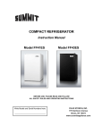
1
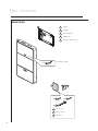
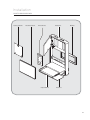
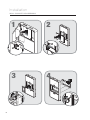
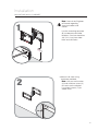
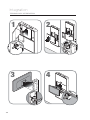
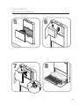
Non-Locking and
PIN Code Locking Cabinet
Wall Mounted Workstation
Manual
Warnings
IMPORTANT – Indicates a situation that does not present any hazard but is
very important in maintaining a well functioning workstation.
ATTENTION – Consult manual to avoid a potentially
hazardous situation which may result in minor or
moderate injury.
• Contact the facility Engineer of Record for direction on mounting locations and
methods prior to installing any wall tracks or equipment.
ELECTRICAL – Indicates an impending electrical hazard
which, if not avoided, may result in personal injury, fire and/or death.
• The supplied power cord is rated for medical use. Connecting the cord to an outlet that
is not medical grade (indicated with a green dot) will not ensure grounding protection
(Locking Cabinet Only).
• Power cord, USB extension, and workstation are for INDOOR use only. DO NOT
OPERATE OUTDOORS.
• Keep power cord away from water. DO NOT PLUG CORD INTO OUTLET IF WET.
• DO NOT OPERATE PRODUCT IF WET. If the WORKSTATION becomes wet, unplug it
immediately, wipe off any excess liquid, and allow it to dry before using again.
• Inspect power cord before integration. DO NOT USE POWER CORD IF DAMAGED.
• Fully insert power cord plug into outlet. DO NOT unplug by pulling on cord. DO NOT
remove, bend or modify any metal prongs or pins of power cord.
• DO NOT use excessive force to make mechanical or electrical connections.
• DO NOT use an electrical extension cord with your workstation.
• DO NOT use a flammable cleaner on the station as it can result in fire or explosion.
Transport/Storage
• The shipping weight of this unit is approximately 86 lbs (39 kg).
Use proper lifting techniques to prevent injury.
• Care should be taken to transport and store this system within a temperature range of
32ºF to 90ºF (0ºC to 32ºC); Humidity 20% RH to 95% RH non-condensing.
2
Table of Contents
Box Contents.......................................................................................................... 4
Installation ............................................................................................................. 6
Parts Breakdown....................................................................................................... 6
Wall Cabinet Disassembly ................................................................................ 6
Mounting Wall Cabinet ..................................................................................... 7
Wall Cabinet Resassembly ............................................................................... 8
Integration ........................................................................................................... 10
Technology Schematic ................................................................................... 10
Specifications ................................................................................................ 11
Technology Integration............................................................................................. 12
USB Cable Locations...................................................................................... 14
Software Installation ........................................................................................... 15
Programmable Controller/Lock........................................................................... 17
Maintenance ........................................................................................................ 20
Service ................................................................................................................. 22
Warranty............................................................................................................... 23
Box Contents
WORKSTATION
B
A
A
Cabinet
B
Template
C
CPU Security Key
D
Hardware Kit
E
Cabinet Lock Override Key
Taped inside of cabinet
x2 C
D
E
x4 F
x4 G
x4 H
4
F
Wood Screw
G
Machine Screw
H
Wall Anchor
Installation
PARTS BREAKDOWN
Technology Bracket
Tinted Monitor Cover
Monitor Bracket
Keyboard Drawer
Wall Cabinet
Wall Cleat
Mouse Pad
5
Installation
WALL CABINET DISASSEMBLY
2
1
2
2
1
1
3
4
2
2
1
1
6
Installation
MOUNTING WALL CABINET
Note: Consult the Engineer
of Record regarding
structural codes and
utilities.
1
Use the mounting template
(B) to determine drill hole
locations. Set line should be
48" (121.9 cm) from floor.
Mark and drill holes.
B
4
(12 8"
1.9
cm
)
o Mount wall cleat using
hardware provided.
Note: Use part wall anchor
(H) and machine screw (G)
for steel stud installation.
Use wood screws (F) for
wood studs.
2
x4
7
Installation
WALL TRACK INSTALLATION
o Hang wall cabinet (A) on wall
cleat and secure with
screws.
3
1
A
2
WALL CABINET REASSEMBLY
2
1
3
1
1
2
8
2
9
Integration
TECHNOLOGY SCHEMATIC
Monitor
CPU
Keyboard
10
Mouse
Integration
SPECIFICATIONS
Power Cord (locking cabinet only) 1.5' (45.0 cm) length, Medical Grade NEMA
Right Angle Plug, 3x NEMA Receptacles,
125V 50/60Hz
250W max
USB Cables
2 – USB 2.0 Type A Male to Type A Female
Extension Cables
Monitor Bracket
25 lbs (11.3 kg) max; VESA 75 mm & 100
mm
Keyboard Drawer
Accommodates 1.75" H x 18" W x 8" D (4.5
cm x 45.7 cm x 20.3 cm) USB keyboard
Work Surface
20.38" W x 10" D (51.8 cm x 25.4 cm)
Mouse Pad
10" W x 10" D (25.4 cm x 25.4 cm)
Technology Cabinet
Accommodates CPUs up to 11" W x 11" H x
2.9" D (27.9 cm x 27.9 cm x 7.4 cm)
11
Integration
TECHNOLOGY INTEGRATION
1
2
2
3
1
2
1
4
3
1
1
2
2
12
Integration
TECHNOLOGY INTEGRATION
6
5
2
7
8
1
2
13
Integration
USB CABLE LOCATIONS
1
o Two USB cables are located in the rear
corner of the keyboard tray. These are
routed to the technology box area and
should be plugged into the CPU.
14
o Three USB cables are located in the
technology box area. These should be
connected to CPU to provide power for
the Task Light, Keyboard, and Monitor.
Software Installation
USB TASK LIGHT SOFTWARE
Preparation
Uninstall any previous drivers that may have
been installed for the USB task light. (If USB
device has not been installed previously, skip
to installation section)
1. Start > Control Panel > System
2. Click on the Hardware tab
3. Select the Device Manager button
4. Scroll down to Ports (Com & LTP) Look for
a device
named AT90USBxxx CDC USB to UART
MGM (Com XX).
5. Double click on this device and click the driver
tab at the top.
6. Click Uninstall driver and accept the removal.
7. Restart Computer.
Note** - If the drivers did not install correctly the
first time it may be listed in the “Other” device
list usually indicated with a yellow Asterisk
symbol.
15
Software Installation
USB TASK LIGHT SOFTWARE
Installation
(DO NOT plug USB cable in at this point):
1. Run RubbermaidLCDSecureIT.exe setup
file.
2. Once installation is complete plug in
USB to an open port and wait for driver
request.
3. The USB Driver is located within the files
provided (at90usbxxx_cdc.inf)
4. After the USB drivers have been installed
you can setup the software preferences.
(see below)
Software Setup
There are 4 options that are available when the keyboard is closed:
• None (No action taken)
• Immediate Blank Screen
• Immediate Screen Saver (Select On resume, Password protect under screen saver
options if user id and password is required)
• Immediate lock computer screen
You can adjust the duration of time the light will stay on at any given instance. (Default
is 5 minutes). The password section is not applicable in this situation (Non-Locking
Cabinets).
Shutdown the software
Upper right-hand corner is a “shutdown” button to completely close the software. If you
close the window it will be minimized to the system tray.
The green LED will flash indicating that
erasing is complete
16
Programmable Controller/Lock
PIN CODE LOCKING CABINET ONLY
Green LED
Lock Button
PROGRAMMING FUNCTIONS
1
6
Red LED
2
7
3
8
4
9
Numeric Buttons
LOCK
5
CLEAR
0
Clear Button
In normal operation the user will enter a
4-digit access code. Once a numeric key
is pressed, the green LED will light. The
user will then enter the remaining 3-digits of
their code. If the access code is accepted,
the green LED will blink and the door
actuator will be released for the time period
specified. If the password is not accepted,
the red LED will blink.
If a mistake is made during code entry, the
‘*’ key can be used to clear previous key
strokes and start over. This will also turn off
the green LED. Once a key is pressed, the
keypad will wait 30 seconds for the next
input. If 30 seconds elapse with no input,
the keypad will clear previous key strokes.
The green LED will turn off and the red LED
will flash.
Note: Once a function code or
supervisor code has been accepted,
the keypad will wait 30 seconds for the
next key input. If 30 seconds elapse
with no input, the red LED will flash
and the keypad will return to normal
mode. The ‘Lock’ key will be inactive
during keypad programming mode.
Serial communication will be inactive
during keypad programming mode.
During serial communication, all keypad
buttons will remain inactive.
All programming functions are initiated by
entering the ‘*’ key, then the supervisor
code, followed by the ‘*’ key. Next, the
programming code is entered, followed
by the ‘*’ key. See the table below for
programming codes.
0*
1*
2*
3*
4*
5*
6*
Restore default settings
Erase all user codes
Remove specified user code
Add user code
Program re-lock time
Program new supervisor code
Program keypad serial number
LED Light Status
Solid Green
Waiting for user input
Flashing Green
Released door, command accepted
Solid Red
Serial communication, keypad inactive
Flashing Red
Lock command, input error
Unlocking the Control Pad
# # # #
4-digit user code
The green LED will flash and the door
actuator will be released.
Restore Default Settings
The controller can be set to its factory
default settings. To restore the default
settings:
# # # #
0
4-digit supervisor code
Function
The green LED will flash indicating that
programming is complete. The table
below lists the default parameters.
Default Settings
User code
8294
Supervisor code
7183
Door re-lock time
10 seconds
Keypad serial number
00-00000-WC-01
Note: Restoring the default settings will
also erase all user codes except the
default code.
17
Programmable Controller/Lock
PIN CODE LOCKING CABINET ONLY
Erase All User Access Codes
# # # #
1
4-digit supervisor code
Function
The green LED will flash indicating that
erasing is complete.
Program Door Release Time
The length of time the door is released
can be programmed from one second to
90 minutes. To change from the default
of ten seconds:
# # # #
Remove User Access Code
# # # #
4-digit supervisor code
2
Function
4
# # # #
4-digit user code
The green LED will flash indicating that
erasing is complete. If the code is not
stored in memory, or an invalid key is
pressed (‘*’, ‘Lock’), the red LED will flash.
# # # #
Function
4-digit supervisor code
MMSS
(Minutes/Seconds)
The green LED will flash indicating
programming is complete. If an invalid key
is pressed (
, ‘Lock’) , the red LED will
flash.
‘*’
Note: Enter the desired amount of time
in the format ‘MMSS’ where :
MM is the number of minutes and SS is
Add User Access Code
the number of seconds.
128 user access codes can be
programmed into the keypad. The user
access codes can be any combination of
digits. To program an access code:
Maximum time allowed is 90 minutes.
Any time above the maximum will
default to 90 minutes.
Program Supervisor Code
# # # #
4-digit supervisor code
3
Function
# # # #
4-digit user code
The green LED will flash indicating
that programming is complete. If the
user memory is full, or an invalid key
is pressed (‘*’, ‘Lock’) , the red LED
will flash. If the code entered is already
stored in memory, the green LED will
flash as normal.
# # # #
5
# # # #
Function 4-digit supervisor code
4-digit supervisor code
The green LED will flash indicating that
programming is complete. If an invalid key
is pressed (‘*’, ‘Lock’) , the red LED will
flash. If the code entered is already stored
in memory, the green LED will flash as
normal.
Program Keypad and Serial Number
# # # #
4-digit supervisor code
6
Function
# # # # # # #
7-digit serial number
The green LED will flash indicating that
programming is complete. If an invalid key
is pressed (‘*’, ‘Lock’), the red LED will
flash.
18
19
Maintenance
DO NOT use the workstation if pieces are missing or the unit is damaged. In
these cases, immediately contact Rubbermaid Customer Service for more
information: 1-888-859-8294.
Cables: Always keep the cables neatly organized and be sure to route cables away
from moving components with wire ties or
cable clips.
Power Cord (locking cabinet only): Periodically inspect power cord and plug to ensure
plug is not bent and cable is not frayed.
CLEANING
CAUTION: Because of the close proximity of electrical power and equipment,
flammable cleaners should never be used on the workstation.
• Verify that your workstation is unplugged from the wall outlet before cleaning.
• Allow your workstation to dry completely before plugging the power cord into a wall
outlet.
• When cleaning the workstation, wipe surface with a damp cloth and thoroughly dry.
• Never cover the workstation or its components with liquid or allow liquids to flow into
the workstation.
• Never use steel wool or other abrasive material as these could damage the surface
finish.
• Before using any cleaner on the workstation, first test on a small area to ensure that the
surface is not harmed.
• These guidelines cannot guarantee infection control. The hospital’s Infection Control
Administrator should be consulted regarding cleaning procedures and schedules.
• Clean plastic components with diluted, non-abrasive solutions. Suggested cleaners
are water, soap, diluted bleach and alcohol solutions.
• Remove pen and dry erase marker stains with a soft cloth and 91% isopropyl alcohol.
• Remove iodine stains with a soft cloth and any cleaners
suggested above.
DO NOT use the following chemicals to clean your workstation: acetone, mineral
spirits, abrasive cleansers, paint thinner or any other harsh or toxic chemicals.
WOOD PANEL CARE
Harsh, abrasive and undiluted cleaning products may cause damage to Deco Lam and
the contact adhesive.
Pine Sol and Simple Green are cleaners that have been approved for use on Deco Lam.
A 30-1 ratio of water to cleaner is highly advised. Recommend water and a clean towel
as a cleaning alternative to homeowners.
20
Troubleshooting
Problem
Solution
Keyboard
mechanism folds
down too fast or
too slow.
Remove the right side extrusion and locate the adjustment
screw on the damper. To slow it down, turn screw to right.
Top door needs
adjustment for
alignment.
Open the top door and locate the 2 hinges on the left side. To
adjust the door up or down use the inside screw of the hinges.
Task Light is not
turning on.
Remove the right side extrusion and make sure the light
assembly cables with orange ends are secure on the switch.
To make it faster, turn screw to the left.
To adjust the door right or left use the outside screw on the
hinges.
21
Service
SERVICE REQUEST
Contact your IT department, or file a service request at our website: www.
rubbermaidhealthcare.com/service.
SERVICE LEVEL COMMITMENT
Rubbermaid Healthcare is committed to providing best-in-class service. This document
details our standard warranty and instructions on how to request service using our
customer support system.
Warranty
LIMITED WARRANTY FOR WALL MOUNTED WORKSTATIONS
Rubbermaid Healthcare is pleased to offer a five-year warranty on durable components
and a two-year warranty on electronic
components.
If during the warranty period this Rubbermaid Healthcare product proves defective in
materials or workmanship under normal use by the original purchaser, please contact
Rubbermaid Healthcare technical support at www.rubbermaidhealthcarel.com/service
(please be sure to complete all information, including product serial number, description
of the issue, and full contact information). Rubbermaid Healthcare will determine, at its
sole discretion, how to best address your warranty issue, which may include sending
you a replacement part covered under warranty or for sale. Rubbermaid Healthcare
reserves the right to require proof-of-purchase prior to honoring any warranty request.
This warranty does not cover product abuse, modification, failure to adhere to product
instructions, or improper operation/misuse. Rubbermaid Healthcare SHALL NOT BE
LIABLE FOR ANY CONSEQUENTIAL OR INCIDENTAL DAMAGES WHATSOEVER.
Some states do not allow the exclusion or limitation of incidental or consequential
damages, so the above limitation or exclusion may not apply to you. This warranty gives
you specific legal rights and you may also have other rights which vary from state to
state or country to country.
Service Details
Consumable components are not covered under warranty and include:
• Side Extrusions
• Cable anchors
• Backboard
• Mouse Tray
All other standard components will be replaced under the applicable warranty following
a filed service request. If the service request is received prior to 10 am EST, replacement
parts will ship next business day. Requests filed after 10 am EST will be fulfilled with parts
shipped in 2 business days. All replacement parts will ship via ground carrier.
22
REVISION HISTORY
Revision
Date
Description of Changes
A
10/2010
Initial Release
B
02/2013
Change Logos and text references to Healthcare
Add revision history table
Change to half page format
23
1-888-859-8294
www.RubbermaidHealthcare.com
2/2013 Part # 1793163 Rev. B Wall Mounted Workstation User Manual
© Rubbermaid Healthcare
Huntersville, NC 28078