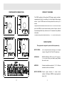
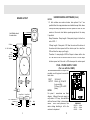
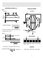
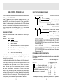
1
WARRANTY
By this Consumer Guarantee Greenwich Instruments Limited guarantees this product
to be free of defects in materials and workmanship at the time of its original purchase
from the Retailer for the period of one year. If during this period of guarantee the
product proves defective due to improper materials or workmanship Greenwich
Instruments will without charge for labour or parts repair or (at its option) replace this
product or its defective parts on the conditions set out below.
1. The customer will not alter, adapt, change or in any way adjust the product, except
as detailed in this manual.
2. This guarantee does not cover:
i) Maintenance or replacement of parts due to fair wear and tear.
ii) Home service or transport costs to the Dealer.
iii) Damage to this product resulting from a) abuse or misuse by the customer
including failure to follow Greenwich Instruments instructions in the user manual
or b) the installation or use of the product in a manner inconsistent with the
technical or safety standards in force at the time.
UK
Greenwich Instruments Ltd
The Crescent,
Main Road,
Sidcup,
Kent, DA14 6NW.
Tele: 020 8302 4931
Fax: 020 8302 4933
USA
Greenwich Instruments (USA)
Huntersville, P.O. Box 696,
NC, 28070.
Tele: (704) 875 8490
Fax: (704) 875 2801
1 800 476 4070
Web Site: www.greenwichinst.com
ISSUE 2.1
SEPTEMBER 1996
GSM5
INTELLIGENT RS232C TO 4 PHASE
STEPPER MOTOR DRIVER CARD
GENERAL NOTES
CONTENTS
PAGE
PRODUCT OVERVIEW
2
SPECIFICATION
2
BOARD LAYOUT
3
MOTOR DRIVE SCHEMATIC
4
SWITCH SETTINGS
4
DIMENSIONS
4
SOFTWARE COMMANDS
1
The stepper motor chosen for use with the GSM5 must be fully
compatible with Bipolar drivers.
2
Motor torque is motor current and motor speed related. Torque is
proportional to current and inversely proportional to speed.
3
The effective motor impedance is proportional to the load and the
speed of the motor.
4
The GSM5 will supply sufficient current for motors specified at 5
Amp / phase. Motors with higher current requirements can be driven
but they will not run at full power.
5
Ramps are used to provide increased starting torque and to
overcome motor resonance.
6
Current boost is dependent upon the setting of Pots 2 & 3 and is
available for the length of the ramp only.
7
When adjusting Pots 2 & 3 it is recommended that the initial winding
current is set at less than the value recommended for the motor and
that the motor is driven at this current whilst the motor temperature
is monitored. Avoid running the motor at high temperatures. (See
motor manufacturers specification).
8
Stepper motor drivers generate large amounts of RFI and should be
enclosed in an adequately screened enclosure, having good
ventilation.
9
The GSM5 gets hot and generates high discharge voltage. Take all
reasonable precautions when using.
5-6-7
PROGRAMMABLE MOTOR SPEED CONTROL
6
ON BOARD SETTINGS
7
WARNINGS AND SAFETY INFORMATION
8
8-9
USING CONTROL PROGRAM
UNDER STANDING SOFTWARE COMMANDS
10-11-12
V REF SETTINGS
12
POWER SUPPLY UNIT
12
STEPPER MOTOR CONNECTIONS
13
GENERAL NOTES
14
WARRANTY
Back Page
Please read this manual fully before attempting to connect the
GSM5 to the stepper motor.
Please read WARNINGS AND SAFETY INFORMATION on page
1
14
STEPPER MOTOR CONNECTIONS
PRODUCT OVERVIEW
The GSM5, together with the optional PSU5 power supply, provides a
comprehensive facility for controlling 4 or 8 wire Bipolar driven stepper
motors. Up to 4 GSM5 cards can be daisy-chained to control up to 4
motors.
Simple software commands can be sent from a PC via the RS232 serial
port to the GSM5 to control motor direction, number of steps, start and
stop ramp length and slope, motor current. All commands carry address
information.
* CENTRE WIRES NOT CONNECTED
On board settings include card address (0, 1, 2, 3) motor current (set to
SPECIFICATION
This equipment is designed to operate in half step mode only.
MOTOR DRIVE:
4 or 8 wire bipolar current switching, up to 5 ampere
/ phase Voltage 40 to 80 Volts DC (maximum).
INTERFACE:
RS232C 9600 Baud, DTE via 9 pin “D” connector,
Tx, Rx & GND active (Null modem) daisy-chained
from card to card.
ADDRESS:
On board card address selection 0, 1, 2, 3. Software
commands include card address.
MOTOR CONTROL: Current, speed, direction, ½ current, boost,
number of half steps (0-99999), ramp (length and
slope), limit.
13
2
UNDERSTANDING SOFTWARE (Cont.)
BOARD LAYOUT
NOTES
1. If limit switches are used and motor drive options E or F are
specified then the ramp parameters are disabled except that, where
a ramp has been programmed, the motor speed will start at, and
Motor
Limit Switch closed
for motor drive.
remain at, the motor start datum speed appropriate to the ramp
2. specified.
Ramp Parameter. Ramp length ÷ Ramp rate (slope) is limited to a
ratio of 200 : 1
0V Motor
If Ramp length ÷ Ramp rate > 200 then the motor will be driven at
B2 B1 A2 A1
the motor start datum speed until the ratio is equal to or less than
40 - 80 Volt Motor
200 and then the ramp up will apply.
Limit
Logic 0V
Logic 12V
Logic 0V
Therefore if a ramp length of 500 half steps is chosen with a rate
of 2 the ratio will be 250 and the motor will run for 100 half steps
at datum speed until the ratio is 200 whereupon the motor speed
PSU5 - POWER SUPPLY CARD
(For use with the GSM5)
Fan
Pot 2
OR1
OR1
Two transformer isolated DC outputs are
provided, one for logic and a second for
motor drive.
Dip
Switch
Pin 1 connected to 12
VoltHost Rx
Tx
GND
INPUT
OUTPUT
Pot 3
Pot 1
9 way Serial
9 way Serial
12345678
23 5
GND
Tx
Rx
3
Next
240 Volt AC
250 mA., @ 12 Volt DC
(Logic and Fan)
3.2 Amp., @ 70 Volt DC
(Motor)
NOTES
For pinout / connections see block
diagram. Although the motor supply is
only rated at 3.2 Amp., this should be
sufficient for most 5 Amp. / phase stepper
motors. Short circuit protection, and
mains voltage shielding is left to the
customer to implement.
12
N
E
L
DIMENSIONS
LENGTH......160mm
WIDTH.........100mm
HEIGHT.........55mm
UNDERSTANDING SOFTWARE (Cont.)
MOTOR DRIVE SCHEMATIC
RAMPS
( One Phase )
>
MOTOR SPEED
RAMP-UP
LENGTH
RAMP-DOWN
RATE
POT 1
(MOTOR
SPEED
SETTING)
MOTOR
START
DATUM
0
SWITCH
SWITCH
>
NUMBER OF HALF STEPS SELECTED
MOTOR
CONTROL
CONTROL
WINDINGS
CONTROL
MOTOR START DATUM SPEED
= MOTOR MAXIMUM SPEED X 48
(
+
SWITCH
)
RAMP LENGTH
RAMP RATE *
* If the slope of 0 is specified then Ramp Rate = 256 otherwise the rate
48
SWITCH
CONTROL
is as programmed by the F command.
0.1 R
REFERENCE
SENSE AMP
EXAMPLE
RAMP LENGTH = 300
FULL MOTOR SPEED (POT 1)
SWITCH SETTINGS
ON
ON
48 +
11
1234
>
>
>
>
1234
>
>
1234
LIMIT DETECT LIMIT DETECT ADDRESS = 3 ADDRESS = 1 ADDRESS = 2 ADDRESS = 0
ENABLED
DISABLED
For the example above, if motor speed set at 400 half steps / second,
MOTOR START DATUM SPEED = 400 X 48 = 19200 = 130 Half Steps / Sec.
48 + 300
148
3
1234
>
>
LENGTH
( RAMP
RAMP RATE )
1234
>
>
MOTOR START DATUM SPEED = MOTOR MAX. SPEED (POT 1 SETTING) X 48
1234
>
>
MOTOR START DATUM
>
>
Y=3
(RAMP RATE)
DIMENSIONS
Length = 210mm
Width = 100mm
4
height = 75mm
SOFTWARE COMMANDS
All software commands, sent via the RS232 interface , are of the format
- number, command letter, address (0, 1, 2, 3, ) followed by carriage
return <CR> or linefeed . The card will echo back via the RS232 the
command letter and the card address.
SOFTWARE OPTION COMMANDS
The following commands select card parameter options associated with
motor current, ½ step, ramp length and slope. (If not specified default
settings would apply - See page 7)
u w x y
D o <CR>
MOTOR CONTROL OPTIONS
Carriage return / linefeed
Address of card (0, 1, 2, 3,)
Command letter (Option D)
(Any character = ½ step)
Current boost for ramp length (0 = NO 1 = YES)
Revised motor current when stopped (0 = NO 1 = YES)
Motor current off when stopped (0 = NO 1 = YES)
Current boost when running (0 = NO 1 = YES)
UNDERSTANDING THE SOFTWARE COMMANDS
There are two motor drive option commands, options D and F.
Option D has 5 sub-options
Sub-option “u” selects 100% motor current when running.
(If not
selected motor runs at 66%).
Sub-option “w” selects motor current Off when motor stopped.
Sub-option “x” selects ½ motor current when motor stopped.
Note: If both options “w” and “x” are selected then option “w” will override
option “x”.
Sub-option “y” selects current boost for ramp length.
All sub-options are selected / deselected by 1 or 0. 1 = select 0 =
Option F has two sub-options
Sub-option “xxx” can be specified between 001 and 999 to set the
length of the ramp, (number of ½ steps)
Sub option “y” can be specified between 1 and 9 to set the slope of
the ramp.
(See page 11 for further explanation of ramp settings).
x x x y F o <CR>
SELECT RAMP LENGTH AND SLOPE
Carriage return / linefeed
Address of card (0, 1, 2, 3)
Command letter (option F)
0 - 9. Rate (slope) of ramp
0 - 999. Length of ramp (half steps)
B o <CR>
POLL SPECIFIED CARD
Carriage Return
Address of Card (0, 1, 2, 3)
Command Letter (Option B)
This command polls the card specified at address entered and returns
an ID message plus limit switch status.
e.g. B GSM5 999 JUN 95
L/F C/R or B GSM5 999 JUN 95 Limit Open L/F C/R
5
There are four movement command options A, C, E, G.
A and E give anticlockwise movement.
C and G give clockwise movement.
Command option A specifies anticlockwise movement for 1 to 99999
half steps
Command option C specifies clockwise movement for 1 to 99999
half steps
Command options E and G specifies anticlockwise or clockwise
movement for 1 to 99999 half steps or until the limit switch opens,
which ever event happens first. (No Ramp, stays at start speed).
10
USING CONTROL PROGRAM (Cont.)
To run the software in the normal control mode, enter the following at the
DOS prompt : C:\> GSM5TERM
When the software first runs, it sends ID requests to each of the four
possible GSM5 units which could be connected. If any respond, this is
noted and a status message is printed showing which GSM5 addresses
are active. The last GSM5 which responded, becomes the default one. To
select a different GSM5, use the number keys 0,1,2 & 3. If the requested
GSM5 is not active, an error message will be displayed.
SELECT MOTOR MOVEMENT COMMANDS
x x x x x A o <CR>
MOVE ANTICLOCKWISE
Carriage return / linefeed
Address of card (0, 1, 2, 3)
Move anticlockwise
Number of half steps (0 - 99999)
x x x x x C o <CR>
MOVE CLOCKWISE
Carriage return / linefeed
Address of card (0, 1, 2, 3)
Move clockwise
Number of half steps (0 - 99999)
USING THE SOFTWARE
Each of the GSM5 commands has been assigned to a function key as
follows:
Command
Key
Purpose
A
F1
Move Anticlockwise
C
F2
Move Clockwise
E
F3
Move Anticlockwise or until limit switch operates
G
F4
Move Clockwise or until limit switch operates
D
F5
Set-up Motor control options
F
F6
Set-up Ramp length and slope
Each of the above commands will ask for any required parameters and
will wait until the command has finished and the GSM5 is ready for another
command before continuing.
An additional mode is included in the software in which the motor can be
driven using the left and right cursor keys and displays the total offset from
the start position. Each press of the left or right cursor keys moves the
motor 10000 half steps in the chosen direction (left cursor = clockwise,
right cursor = anticlockwise). The number of half steps can be changed
using the PgUp and PgDn keys. The total number of half steps moved is
displayed with the direction. It also allows the motor to be automatically
moved back to the “zero” reference point. This is a simple way of checking
the repeatability of the mechanical system attached to the motor.
9
x x x x x E 0 <CR>
MOVE ANTICLOCKWISE
SPECIFIC NUMBER OF HALF STEPS (0-99999) OR UNTIL LIMIT
SWITCH OPERATES. No Ramp, stays at start speed. (See Ramp
Parameters page 11)
x x x x x G o <CR>
MOVE CLOCKWISE
SPECIFIC NUMBER OF HALF STEPS (0-99999) OR UNTIL LIMIT
SWITCH OPERATES. No Ramp, stays at start speed. (See Ramp
Parameters page 11).
PROGRAMMABLE MOTOR SPEED CONTROL
Programming command H has been assigned to provide seven programmable
motor speeds.
The format of the command is :Motor speed settings are:x H o <CR>
Carriage return/Linefeed
Address of Card (0, 1, 2, 3)
Command letter (Option H)
0 -7 Motor speed
0 = Speed as set by Pot 1
1 = 4,800 half steps per second
2 = 2,400
ditto
3 = 1,200
ditto
4 = 600
ditto
5 = 300
ditto
6 = 150
ditto
7 = 75
ditto
The default/power on setting is 0; speed setting defined by POT 1 adjustment.
6
GSM5TERM>EXE Software Control of Motor Speed
DEFAULT SETTINGS
When the program GSM5TERM is run, or GSM5TERM TESTMODE,
the motor speed selection column is shown to the right of the screen. The
up/down ( ^, ) cursor keys are used to select the required motor speed. The =>
point to the selected speed. The speed selected will apply for all other commands
until another speed is selected.
The “Variable” option is the speed selected by the pot 1 setting.
On power up the GSM5 sets to the following default settings.
100% motor current option OFF.
Half motor current when stopped.
Current boost for ramp OFF.
No Ramp.
Half step mode
^
GSM5 - ON BOARD SETTINGS
POT 1
Pot 1 adjusts the speed of the motor in ½ steps / second. This
pot should only be adjusted as required during the setting up
stage of the process to give the required motor speed.
POT 2 Pot 2 & 3 are adjusted to provide the required winding current
& POT3 for the motor. It is advisable to start with the pot at minimum
(fully clockwise) and increase slowly until motor current is
sufficient to drive the motor. To adjust the current connect an
oscilloscope across Ref. (0.1R) resister. Adjust POT 2 or 3 for
required reading of wave form where 0.1mV = 10 mA winding
current.
WARNINGS AND SAFETY INFORMATION
1.
2.
3.
4.
5.
6.
7.
8
9.
Stepper motors and some components on the GSM5 get very HOT!
Ensure motors are not over driven! Refer to motor specification.
Ensure the GSM5 and PSU5 are well ventilated.
DO NOT disable the GSM5 fan.
WARNING High voltages are generated on the GSM5 circuit board.
Stepper motors generate high “Back EMF” voltages. Allow time for
the magnetic fields to decay and caps to discharge after disconnecting
the power before disconnecting the motor.
DO NOT connect or disconnect the motor with power supplied to the
GSM5
The MAXIMUM motor drive voltage is 80 V.
Ensure the mains input is adequately fused.
The GSM5 and stepper motors generate RF frequencies, appropriate
screening is recommended.
USING CONTROL PROGRAM
For example if the motor winding recommended current is 4.5 Ampere
then the pot 2 should be adjusted to read 450mV+ VE on oscilloscope.
A limit switch may be connected to the GSM5.
SERIAL PORT SETUP (COM 1)
9600 Baud
8 Bits
No Parity
1 Stop Bit
7
INTRODUCTION
The GSM5TERM.EXE program is a simple self contained RS232
controller which allows new users of the GSM5 stepper motor controller
to get a system up and running very quickly. It offers all the features of
the GSM5 to the user by assigning the various commands to function
keys and asking for the required parameters where necessary. The
software can be used in two modes. Normal mode allows the control of
up to 4 GSM5 units, while test mode allows the software to be used
without the need for a GSM5 unit to be present. To run the software in
test mode, enter the following at the DOS prompt: C:\> GSM5TERM
TESTMODE . Use this mode to become familiar with the software.
8