1
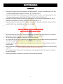
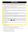
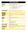
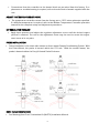
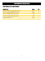
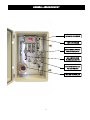
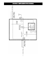
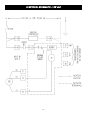
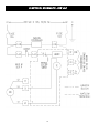
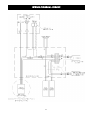
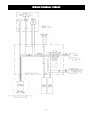
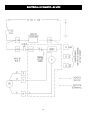
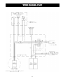
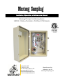
Installation, Operation, & Maintenance Manual Mustang® Sample Conditioning System MODEL: Watlow Controller—P53 Direct, P53 Remote P (304) 273-5357 F (304) 273-2531 P.O. Box 490/43 Ritmore Dr. Ravenswood, WV 26164 [email protected] www.mustangsampling.com Manufactured by Valtronics, Inc. for Mustang Sampling, LLC © 2012-2015 Mustang Sampling, LLC. All Rights Reserved. Revision: 003 Issue Date: 10/30/2015 File Name: MIOMC-P53W-CE No part of this document may be reproduced or transmitted in any form or by any means, electronic, mechanical, photocopying, recording, or otherwise, without prior written permission of Mustang Sampling, LLC. Systems and equipment are subject of Patents: US7162933, AU2005260719, CA2573120, EP05769462.2, US7882729, AU2006216870, CA2605119, CN200680013386.3, EP06735575.0. Other Patents Pending Mustang Sampling®, Mustang®, Pony®, Certiprobe®, Certicollar®, Mustang Intelligent Vaporizer Sampling System®, SoftView®, Analytically Accurate®, the Mustang Sampling® logo are all registered trademarks of Mustang Sampling, LLC.. All other trademarks and copyrights are the property of their respective owners. Mustang Sampling, LLC 304-273-5357 P.O. Box 490 Ravenswood, WV 26164 [email protected] www.mustangsampling.com TABLE OF CONTENTS PAGE Safety Warnings 2 Product Features 3 Technical Specifications 4 Installation Instructions 5 Operation Instructions 7 Maintenance Instructions 7 Recommended Spare Parts 8 General Arrangement—Fig. 1 9 Product Dimensions—120 vac—Fig. 2 10 Process & Instrumentation Diagram—Fig. 3 11 Electrical Schematic—120 vac—Fig. 4 12 Wiring Diagram—120 vac—Fig. 5 13 Electrical Schematic—208 vac—Fig. 7 14 Wiring Diagram—208 vac—Fig. 8 15 Electrical Schematic—230 vac—Fig. 10 16 Wiring Diagram—230 vac—Fig. 11 17 Electrical Schematic—24 vdc—Fig. 13 18 Wiring Diagram—24 vdc—Fig. 14 19 SAFETY WARNINGS STANDARDS Standard for Safety Electrical Equipment for Measurement, Control, and Laboratory Use; Part 1: General Requirements (ANSI/UL 61010-1, 07/12/2004, Ed. 2) Standard for Safety Electrical Equipment for Measurement, Control , and Laboratory Use; Part 1: General Requirements (CAN/CSA C22.2 No. 61010-1, 07/01/2004, Ed. 2) Standard for Safety Explosion-Proof and Dust-Ignition Proof Electrical Equipment for Use in Hazardous (Classified) Locations (ANSI/UL 1203, 1028/09, Ed. 4) Explosion-Proof Enclosures for Use in Class 1 Hazardous Locations Industrial: Industrial Products (CSA C22.2 No. 30-M1986, (G.I. No. 2, 11/1988)) Failure to abide by any of the safety warnings could result in serious injury or death. Electrical power must be “OFF” before and during installation and maintenance or personal injury may result. Follow site requirements for Safety Precaution Rules. Do not exceed any equipment pressure, or electrical ratings. To reduce the risk of fire or explosion, do not install where the marked operating temperature exceeds the ignition temperature of the hazardous atmosphere(s). Heated regulator surface temperature will approach temperature limit specified in technical specifications. Select a mounting location so that the system will not be subjected to impact or other damaging effects. The hazard location information specifying class and group listing of each system is marked on the nameplate. Properly ground all equipment to prevent static electric generation. 2 PRODUCT FEATURES The Mustang® Sample Conditioning System (MSCS) ensures optimal performance of gas analyzers by delivering a heated sample through patented technology to the analytical device. The MSCS avoids costly errors resulting from hydrocarbon dew point drop out by maintaining at least 30ºF above the expected hydrocarbon dew point. The gas sample is heated inside of the regulator before and after the pressure is reduced eliminating hydrocarbon liquid condensation caused by the Joule-Thomson effect during the pressure reduction. The MSCS conforms to the API 14.1 requirements for hydrocarbon liquid removal and heat tracing. The system extracts, conditions and transports the sample from the pipeline to the analyzer as follows: A membrane probe, housed in its own heated enclosure extracts a representative vapor phase sample from the pipeline. Liquids are removed at pipeline conditions of pressure and temperature thereby avoiding gas phase composition changes The liquid and particle free gas sample is then transported through a heated line to a sample system housed in its heated enclosure. A second separator equipped with a membrane and a liquid block mechanism provides a second and third means of protection against liquid damage to the analyzer. A heated pressure regulator (MHR, MJTHR, or MJTHRHP) downstream of the membrane separator reduces the sample pressure to the level required for the analyzer. The gas sample is heated inside of the regulator before and after the pressure is reduced. This insures that the Joule-Thomson cooling effect will not cause hydrocarbon liquid condensation during the pressure reduction. The conditioned sample is transported to the analyzer via heat traced tubing to maintain the gas temperature. Analytically Accurate® Patented technology utilizing existing power supplied by heat trace sample tubing Requires no external power or natural gas for proper operation Conforms to API 14.1 guidelines for hydrocarbon liquid removal and heat tracing Rated for Class 1, Div 1, Group D locations Optional remote mount w/ Pony® enclosure Optional integration with analyzer enclosures 3 TECHNICAL SPECIFICATIONS Classification Class 1, Div 1, Group C, D, & T3 Zone 1 Group IIB, Category 2G, IP66, Ex d IIC T3 Gb MAOP 2000 psig (138 BAR) @ 60ºF (16ºC) w/ Liquid Block upstream of MHR (Standard) 3750 psig (259 BAR) @ 60ºF (16ºC) w/ Liquid Block downstream of MHR 6000 psig (414 BAR) @ 60ºF (16ºC) Outlet Pressure Range 0-10, 2-25, 0-50, 0-100, 0-250, or 0-500 psig (0-0.69, 0-1.72, 0-3.45, 0-6.89, 0-17.24, or 0-34.47 bar) Internal Volume 5.0 cc Control Range 0-140° C Thermal Cut-Off Opens at 230° F (110° C) or 266° F (130° C) (customer specified) Connections 1/4” FNPT 3/4” FNPT Controller Watlow Model PM6C1EH-2AAAAA Regulator MHR MJTHR MJTHRHP Power 120 VAC—50/60 Hz, 375 W 208 VAC—50/60 Hz, 375 W 230 VAC—50/60 Hz, 375W 24 DC—205 W Maintains Sample Gas Standard set point at 120ºF (49ºC) Adjustable from 60-400ºF (16-204ºC) Cabinet Construction Hotpressed Glass Fiber Reinforced Polyester (GRP) or Stainless Steel Wetted Materials 316 SS/NACE Compliant; O-rings, Viton™, Other materials available—consult factory. Seat Material Teflon™ 4 INSTALLATION INSTRUCTIONS NOMENCLATURE MAOP—Maximum Allowable Operating Pressure LNG—Liquid Natural Gas BTU—British Thermal Unit TOOLS REQUIRED Standard Hand Tools Utility Knife The Mustang® Sample Conditioning System assembly can be mounted in one of several mounting configurations. Mount the Model P53 assembly in accordance with previous cautions and warnings. Perform the electrical hook up with de-energized conductors. Verify the unit that you are hooking up to matches voltage wise with the power supply that you are connecting. Damage to the unit can occur if the wrong source power is applied. A seal fitting is required for the power input connection to the controller enclosure to maintain its electrical hazard classification rating. For 120 volt single phase input power: Connect the “hot” wire to wiring terminal #1. Connect the “Neutral” wire to wiring terminal #2. Connect the earthing (ground) wire to the green screw in the bottom of the enclosure. For 208 or230 volt single phase input power: Connect one “hot” wire to wiring terminal #1. Connect the “Neutral” to wiring terminal #2. Connect the second “hot” wire to wiring terminal #3. Connect the earthing (ground) wire to the green screw in the bottom of the enclosure. For 24 vdc input power: Connect the positive wire to wiring terminal #1. Connect the negative wire to wiring terminal #2. Connect the earthing (ground) wire to the green screw in the bottom of the enclosure. A seal fitting is required between the controller enclosure and the MHR heater block. Externally connect earthing (grounding) conductors from assembly to equipment ground connections. 5 Connections from the controller to the heater block are pre-wired from the factory. If replacement or troubleshooting is required, refer to the electrical schematic supplied with the unit. ADJUST THE TEMPERATURE SET POINT. The temperature controller comes from the factory set to 120 F unless otherwise specified. If a different temperature is required, refer to the Watlow Temperature Controller operation manual for the complete setup and adjustment procedures. SET REGULATOR PRESSURE Apply input pressure and adjust the regulator adjustment screw until the desired output pressure is attained. The nut on the adjustment screw may be used to secure the adjustment screw at its set point. PROBE INSTALLATION Probe installation is the same with remote or direct mount Sample Conditioning System. With the Direct-Mount, the probe is housed within the P53 unit. With the remote mount, the probe is housed within the Pony® Heated Probe Enclosure. HEAT TRACE TERMINATION See Mustang Heat Trace Termination Kit (MHTTK) Installation Manual. 6 OPERATION INSTRUCTIONS Close the cover on the controller enclosure. Turn on the electrical supply to the controller. Allow a few minutes for the system temperature to stabilize. The pressure set point may have to be adjusted once the temperature has stabilized. Verify that sample stream supply is shut off. Verify that power to the controller is off. Install the Watlow supplied software (EZ-Zone Configurator) on a laptop or other computer. Connect to the Watlow controller using a RS-485 adapter (B&B Electronics Model 485SD9 TB or equal). Plug the adapter into the serial port. Select the serial port on the computer to be used (i.e.COM 1-COM17). The other end connects to the RS-485 terminals. On the computer, start program “EZ-Zone Configurator ”. Turn power on to the controller. Establish communication with the Watlow controller. Set its address to “1” or user preference. Set the regulator temperature set point to the recommended temperature. Initially set the regulator temperature at 120 F. For all other Watlow parameter settings, refer to the EZ-Zone User’s Manual. Slowly turn in the sample fluid flow to full open to the regulator. Adjust the regulator adjusting screw to obtain the desired output pressure. Once sample fluid is being regulated, monitor the regulator temperature to verify that the controller is maintaining the set point temperature. Verify the pressure and flow to the remote gas chromatograph or analyzer. Once the flow is correctly established to the analyzer or gas chromatograph, document the flow value. Do not adjust the flow value unless a calibration check is made on the analyzer. Do not leave power on for extended periods of time without flow through the unit. MAINTENANCE INSTRUCTIONS Once system is operational, no routine maintenance is required. Monitoring of flow and temperature values is recommended at least annually. 7 RECOMMENDED SPARE PARTS SOME PARTS ARE VOLTAGE DEPENDENT DESCRIPTION ITEM # QTY Intertec 80 Watt Self-Regulating Block Heater 10352 2 120 VAC Cartridge Heater (MHR/133HP) 6000 2 208 VAC Cartridge Heater (MHR/133HP) 11304 2 230 VAC Cartridge Heater (MHR/133HP) 11304 2 Regulator (MHR, MJTHR) 11881 1 Oven Industries Temperature Controller 5RI-1400 5332 1 8 GENERAL ARRANGEMENT INSULATED ENCLOSURE TEMP. CONTROLLER SINGLE OR MULTI-STAGE HEATED REGULATOR SELF-LIMITING BACK PLATE BLOCK HEATER MEMBRANE SEPARATOR W/ LIQUID BLOCK WATLOW CONTROLLER 9 PRODUCT DIMENSIONS 10 PROCESS & INSTRUMENTATION DIAGRAM 11 ELECTRICAL SCHEMATIC—120 VAC 12 WIRING DIAGRAM—120 VAC 13 ELECTRICAL SCHEMATIC—208 VAC 14 WIRING DIAGRAM—208VAC 15 ELECTRICAL SCHEMATIC—230 VAC 16 WIRING DIAGRAM—230VAC 17 ELECTRICAL SCHEMATIC—24 VDC 18 WIRING DIAGRAM—24 VDC 19