1
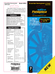
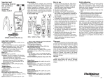
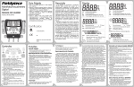
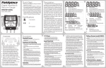
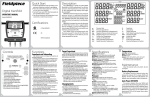
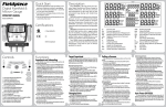
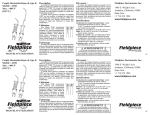
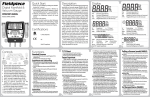
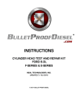
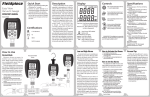
Description
Fieldpiece
Superheat and
Subcooling Meter
For A/C and
Refrigeration
with Pipe Clamp
Model: SSX34
K
SH
SC
TYPE
ATM
T2
TEMP.
UNIT
T2
AUTO-OFF
BATTERY
CHECK
ON/OFF
PRESS FOR 1 SECOND
Temp Cal
The SSX34 is a portable standalone superheat
and subcooling meter for A/C and refrigeration. The
SSX34 is designed to fit the needs of the HVACR
technician with a rugged rubber boot for durability
and magnetic hanger for easy use. Hang the magnetic hanger over a corner to minimize slip. Plug in
the pipe clamp thermocouple into the K-Type thermocouple plug. You can connect the SSX34 directly to the A/C or refrigeration system using a standard 1/4” EPA approved refrigerant hose using the
pressure port at the top of the meter. You can even
use the “T” included to charge the unit while checking superheat or subcooling, making it possible to
charge to superheat or subcooling. The SSX34 will
display superheat or subcooling for R-22, R-410A,
R-134A and R-404A.
The pipe clamp will take the temperature reading
of the refrigerant piping giving the actual refrigerant
temperature. The refrigerant hose will then sense
the refrigerant pressure. The SSX34 then uses the
actual temperature and boiling point (at the sensed
pressure) to calculate and display real-time actual
subcooling or superheat as well as display refrigerant temperature and pressure.
Operation
OPERATOR’S MANUAL
General
Operating environment: 32ºF (0°C) to 122ºF
(50°C) <75% RH
Storage environment: -4ºF (-20°C) to 140ºF
(60°F) <80% RH with battery removed from
meter.
Overrange: “OL” or “-OL” is displayed.
Auto-off power: 15 minutes
Temperature coefficient: 0.05 x (specified accuracy) per °C
Accuracy: Stated accuracy at 23°C ± 5° (73°F ±
9°F), <90%R.H.
Battery: Single standard 9-volt battery, NEDA
1604, JIS 006P, IEC 6F22.
Low battery:
symbol is displayed.
Temperature
Temperature Input: Standard K-type thermocouple connectors
Measurement range: -40 to 400ºF(-40 to 204°C)
(180°F/82°C max with supplied ATC1 pipe
clamp thermocouple)
Resolution: 0.1º
System accuracy after field calibration:
±1.0ºF @ -40 to 200ºF with field calibration
±0.5ºC @ -40 to 93ºC with field calibration
±2.0ºF @ 200 to 400ºF with field calibration
±1.0ºC @ 93 to 204ºC with field calibration
1. Connect the thermocouple pipe clamp and
refrigerant hose to the meter.
2. Calibrate if needed (see Field calibration).
3. Select °C or °F by holding down the °C or °F
Pressure
Pressure Input: Standard 1/4” male flare fitting
Measurement range:
29” HgV to 500PSIG (english)
74 cmHgV to 0 to 4000KPa (metric)
HgV indicates a vacuum measurement in either
inches (english) or cm (metric) of mercury. A
perfect vacuum would be 29.92”HgV or
76.00cmHgV. Atmospheric pressure at sea
level would be 0” HgV and 0 cmHgV.
System accuracy after field calibration:
29” HgV to 0” HgV: ±0.2” HgV
74 cmHgV to 0 cmHgV: ±0.4 cmHgV
0 to 200 Psi: ±1 Psi
0 to 1378 KPa: ±7 KPa
200 to 500 Psi: ±0.3%+1 Psi
1378 to 3447KPa: ±0.3%+7 KPa
Maximum overload pressure: 800PSIG
!
WARNINGS
!
Never take pressure readings exceeding 500Psi
(3500kPa) or serious injury or damage to the meter
may occur.
button while turning on the SSX34.
4. Hand tighten 1/4” flare to suction line or liquid
line as close to the evaporator or condenser as
possible using an EPA approved service hose
(not included).
5. Select proper pressure units (english psi or metric KPa) by pressing the UNIT button.
6. Select refrigerant (R22, R410A, R134A, or
R404A) by pressing the TYPE button and
observing the arrow at the bottom of the LCD.
7. Connect the pipe clamp to the suction (superheat) or liquid (subcooling) line at least six inches from the compressor and slide it under the
insulation for best accuracy isolating the pipe
clamp from the ambient air.
8. Select temperature to display (superheat, subcooling, or refrigerant temperature).
Temperature being displayed is designated by
the arrows along the right side of the LCD “K” is
the direct temperature from the thermocouple
(actual refrigerant temperature). “SH” is superheat and “SC” is subcooling. Pressure is constantly displayed in lower right.
9. You must wait until the system you are testing
has stabilized.
10. Once you have the superheat or subcooling
reading follow the manufacturer of the air conditioner’s specifications to properly charge or
diagnose the system.
Temperature:
To calibrate the SSX34 temperature, adjust the
pot on the front of the meter labeled “Temp-Cal”.
The best way to calibrate is to match to a known
temperature. Ice water is very close to 32ºF and is
readily available. Accuracies of one degree or better are easily obtained.
1. Stabilize a large cup of ice water. Pure, distilled
water will be the most accurate.
2. Using the Type button, scroll through temperature displayed until you reach the “K” spot,
which is the direct temperature input from the Ktype thermocouple.
3. Immerse the temp probe in ice water and let it
stabilize.
Pressure:
To calibrate the SSX34 pressure, ensure that
the SSX34 is disconnected from the pressure
source and at equilibrium with the ambient pressure. Press the ATM button and the SSX34 will
set the “zero” point of pressure to the ambient
pressure.
Battery Check Function
Service
Field Calibration
The SSX34 allows the user to check the battery
charge at any time during use, simpily by holding down the UNIT button for over one second.
The approximate percentage of battery charge
will be displayed on the main display for three
seconds before returning to its reading prior to
preforming the battery check.
Unit Fluctuations Near Zero
When the pressure/vacuum is near zero, the unit
shown on the display may fluctuate between vacuum and pressure. This is similar to a classical
gauge face as shown. Below zero is vacuum (inHg
or cmHG), above 0 is pressure (psi or kPa). There
is nothing wrong if this happens. The appropriate
units will be displayed when a pressure/vacuum
measurement is taken.
Return any defective SSX34 to Fieldpiece for
warranty service along with proof of purchase.
Contact Fieldpiece for out of warranty repair
charges.
Warranty
The product is warranted to the original purchaser against defects in material or workmanship for a
period of one (1) year from the date of purchase.
During the warranty period, Fieldpiece Instruments
will, at its option, replace or repair the defective unit.
This warranty does not apply to defects resulting
from abuse, neglect, accident, unauthorized repair,
alteration, or unreasonable use of the instrument.
Any implied warranty arising out of the sale of
Fieldpiece's products including but not limited to
implied warranties of merchantability, and fitness for
purpose, are limited to the above. Fieldpiece shall
not be liable for incidental or consequential damages.
Checking Throttle Valve (TXV, Cap. Tube, Fixed Orifice)
Subcooling
Using the
SSX34
K
SH
SC
Liquid
BATTERY
CHECK
Condenser
ow
Fl
Liquid
& Vapor
Fl
UNIT
T2
AUTO-OFF
frig e ra nt
TEMP.
Re
ATM
T2
frig e ra nt
TYPE
Re
Superheat is the difference between the actual
temperature of the refrigerant (gas) as it leaves the
evaporator and the boiling point temperature of the
refrigerant in the evaporator coil. After boiling, the
refrigerant continues to warm up. The number of
degrees it “warmed up” after boiling is called the
superheat. Under worst case conditions (low load
for fixed orifice systems), the refrigerant in the evaporator boils off near the end of the evaporator coil.
To make sure liquid doesn’t enter the compressor
under the worst case condition (low load), the refrigerator manufacturers publish charts indicating what
the superheat should be at a given indoor wet bulb
measurement and outdoor air temperature.
Measuring superheat is your best indication on a
fixed orifice system of the proper refrigerant charge
and operating conditions. If everything else is working properly and the actual superheat is too high,
add refrigerant. If it’s too low, remove refrigerant.
Subcooling is the difference between the boiling
point of the refrigerant in the condenser and the
actual temperature of the refrigerant as it leaves
the condenser. The degrees that the refrigerant
“cools down” below the boiling point is the subcooling. Under worst case scenario (low load for
TXV) the subcooling will continue to rise. If the
subcooling rises to high, liquid may be backed into
the compressor causing damage and catastrophic
failure.
On TXV systems, subcooling is the best indication of the state of charge in the refrigerant system
since these systems are designed to maintain constant superheat.
Properly charging a system ensures maximum
efficiency and longer equipment life.
The hose must have a schraeder valve depresser on one end to release the refrigerant from the
suction or liquid line. This is the same type of hose
available with most pressure gauge sets. We suggest EPA sanctioned “no leak” hoses.
Exercise caution whenever working with any
electricity and high pressure liquid or gas. Follow all
instructions provided with equipment being serviced
or installed.
ow
Measuring Actual Superheat and
Subcooling
Liquid
Liquid
& Vapor
Evaporator
ON/OFF
PRESS FOR 1 SECOND
Target Superheat and Subcooling
Temp Cal
Vapor
Heed all equipment manufacturer’s specifications, warnings and suggestions above anything
found in this manual.
To determine the target superheat (fixed orifice
system) or subcooling (charts vary dramatically
from one system to another), you need the manufacturers target superheat chart or subcooling chart.
You can use the ARH4 Fieldpiece accessory
head for both wet bulb, dew point and dry bulb
measurements.
Generic Target Superheat Charts*
Vapor
K
SH
SC
Compressor
TYPE
ATM
T2
TEMP.
UNIT
T2
T2
AUTO-OFF
Checking
Superheat
Using the
SSX34
BATTERY
CHECK
ON/OFF
PRESS FOR 1 SECOND
Temp Cal
*
These charts are an example of a
generic superheat charts for a typical fixed
orifice, split residential system. These
charts should not be used for charging. A
typical manufacturer’s recommended subcooling is 12°F (7°C). These are only examples of what the manufacturer’s may recommend. Heed all manufacturer’s indications, instructions and warnings above
those in this manual.
The indoor wet bulb measurement can be
accomplished by a Fieldpiece ARH4 or
ATWB1 and should be taken as close to the
evaporator coil inlet as possible. The outdoor dry bulb reading can be taken with an
ARH4, ATB1, ATA1 or any other Fieldpiece
air thermocouple and should be taken as
close to the condenser air inlet as possible.
v14