1
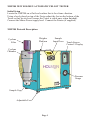
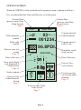
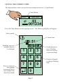
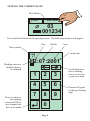
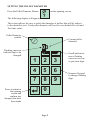
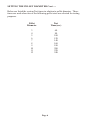
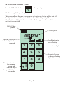
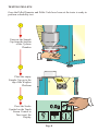
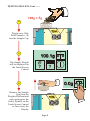
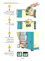
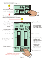
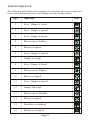
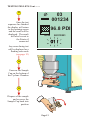
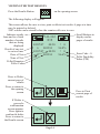
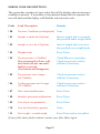
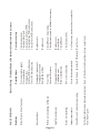
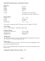
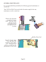
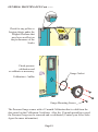
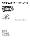
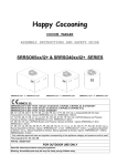
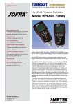
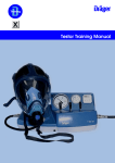
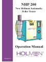
NHP 200
New Holmen Automatic
Pellet Tester
HOLM N
Operation Manual
HOLM N
®
strength
Version 1.2
in
pellet
durability
Safety
Assurance
Consistency
®
Developing, making and marketing technology
INDEX
Page
Pictorial Description
1
Opening Screen
2
Setting the Current Time
3
Setting the Current Date
4
Setting the Pellet Diameter
5
Setting the Pellet Code
6
Testing Pellets
8
Viewing Test Results
14
Error Code Description
15
Fault Finding
16
Machine Data and Specifications
17
General Maintenance
18
Declaration of Conformity
20
NHP200 NEW HOLMEN AUTOMATIC PELLET TESTER
Initial Setup
Locate the NHP200 on a flat level surface that is free from vibration.
Using a level placed on top of the Tester adjust the feet on the bottom of the
Tester so that its sits level (ensure the Tester is stable once when finished).
Connect the Mains Power supply lead. Connect the Printer (if supplied)
NHP200 Pictorial Description
Weigher
Platform
Cyclone
Filter
Sample
Input Door
Touch Screen
Control / Display
Cyclone
Chamber
HOLM N
Pressure
Gauge
Sample Cup
Adjustable Feet
Page 1
OPENING SCREEN
When the NHP200 is first switched on the opening screen is shown as follows :
It is recommended that Time and Date are set at this point.
Current Time
(press to enter Time
Setup Screen)
Page 3
Current Date
(press to enter Date
Setup Screen)
Page 4
10:51
02/07/2001
03
001234
Pellet diameter
symbol
Pellet code
symbol
Press to view test
results
Page 14
Current entered
Pellet Code
96.8PDI
08:50
Time of last test
02/07/2001
=
0.0g
Scales readout
?
?
Press to enter Pellet
Code Screen
Page 7
Page 2
Durability result
from last test
Date of last test
01 !
Error code (flash)
only displayed if
a fault occurs
Page 15
Press to enter
Pellet Diameter
Screen
Page 5
Current selected
Pellet Diameter
Press to Tare
(zero) Scales
Press to run test
on selected pellet
diameter
Page 11
SETTING THE CURRENT TIME
The time and date values are used to time stamp each test as it is performed.
Time Button
10:51
02/07/2001
03
001234
Press the Time Button on the opening screen. The following display will appear.
Time symbol
Current time
10:51
Flashing cursor to
indicate digit to
be changed
Press to return to
the opening
screen and OK to
any changes that
have been made
1
2
3
4
5
6
7
8
9
0
Page 3
Scroll buttons to
move flashing
cursor on to next
or previous digit
Numeric Keypad
to change flashing
digit
SETTING THE CURRENT DATE
Date Button
10:51
02/07/2001
03
001234
1234
Press the Date Button on the opening screen. The following display will appear.
Day
Month
Year
Date symbol
Current date
JUN
6
Flashing cursor to
indicate digit to
be changed
Press to return to
the opening
screen and OK to
any changes that
have been made
0 2:07:2001
1
2
3
4
5
6
7
8
9
0
Page 4
Scroll buttons to
move flashing
cursor on to next
or previous digit
Numeric Keypad
to change flashing
digit
SETTING THE PELLET DIAMETER
Press the Pellet Diameter Button
The following display will appear.
on the opening screen.
?
This screen allows the user to select the diameter of pellets that will be subject
to the durability test. Each pellet diameter will have its own default Pre-test and
Test time value.
Pellet Diameter
symbol
Current pellet
diameter
03
Flashing cursor to
indicate digit to be
changed
Press to return to
the opening
screen and
confirm any
changes that have
been made
1
2
3
4
5
6
7
8
9
0
Page 5
Scroll buttons to
move flashing
cursor on to next
or previous digit
Numeric Keypad
to change flashing
digit
SETTING THE PELLET DIAMETER Cont .....
Below are listed the system Test times in relation to pellet diameter. These
times are used when one of the following pellet sizes are selected for testing
purposes.
Pellet
Diameter
Test
Time (sec)
3
4
5
6
7
8
9
10
11
12
60
80
100
120
140
160
180
200
220
240
Page 6
SETTING THE PELLET CODE
Press the Pellet Code Button
on the opening screen.
?
The following display will appear.
This screen allows the user to enter up to a 6 digit code for the pellets that will
be subject to the durability test. This can be used to help with pellet
identification and if printed is connected will also appear on the result line as
each test is completed.
Pellet Code
symbol
Current pellet
code
001 234
Flashing cursor to
indicate digit to be
changed
Press to return to
the opening
screen and
confirm any
changes that have
been made
1
2
3
4
5
6
7
8
9
0
Page 7
Scroll buttons to
move flashing
cursor on to next
or previous digit
Numeric Keypad
to change flashing
digit
TESTING PELLETS
Once the Pellet Diameter and Pellet Code have been set the tester is ready to
perform a durability test.
1
Unscrew the Sample
Cup from the bottom
of the Cyclone
Chamber
2
Place the empty
Sample Cup on to the
top of the Weigher
Platform
3
=
Press the Scales
Symbol on the Touch
Screen Control to
Tare (zero) the
Display
0.0g
?
?
Page 8
TESTING PELLETS Cont ........
100g ± 5g
4
Weigh out a 100g
Pellet Sample ± 5g
into the Sample Cup
5
The Sample Weight
will be displayed on
the Touch Screen
Control
=
100.1g
?
?
=
0.0g
6
Remove the Sample
Cup from the
Weigher Platform and
once again press the
Scales Symbol on the
Touch Screen Control
to Tare (zero) the
Display
Page 9
TESTING PELLETS Cont ........
7
Open the Sample
Input Door and empty
the Sample Cup into
the Tester
8
Close the Sample
Input Door
9
Screw the Sample
Cup back into
position on the
bottom of the
Cyclone Chamber
10
Check Pellet
Diameter and Pellet
Code have been set
correctly
?
?
Page 10
TESTING PELLETS Cont ........
=
11
0.0g
Press the Start Button
on the Touch Screen
Control
?
?
The Testing Screen will now be
displayed and the sequence will begin
12
Current Time
Selected Pellet
Diameter for
Testing.
Selected Pellet
Code for Testing.
Current Date
10:51
02/07/2001
Icon will change
to indicate each
step of the testing
sequence
03
123
100
131
Total test time
Fixed scale.
Graphical display
showing pressure.
Actual pressure
0
0
070
053
Graphical display
showing time
until test finishes.
This figure is
calculated from
the totals for
Testing and
Delays entered
into the system
Actual run time
Stop button aborts the test
and returns to opening screen
Page 11
TESTING SEQUENCE
The following table defines the sequence of events once the test procedure has
been started and indicates the icons displayed on the Testing Screen
Op #
Operation
Icon
1
Sieve / Hopper is closed
2
Sieve / Hopper is opened
3
Sieve / Hopper is closed
4
Blower runs at 30mBar
5
Blower is stopped
6
Sieve / Hopper is opened
7
Sample 1st weigh
8
Sieve / Hopper is closed
9
Blower runs at 70mBar
10
Blower is stopped
11
Sieve / Hopper is opened
12
Sample 2nd weigh
13
Blower runs at 100mBar
14
Blower is stopped
15
Durability is calculated
16
Results are displayed
1
Page 12
2
=
TESTING PELLETS Cont ........
13
Once the test
sequence has finished
the display will return
to the opening screen
and the result will be
displayed. The result
will also be sent to
the Printer if
connected
03
001234
96.8 PDI
08:50
02/07/2001
01 !
Any error during test
will be displayed as a
flashing error code
(see page 12)
14
Unscrew the Sample
Cup on the bottom of
the Cyclone Chamber
15
Dispose of the sample
and re-screw the
Sample Cup back into
position
Page 13
VIEWING THE TEST RESULTS
Press the Results Button
on the opening screen.
The following display will appear.
This screen allows the user to view, print or delete test results. A page at a time
may be printed or deleted.
2047 results can be stored before the counter rolls over to zero.
Indicates results
from and to of total
number of results
that are being
displayed
Result of one test
is on two lines
Date of Test
Time of Test
Pellet Diameter
Pellet Code
Scroll Buttons to
display earlier
pages of results
311-312
/312
02/07/07
08:50
6
001234
02/07/07
08:50
6
001234
! 0
96.8%
! 0
96.6%
Error Code : 0
Pellet Durability
Index (PDI)
Press to Delete
current page of
results
Press to return to
the opening
screen
If Delete is
pressed a
confirmation
screen appears.
Press again to
confirm & delete
Press to return to
the Results screen
X
X
Page 14
Press to Print
current page of
results
ERROR CODE DESCRIPTIONS
The system has a number of error codes that will be display when an incorrect
condition is present. If a problem is encountered during the test sequence the
test will abort and the display will flash the relevant error code.
Remedy
Code
Fault Description
! 00
No error Condition (not displayed) None
! 01
Sample is under the 80g limit
Insert a sample that is not under
the specified under weight limits.
! 02
Sample is over the 120g limit
Insert a sample that is not over
the specified over weight limits.
! 03
Weigher fault
Reset Tester.
! 04
No air pressure (<10mBar)
If no pressure the Tester will
abort and will not run until
fault is corrected
(Test button will disappear).
Check Blower is operating.
Check air pressures and recalibrate if necessary.
! 05
Test pressure out of range
(66-74mBar)
Check air pressures and recalibrate if necessary.
! 06
Cooling pressure out of range
(26-34mBar)
Check air pressures and recalibrate if necessary.
! 07
Drive board malfunction
Reset Tester.
! 08
Interface processor malfunction
Reset Tester.
! 09
Loss of pre-set parameters
Reset Tester.
! 10
Last test aborted by operator
None.
! 11
First weigh < second weigh
Reset Tester and re-test pellets.
If any of the above faults continue contact your After Sales Agent.
Page 15
Page 16
Power not connected.
Tester has been disturbed.
Touch Screen / Interface PCB locked. Reset Tester.
Scales not operating.
Inconsistent results.
Touch Screen Control not operating.
For further information, replacement parts or if any of the above faults continue, please contact your
After Sales Agent.
Let Tester carry out several tests to stabilise.
Check connections.
Replace seals.
Re-calibrate
Check Blower.
Damaged plenum seals.
Calibration error.
Blower malfunction.
Check Blower is operating.
Check pressures and re-calibrate if necessary.
Replace seal.
Replace seals.
Insufficient pressure.
Damaged window seals.
Damaged seal around
Sample Input Door.
Excessive dust.
Check connections.
Check on/off switch.
Check fuses on Driver PCB.
Check Interface PCB connections.
Check Driver PCB connections.
No air flow.
Incorrect Pressures.
Not connected to supply.
Not switched on.
Damaged fuse.
Interface PCB malfunction.
Driver PCB malfunction.
Pellet Tester will not function.
Corrective Action
Pellets not circulating in Hopper.
Possible Cause
Refer to Setup / Technical Manual for further information where necessary
Problem
FAULT FINDING
NHP200 MACHINE DATA & SPECIFICATION
Pellet Test
Depth
Width
Height
Weight
Colour
Power Supply
Voltage
Cycles
Power
Fuse Rating
400 mm
720 mm
700 mm
50 kg
Cream RAL 1015 Semi Gloss
Green/Blue RAL 5021 Semi Gloss
110v .... 230v
50 / 60 Hz
1350W
13A .... 5.6A
All electrics comply with the EC Directive on Low Voltage 73/23/EEC
Pellet Range
3mm < 12mm Diameter - Maximum 30mm long
Pressure Setting
Cooling Cycle (Pre-Test)
Testing Cycle
Purging Cycle
VR2 30 mBar
VR3 70 mBar
100mBar
Temperature
The NHP200 should be operated within an ambient temperature of between
18º C and 28º C to ensure consistent results.
Noise Levels
83 db without pellets at one metre. Noise levels will vary depending on the
type and size of pellet under test.
Note : It is recommended that ear protection is worn when working near the
Pellet Tester.
Maximum Weigher Platform Loading - 500g
Page 17
GENERAL MAINTENANCE
It is recommended that periodically the following general maintenance is
carried out.
Turn 'OFF' the Pellet Tester and isolate the mains supply before any
maintenance work is carried out.
Remove the clip from
around the Cyclone
Filter. Wash the Filter
and leave to dry
thoroughly before
securing back onto
Cyclone
Rubber Door Seal
Open the Sample Input
Door and check the
condition of the rubber
seal. A damaged seal
will have an affect on the
performance of the Tester
Page 18
GENERAL MAINTENANCE Cont ........
Check for any pellets or
foreign objects under the
Weigher Platform that
may have an affect on
the performance of the
Scales
Check pressure
calibration and
re-calibrate as necessary.
Gauge Gasket
Calibration ± 3mBar
Gauge Mounting Screws
The Pressure Gauge comes with a 12 month Calibration that is valid from the
date stated on the Calibration Certificate. After the 12 month period has ceased
the Pressure Gauge can be removed and re-calibrated (Contact your After Sales
Agent for more information).
Page 19
DECLARATION OF CONFORMITY
Equipment Description
NHP 200 - New Holmen
Automatic Pellet Tester
Manufacturer
TekPro Limited
Willow Park
North Walsham
Norfolk
NR28 0BD
United Kingdom
United Kingdom regulations
The Supply of Machinery (Safety) Regulations 1992 (S.I. 1992/3073) as amended.
The Electrical Equipment (Safety) Regulations 1994 (S.I. 1994/3260) as amended.
The Electromagnetic Compatibility Regulations 1992 (S.I. 1992/2372) as amended.
European Directives
Council Directive 98/37/EC for Machinery as amended.
Council Directive 73/23/EEC for Low Voltage Directive as amended.
Council Directive 89/336/EEC for Electromagnetic Compatibility as amended.
Declaration
We hereby declare that the New Holmen Automatic Pellet
Tester complies with the Council Directives stated above.
Date
20th February 2007
Signed
.......................................
Sales and After Sales Contact Information
TekPro Limited
Willow Park
North Walsham
Norfolk
NR28 0BD
United Kingdom
Tel : +44 (0) 1692 403403
Fax : +44 (0) 1692 404955
Email : [email protected]
Web : http://www.tekpro.com
http://www.holmenfeed.com
http://www.holmenwood.com
Manufactured and Sold under license
from Borregaard UK Ltd by TekPro Limited
Page 20
D. Catchpole
Technical Director
®
Developing, making and marketing technology
TekPro Ltd
Willow Park
North Walsham
Norfolk
NR28 0BD UK
Tel +44 (0) 1692 403403
Fax + 44 (0) 1692 404955
Email [email protected]
Web www.tekpro.com
®
accurate bulk sampling
HOLM N
®
strength in pellet durability
INS CTOMAT®
insect detection you can count on
innovation
simplicity
focus
Printed in United Kingdom by TekPro Limited