1
®
COMMAND PRO
USER’S MANUAL
!
"#
+,-!,.,
$%$$&'($%
$)*&
$)$%
$)'
-#
/
(
)%
0(0
(
$1$1$%&$
&
'0
1916 W. Mission Road, Escondido, CA 92029-1114 • Ph: 800-328-5570 • Fax: 760-737-7810
ADDENDUM – ADDITIONAL WARNINGS
IMPORTANT SAFETY NOTICE
WARNING:
THE USE OF UNAPPROVED COMPONENTS OR ACCESSORIES IN
THE SYSTEMS SOLD BY CATTRON GROUP INTERNATIONAL AND
ITS SUBSIDIARIES IS STRICTLY PROHIBITED. UNAPPROVED
COMPONENTS ARE DEFINED AS ANY COMPONENT NOT
INSPECTED AND SOLD BY CATTRON. THIS ALSO INCLUDES ANY
COMPONENT MODIFIED FROM ITS INTENDED USE AND/OR ANY
COMPONENT EXHIBITING OBSERVABLE DAMAGE OR DEFECT.
USE OF NON-CONFORMING PARTS, ASSEMBLIES AND
ACCESSORIES MAY LEAD TO INJURY OR DEATH.
WARNING:
THE REMOTE CONTROL SYSTEM YOU HAVE PURCHASED IS
DESIGNED TO STOP IN A SAFE MODE UNDER A VARIETY OF
CONDITIONS. SOME EXAMPLES OF THESE CONDITIONS ARE:
EXCESSIVE RADIO SIGNAL INTERFERENCE, LOSS OF BATTERY
OR ELECTRICAL POWER, FAILURE OF CERTAIN COMPONENTS
AND OPERATION BEYOND SIGNAL RANGE AND OTHERS.
ALTHOUGH CATTRON GROUP INTERNATIONAL AND ITS
SUBSIDIARIES DOES NOT SPECIFY THE POSITION OF THE
OPERATOR WHEN CONTROLLING THE EQUIPMENT WE ARE
AWARE THAT SOME USERS ARE INSTRUCTED AND TRAINED BY
THEIR EMPLOYER TO RIDE THE EQUIPMENT IN A SAFE MANNER.
IT IS IMPERATIVE THAT YOU ARE PREPARED FOR AN
UNPLANNED STOP OF THE EQUIPMENT AT ANY TIME AND DO
NOT PLACE YOURSELF OR OTHERS IN A POSITION WHERE THIS
SITUATION MAY CAUSE YOU TO FALL FROM THE EQUIPMENT.
FAILURE TO USE CAUTION MAY LEAD TO INJURY OR DEATH.
END
232
REMTRON, INC.
COMMAND PRO® RECEIVERS
FCC COMPLIANCE STATEMENT
COMMAND PRO® series receivers have been tested and found to comply with in the limits
for a Class B digital device, pursuant to Part 15 of the FCC Rules. These limits are
designed to provide reasonable protection against harmful interference in a residential
installation.
This equipment generates, uses, and can radiate radio-frequency energy, and if not
installed and used in accordance with the user manual, may cause harmful interference to
radio communications. However, there is no guarantee that harmful interference will not
occur in a particular installation.
If this equipment does cause harmful interference to radio or television reception, which
can be determined by switching this equipment on and off, the user is encouraged to try to
correct the interference by one or more of the following measures:
•
Re-orient or relocate the receiving antenna that is connected to the device that is
receiving the interference.
•
Increase the separation between our equipment and the equipment that is receiving
the interference.
•
Consult our factory or one of our Service Representatives for additional help.
Responsible Party:
Remtron Inc.
1916 W. Mission Rd.
Escondido, CA 92029
Ph: 800 328-5570
760 737-7800
2
32
This page intentionally left blank
2
32
Table of Contents
45
657245
8( $$&'( 4565 5 !"'#9 :;(' $)$%$$1$) /:$"$ %
$$%:$ %
$&'<
$&$$%:$( =
&$ =
$$% >
$$%!" >
$(%$
$$($"$
:(/' 4565 ($ /$)";( $/$ 1/$ $$#) &(((** 8!$#) $$ ) 456
4
?52@
55!
)
"' >
$$ (*") >
$$ (*")$"$ >
($ (*") $ (*") $&$ $ (*")$"$ $)" $*$ $"$))" $'$% $$8$/ 1 (*") ($ 1 ) 1$ %
:($ %
1$8$/ <
2
32
456"A
,5
5
455A
$ 1$% ($ &#$$' 1 7B-
4,45 $&$ 7B@-
4
.
4,45
List of Illustrations
,!2
5
,!2
5
4
.
,!2
4
.
45245 ,!2
4
4
,!2
4
.
C
D
,!2
/45
457@
,5
4
.
/
,!2
07
7
"@4E
5.
7 ,!2
),2
545 /
+
2
32
SAFETY RULES
!
"#
,#!
-1$-!%
,23432332F35
!
--!%
•
!527
4
.
4
%($&'&"'G"1
$(*&'%$")(%
•
5.7
,
A425,,"4&$$;(%G"$%(*
%%&!1$%$$1$
•
2
5 "!/&$'%!$$($%$$1$&
$"'
•
7555
"$$$($*%$$)%*'"$H
&<I:
•
755!.@5
"&&"$$$()"*
"%"()")H("$9)1*$
&,%
',-6
•
E
2
4
A4
@
,5
5 !'$1$"
'($&%
•
"45,,
4
.
5"
@
,5
"5E!54
A!$'
%"'!*&%)$'$$1
$%$$&"$"
$,
•
E
7A&!$";(%)%G%$'%'"(
•
E
CD4
7$$$$%&&
IMPORTANT NOTE: Throughout this manual, other safety rules appear under the following heading.
!
"#
,23432332F35
+
2
32
CONSIGNES DE SÉCURITÉ
+,-!,.,
-#
893238:3;3
!
--!%
•
4457
@5J
K
8(;('L&(
0(0G*M%(0(%N%$%0O$$
•
,522
2 27
P42P/%$1$(H%<%(
%&G%0$%$&%<01($"$%
•
2
, 5 P'&%0(1((0(11;((
%0$$)$%%$$"
•
77
75427'0$((0(O
<I:==I$>(1%$)<$$
•
7
7552K7
,5
.@5
/<H)0%$$O%1*$(%((
0%($%(0%1
?$1!-?
•
32
Q2
4
7P!!P
.7
,
,545
$&$&'L%00)(%$)O;($
(N&$(0(0
•
P4
25
5.73
,,
4
27
.2B
24
&%01$$"$%%$
$"G(@(%0*$"'L%00)(%$)$1$%%<&&(%
$1$(H%<
,
-,-!,
•
!7
2
40"0%$<$$G<H0O%<$(((
$(;(%
•
!7
5 ($%$%%<$
H%/%)($(%*(
0(
893238:3;3
+
2
32
Section 1 — Introduction
Purpose
This manual provides information on the safe installation and operation of the
Remtron wireless control systems. Information is also included on the
maintenance and repair of the systems.
Scope
Information is included on all Remtron transmitters and receivers. See
the detailed information contained in each section of this manual for your particular
equipment.
The transmitters covered in this manual contain enhanced features that expand the
types of applications for the systems.
Many new features have been added, but most changes are transparent to the user. If
you are already familiar with Remtron transmitters, you are encouraged to read the
section on operating the transmitters, where you will find information about the latest
changes in operation.
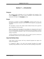
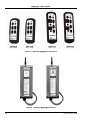
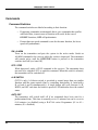
To help you identify your system, Figures 1 and 2 on page 2 provide a reference for
the transmitters and the receivers covered in this manual.
Important Safety Rules
Using wireless control systems with heavy industrial equipment can improve the
safety of the equipment.
It is important to adhere to the safety rules presented throughout this manual,
especially during installation, in order to achieve the safest operating system possible.
2
32
'()-*
'()+
2
32
This page intentionally left blank
2
32
Section 2 — Operations
Remtron Wireless Control Systems are designed for control of industrial
machinery. These rugged controls are built to survive the wear and tear of life in factories,
mills, and foundries.
These systems comply with requirements for operation under Part 15 of the FCC Rules and
Regulations. This means that neither the operator nor the company need apply or register for
a license to operate this equipment.
The basic system consists of a transmitter and a receiver. The transmitter sends commands to
the receiver by means of radio waves in the 900 MHz band. Receivers operate at 120 VAC
50/60 Hz power.
How the System Works
Frequency
Remtron equipment operates in the 902 to 928 Megahertz (MHz)
frequency band. A wavelength at our frequency is 12.9 inches.
Like light, 900 MHz radio signals will pass through glass and plastics, and will
reflect off of walls, buildings, and metal structures. Unlike light, 900 MHz radio
signals will penetrate all plastics, including those that you cannot see through,
thin-gauge steel, dry wood, dry concrete, plasterboard, fog, and rain.
However, trees, earth, water, people, aluminum, copper, and some window tints
will not readily pass our signals.
Range and Antenna Coverage
Antennas convert radio signals into radio waves and convert radio waves back
into radio signals. They can send and receive in all directions or in a single
direction, depending on their design.
An omni-directional antenna is like a light bulb, and a directional antenna is like a
flashlight. Metal objects reflect radio waves, just as a mirror next to a light bulb
will reflect light. Metal objects near an antenna alter the intended pattern of an
antenna by either shading or reflecting signals.
Our standard antennas are omni-directional; they ‘see’ equally well in all
directions. We have other antennas that will ‘see’ further in one direction for
special applications.
2
32
License-Free Channels
The 902 to 928 MHz spectrum is set aside by the FCC as an ISM Band
(Industrial, Scientific, and Medical), and this spectrum accommodates many
license-free users. We have the ability to change frequencies in this band, and we
have 81 different channels that we can assign to our transmitters and receivers.
The actual frequency is coded into the receiver and transmitter at the factory, but
it can be changed to one of the other 80 channels in the field.
Other devices in this band include wireless phones, computer data links, and
inventory equipment. As a condition of using this band, we must accept and
handle interference from other users.
The 900 MHz band has worked well for most users, and not being burdened with
licensing regulations is desirable. The FCC has allowed 50,000 microvolts per
meter field strength on this band, which is 250 times higher than other unlicensed
frequencies below this band. This allows our systems to operate very reliably in
the presence of other signals.
Command Format
We use packet-mode, Frequency Modulation (FM) to carry commands in a packet
form from our transmitter to our receiver.
To reduce battery drain, our transmitter transmits for a hundredth of a second,
which is long enough to send one packet to our receiver at a repetition rate of 16
or four times per second.
The rate varies: 16 times per second for three times when sending a command and
four times per second when there is no change in commands and the transmitter is
still on. Any time a lever or switch is activated, we send all control settings three
times at the 16-per-second rate and then return to the slower rate of four times per
second.
Our receiver uses the slower rate for maintaining transmitter timing and provides
for a maintained link where one is used. The only exception to this is the ‘STOP’
switch, which transmits at 16 times per second as long as it is depressed. In
addition to lever and switch positions, each packet contains a unique address and
CRC check sum (described in the next paragraph).
2
32
Safety
Safety and preventing loss of control are very important issues at Remtron. We
use a unique identification (ID) code for each user. There are provisions in our
system for 65,535 individual codes.
Each transmission includes a CRC check sum, which is a polynomial created by
factoring all of the previous bits transmitted. Once our receiver receives a valid
start command from our transmitter, our receiver tracks the time of the transmitter
and ignores all other transmissions that do not fall within the expected time frame
of our transmitter.
Maintained link systems must receive at least one valid transmission each second
in order to allow the remote-controlled equipment to function. Our receiver
provides a loss-of-signal control output that safely shuts down the equipment if a
loss of signal occurs.
Our receiver will not allow restart of equipment under its control after a loss of
signal until a valid system start command is received from our transmitter. This
prevents an unintended start-up from occurring if the transmitter returns within
range of our receiver and is still operating.
Our transmitters also check the position of all controls upon start-up. Our
transmitter will not issue a start command if any of the controls are pressed at the
time the start command is invoked.
/
2
32
Transmitter Operation and Features
!
'$"'('($&$$
!"$%%$&'($
&$$!"$%%$G$'(
(1*&$)("$%
'
"#
+,-!,.,
-#
$&$&'L$1$%*
$M&%<()($
00)(%$)$$(1($1$%&$
($1%$"$00)(%$)G
&<$(
!.&%-
-#
"'$)'G$%"%
"&:: &8*(8)$%"%)"
*(%!$&(
!.&%-
-#
/*(%<$N%<()= &8>('L
*(5,,
5 ('$
(($N(&(
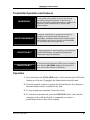
Operation
1. Press and release the ON/ALARM button. Verify that the status LED starts
flashing at a low rate. If equipped, the Alarm function should sound.
2. Press the required switches to operate the desired function. Note that more
than one function can be controlled at any time.
3. To stop sending any command, release the switch.
4. To switch the transmitter off, press the OFF/STOP button. (Note that the
transmitter will switch itself off if no commands are sent for a
predetermined time if Auto Off is enabled).
0
2
32
Commands
Command Switches
The command switches are labeled according to their function.
•
If opposing commands are attempted, that is, two commands that conflict
with each other, in most cases no function will result. In the case of
ON/OFF functions, OFF will predominate.
•
If more than one speed command is sent for the same function, the lower
speed will predominate.
ON / ALARM
Turns on the transmitter and puts the system in the active mode. Sends an
ALARM command to the receiver while the switch is depressed. The transmitter
will remain active until the OFF/STOP button is pressed or the transmitter
switches itself off (see Auto Off).
OFF / STOP
While depressed, sends a STOP command to the receiver. The transmitter does
not need to be switched ‘ON’ to send this command. When this switch is released,
the transmitter will be switched off.
A–B SWITCH
(25T15A only) A Selector switch is provided to control more than one similar
function with the same controls (that is, controlling hoist/trolley A, hoist/trolley
B, or both A and B simultaneously). A single button will cycle between A, B,
BOTH, and OFF each time the button is pressed. LED indicators show the control
status.
AUTO OFF
The transmitter will switch itself off if no commands have been sent for a
predetermined time. This time is normally set to 15 minutes but can be re-set to
0–60 minutes (or disabled) using a RAC16A series Programmer (01 to 60 =
minutes, 00 = disabled).
)
2
32
Status Indicators
Status LED
The status LED provides an indication of the transmitter operation. When the
transmitter is operating normally, the LED indicator will emit short flashes at a
low rate when no commands are activated and at a higher rate when a command
is activated. Some transmitters use a red LED only. Others use a multicolored
LED that flashes GREEN when no problems are present and changes to RED
under low battery conditions or when other problems are encountered. See Status
Chart below.
Transmitter Status Chart
782
/'&&
/'&$"$!$
:423
$&&R!"$&
*$$%$%R$*$
$&$(R$&1
$$)$$%
/'&$"$")"$
$$%!"%
/'&$"%(
=S<'>
*$))!*$"(%*
"$)%$"H1('
/'&$"&&$$
!$=T%
$%T%&&>
*$))!*$"(%*
"$)%$"H1('
/'$
"$!"!$$1$%$""
(('=/')" $!$!"%$)$&$(
&9)"'>
(%"$;(&$'1(
"!"$%!"$)
!""$
/'!)"!"
&&::*(
("%
$*$&"%"
*G"$(*$%
Function Select LEDs
Two LEDs are used on 25T15A transmitters to indicate which control functions
are active (such as hoist/trolley A, hoist/trolley B) and are intended to be used
with pilot relays. When both are lit, both controls are active. When both LEDs
are unlit, neither control is active.
2
32
Section 3 — Installation
General
Check all of the components to confirm that they are the components you ordered for
your system and that they are in good condition. If any components are missing, or if
any are not in good condition, contact Remtron.
!
'// ,$ &A:$(&!"
: -,/$(($@('
*&$)"$$G("$"
$!"$*%%$%"$$
$$*$&'$($&!%
"#
+,-!,.,
/%$&('.$, .(
-# $(%*(0(1$%0%O
<$$G<$(;(*$001$(($
)(";(()%
0(0000
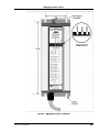
Figure 5 on page 14 shows a typical receiver. See this figure for mounting
dimensions and antenna connector location.
Locating the equipment
Antenna Location
The antenna is one of the most important components of a radio receiving system.
Proper placement of the receiver antenna will ensure reliable operation under the
most severe conditions. A direct ‘line-of-sight’ path between the transmitter and
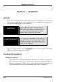
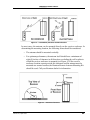
receiver antenna provides the best performance (see Figure 3 on page 10).
2
32
'()-*+$)*
In most cases, the antenna can be mounted directly on the receiver enclosure. In
determining the mounting location, the following items should be considered:
•
The antenna should be mounted vertically.
•
For optimum performance, the antenna itself should have a minimum of
eight (8) inches of clearance in all directions, excluding the wall or plate to
which the receiver enclosure is mounted (see Figure 4). If the receiver
enclosure location cannot provide this clearance and the antenna must be
mounted at a remote location, the Remtron Remote Antenna Mounting Kit
should be used. Call your Remtron dealer for information.
'()*$**
2
32
Receiver Location
To ensure safe and reliable system operation, the following items must be
considered when selecting a location for mounting the receiver:
•
Install the receiver in an environment where the ambient temperature
during operation does not drop below -20º F (-28º C) or rise above +160º F
(+71º C).
•
To ensure that the receiver enclosure is electrically at earth ground, connect
the green wire in the interface cable to earth ground.
•
Mount the receiver enclosure securely using appropriate locking-type
hardware.
Installation Wiring
.!,,
!
*&$)"$$G("$"
$!"$*%%$%"$$
$$*$&'$($&!%
"#
"#,#
1$%0%O<$$G<$(;(
*$001$(($)(";(
()%0(0000
#
$;($!"")"
1$)(;(;(
%$$'
+,-!,.,
/$HO%0;((O%$
(O%0;(010(O%
&0%($0<$$
%<&$O$
$1-!%
-#
2
32
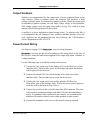
Output Snubbers
Snubbers are recommended for the suppression of noise generated from arcing
relay contacts. When a contactor opens, the contactor coil produces a large
voltage potential, much like automotive ignition systems. When the points open
on automotive ignition systems, the coil sends a large voltage to the distributor.
This voltage jumps across the spark plug (called arcing). The result is a large
amount of noise being generated in the system.
A snubber is a device designed to reduce arcing (noise). To increase relay life, it
is recommended that all contactors have snubbers installed directly across the
coils. Snubbers can be purchased directly from Remtron, Inc. Call Remtron’s
Service Department at 800-328-5570.
Power/Control Wiring
See Figure 6 on page 15 for receiver wiring diagrams.
receivers are pre-wired according to the wiring label on the face of
the receiver. Limit the load current applied to the output relay bank ‘common’ to
5 amps maximum.
Use the following steps to install the wiring to the receiver.
1. Connect the ‘hot’ input wire for the bridge (X1A) to the black wire of the
interface cable. This provides power for the bridge and alarm functions as
well as power for the receiver.
2. Connect the neutral (X2) wire for the bridge to the white wire of the
interface cable. This provides power return for the receiver.
3. Connect the ‘hot’ input wire for the trolley and hoist (X1B) to the
black/white wire of the interface cable. If only one power source (phase) is
used, this will be the same as Step 1 above.
4. Connect the red wire to the coil of the main line (ML) contactor. This wire
will provide a continuous voltage to the ML Coil when the transmitter is
active. If a pendant is also connected to the controls, we recommend the
addition of a transfer switch to select either pendant or radio control.
5. Connect the remainder of the wires to the control relays as required.
2
32
%-,
"$%$%1$&$
"!"#"$)
"$%$%!"G
"!!&"%%=(# $%
'# >%*@%)"$%!%
"$$$&"%%
Review the steps above to ensure the accuracy of the wiring before applying
power to the installation.
Installation Testing
Before putting the system into service, the following testing procedure must be
performed:
1. Apply power to the receiver.
2. Verify that PWR indicator turns on. See Figure 5 on page 14.
3. Turn on the transmitter.
4. Verify that the SIGNAL indicator flashes.
5. Verify that voltage is present at the receiver output to the Main Line
Contactor (MLC).
6. Verify that no voltage is present at any of the relay output terminals that
are used for your application.
7. Recheck the system wiring if voltage is present at any output terminal that
is used.
2
32
'()/+0//1
2
32
'()2$*3*45+
/
2
32
This page intentionally left blank
0
2
32
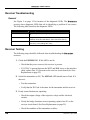
Section 4 — Maintenance & Troubleshooting
Monthly Inspection
It is recommended that the following tasks are performed once a month:
•
Inspect the transmitter for damage to the keypad and case.
•
Inspect all electrical and antenna connections to ensure they are clean and
tight.
Installation Troubleshooting
If the system fails to operate at the time of installation, or after a system
component has been repaired, try to remedy the problem by using the following
troubleshooting chart. If this does not solve the problem, proceed to the
transmitter and receiver troubleshooting charts or call Remtron Service.
Installation Troubleshooting Chart
:
1!
%"
$
:423
#)$
%
85
$9($"
&"1)$"
$
$* " $ (*")
$"$$)
'"$"
$)
&(
$
)
1*
1 (*")$)
$$
1"$$=$
/$$)>
$$*
"%
$"9$*$%"
$$
8)$)
$"9"&)($"
$)$';(
$$1
2
32
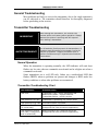
General Troubleshooting
Most problems are likely to occur in the transmitter, due to the rough treatment it
can be subjected to. The transmitter should therefore be thoroughly diagnosed
before proceeding to the receiver.
Transmitter Troubleshooting
!
#")"$G"1$
*$1$%$('$!$'
$("'!9)$%!%
!")$$
"#
+,-!,.,
-#
/%<$%&%($(G
0((N$101;($
$"%('L (@(%0;(
'L&;(<0%$$(H$%(
$(
Normal Operation
When the transmitter is operating normally, the LED indicator will emit short
flashes at a low rate when no commands are activated and at a higher rate when a
command is activated.
Some transmitters use a red LED only. Others use a multicolored LED that
flashes GREEN when no problems are present and changes to RED under low
battery conditions or when other problems are encountered.
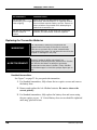
Transmitter Troubleshooting Chart
782
/'&&
/'&$"$!$
:423
$&&R!"$&
*$$%$%R$*$
$&$(R$&1
$$)$$%
/'&$"$")"$
$$%!"%
/'&$"%(
=S<'>
*$))!*$"(%*
"$)%$"H1('
/'&$"&&$$
!$=T%
$%T%&&>
*$))!*$"(%*
"$)%$"H1('
2
32
782
:423
/'$
"$!"!$$1$%$""
(('=/')" $!$!"%$)$&$(
&9)"'>
(%"$;(&$'1(
"!"$%!"$)
!""$
/'!)"!"
&&::*(
("%
$*$&"%"
*G"$(*$%
Replacing the Transmitter Batteries
!
"$<$
H%!""*$9&"$1%
$9$1%"$$
&)"$'$!"(*
$%%$$)%$'!$'
"#
+,-!,.,
-#
/;(<%%(*M10G
$0;(O%0(18%
%<01%$$$0(($(
$$%$*M.1%<0$&
(%<%$)(%;(;(&$U;(
Handheld transmitters
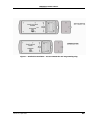
See Figure 7 on page 23 for your particular transmitter.
1. For Standard transmitters, fully release the two captive screws and remove
the battery door.
2. Remove and replace the AA Alkaline batteries. Be sure to observe the
correct polarity.
3. For Standard transmitters, fully replace the battery door and secure using
the two captive screws. ‘A’ Series Battery door screws should be tightened
until snug, plus half a turn.
2
32
Changing the Transmitter ID Code
Changing the ID Code requires use of a Remtron RAC16A series programmer.
See Figure 7 on page 23.
1. Confirm that the batteries are in good condition (refer to the Transmitter
Troubleshooting Chart on page 18).
2. Remove the battery door and batteries before removing the back of the
transmitter.
3. Attach the programming plug to the 4-pin connector on the circuit board.
Verify that the ID Code is displayed.
4. Enter the new ID Code and press the PRG key. The RAC16A display
should read ‘SUCCESS’.
5. Replace the battery door and batteries after replacing the back panel. ‘A’
Series captive screws should be tightened until snug, plus half a turn.
See the RAC16A series User’s Manual for more detailed instructions.
2
32
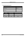
Transmitter Spare Parts List
2V
$ $=>
Use Model No./Serial Number
"(%$
<>
$$!G<%>8"G$
%=
$$$%*$'%!G$1GS<
$
%
$ $/$*
Use Model No./Serial Number
8
2
42 + 3
% >
<
<
% <
<
% <
<%
% %
<
<%
2
32
'()6*33**7**3&(*(&)(
2
32
Receiver Troubleshooting
General
See Figure 5 on page 15 for location of the diagnostic LEDs. The receivers have diagnostic LEDs that aid in identifying a problem if one occurs.
The following table describes the diagnostic LEDs.
7
29
8#
1$)1$)!""/'
(/
)$*)1%"$$""%%<
$%%!""/'&$"=/$"(%*$1>
&, 8, &$%(($)W%!""
/'G(%)/$$'
Receiver Testing
The following steps should be followed when troubleshooting the receivers.
1. Check the POWER LED. If this LED is not lit:
•
Check that the power source to the receiver is present.
•
If 115VAC is present between the WHT and BLK wires on the interface
cable, replace fuse F3 if present on the receiver circuit board (See Fuse
Replacement on page 25).
2. Switch the transmitter to ON. The SIGNAL LED should start to flash. If it
does not:
•
Test the transmitter.
•
Verify that the ID Code is the same for the transmitter and the receiver.
3. If only some functions are operating:
•
Check the output voltage of the respective relays and the electrical
circuits.
•
If only the bridge functions are not operating, replace fuse F1 on the
receiver circuit board. (See Fuse Replacement on page 25).
•
Check the condition of the transmitter switches.
2
32
4. If you are experiencing intermittent operation:
•
Check all connections.
•
Check the antenna connections.
•
Install noise-suppression devices across the coils of all contactors.
5. If the operating range is short:
•
Check all antenna connections and transmitter operation.
•
On new installations, verify that the receiver antenna is placed properly.
If necessary, use an antenna mounting kit to relocate the antenna to a
more favorable location.
Receiver Repairs
receivers have been designed for the utmost reliability. Other than
two fuses to protect the basic power circuits, there are no serviceable items in the
receiver.
Fuse Replacement
See Figure 8 on page 25.
1. Ensure power is switched OFF to all receiver power inputs.
2. Remove the mounting bolts from the end of the receiver by the interface
cable.
3. Remove the four screws on the end of the receiver near the interface cable.
4. Gently pull the end cap and receiver board out of the case about 1 inch so
that the fuses on the bottom edge of the circuit board are exposed.
5. Using a voltmeter, verify that no power is present on either of the fuses.
6. Replace the appropriate fuse with a GMC 125V 10A M/D or equivalent
fuse 125VAC for F1 or F2. For F3 use 250v/250mA
7. Reposition the end cap and insert and tighten the four screws snugly.
8. Replace the mounting bolts to the end of the receiver by the interface cable.
2
32
'()8')*
Receiver Spare Parts List
2V
1$*'=>
,%
1$
>%<
(**
<%
%9$
$$**'!*$%$
( $
$()7!$)*$9G<
$H$*$%
<>
$()7!$)*$9G><
$H$*$%
<>
%%9&(
%>
%9&(
%>>
$&!"
%
/
2
32
This page intentionally left blank
0
2
32
Section 5 — Warranty Statement for Remote Control Systems
Transmitters
Transmitters are unconditionally warranted against malfunction or breakage for a period
of one year and thirty days from the date of the original invoice except in the event of
total destruction of the internal circuit board(s), immersion in water or fluid, or
destruction by fire. Handheld transmitters used in corrosive environments must be
protected by use of the Remtron clear plastic sealed pouch.
Receivers and Accessories
Receivers and accessories, in normal and customary use, are conditionally warranted
against malfunction or breakage for a period of one year and thirty days from the date of
the original invoice. The warranty does not cover: (a) defects or damage resulting from
use of the product in other than its normal and customary manner; (b) defects or damage
from misuse, accident, or neglect; (c) defects from improper testing, operation,
maintenance, installation, alteration, modification, or adjustment; (d) damage from
unauthorized repair or alterations; or (e) damage from water or corrosive materials
beyond the specification of the case or enclosure.
General Terms of Warranty
Remtron will repair or replace the defective unit, solely at our option in the event of
defect or failure to perform as specified, provided the product is returned in accordance
with the terms of this warranty. Replacement parts are covered for the balance of the
original warranty. All costs of shipping to Remtron shall be borne by the purchaser. The
warranty covers the cost of return one-way shipping and handling of the product. The
return shipment to the customer will be by the same method used for the original
shipment of the product. This warranty does not cover the costs of outside repair service.
This warranty sets forth the full extent of Remtron’s responsibility regarding the
product(s). Repair, replacement, or refund of the purchase price, at Remtron’s option, are
the exclusive remedies. This warranty is given in lieu of all other express warranties. All
other warranties, expressed or implied, including without limitation implied warranties
of merchantability or fitness for a particular purpose, are specifically excluded.
In no event shall Remtron be liable for damages in excess of the purchase price of the
product(s), for any loss of use, loss of time, inconvenience, commercial loss, or lost
profits or savings or other incidental, special, or consequential damages arising out of the
installation, use, or inability to use the product(s), to the full extent that such may be
disclaimed by law.
2
32
Service
Products returned for repair (warranty or non-warranty), must be assigned an RMA
(Return Material Authorization) number by Remtron. To allow us to more effectively
address the repair issues, the customer is to provide a detailed description of the specific
problem.
Call 800-328-5570 for service or RMA assignment. To receive warranty service, deliver
or send the product along with the assigned RMA number to our factory.
REMTRON, INC.
1916 W. Mission Rd.
Escondido, CA 92029
2
32
Appendix A: Transmitter Specifications
72
&$)&;('*$%
R>W
$"$$)
7W
%($
')$:;('%($*$%$"
$%
$$<*$%%(<*$$"9
8!G(
*$=9$%%>
&((!
:$$8$%;(&&
$
$
$(*$%G$
%$
&/'%$
*&$)$%
X:Y<X:=>X$Y=X$>
8
"9C
D
7
428
@2
% >
W
=%ZH=ZHZ
>
% W
=%ZH=ZHZ
% W
=%ZH>>ZHZ
% %
W
=%ZH>>ZHZ
%
:=>#)"(%9$*$
Certifications
8
,447V
83542282442V
% >
( > B
=<
% ( > B
=<
% ( >> B
=
% %
( >> B
=
2
32
Appendix B: Receiver Specifications
72
&$)&;('*$%
>W
$"$$)
7W
%($
')$:;('%($*$%$"
$%
$$<*$%%(<*$$"9
1 '
'($$1:
1'
%*='$>
:*$%!%"
>7W
$
Z(%
'%
%
$$%&(
%
,
%%
,%
<%
$&':$(
%%"9$$%"9:$
)$"9 $$("9&
%$
/'&$'(*")
&(($$
>[9$
/)*$
8)$$*&$"$$
8!;(
%9$"$G%R<W
$H($('$
[%9$
*&$) $( X:Y<X:=>X$Y=X$>
1('$%
%
G>%ZHZH<=Z
%('$$$%$$&$C
=<
2
32