1
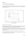
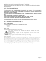
Chell Instruments Ltd
Folgate House
Folgate Road
North Walsham
Norfolk
ENGLAND
NR28 0AJ
+44 1692 500555
ILITS-3
Impulse Line Integrity
Test Set
INSTALLATION
AND
OPERATING MANUAL
e-mail:- [email protected]
Visit the Chell website at:
http://www.chell.co.uk
900107-1.1
Please read this manual carefully before using the instrument.
Use of this equipment in a manner not specified in this
manual may impair the user’s protection.
INDEX
Section 1
Section 2
Section 3
Section 4
Section 5
General Description
Specification
Installation and Interconnections
Operation
Service and Calibration
Chell Document No. : 900107 Issue 1.1
ECO No. 0537 Date: 17th Sep 2008
Chell’s policy of continuously updating and improving products means that this manual may contain
minor differences in specification, components and circuit design from the actual instrument
supplied.
Page 1
Section 1
General Description
The Impulse Line Integrity Test Set, ILITS-3, is manufactured to allow testing of the reactor
gas pressure measurement impulse lines.
Testing is done by injecting a constant known gas flow though a line and measuring the
pressure head required to maintain this flow.
The test set comprises an adjustable regulator on the rear panel to set the input pressure
to the internal mass flow controller. The output of the mass flow controller is used to pass
gas into the line to be tested. This output port pressure is monitored by an internal
capacitance manometer, measuring gauge pressure.
Both pressure head and mass flow are clearly displayed on the bright front panel displays.
The test set is fitted with an adjustable carry handle / desk stand to allow a degree of
portability.
Page 2
Section 2
2.0
Specification
2.1
Mechanical:
2.2
Package:
Size (enclosure):
Free standing desktop case, with prop-stand / handle
H 220mm, W 360mm, D 490 mm depth (exc. adapters)
Mounting:
Weight:
Free standing
14 Kg
Power Supply:
Line voltage:
Line frequency:
Consumption:
Protection:
2.3
240V AC or 120V AC. (Factory Set)
50 ~ 60 Hz.
less than 60 VA
1.6A anti surge fuse 20x5mm
Operating conditions:
Operating temperature range:
Storage temperature range:
Maximum Relative humidity:
Warm up time to full accuracy:
2.4
+5°C to +50°C (40°F to 122°F)
-20°C to +70°C (-40°F to 158°F)
95% at 50°C (non condensing)
30 minutes (assumes unit already stabilised at
ambient).
Pneumatic Interface:
3-7 bar(g)
Supply Pressure:
Type:
Clean, Dry preferred, but the unit is fitted with an external
filter / regulator.
Fitting:
Push-in type fitting to accept 12mm OD plastic tube.
(Ensure that the tube used is compatible with this SMC
Pneumatics fitting)
Outlet:
Flow:
Flow range:
Pressure:
Pressure range:
WARNING
Controlled air flow, Measured at 1% FS error.
150 slpm
Measured at 0.3% reading error
1000mb (g)
Damage may result if the pressure transducer is
exposed to pressure exceeding 1600 mb (g)
Page 3
Section 3
3.0
Installation and Interconnections
The instrument should operate free-standing on a flat level surface, such as a bench top.
Note that the instrument must always be located in such a way as to enable adequate air
circulation about the unit.
fig. 1 - Rear Panel
Services required by the test set are:
Mains Power: 110-120 VAC 50-60 Hz. An IEC 320 type socket lead is required to connect.
The mains voltage is factory set and a user should not attempt modification. Please consult
Chell Instruments Ltd if you require the voltage setting to be changed.
Air Supply: 12mm OD plastic tubing. Polyurethane or nylon is recommended. Metal tubing
or adapters are not suitable, unless it is specifically designed for use with the SMC range of
push-fit connections.
The unit should be powered for at least 30 minutes before use to obtain full accuracy.
Never place an obstruction or blanking plug in the outlet fitting of the test set. This may
result in equipment damage or personal injury.
Page 4
The user can gain access to an analogue retransmission of the displayed values via the
interface connector.
Interface socket Pin-out - 9 Way 'D' Type
Caution
Pin Number
1
2
3
4
Designation
+ Flow Signal
- Flow Signal
+ Pressure Signal
- Pressure Signal
All other pins
Not Connected
Check the Mains Supply is correct and suitable before
connection.
This equipment must be properly earthed.
Do not use this equipment if it is, or is suspected to be, wet or
near water, faulty or partially assembled.
Failure to follow advise given in this manual and/or on the
product may result in equipment damage, personal injury or
death.
Page 5
Section 4
4.0
Operation of the instrument
Before switching on the power, ensure that the correct mains supply voltage is connected.
After power on, the display will light. The actual value displayed will depend on the output
of the transducer. In an overrange condition the display flashes. It is recommended that
gas supply and test product not be connected until the test set is ready for use.
Allow 30 minutes warm-up before using for accurate measurement and control.
Warning
If there is a probability that the load to be tested is completely blocked or
blanked, the flow rate must be set to a low value initially, with the
regulator set to no more than 1.5 bar.
Failure to follow this procedure may result in permanent damage to the
pressure sensor. Once the status of the load has been ascertained
normal settings can be applied.
4.1
Front Panel Controls.
More detailed information may be found in the accompanying CCD100 user manual.
fig. 2 - Front Panel
4.1.1 Zero Trim
Before the test set is used, and after the 30 minute warm-up time has been observed, the
displays should be ‘zeroed’.
To do this ensure that the gas supply is disconnected, or the regulator is set to minimum,
Page 6
and there is no product connected to the output of the test set.
Press the zero button on each display and hold for 3 seconds. Any offset on the display
will be removed.
4.1.2 Flow Command (Setpoint)
The flow control may be adjusted but changing the flow setpoint. This is achieved by
pressing the up or down arrows as appropriate. The display will show the setpoint and the
actual flow on a two-line display.
The Flow mode can be changed between Open, Closed, and Auto by using the override
key:
Auto: Press Overide, then Auto (it’s the same key )
Close: Press Overide then Close. Note the display now shows ‘CLOSE’
Open: Press Overide the Open. Note the display shows ‘OPEN’
It is usual that the flow controller may take a few moments to commence control.
4.2
Rear Panel Controls (see fig.1 pg 4)
4.2.1 Power Switch
The mains switch is located next to the mains inlet cord.
0 = off
1 = on
4.2.2 Fuse
This is located next to the mains cord socket.
The mains cord must be removed in order to withdraw the fuse
compartment.
Do Not attempt to open the fuse compartment with the mains cord
attached.
Always replace the fuse with the correct type and rating.
4.2.3 Regulator
The inlet pressure regulator is located at the rear of the unit. To adjust this regulator, turn
the knob clockwise to increase the pressure and anti-clockwise to reduce the pressure.
Observe the dial gauge on the rear panel to check the inlet pressure. If the knob fails to
move easily it may be locked, pull the knob upward to unlock, press downward to lock.
It is recommended that a pressure of 1.5 bar is set for full scale flow. A pressure of this
value will help to protect the internal pressure transducer from damage.
Page 7
Section 5
Service and Calibration
5.1 Service
There are no user serviceable parts inside the instruments. Should any difficulties be
encountered in the use of the test set, it is recommended that you contact Chell
Instruments Ltd for advice and instructions.
5.2 Calibration
Calibration is recommended on an annual basis and Chell Instruments Ltd. Provides a fully
traceable facility for this purpose.
5.3 Adjustment
There are no user adjustments in the instrument, indeed, the presence of lethal voltages
within the instrument means that the user is strictly forbidden from removing the covers
without invalidating Chell’s obligations under both Warranty
and COSSH.
5.4 Cleaning
A dirty instrument may be wiped clean with a soft cloth that has been sprayed with a
proprietary ‘foaming cleaner’, then wiped dry immediately.
Under no circumstances should the instrument be wetted
directly or left damp.
Page 8