1
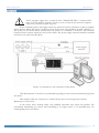
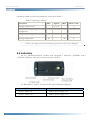
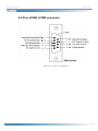
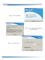
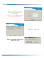
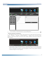
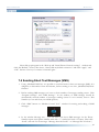
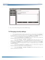
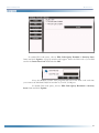
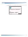
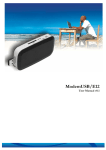
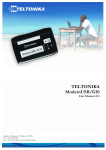
TELTONIKA ModemCOM/G10
(CM1100)
User Manual V0.1
ModemCOM/G10
Manual v0.1
Table of Contents
TABLE OF CONTENTS..........................................................................................................................2
1.
ATTENTION..................................................................................................................................3
2.
SAFETY INSTRUCTION ............................................................................................................3
3.
LEGAL NOTICE ...........................................................................................................................5
4.
INTRODUCTION .........................................................................................................................5
5.
PACKAGE CONTENTS..............................................................................................................5
6.
TECHNICAL SPECIFICATIONS..............................................................................................6
6.1 Data transferring ...............................................................................................................................6
6.2 Mechanical specifications.................................................................................................................6
6.3 Electrical and operating specifications...........................................................................................6
6.4 Indication............................................................................................................................................7
6.5 Pins of DB9 (COM) connector.......................................................................................................9
7.
MODEM SETUP ..........................................................................................................................10
7.1 Connecting to the computer..........................................................................................................10
7.2 Installation of “Modem Control Tool”........................................................................................10
7.3 Setting up an Internet connection ................................................................................................13
7.4 Sending Short Text Messages (SMS) ............................................................................................16
7.5 Changing security settings..............................................................................................................17
8.
ACRONYMS..................................................................................................................................21
9.
TECHNICAL SUPPORT............................................................................................................22
2
ModemCOM/G10
1.
Manual v0.1
ATTENTION
Do not rip the device. Do not touch the device if the device is
broken or his connecting wires are without isolation
All wireless devices for data transferring may be susceptible to
interference, which could affect performance.
Only qualified personnel may install or repair this product.
Your device is not water-resistant. Keep it dry.
2.
SAFETY INSTRUCTION
General safety requirements
In this document you will be introduced how to use the “ModemCOM/G10” device safely.
You will avoid dangerous situations and harming of yourself if you stick to these requirements and
recommendations. You have to be familiar with the safety requirements before starting using the
device!
To avoid burning and voltage caused traumas of the personnel working with the device, please
follow these safety requirements.
The device requires 9V power supply. The PC, to which the device “ModemCOM/G10” is to
be connected, must have a COM port. Nominal power supply voltage is 9 V. Available power supply
source range is 6 V … 32 V.
3
ModemCOM/G10
Manual v0.1
The PC and power supply source, to which the device “ModemCOM-TM2” is connected should
satisfy LST EN 60950-1 standards. The device can be used with the first (Personal Computer)
or the second (Notebook) computer safety class.
In the installation place and supply circuits the protective devices should be tooled up (bipolar
release device) which will protect the device from short-circuit and grounding troubles (Picture 1.1).
The power of the release device should satisfy the power of connected to it devices. The interstice
between release contacts should not be less than 3mm. The power supply network should be installed
near device on easily accessible place.
Picture 1.1. Scheme for safe connection of the device
Full disconnection of the device is performed by pulling out the constant current DC plug from
the device.
Data transfer cable for connection to another device must not be longer than 2 meters.
Maintenance of the device:
If the device starts working faulty only qualified personnel may repair this product. We
recommend dismantling the device and forwarding it tit repair center or to manufacturers. No
exchangeable parts in the device.
4
ModemCOM/G10
Manual v0.1
To avoid dangerous voltage effect, the power supply and the PC must be disconnected from the
electric network before starting dismantling it.
To use the devise needed:
AC/DC supply source. The power supply should be 6V@580mA to 32V@108mA.
3.
LEGAL NOTICE
Copyright © 2008 TELTONIKA Ltd.
All rights reserved. Reproduction, transfer, distribution or storage of part or all of the contents in this
document in any form without the prior written permission of TELTONIKA Ltd is prohibited.
Other product and company names mentioned herein may be trademarks or trade names of their
respective owners.
4.
INTRODUCTION
This document will provide you with the instructions how to install and use
„ModemCOM/G10“ and its software.
„ModemCOM/G10“ is a device designed for data transmission via GSM Network. The design of
this modem enables the connection to your PC through COM interface. „ModemCOM/G10“
supports the following data-bearers: GPRS, CSD, CSF and SMS.
5.
PACKAGE CONTENTS
„ModemCOM/G10“ is supplied to clients in carton with all contents, which are needed for
connection to PC and normal work.
Package contents:
1)
2)
3)
4)
5)
„ModemCOM/G10“ modem;
RS232 connecting cable;
CD with User’s Guide, drivers and Software;
External GSM antenna (just upon special orders);
AC/DC mains adapter.
Notice: the producer does not provide a SIM card among other items of a package, which is necessary
for connection to GSM Network! You can obtain a SIM card from your local GSM service provider!
If any of the components is missing please contact your local distributor.
5
ModemCOM/G10
Manual v0.1
6.
TECHNICAL SPECIFICATIONS
6.1 Data transferring
„ModemCOM/G10“ supports bearers presented below. Which data type is used depends on
GSM operator and data transfer capacity in the chosen GSM Network.
• GPRS class 10 (class B);
• CSD;
• CSF;
• SMS textual messages.
6.2 Mechanical specifications
„ModemCOM/G10“ housing is made of metal. It is light and durable – suitable for using in
home, office or industrial environment. The external dimensions and measures of the unit casing are:
100*60*31 mm.
6.3 Electrical and operating specifications
Acceptable voltage range is (6 ÷ 32)V DC. 9 V is a nominal value. The PC the
„ModemCOM/G10“ modem is connected to must have a RS232 (COM) interface.
Note: The device must be powered with AC/DC adapter provided by manufacturer.
Electrical parameters of the device are shown in the Table 1.
Table 1. Electrical parameters of the device
Parameter
Power Supply
Min
+6V
0.58A
Typical
+9V
0.39A
Max
+32V
0.1A
Average Power consumption
-
480 mW
-
Maximum Power consumption 1
-
3500 mW
-
6
ModemCOM/G10
Manual v0.1
Operating conditions and other parameters are shown in Table 2.
Table 2. Operating conditions
Parameter
Min
Typical
Max
Meas. Units
-
85 ± 10
-
g
Recommended operating
temperature
+15
-
+35
ºC
Marginal operating temperature
-20
-
+55
ºC
Storage temperature
-40
-
+85
ºC
Weight (modem only)
Notice: if the settings outreach the characteristics given above the device can be damaged!
6.4 Indication
On the „ModemCOM/G10“ modem were integrated 3 indicators: „POWER“ and 2
„STATUS“ indicators. They are located on the side of device.
A LED indicator “Power“ is located on the side of ModemCOM/G10.
“Power“ LED‘s Status
Modem status
„Power“ LED is on
Modem power supply is on
„Power“ LED is off
Modem power supply is off
7
ModemCOM/G10
Manual v0.1
A LED indicators “Status“ are located on the side of ModemCOM/G10.
“Status“ LEDs
LED Status
Modem Description
STATUS 1 (Green)
ON
Modem ready
STATUS 1 (Green)
Slow blink
Initialization
STATUS 1 (Green)
Double blink
Limited service PIN/PUK required
STATUS 2 (Orange)
Continuously blinking
Network absent
STATUS 2 (Orange)
Slow blink
GPRS fail
STATUS 2 (Orange)
Double blink
No SIM
Picture 2. Side view of „ModemCOM/G10“
Connectors:
• DB9 female for connection to the device;
• 3,5 mm/1,35 mm power supply connector;
• SIM card slot.
8
ModemCOM/G10
Manual v0.1
6.5 Pins of DB9 (COM) connector
Picture 6.5.1. Pins of COM port
9
ModemCOM/G10
Manual v0.1
7.
MODEM SETUP
7.1 Connecting to the computer
1)
2)
3)
4)
5)
6)
7)
Turn OFF your computer
Insert the SIM card into modem. Follow the instructions on the device sticker. Make
sure, the SIM card is pushed inside till it fixes.
Plug DB9 connector of the serial (RS232) cable into the modem.
Plug another end of the serial cable to one of the COM ports of PC.
Plug in the AC/DC adapter to power supply socket of “ModemCOM/G10”.
Plug in the AC/DC adapter to power supply network.
Turn ON your computer
7.2 Installation of “Modem Control Tool”
Step 1 - Open the “ModemCOM/G10”
Pack, take only the CD and insert it into
the PC CD Drive.
Step 2 – Wait till the system displays the
screen “Select Setup Language”.
Step 3 - Select English and Click “OK”
button.
Step 4 -Click “Install” button
10
ModemCOM/G10
Manual v0.1
Step 5 – Click “Next” button
Step 6 – Click “I Agree” button if agree with
License Agreement.
Step 7 - Click “Next” button
11
ModemCOM/G10
Manual v0.1
Step 8 - Enter dial-up connection
parameters and press “Next” in the
opened dialog.
Note: APN, user name and password are
to be asked to your GSM operator!
Step 9 - Click “Install” button.
Step 10 – Connect the modem to the PC
and click “OK” button.
12
ModemCOM/G10
Manual v0.1
Step 11 - Press “Finish” in the opened
dialog box “Modem Control tool Setup”.
Congratulations the installation is done.
7.3 Setting up an Internet connection
In this chapter we will provide you with general information and procedures necessary for setting
up an Internet connection in your PC. When using “Modem Control Tool”, the Internet connection
settings are determined automatically.
Before you begin make sure that:
•
You have a GSM SIM card with activated data transfer service;
•
“ModemCOM/G10“ is ready to work – SIM card is pushed in, the device is correctly
connected to the PC, the drivers are properly installed;
•
TCP/IP protocol is installed on your PC.
When you are using “ModemCOM/G10“ you can get access to the Internet via one of this data
transmission types:
•
GPRS packet data transfer. In this case you have to know “APN”, “user name and
password”;
•
CSD data transfer. You have to know a phone number of a dial-up server.
If GPRS data transfer is used, you have to set up an APN, if needed, user name and password.
1)
2)
3)
4)
5)
6)
7)
Start “Modem Control Tool”. If needed the PIN code, enter it;
Click “Settings” button
Select “Connection”;
Enter the APN;
Enter the Phone Number [*99#], if it is not entered automatically;
If needed, enter the User name and Password;
Click “Update”.
13
ModemCOM/G10
Manual v0.1
Note: ForAPN, user name and password – ask your GSM operator!
Getting connected to the Internet:
1. Start “Modem Control Tool” program. The program can be started from the PC desktop (or
“Start -> Programs -> Teltonika -> ModemCOM G10 -> Modem Control Tool G10“) while
clicking on the shortcut. When the shortcut will be clicked, “Modem Control Tool” dialog box
will be opened.
2. The program should automatically detect a connected modem. If you start the program
before connect modem, you have to wait till modem will be ready to work. If the program
does not detecting your modem restart the program; As well you may perform “Scan for
hardware changes” in some computers.
14
ModemCOM/G10
Manual v0.1
3. To connect to the Internet, click “Connect” button:
4. The modem starts connecting to Internet after clicking on this button. When the modem
connected to Internet, you will see message “Disconnect”;
If you can not connect the Internet using Internet Explorer after using Modem follow these
steps, click Start → Settings → Control Panel → Internet Options. Select the box “Connections” in
the appeared dialogue box “Internet Properties”.
15
ModemCOM/G10
Manual v0.1
Select dial-up pictogram in the “Dial-up and Virtual Private Network settings” window and
click “Set Default” button, then chose “Always dial my default connection” and click “Apply” and
“OK” buttons. Now try to connect to Internet again.
7.4 Sending Short Text Messages (SMS)
1. Using „ModemCOM/G10“ it is possible to send and receive short text messages (SMS). It is
obligatory to disconnect from the Internet, before starting to use this „ModemCOM/G10“
function.
2. Before sending SMS messages you have to check number of messages sending center. Click
“Program Settings” and “SMS Settings”. In the window of SMS Settings should be
automatically entered number of messages sending center if it not entered, enter it. This
Number you can ask from your GSM operator;
3. Click “SMS” button on “Modem Control Tool” window for writing and reading of SMS
messages:
4. In the window Message text – you can write your short SMS messages. In the Phone
Number square enter phone number with with “+” symbol and code of country. Then click
“Send”, and wait for the message: “Message Sent Successful” or “Message Was Not Sent”;
16
ModemCOM/G10
Manual v0.1
5. Also you can read incoming and sent short SMS messages.
7.5 Changing security settings
To set ModemCOM/G10 modem parameters or to change them, click Settings in
the main Modem Control Tool window. If you click Main in the Settings window, you
will be able to choose a modem from the list of modems installed in your PC.
If you click Connection in the Settings window, you will be able to change the
ModemCOM/G10 modem Internet connection parameters.
If you click Settings → Security, a Security window will open where you can
enable or disable PIN code query. To set ModemCOM/G10 modem parameters or to
change them, click Settings in the main Modem Control Tool window. If you click Main
in the Settings window, you will be able to choose a modem from the list of modems
installed in your PC.
If you click Connection in the Settings window, you will be able to change the
ModemCOM/G10 modem Internet connection parameters.
If you click Settings → Security, a Security window will open where you can
enable or disable PIN code query.
17
ModemCOM/G10
Manual v0.1
To enable PIN code query, choose PIN Code Query Enabled in Security State
frame and click Update. A pop-up window will appear. Enter the PIN code of your SIM
card in the Insert Pin Code field and click OK.
Now, the Modem Control Tool program will ask for the PIN code each time
you connect the ModemCOM/G10 modem to your PC COM port
To disable PIN code query, choose PIN Code Query Disabled in Security
State frame and click Update.
18
ModemCOM/G10
Manual v0.1
SMS center number is shown in Settings → SMS.
To change Modem Control Tool program language, go to Settings →
Application. In Application window choose the language from Set Language field and
click Update Language.
19
ModemCOM/G10
Manual v0.1
Click About to see the Modem Control Tool program version and other
Information.
.
20
ModemCOM/G10
8.
Manual v0.1
ACRONYMS
AC/DC
Alternating Current/Direct Current
APN
Access Point Name
CSD
Circuit Switched Data
CSF
Circuit Switched Fax
GPRS
General Packet Radio Service
GSM
Global System for Mobile communications
IMEI
International Mobile Equipment Identity
ISP
Internet Service Provider
LED
Light Emitting Diode
OS
Operating System
PDP
Packet Data Protocol
PIN
Personal Identification Number
SIM
Subscriber Identity Module
SMS
Short Message Service
TCP/IP
Transmission Control Protocol/Internet Protocol
21
ModemCOM/G10
9.
Manual v0.1
TECHNICAL SUPPORT
This sign on the package means that it is necessary to read a User Manual, which is
on the CD before you start using the device.
This sign on the package means, that used electronic and electric equipment should
be stored separately.
If you have faced some problems using the device, which you are not able to solve by yourself,
you are always welcome to address our technical support department by e-mail [email protected] .
We will be very glad to help you.
H
H
22