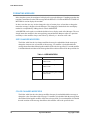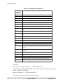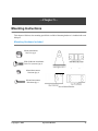
1
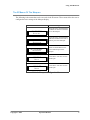
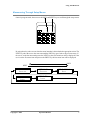
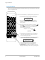
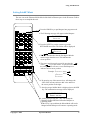
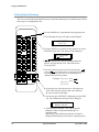
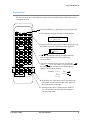
Your Corporate Logo Here
Operation Manual
Model Number: MM-0XXX-T
V2.0
Copyright © 2006 DataVisor Marquees Inc.
Using The IR Remote . . . . . . . . . . . . . . . . . . . . . . . . . . . . . . . . . . . . . . . . . . . . . . . . . . . . . . . .
Key Usage Of IR Remote . . . . . . . . . . . . . . . . . . . . . . . . . . . . . . . . . . . . . . . . . . . . . . . . . . . . . .
The IR Menus Of The Marquee . . . . . . . . . . . . . . . . . . . . . . . . . . . . . . . . . . . . . . . . . . . . . . . . . .
Programing With The IR Remote . . . . . . . . . . . . . . . . . . . . . . . . . . . . . . . . . . . . . . . . . . . . . . . .
Entering Into Program Mode . . . . . . . . . . . . . . . . . . . . . . . . . . . . . . . . . . . . . . . . . . . . . . . . . . . .
Maneuvering Through Setup Menus . . . . . . . . . . . . . . . . . . . . . . . . . . . . . . . . . . . . . . . . . . . . . .
Setting IP Address . . . . . . . . . . . . . . . . . . . . . . . . . . . . . . . . . . . . . . . . . . . . . . . . . . . . . . . . . . . .
Setting SubNET Mask . . . . . . . . . . . . . . . . . . . . . . . . . . . . . . . . . . . . . . . . . . . . . . . . . . . . . . . . .
Setting Default Gateway . . . . . . . . . . . . . . . . . . . . . . . . . . . . . . . . . . . . . . . . . . . . . . . . . . . . . . .
Setting Time . . . . . . . . . . . . . . . . . . . . . . . . . . . . . . . . . . . . . . . . . . . . . . . . . . . . . . . . . . . . . . . . .
Setting Date . . . . . . . . . . . . . . . . . . . . . . . . . . . . . . . . . . . . . . . . . . . . . . . . . . . . . . . . . . . . . . . . .
3
4
5
6
6
7
8
9
10
11
12
Making The Ethernet Connection . . . . . . . . . . . . . . . . . . . . . . . . . . . . . . . . . . . . . . . . . . . .
Quick Setup . . . . . . . . . . . . . . . . . . . . . . . . . . . . . . . . . . . . . . . . . . . . . . . . . . . . . . . . . . . . . . . . . . . .
Required Equipment. . . . . . . . . . . . . . . . . . . . . . . . . . . . . . . . . . . . . . . . . . . . . . . . . . . . . . . . . . .
Steps To Connect The Marquee Via Ethernet . . . . . . . . . . . . . . . . . . . . . . . . . . . . . . . . . . . . . . .
Detailed Ethernet Setup . . . . . . . . . . . . . . . . . . . . . . . . . . . . . . . . . . . . . . . . . . . . . . . . . . . . . . . . . . .
Configuring the PC . . . . . . . . . . . . . . . . . . . . . . . . . . . . . . . . . . . . . . . . . . . . . . . . . . . . . . . . . . .
Using IPCONFIG To Verify Ethernet Settings . . . . . . . . . . . . . . . . . . . . . . . . . . . . . . . . . . . . . .
Connecting The PC To The Marquee. . . . . . . . . . . . . . . . . . . . . . . . . . . . . . . . . . . . . . . . . . . . . .
Verifying Ethernet Communications . . . . . . . . . . . . . . . . . . . . . . . . . . . . . . . . . . . . . . . . . . . . . .
Connecting To the Marquee’s WEB Server . . . . . . . . . . . . . . . . . . . . . . . . . . . . . . . . . . . . . . . . .
13
14
14
14
16
16
20
22
24
27
Marquee WEB Pages . . . . . . . . . . . . . . . . . . . . . . . . . . . . . . . . . . . . . . . . . . . . . . . . . . . . . . . . .
31
31
32
33
34
36
38
40
MAIN PAGE . . . . . . . . . . . . . . . . . . . . . . . . . . . . . . . . . . . . . . . . . . . . . . . . . . . . . . . . . . . . . . . .
Access Configuration Pages. . . . . . . . . . . . . . . . . . . . . . . . . . . . . . . . . . . . . . . . . . . . . . . . . . . . .
SETUP MENU. . . . . . . . . . . . . . . . . . . . . . . . . . . . . . . . . . . . . . . . . . . . . . . . . . . . . . . . . . . . . . .
DISPLAY CONFIGURATION . . . . . . . . . . . . . . . . . . . . . . . . . . . . . . . . . . . . . . . . . . . . . . . . . .
NETWORK CONFIGURATION . . . . . . . . . . . . . . . . . . . . . . . . . . . . . . . . . . . . . . . . . . . . . . . .
TIME SETTINGS PAGE . . . . . . . . . . . . . . . . . . . . . . . . . . . . . . . . . . . . . . . . . . . . . . . . . . . . . . .
BACKUP AND RESTORE PAGE . . . . . . . . . . . . . . . . . . . . . . . . . . . . . . . . . . . . . . . . . . . . . . .
UDP MESSAGING . . . . . . . . . . . . . . . . . . . . . . . . . . . . . . . . . . . . . . . . . . . . . . . . . . . . . . . . . . . .
WHAT IS UDP? . . . . . . . . . . . . . . . . . . . . . . . . . . . . . . . . . . . . . . . . . . . . . . . . . . . . . . . . . . . . . .
HOW IS UDP IMPLEMENTED IN THE MARQUEE? . . . . . . . . . . . . . . . . . . . . . . . . . . . . . .
FORMATING MESSAGE. . . . . . . . . . . . . . . . . . . . . . . . . . . . . . . . . . . . . . . . . . . . . . . . . . . . . .
DISPLAY METHOD MODIFIERS. . . . . . . . . . . . . . . . . . . . . . . . . . . . . . . . . . . . . . . . . . . . . . .
SPECIAL MODIFIERS . . . . . . . . . . . . . . . . . . . . . . . . . . . . . . . . . . . . . . . . . . . . . . . . . . . . . . . .
Mounting Instructions . . . . . . . . . . . . . . . . . . . . . . . . . . . . . . . . . . . . . . . . . . . . . . . . . . . . . . .
Mounting Hardware Included . . . . . . . . . . . . . . . . . . . . . . . . . . . . . . . . . . . . . . . . . . . . . . . . . . .
Installing Mount Attachment Bolts . . . . . . . . . . . . . . . . . . . . . . . . . . . . . . . . . . . . . . . . . . . . . . .
Mounting Method Samples . . . . . . . . . . . . . . . . . . . . . . . . . . . . . . . . . . . . . . . . . . . . . . . . . . . . .
Copyright © 2006
Operation Manual
41
41
41
42
43
44
47
47
48
49
1
2
Operation Manual
Copyright © 2006
—Chapter 1—
Using The IR Remote
This chapter will discuss the use to the IR remote. The remote is used to initially set the Network
Parameters, Time and Date. It can also be used during operation to allow for resetting of process
variables.
PROG
CPW
PREV
NEXT
MET
TIME
FONT
COL
PAU
SPE
CAP
SYM
GRA
PHR
CLR
BEEP
DEL
ENT
INS
ESC
RUN
Copyright © 2006
A
B
C
D
E
F
G
H
I
J
K
L
M
N
O
P
Q
R
S
T
U
V
W
X
Y
Z
1
2
3
4
5
6
7
8
9
0
ALT
Operation Manual
3
Using The IR Remote
Key Usage Of IR Remote
There are many keys that are not currently used for the operation of the Marquee display. The
following lists the keys that have operation capability with the marquee.
KEY
PROG
USAGE
Enter Program Mode
PREV
Go To Previous Program Screen
NEXT
Go To Next Program Screen
Move Cursor To Left
Move Cursor To Right
RUN
Return to Operating Mode
Y
Used For Conformation Of Change
N
Used for Rejection Of Change
0-9
Numeric Keys For Data Entry
Table 1—IR Remote Key Usage
4
Operation Manual
Copyright © 2006
Using The IR Remote
The IR Menus Of The Marquee
The following is the menus that can be accessed via the IR remote. These menus allow the user to
configure the basic settings of the Marquee display.
Menu
Usage
IP ADDRESS
192.168.1.200
NET MASK
255.255.255.000
SET GATEWAY
000.000.000.000
SET TIME
02:47:37
SET DATE
06/10/06
Allows the user to set the Ethernet
IP address for the built in ethernet
port of the Marquee.
Allows the user to set the Ethernet
SUB NET MASK for the built in
Ethernet port of the Marquee.
Allows the user to set the Ethernet
DEFAULT GATEWAY for the
built in Ethernet port of the
Marquee.
Allows the user to set the TIME
for the built in real time clock of
the Marquee.
Allows the user to set the DATE
for the built in real time clock of
the Marquee.
Table 2—Marquee Configuration Menus
Copyright © 2006
Operation Manual
5
Using The IR Remote
Programing With The IR Remote
The following section will describe the steps that are taking in order to enter program mode and
accessing the Marquee setup menus. In this section the user will be instructed on how to accomplish
the following tasks.
• Set the Ethernet parameters of the Marquee
• Set the Time and Date on the Marquee display
Entering Into Program Mode
In order to access the setup menus the user must put the Marquee into program mode. This is a
simple as pressing the PROG key on the IR remote.
PROG
CPW
PREV
NEXT
MET
TIME
FONT
COL
The follow message will be displayed on the Marquee.
IP ADDRESS
192.168.1.200
Note: The user should be within 20 Ft of the Marquee in order for IR operations!
6
Operation Manual
Copyright © 2006
Using The IR Remote
Maneuvering Through Setup Menus
Ounce in program mode, the user uses the PREV and NEXT keys to scroll through the setup menus.
PROG
CPW
PREV
NEXT
MET
TIME
FONT
COL
PAU
SPE
CAP
SYM
GRA
PHR
CLR
BEEP
DEL
ENT
By using these keys the user can select the menu item that is desired and take appropriate action. The
NEXT key takes the user to the next menu and the PREV key goes back to the previous menu. If
the user is on the last menu and presses the NEXT key the first menu item will be displayed. If the
user is on the first menu item and presses the PREV key the last menu item will be displayed.
PREV
NEXT
IP ADDRESS
192.168.1.200
NET MASK
255.255.255.0
SET TIME
12:10:05
SET DATE
10/10/06
Copyright © 2006
Operation Manual
SET GATEWAY
0.0.0.0
7
Using The IR Remote
Setting IP Address
The user can set the Ethernet IP address of the built in Ethernet port via the IR remote. Follow these
steps to accomplish this task.
1. Press the PROG key to put Marquee into program mode.
PROG
CPW
PREV
NEXT
MET
TIME
FONT
COL
PAU
SPE
CAP
SYM
GRA
PHR
CLR
BEEP
DEL
ENT
INS
ESC
RUN
A
B
C
D
E
F
G
H
I
J
K
L
M
N
O
P
Q
R
S
T
U
V
W
X
Y
Z
1
2
3
4
5
6
7
8
9
0
2. The Following message will appear on the Marquee.
IP ADDRESS
192.168.1.200
3. The user should notice that the first digit within the
IP address is larger than the reset. This indicates the
cursor position.
4. The cursor position can be moved by pressing the
or the
key of the remote. As you move the cursor
the enlarged value will move across the Marquee to
indicate current cursor position.
Example: 192.168.1.200 Press
192.168.1.200 Press
192.168.1.200
5. By pressing any of the numeric keys will change the
value of the current position to that value and move
the cursor position to the right.
ALT
6. Once the proper IP address is displayed press the RUN
key. The confirmation message will be displayed.
ACCEPT NEW IP
PRESS Y FOR YES
7. At this point pressing the Y key will change the
Marquees IP address and return the Marquee to
operating mode.
If the N key is pressed then the IP address will not be
changed and the Marquee will return to operating mode.
8
Operation Manual
Copyright © 2006
Using The IR Remote
Setting SubNET Mask
The user can set the Ethernet SubNet Mask of the built in Ethernet port via the IR remote. Follow
these steps to accomplish this task.
1. Press the PROG key to put Marquee into program mode.
PROG
CPW
PREV
NEXT
2. The Following message will appear on the Marquee.
MET
TIME
FONT
COL
PAU
SPE
IP ADDRESS
192.168.1.200
CAP
SYM
GRA
PHR
CLR
BEEP
DEL
ENT
INS
ESC
RUN
A
B
C
D
E
F
G
H
I
J
K
L
M
N
O
P
Q
R
S
T
U
V
W
X
Y
Z
1
2
3
4
5
6
7
8
9
0
ALT
3. Press the NEXT key on the remote to go to the
NET MASK menu item. The follow will be displayed.
NET MASK
255.255.255.0
4. The user should notice that the first digit within the
mask is larger than the reset. This indicates the
cursor position.
5. The cursor position can be moved by pressing the
or the
key of the remote. As you move the cursor
the enlarged value will move across the Marquee to
indicate current cursor position.
Example: 255.255.255.0 Press
255.255.255.0
Press
255.255.255.0
6. By pressing any of the numeric keys will change the
value of the current position to that value and move
the cursor position to the right.
7. Once the proper SubNet Mask is displayed press the RUN
key. The confirmation message will be displayed.
ACCEPT NEW IP
PRESS Y FOR YES
8. At this point pressing the Y key will change the
Marquees Subnet Mask and return the Marquee to
operating mode.
If the N key is pressed then the Subnet Mask will not be
changed and the Marquee will return to operating mode.
Copyright © 2006
Operation Manual
9
Using The IR Remote
Setting Default Gateway
The user can set the Ethernet Default Gateway of the built in Ethernet port via the IR remote. Follow
these steps to accomplish this task.
1. Press the PROG key to put Marquee into program mode.
PROG
CPW
PREV
NEXT
MET
TIME
FONT
COL
PAU
SPE
CAP
SYM
GRA
PHR
CLR
BEEP
DEL
ENT
INS
ESC
RUN
A
B
C
D
E
F
G
H
I
J
K
L
M
N
O
P
Q
R
S
T
U
V
W
X
Y
Z
1
2
3
4
5
6
7
8
9
0
ALT
2. The Following message will appear on the Marquee.
IP ADDRESS
192.168.1.200
3. Press the NEXT key two times on the remote to go to the
GATEWAY menu item. The follow will be displayed.
SET GATEWAY
0.0.0.0
4. The user should notice that the first digit within the
gateway is larger than the reset. This indicates the
cursor position.
5. The cursor position can be moved by pressing the
or the
key of the remote. As you move the cursor
the enlarged value will move across the Marquee to
indicate current cursor position.
Example: 255.255.255.0 Press
255.255.255.0
Press
255.255.255.0
6. By pressing any of the numeric keys will change the
value of the current position to that value and move
the cursor position to the right.
7. Once the proper GATEWAY is displayed press the RUN
key. The confirmation message will be displayed.
ACCEPT NEW IP
PRESS Y FOR YES
8. At this point pressing the Y key will change the
Marquees Gateway and return the Marquee to
operating mode.
If the N key is pressed then the Gateway will not be
changed and the Marquee will return to operating mode.
10
Operation Manual
Copyright © 2006
Using The IR Remote
Setting Time
The user can set the time of the built in real time clock via the IR remote. Follow these steps to
accomplish this task.
1. Press the PROG key to put Marquee into program mode.
PROG
CPW
PREV
NEXT
MET
TIME
FONT
COL
PAU
SPE
CAP
SYM
GRA
PHR
CLR
BEEP
DEL
ENT
INS
ESC
RUN
A
B
C
D
E
F
G
H
I
J
K
L
M
N
O
P
Q
R
S
T
U
V
W
X
Y
Z
1
2
3
4
5
6
7
8
9
0
ALT
2. The Following message will appear on the Marquee.
IP ADDRESS
192.168.1.200
3. Press the NEXT key three times on the remote to go to the
SET TIME menu item. The follow will be displayed.
SET TIME
12:10:05
4. The user should notice that the first digit within the
time is larger than the reset. This indicates the
cursor position.
5. The cursor position can be moved by pressing the
or the
key of the remote. As you move the cursor
the enlarged value will move across the Marquee to
indicate current cursor position.
Example: 12:10:05
2
1 :10:05
Press
Press
12:10:05
6. By pressing any of the numeric keys will change the
value of the current position to that value and move
the cursor position to the right.
7. Once the proper Time is displayed press the RUN
key which set the new time and put the Marquee
into operating mode.
Copyright © 2006
Operation Manual
11
Using The IR Remote
Setting Date
The user can set the date of the built in real time clock via the IR remote. Follow these steps to
accomplish this task.
1. Press the PROG key to put Marquee into program mode.
2. The Following message will appear on the Marquee.
IP ADDRESS
192.168.1.200
3. Press the NEXT key four times on the remote to go to the
SET TIME menu item. The follow will be displayed.
SET DATE
10/10/06
4. The user should notice that the first digit within the
date is larger than the reset. This indicates the
cursor position.
5. The cursor position can be moved by pressing the
or the
key of the remote. As you move the cursor
the enlarged value will move across the Marquee to
indicate current cursor position.
Example: 10/10/06
Press
1 0/10/06
Press
10/10/06
6. By pressing any of the numeric keys will change the
value of the current position to that value and move
the cursor position to the right.
7. Once the proper Time is displayed press the RUN
key which set the new date and put the Marquee
into operating mode.
12
Operation Manual
Copyright © 2006
—Chapter 2—
Making The Ethernet Connection
This chapter describes the steps that are taking in order to connect the Marquee to an ethernet network
or configuration PC to allow the configuration of the Marquee.
In most cases, the first step in configuring the Marquee is physically connecting the Marquee to what is
known as a configuration PC. A configuration PC can be a laptop or desk-top PC that is equipped with
an ethernet port and has WEB browser software installed. There are many different WEB browsers
available on the market today. Please refer to the documentation for WEB browser that is being used if
it is not clear what is needed to be accomplished.
The Marquee can be connected directly to a PC’s ethernet port or connected to the facility network. It
is recommended that the first time a user connects to the user connects directly to the Marquee and does
not connect to the facility network. By connecting directly, the user has more control over the ethernet
network settings and the need to consult with the IT department or network administrator of the facility.
Note: Prior to connecting to the facility network, it is highly recommended to consult the facility
IT department or the network administrator of the facility.
Copyright © 2002
BookNameHere
13
Making The Ethernet Connection
Quick Setup
Quick Setup
This section is designed for the user who is familiar with connecting devices via ethernet. This section
assumes a direct connection between the ethernet port of a PC and the Ethernet port of the Marquee.
If the user is not familiar with connecting ethernet devices or configuring ethernet Parameters of the PC
it is highly recommended to go to the section Detailed Ethernet Setup section.
Required Equipment
• DataVisor Marquee
• PC with Ethernet port and a Web browser installed
Note: The user must have administrator rights on the PC
• An Ethernet cross cable or a switch with an Ethernet patch cable.
Steps To Connect The Marquee Via Ethernet
These steps use the factory default ethernet parameters that are set in the Marquee.
• IP Address 192.168.1.200
• Subnet Mask 255.255.255.0
1. Connect a ethernet cross-over cable between the PC and the Marquee
Marquee Ethernet Port
2. Apply power to the Marquee
120 Vac Power Connection
14
BookNameHere
Copyright © 2002
Making The Ethernet Connection
Quick Setup
3. Power the PC
4. Configure the PC’s ethernet port.
• IP address 192.168.1.100
• SubNet Mask 255.255.255.
Note: Refer to the section Set the PC for Fixed IP Address for detailed instructions.
4. Start the WEB browser application and enter the IP address of the Marquee in the address field.
In the address bar type http://192.168.1.200 then preset the ENTER key
http://192.168.1.200
Note: On many browsers the http:// is automatically added to the address so the user
does not need to type it in.
6. At this point the MONITOR page of the Marquee should be displayed in Internet Explorer
7. The user may now access the configuration WEB pages of the Marquee.
Note: Please refer to the section Marquee Configuration Pages for details on the
configuration pages.
If the user has problems accessing the Marquee’s WEB pages, please follow the detailed steps in the
following section.
Copyright © 2002
BookNameHere
15
Making The Ethernet Connection
Detailed Ethernet Setup
Detailed Ethernet Setup
This section describes in detail the steps to establish an ethernet connection to the Marquee in order to
configure it’s operation. This section assumes the user will be using the default ethernet settings
Marquee. If the user changes the default ethernet settings, such as the IP address, the user must use the
new settings in place of the defaults when referenced in this section.
• Default IP address of Marquee 192.168.1.200
• Default SubNet Mask of Marquee 255.255.255.0
• Default Gateway of Marquee 0.0.0.0
This section is for connecting the Marquee directly to the PC. If the user wishes to connect the Marquee
to the facility network, it is highly advised that the network administrator or IT department is involved.
This is suggested so as the Ethernet network parameters of the Marquee can be configured to match the
facility network parameters.
Configuring the PC
The first step in making an Ethernet connection to the Marquee is to configure the PC so as the
Ethernet port of the PC can communicate to the Marquee. After the PC has been powered up follow
these steps to verify the configuration of the PC.
Note: Prior to making changes to the ethernet configuration of the PC the existing
configuration should be documented. The user may be required to revert back to the
existing configuration in order to connect to the facility network.
16
BookNameHere
Copyright © 2002
Making The Ethernet Connection
Detailed Ethernet Setup
Set the PC for a Fixed IP Address WINDOWS XP
Many facility networks in use today use what is known as DHCP to allow a server on the
network to assign ethernet parameters to the PCs that are connected to the network. When
connecting directly from the PC to another ethernet device such as the Marquee, the user must
assign the Ethernet parameters of the PC manually.
Step 1
On the PC, click on START followed by CONTROL PANEL.
Note: Depending on the operation system of the PC the user may need to select
SETTINGS in order to access the CONTROL PANEL.
CONTROL
PANEL
START
Step 2
In Control Panel double click on NETWORK CONNECTIONS.
Copyright © 2002
BookNameHere
17
Making The Ethernet Connection
Detailed Ethernet Setup
Step 3
Under NETWROK CONNECTIONS find the ICOn that says LOCAL AREA NETWORK.
Then double click on this ICON.This allows the user to configuration the PCs ethernet port.
Step 4
One of two screens will be displayed. If the screen 1 is displayed, click the PROPERTIES
button and screen 2 will be displayed.
SCREEN TYPE 1
SCREEN TYPE 2
Properties Button
STEP 5
Select selection INTERNET PROTOCOL (TCP/IP) in the THIS CONNECTION USES
THE FOLLOWING ITEMS box. Then click the PROPERTIES button.
SELECT THIS
ENTRY
PROPERTIES
BUTTON
18
BookNameHere
Copyright © 2002
Making The Ethernet Connection
Detailed Ethernet Setup
STEP 6
The properties for the TCP/IP communications is displayed. If the window looks like the
screen below then the PC is set for connecting to as DHCP server. This means that the PC’s
ethernet parameters are generated by a DHCP server on the facility network. In order to
make a direct connection to the Marquee the user must manually enter the Ethernet
parameters. To accomplish this first select the item USE THe FOLLOWING IP ADDRESS.
At this point the user will enter the IP address 192.168.1.100 and the SUbNet Mask of
255.255.255.0.
After entry is completed click the OK button on each of the Network windows. This will
cause the PC to accept the changes and reconfigure the local Ethernet port.
Select
Enter IP address
and Subnet Mask
Click OK
Click OK
Click Close
NOTE: THIS SCREEN MAY
NOT BE DISPLAYED
Copyright © 2002
BookNameHere
19
Making The Ethernet Connection
Detailed Ethernet Setup
Using IPCONFIG To Verify Ethernet Settings
This section is used to verify that the local Ethernet port of the PC is configured properly. In this
section a detail description of the use of the IPCONFIG utility is demonstrated.
STEP1
From the START menu click on the RUN operation.
RUN operation
START
STEP 2
The RUN command entry box will appear. Enter CMD into the open field of this window
then click the OK Button. This will allow the user access to the command line entry prompt
of WINDOWS.
TYPE CMD
20
CLICK OK
BookNameHere
Copyright © 2002
Making The Ethernet Connection
Detailed Ethernet Setup
STEP 3
At this point the command line entry is displayed. At the Command Prompt type
IPCONFIG and then press the ENTER key of the keyboard.
Type IPCONFIG then press the ENTER key
The Ethernet parameters of the PC’s Ethernet port will be displayed. Verify that the IP
address and Subnet mask match the entries previously entered. If the parameters do not
match type:
• Verify that the parameters were entered correctly in the Network Properties window
from the previous procedure.
• Reboot the PC and repeat this procedure.
Note: If the user is unable to successfully set the Ethernet parameters please consult
the facility IT department or network administrator.
Ethernet Parameters for Local Port
Copyright © 2002
BookNameHere
21
Making The Ethernet Connection
Detailed Ethernet Setup
Connecting The PC To The Marquee
Cable Description
This section discussing the steps to connect the Marquee directly to the Marquee.
There are two types of Ethernet cables available in today’s market.
A patch or straight cable is used when connecting an Ethernet device to a Switch or HUB.
A Cross Over cable is used when connecting one Ethernet Device, such as a PC, to another Ethernet
Device, such as the Marquee, without a HUB or Switch. This is known as a direct connection and
requires that the Ethernet cable crosses the Ethernet signals. A Cross Over cable is included with the
Marquee for this purpose. If the user is connecting the Marquee to a HUB or Switch, the user must
supply the Patch or Straight Through cable.
Figure 1—Ethernet Cable Pinouts
22
BookNameHere
Copyright © 2002
Making The Ethernet Connection
Detailed Ethernet Setup
Connecting the Ethernet Cable
Prior to connecting the Marquee to the PC, both the PC and Marquee should be power down.
Connect the Cross cable to the Ethernet port of the marquee. The Ethernet port is located on the
right side of the Marquee.
Back of Marquee
Ethernet Port
120 Vac Power Connection
Connect the other end of the Cross cable to the PC’s Ethernet Port.
PC’s Ethernet
Port
Marquee Ethernet Port
Power up both the PC and Marquee. After the PC has booted the user should check for the LINK
light of the PC’s Ethernet port is Lit.The LINK light is lit when a physical connection is made
between the PC’s ethernet port and another Ethernet device, such as the Marquee. If the LINK
light is lit then the PC is properly connected to the Marquee.
If the LINK light is not lit check the following:
• Verify the Marquee is powered
• Verify the cable is a cross over cable
• Verify the Ethernet port of the PC is Enabled
Link Light
Copyright © 2002
Transmit Light
BookNameHere
23
Making The Ethernet Connection
Detailed Ethernet Setup
Verifying Ethernet Communications
The previous section verified the physical connection between the Ethernet port to the PC and the
Marquee. This section will be used to verify a communication connection exist between the
Marquee and the PC.
In order to communicate to the Marquee a communication connection must be established. The
physical connection indicates that communication can physically occur but does not verify that the
Ethernet parameters match between the Marquee and the PC. This section is used to verify the
Ethernet Parameters of both the PC and Marquee.
STEP 1
On the PC, click START followed by RUN.
RUN operation
START
24
BookNameHere
Copyright © 2002
Making The Ethernet Connection
Detailed Ethernet Setup
STEP 2
The RUN command entry box will appear. Enter CMD into the open field of this window
then click the OK Button. This will allow the user access to the command line entry prompt
of WINDOWS.
TYPE CMD
CLICK OK
STEP 3
At this point the command line entry is displayed. At the Command Prompt type
PING 192.168.1.200 and then press the ENTER key of the keyboard. This operation sends
a low level command to verify that communications can be established. The follow screen
shots display the three different responses that may occur during this operation alone with
the a description of the response.
Reply From
This is an indication that Ethernet communication is established to the Marquee.Proceed to
nest section.
Copyright © 2002
BookNameHere
25
Making The Ethernet Connection
Detailed Ethernet Setup
Request timed out
This indicates that the a connection to the Marquee could not be established.
• Verify the IP address and Subnet Mask is correct on the Marquee
• Verify cabling and LINK light is lit
• Verify Ethernet settings of PC
Response
Destination Host Unreachable
This is an indication that the PC’s Ethernet settings are not correct. This is a common error
when the IP address or Subnet mask is set incorrectly.
• Verify the PC’s Ethernet settings
• Reboot pc
26
BookNameHere
Copyright © 2002
Making The Ethernet Connection
Detailed Ethernet Setup
Connecting To the Marquee’s WEB Server
In this section a detailed explanation of the steps that are used to access the built in WEB sever of
the Marquee.
There are many different WEB browser software packages available on the market today. In this
section a general overview of WEB browser settings is discussed. Most WEB browser support the
settings discussed in this section, the user should reference documentation specific to the WEB
browser that is being used to determine how settings are configured within a giving WEB browser.
Note:
In most cases no setting changes are required to the WEB browser. Only in specific
cases is this required.
Step 1
Start the WEB Browser on the PC.
Step 2
In the Address Bar type HTTP://192.168.1.200.
Note: 192.168.1.200 is the default IP address of the Marquee. If this has been
changed by the user, change the IP address to match the IP address of the
Marquee.
http://192.168.1.200
Note: On many browsers the http:// is automatically added to the address so the
user does not need to type it in.
Step 3
At this point one of two items will be displayed in the WEB Browser.
Marquee’s Monitor Screen Appears
This is an indication that the WEB browser has established a connection to the Marquee’s
WEB server. The user can now proceed to configure the Marquee.
Copyright © 2002
BookNameHere
27
Making The Ethernet Connection
Detailed Ethernet Setup
No Monitor Page is Displayed
The Monitor page is not displayed and a message such as WEB PAGE CAN NOT BE
LOADED or FOUND. This error can be caused by the WEB browser’s settings not being
configured properly. The most common reasons for this error are listed below.
Note: It is assumed the user has followed the proceeding sections to verify Ethernet
communication to the Marquee. If not please refer to these sections to verify
that the Ethernet settings of the PC are correct.
WEB browser using wrong Ethernet Connection
In many PCs, such as a laptop, more than one Ethernet connection exists. In many cases a
wireless Ethernet connection exist on the PC and because of this the WEB browser uses this
connection as the default Ethernet Connection.
The solution for this is to DISABLE all Ethernet connections except the LOCAL Ethernet
port.
STEP 1
Click on START followed by Control Panel.
Control Panel
START
STEP 2
Click on NETWORK CONNECTIONS.
28
BookNameHere
Copyright © 2002
Making The Ethernet Connection
Detailed Ethernet Setup
STEP 3
Right click on each Network connection other than the LOACL CONECTION and select
DISABLE.
STEP 4
Restart PC and then restart the WEB browser.
WEB Browser Using Proxy server
In many facility networks, the WEB browser does not make a direct connection to the
Internet. In these cases a PROXY server is connected to the network and the WEB server
connects to this PROXY server to access WEB pages. When directly connecting to a WEB
server, such as the Marquee this setting within the WEB browser must be turned off. Follow
these steps to disable the PROXY server.
STEP 1
Open the WEB browser.
STEP 2
Within the WEB browser select TOOLS followed by INTERNET OPTIONS
TOOLS
Internet Options
Copyright © 2002
BookNameHere
29
Making The Ethernet Connection
Detailed Ethernet Setup
STEP 3
The following screen will be displayed. Select the CONNECTIONS TAB. Followed by
selecting clicking on LAN SETTINGS.
Connections
LAN settings
STEP 4
IF selected, deselect PROXY SERVER. Click OK on all windows and restart the WEB
BROWSER.
Deselect by clicking
30
BookNameHere
Copyright © 2002
—Chapter 3—
Marquee WEB Pages
This chapter discusses the WEB page configuration menus of the Marquee. The Marquee has a built in
WEB server so as the user may use any WEB browser to open the configuration pages and configure
the Marquee for the application at hand. This chapter is designed to give in depth information about each
configuration page. The next chapter gives the user sample setups that a user can use in order to
accomplish some standard tasks.
MAIN PAGE
The Main page is the initial page that is displayed when the user open a WEB browser and types in
the IP address of the Marquee. The Main Display Page displays the current message that is being
displayed on the Marquee (Note: The entire message is displayed as 1 line though it may display as
multiple lines on the marquee).
Message Being Displayed
Button To Enter The Configuration Pages
Figure 1—Main Page
Copyright © 2006
Operation Manual
31
Marquee WEB Pages
Access Configuration Pages
Access to the configuration pages is password protected. This feature allows only designated
user the ability of changing the Marquee configuration. To access the configuration pages click
the MARQUEE CONFIGURATION button. A password entry screen will be displayed.
Note: The default user name is admin and the default password is admin this may be
changed in the NETWORK CONFIGURATION page.
WARNING—If the user name or password are changed please record the new setting and store them
in a safe location future reference.
admin
admin
User defined user name and password (default admin)
Figure 2—Password Entry Page
32
Operation Manual
Copyright © 2006
Marquee WEB Pages
SETUP MENU
The setup menu allows the user to access the Marquee configuration pages. This page consists of 5
configuration page access buttons and a return button.
Access to Configuration Pages
Return to Monitor Page
Figure 3—Setup Menu Page
Note: A common operation within all configuration pages is that the APPLY button must be
clicked prior to leaving the page in order for any changes that have been made to take
affect. If the user leaves the page prior to clicking on the APPLY button any changes
made on that page will be discarded.
Copyright © 2006
Operation Manual
33
Marquee WEB Pages
DISPLAY CONFIGURATION
This page allows the configuration of how the display will be used along with the default display
mode, color and message pause time. The default color and display method are used when the UDP
message sent to the display does not contain identifies for this operation, refer to UDP
MESSAGING chapter for more details.
Figure 4—Message And Data Display Configuration Page
DISPLAY LINE USAGE
This selection box allows the user to specify how the display will be used for display of
messages. There are two choices for the display operation either 2 lines of 2” characters or 1 line
of 4” characters.
DEFAULT COLOR
The Marquee is a tri-color display. The display supports 4 color modes, red, green, yellow or
random colors.This selection is used to determine the color of the characters to be displayed if
the UDP message sent to the display does not contain a color modifier command.
DEFAULT DISPLAY METHOD
Display method is how the message is displayed on the Marquee. The Marquee has 24 display
methods.This selection is used as the default method for displaying the message in no method
modifier is supplied in the UDP message.
34
Operation Manual
Copyright © 2006
Marquee WEB Pages
PAUSE TIME
Pause time is time between the display being updated. An example of this is if the message sent
to the display is to big to display at one time then the display will display 1 portion of the
message followed by the second portion. The time that the first portion is displayed before
displaying the second portion is the pause time.
Copyright © 2006
Operation Manual
35
Marquee WEB Pages
NETWORK CONFIGURATION
This page is used to configure the Marquee’s built-in ethernet network.
Note: If the Marquee is to be connected to the plant network, the IT department or
network administrator of your facility should be consulted prior to assigning
ethernet network parameters.
Figure 5—Ethernet Configuration Page
NETWORK SETTINGS
This section is used to configure the Ethernet parameters and configuration page access
parameters.
IPADDRESS
This field is used to specify the IP address of the built-in ethernet port of the Marquee. If
an invalid IP address is entered by the user it will be rejected when the APPLY button is
clicked.
SUBNET MASK
This field is used to specify the SubNet mask used by the built-in ethernet port of the
Marquee. If an invalid SubNet mask is entered by the user it will be rejected when the
APPLY button is clicked.
36
Operation Manual
Copyright © 2006
Marquee WEB Pages
DEFAULT GATEWAY
This field is used to specify the Default Gateway used by the built-in ethernet port of the
Marquee. If an invalid Default Gateway is entered by the user it will be rejected when the
APPLY button is clicked.
WEB USER ID
This field is used to specify the user ID that is used when accessing the configuration pages
of the MARQUEE.
Note: If a change is made to this field and then the APPLY button is clicked, the user
will be disconnected from the Marquee. The user must then restart the
browser and log back into the Marquee with the new WEB USER NAME
and/or WEB PASSWORD to continue configuration.
WEB PASSWORD
This field is used to specify the password that is used when accessing the configuration
pages of the MARQUEE.
Note: If a change is made to this field and then the APPLY button is clicked, the user
will be disconnected from the Marquee. The user must then restart the
browser and log back into the Marquee with the new WEB USER NAME
and/or WEB PASSWORD to continue configuration.
BROADCAST MESSAGE ON NETWORK
This selection allows the user to specify whether or not the Marquee will broadcast the message
that is received across the Ethernet Network. The purpose of this function is to reduce both the
time for application development and network traffic. If this selection is checked, upon
receiving a UDP message the Marquee will rebroadcast the message on the network. Any
Marquee that has been configured to receive the broadcast message will then display the same
message as the broadcaster.
RECIEVE NETWORK BROADCAST MESSAGES
This selection allows the user to specify that the Marquee will be allow receiving of broadcast
messages. If this selection is checked, upon a Marquee broadcasting a message the Marquee will
display the broadcast message.
Copyright © 2006
Operation Manual
37
Marquee WEB Pages
TIME SETTINGS PAGE
The TIME SETTIMGS page is used to configure the real time clock operations of the Marquee.
ALLOW NETWORK TIME SYNC.
This option allows the Marquee’s real time clock to be synchronized to a master clock on the
network. In order for this to operate, a marquee on the same network must be defined as a master
clock. The master clock Marquee broadcasts a time sync message that any Marquee that is
configured to ALLOW NETWORK TIME SYNC. received the sync message and updates it’s
real time clock.
USE AS MASTER CLOCK
This option is used to specify that this Marquee is the master clock on the network.In turn the
Marquee will broadcast the current time and date to all other Marquees that are defined to
receive the network time sync.
BROADCAST TIME EVERY
If the Marquee is defined as the master clock, this selection allows the user to specify how often
to transmit the time and date onto the network.
38
Operation Manual
Copyright © 2006
Marquee WEB Pages
TIME AND DATE DISPLAY FORMAT
This section allows the user to specify how time and date will be displayed on the Marquee.
TIME
Selection for how time will be displayed if included within a message.
Table 1—TIme Display Format
SELECTION
DISPLAYED
24 HOUR HH:MM
Displays time in 24 hour format
including hour and minute only
24 HOUR HH:MM:SS
Displays time in 24 hour format
including hour, minute and seconds.
12 HOUR HH:MM AM/PM
Displays time in 12 hour format
AM/PM with hour and minute only.
12 HOUR HH:MM:SS AM/PM
Displays time in 12 hour format
AM/PM including hour, minute and
second.
DATE
Selection for how the date will be displayed if included within a message.
Table 2—Date Display Format
SELECTION
DISPLAYED
EXAMPLE
DD MMM YYYY
Displays day of month, 3 character 25 Dec 2005
month abbreviation and 4 digit year.
MMM DD YYYY
D i sp l a y s 3 ch a r a c t er m o n t h Dec 25 2005
abbreviation, day of month and 4
digit year.
DD/MM/YYYY
Displays day of month/month/4 25/12/2005
digit year.
MM/DD/YYYY
Displays month/day of month/4 12/25/2007
digit year.
YYYY.MM.DD
Displays 4 digit year.month.day of 2005.12.25
month.
Copyright © 2006
Operation Manual
39
Marquee WEB Pages
BACKUP AND RESTORE PAGE
This page allows the user to backup the Marquee configuration onto the PC or restore/load a
previously stored configuration into the Marqee.
LOAD AN EXISTING MARQUEE FILE
BROUSE
This button opens the file explorer so the user may find the file to restore/load into the
Marquee.
RESTORE
After a configuration file has been specified, this button initiates the transfer of the file to
the Marquee.
SAVE CURRENT MARQUEE CONFIGURATION TO A FILE
This button is used to initiate the saving of the configuration of the Marquee to a file on the
PC. Upon pressing this button the user selects SAVE and specifies the location to save the
configuration file. Please note that the file name may be changed to better describe the
configuration being saved.
40
Operation Manual
Copyright © 2006
—Chapter 4—
UDP MESSAGING
This chapter describes the operation and options available to the user for sending UDP messages to the
Marquee.
WHAT IS UDP?
User Datagram Protocol (UDP) is one way of sending data over an Ethernet network.
Using UDP, programs on networks computers can send short messages sometimes known
as datagrams to one another. UDP is sometimes called the Universal Data Protocol. Many
of today’s pc programing packages alone with industrial products such as PLC support UDP
communications. UDP also is designed to support broadcast mode which allows a single
message to be sent from a system and then received by multiple devices.
HOW IS UDP IMPLEMENTED IN THE MARQUEE?
Full UDP functionality is supported by the Marquee.
PORT
The port address used for receiving UDP messages is 2010. Any data received on this port of
the Marquee will be read and displayed on the Marquee.
IP ADDRESS SPECIFIC
If the user wishes to send a message to a giving Marquee on the network then the Marquee IP
address is used during the message transfer. In the UDP message transmission the user must
supply the IP address of the Marquee that he/she wishes to send the message. The port is always
the same and is 2010.
BROADCAST MESSAGE
If the user wishes to send a message to all Marquees on the system then the user specifies the
broadcast IP address (255.255.255.255). Upon sending a message to port 2010 with the
broadcast IP address, all Marquees on the network will display the same message.
Copyright © 2006
Operation Manual
41
UDP MESSAGING
FORMATING MESSAGE
In the simplest system, the text/data to be displayed is sent to the Marquee. If nothing more than the
text/data is transmitted out the UDP message then the DEFAUL COLOR and DEFAULT DISPLAY
METHOD is used to display the text/data.
In other cases the user may wish to change the color of certain pieces of text/data or change the
manor the message is displayed on the Marquee. This changing of the default color and display
method is accomplished by adding what is called a MODIFIER.
A MODIFIER can be used to override the default color or display mode of the Marquee. The user
simple inserts the modifier in the message being sent and then the Marquee adjust it’s operation
ocordinly.A color modifier always start with an @ follow by a 1 character color code.
SIZE CHANGED MODIFIERS
The follow table lists the size change modifiers that may be embedded with the message to
change the character size of text/data of the message. If a modifier is included within the
message then all text/data following this modifier will be the size specified. If a second modifier
is included then the text/data of the message that follows this modifier will be the specified size.
Table 1—SIZE MODIFIERS
MODIFIER
SIZE
@2
Text/data following this modifier
will be 2 inch.
@3
Text/data following this modifier
will be 3 inch.
@4
Text/data following this modifier
will be 4 inch.
COLOR CHANGED MODIFIERS
The follow table lists the color change modifiers that may be embedded with the message to
change the color of text/data of the message. If a modifier is included within the message then
all text/data following this modifier will be the color specified. If a second modifier is included
then the text/data of the message that follows this modifier will be the specified color.
42
Operation Manual
Copyright © 2006
UDP MESSAGING
Table 2—Color Modifiers
MODIFIER
COLOR
@R or @r
Text/data following this modifier
will be red.
@G or @r
Text/data following this modifier
will be green.
@Y or @y
Text/data following this modifier
will be yellow.
EXAMPLE:
Message sent without modifiers:
THIS IS MESSAGE #1
This message will be displayed in the DEFAULT COLOR.
Message sent with modifiers:
THIS@r IS@g MESSAGE@y #1
In this case the word THIS will be the DEFAUL COLOR, the word IS will be RED, the word
MESSAGE will be GREEN and the #1 will be YELLOW.
DISPLAY METHOD MODIFIERS
Display method is the method the Marquee displays the received message. There are 26 different
ways that a message may be displayed on the Marquee. If no modifier is received with the message
then the DEFAULT DISPLAY METHOD is used to display the message.The display method
modifier is always placed at the beginning of the message. The display method modifier also always
starts with a ~ follow by a capital letter A-Z.
Note: The display method modifier must be the first two characters within the message.
Table 3—Display Method Modifiers
DISPLAY
METHOD
MODIFIER
RESULT OF MESSAGE BEING DISPLAYED
~A
RANDOM: Display method is randomly chosen.
~B
IMMMEDIATE: Message is displayed as soon as it is received.
~C
SLIDE <--: Message slides in from right side of the Marquee
~D
SLIDE -->: Message slides in from left side of the Marquee.
Copyright © 2006
Operation Manual
43
UDP MESSAGING
Table 3—Display Method Modifiers
DISPLAY
METHOD
MODIFIER
RESULT OF MESSAGE BEING DISPLAYED
~E
SLIDE <-->:Message slide out from Middle of the Marquee.
~F
SLIDE -><-:Message slide in from both right and left sides.
~G
SLIDE UP: Message slides up from bottom of the Marquee.
~H
SLIDE DOWN: Message slides down from top of the Marquee.
~I
COVER <--: Message starts covering existing display from right.
~J
COVER -->:Message starts covering existing display from left.
~K
COVER <-->:Message starts covering existing display from the center.
~L
COVER -><-:Message starts covering existing display from both right and
left.
~M
COVER UP: Message starts covering existing display from top down.
~N
COVER DOWN: Message starts covering existing display from bottom
up.
~O
ROLL <--:Message rolls in from right as old message rolls out on left.
~P
ROLL -->Message rolls in from left as old message rolls out on right.
~Q
ROLL -><-: Message rolls in from left and right.
~R
ROLL <-->:Message rolls from center to left and right.
~S
ROLL UP: Message rolls in from bottom as old message rolls out on top.
~T
ROLL DOWN: Message rolls in from top as old message rolls out on
bottom.
~U
SNOW: Pixels of message characters snow down from the top of there
Marquee
~V
SHOOT: Message characters shoot onto the Marquee from right.
~W
EXPLODE: Message appears after each characters is exploded
~X
TWINKLE: All pixels of displayed characters twinkle.
~Y
SCROLL: Message scrolls from bottom line to top line continuously.
~Z
ROTATE: Message continually rotates across the display from right to left.
EXAMPLE:
Message sent to Marquee no modifier:
THIS IS MESSAGE #1
Since no DISPLAY METHOD MODIFIER is specified the message will be displayed using the
DEFAULT DISPLAY METHOD.
Message with modifier:
~ZTHIS IS MESSAGE #1
This message will rotate from right to left on the Marquee.
44
Operation Manual
Copyright © 2006
UDP MESSAGING
SPECIAL MODIFIERS
Special modifiers can be used to modify the way the message, or portions of the message, are
displayed. There are also special modifiers that allow the user to embed the time and date within the
message without sending this data. A table of these modifiers is below.
Note: When time or date is embedded with the modifier, the Marquee will display the time and
date information in it’s real time clock system.
Table 4—Special Modifiers
SPECIAL
MODIFIER
OPERATION
@N or @n
Forces characters after this modifier to the next line of the display.
@T or @t
Displays the time from the Marquee real time clock
@D or @d
Displays the date from the Marquees real time clock.
@B or @b
Characters following this modifier will be displayed in a bold font.*
@W or @w
Characters following this modifier will be displayed in a wide font.*
@F or @f
Characters following this modifier will flash.*
*If a second modifier of this type is sent, then the characters after the second modifier will go back to
default display mode.
EXAMPLES:
Message sent to Marquee: LINE #1@NLINE #2
The Marquee will display LINE #1 on the top line and LINE #2 on the bottom line.
Message sent to Marquee: THE TIME IS @T
The Marquee will display the time of the real time clock.
Message sent to Marquee: @FFLASH TEST
The text FLASH TEST will flash as it is displayed on the Marquee
Message sent to Marquee: @FFLASH@F TEST
Only the word FLASH will flash on the Marquee.
Copyright © 2006
Operation Manual
45
UDP MESSAGING
46
Operation Manual
Copyright © 2006
—Chapter 5—
Mounting Instructions
This chapter will discuss the mounting possibilities available. Mounting hardware is included with each
Marquee.
Mounting Hardware Included
Mount Attachment
Nut 5/16 Qty 4
Slide-In Mount Attachment
Bolt 5/16 (custom) Qty 4
Hanger/Stand Mounting Bracket Qty 2
Mount Interconnect
Nut 6mm Qty 4
Mount Interconnect
Bolt 6mm Qty 4
Swivel Mount Bracket
Copyright © 2006
Operation Manual
47
Mounting Instructions
Installing Mount Attachment Bolts
Prior to mounting the Marquee the mount attachment bolts must be installed.
WARNING—In order to install the mount attachment bolts the end cap on the right (when looking at
front of Marquee) must be removed.
WARNING—DO NOT REMOVE THE END CAP ON THE LEFT HAND SIDE!
3. Slide 2 to 4 mount bolts into 5. Place 4 END CAP screws.
1. Remove 4 screws holding right
grove. (C)
END CAP. (A)
2. Remove END CAP.(B)
4. Replace END CAP.
C
A
B
Figure 1—Installing Mount Bolts
Note: The number of bolts will be determined by desired mounting method.
Note: Bolts may be installed in top slot or bottom depending on desired mounting method.
48
Operation Manual
Copyright © 2006
Mounting Instructions
Mounting Method Samples
This section illustrates a few of the methods of mounting the Marquee. By no means are these the
only ways to mount the Marquee but are examples of how some customers have mounted the
Marquee.
Chain Mount
Marquee mounting components needed:
• 4 mount attachment bolts
• 4 mount attachment nuts
• 2 hanger mounts
Chain
Mount Attachment Nuts
Mount Attachment Bolts
Top Of Marquee
Chain
Hanger Mounts
Figure 2—Chain Mount Example
Copyright © 2006
Operation Manual
49
Mounting Instructions
Wall Mount With Swivel
Marquee mounting components needed:
• 4 mount attachment bolts
• 4 mount attachment nuts
• 2 hanger mounts
• 2 swivel mounts
• 4 mount interconnect bolts
• 4 mount interconnect nuts
Mount Attachment Nuts
Swivel Mounts
Mount Attachment
Bolts
Hanger Mount
Mount Interconnect Bolts and Nuts
Hanger Mount
Figure 3—Wall Mount
50
Operation Manual
Copyright © 2006
Mounting Instructions
Bottom Mount (8020 Front Mount)
Marquee mounting components needed:
• 4 mount attachment bolts
• 4 mount attachment nuts
• 2 hanger mounts
Mount Attachment Nuts
Bottom of Marquee
Hanger Mounts
MAREQUEE
8020
When Bolting to 8020 please bolt through hole of mounting bracket
Figure 4—Bottom Mount
Copyright © 2006
Operation Manual
51
Mounting Instructions
Bottom Mount (8020 top mount)
Marquee mounting components needed:
• 4 mount attachment bolts
• 4 mount attachment nuts
• 2 Swivel Mounts
Top of Marquee
Mount Attachment Bolts
Mount Attachment Nuts
User Supplied Bolts for 8020
Figure 5—Bottom Mount
52
Operation Manual
Copyright © 2006