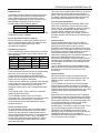
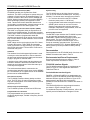
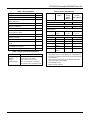
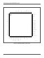
1
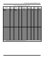
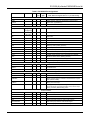
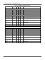
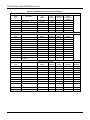
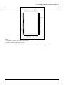
FE100/200(-M) eXtended FAXENGINE Device Set The Conexant™ FE100/200(-M) eXtended FAXENGINE adds error diffusion, Dark Level Correction (DLC), and Flash Memory Support to the suite of facsimile functions already supported by the XFE family. It is packaged in a two-device set consisting of a Conexant eXtended Facsimile Controller ® (FC100/200(-M)) and a Conexant MONOFAX Modem. This family of eXtended FAXENGINE devices provides upgrade capabilities via its hardware and software compatible controllers; the FE100/200 is backwardcompatible with other XFE device sets. Starting with the basic FE100 fax controller which includes a DRAM controller and flash memory controller, voice support (-V) can be added, along with T.6 MMR with Alternating Compression/Decompression (ACD) (-M), and full-duplex digital speakerphone support (-S). The eXtended FAXENGINE Device Set combinations are shown in Table 1. The eXtended FAXENGINE Device set, including supplied firmware, comprises a complete facsimile machine controller–needing only a power supply, scanner, printer and paper path components to complete the machine. The FAXENGINE Development System, including the FAXENGINE Evaluation System (FEES-X2) and the MC24 ROM Emulator (McFERE), provides a complete development environment. eXtended FAXENGINE Controller (FC100, FC100-M, FC200, FC200-M) The eXtended FAXENGINE Controller performs all common facsimile machine control, monitor and interface functions. The MC24™ embedded micro processor provides an 8-bit data bus, a 24-bit address bus and a direct external memory accessing capability to 16 MB. Additionally, it contains scanner, printer, keyboard, stepper motor and modem interfaces. These programmable functions and interfaces support a wide range of peripherals. Integrated 8-bit pipeline ADC, clamp, sample hold, and AGC allow minimum external scanner interface hardware. Built-in DLC and shading correction combined with two-dimensional Error Diffusion and two-dimensional edge enhancement provides state-of-the-art image processing performance in half-tone modes. The eXtended FAXENGINE Controller enables product design flexibility by virtue of its built-in peripheral and programmable hardware registers. Distinguishing Features • − − − − − − − − − − − − − − − − − − − − − − − MONOFAX Modems Seven MONOFAX modem models are available with selection depending upon the desired applications. The R144EFXL and R96DFXL/R96DFXL-CID support V.17 14400 bps and V.29 9600 bps fax transmission and reception. The RFX96V24 and RFX144V24 add integrated fax and digital answering machine functionality by providing a low bit rate voice codec that provides 24 minutes of voice storage per 4 megabits of memory. • − − ! "# $ % " &'% $ % % ( )* * * * * ( +,* ( +)* - +,. +, . .+) . ( . "" , / .* .0* . .1 2+) . ( ""# # % ! 3 % # 3 2) .( 2) * * 45$456 $ ( ""# 7 +) 8 9 & 7 +) '" 2 " ( +)/ ( +,/ 0 : ""# ;,+'# ""* . " ;);2'# ""#* 4% ;);2'# ""# 3 # 5 45$456 " 2" 3 $+ :$ $+$+ :$' The RFX144V24-S and RFX96V24-S modems support the full range of features listed above and add full-duplex speakerphone features for handsfree applications. An External Integrated Analog (XIA) front-end is added for microphone and speaker interfaces to support full-duplex digital speakerphone operation (-S). • − − • − − − − − − − − − − − − − − − − − • − − − • − − − − • • − − − − . : ( - " " % "" < , <, 3 " " . 7 2 . .( "" % / : "" % 43 - ( ' $) 1 " """ " = & ( . )$2 &'% )$2 -* "* " " - #* )$2 - % %# ( 7 ( ( 2 ! =- > " '" 2 " : :' # " " &(& "" % % " 3 - '- ) "" % + - ' # "" % '" %'- - - ( ? 00? 7 ,+ . % - 4" "" % % 4 @ "A = B6 ( )$2 - " " "" % 4 < , 4 # - 0'!# !# ) &(1 !#% # % 3 ( # =2 - # 4# =2 # " • − • − − − • − − • − • − − • • − − − • − − )% )" # % # ( )+4 % .).: .# . ..: .# $. - ! "" % ! .#$)# . .).: .#$)# "" % % % < $ , - <, & <,C + 4" ! # % ! 0'# 3 # " D 4" " ! :$/ ' 4E: ,;,:)9 "/ ' E: 9)/ &' = :)9;<; 2-" .#" :.'9 :+ - " * # -"* - % " " - 9 :)9;<; 2- . 3 -" Information provided by Conexant Systems, Inc. is believed to be accurate and reliable. However, no responsibility is assumed by Conexant for its use, nor any infringement of patents or other rights of third parties which may result from its use. No license is granted by implication or otherwise under any patent rights of Conexant other than for circuitry embodied in Conexant products. Conexant reserves the right to change circuitry at any time without notice. This document is subject to change without notice. Conexant and “What’s Next in Communications Technologies” are trademarks of Conexant Systems, Inc. Product names or services listed in this publication are for identification purposes only, and may be trademarks or registered trademarks of their respective companies. All other marks mentioned herein are the property of their respective holders. ©1999, Conexant Systems, Inc. All Rights Reserved 2 MD219 Table 1. FE100/200(-M) Family Characteristics eXtended FAXENGINE Device Set Fax Controller MONOFAX Fax Modem MH/MR/M MR/ ACD Full-Duplex Speakerphone Support Digital Answering Machine Caller ID Error Diffusion External DMA Channel R96FE100 FC100 R96DFXL 1 No No No No No R96FE100-C FC100 R96DFXL-CID 1 No No Yes No No R96FE100-V24 FC100 RFX96V24 1 No Yes Yes No No R96FE100-V24S FC100 RFX96V24-S 1 Yes Yes Yes No No R96FE100-M FC100-M R96DFXL 2 No No No No Yes R96FE100-MC FC100-M R96DFXL-CID 2 No No Yes No Yes R96FE100-MV24 FC100-M RFX96V24 2 No Yes Yes No Yes R96FE100-MV24S FC100-M RFX96V24-S 2 Yes Yes Yes No Yes R144FE100 FC100 R144EFXL 1 No No No No No R144FE100-C FC100 R144EFXL-CID 1 No No Yes No No R144FE100-V24 FC100 RFX144V24 1 No Yes Yes No No R144FE100-V24S FC100 RFX144V24-S 1 Yes Yes Yes No No R144FE100-M FC100-M R144EFXL 2 No No No No Yes R144FE100-MC FC100-M R144EFXL-CID 2 No No Yes No Yes R144FE100-MV24 FC100-M RFX144V24 2 No Yes Yes No Yes R144FE100-MV24S FC100-M RFX144V24-S 2 Yes Yes Yes No Yes R96FE200 FC200 R96DFXL 1 No No No Yes No R96FE200-C FC200 R96DFXL-CID 1 No No Yes Yes No R96FE200-V24 FC200 RFX96V24 1 No Yes Yes Yes No R96FE200-V24S FC200 RFX96V24-S 1 Yes Yes Yes Yes No R96FE200-M FC200-M R96DFXL 2 No No No Yes Yes R96FE200-MC FC200-M R96DFXL-CID 2 No No Yes Yes Yes R96FE200-MV24 FC200-M RFX96V24 2 No Yes Yes Yes Yes R96FE200-MV24S FC200-M RFX96V24-S 2 Yes Yes Yes Yes Yes R144FE200 FC200 R144EFXL 1 No No No Yes No R144FE200-C FC200 R144EFXL-CID 1 No No Yes Yes No R144FE200-V24 FC200 RFX144V24 1 No Yes Yes Yes No R144FE200-V24S FC200 RFX144V24-S 1 Yes Yes Yes Yes No R144FE200-M FC200-M R144EFXL 2 No No No Yes Yes R144FE200-MC FC200-M R144EFXL-CID 2 No No Yes Yes Yes R144FE200-MV24 FC200-M RFX144V24 2 No Yes Yes Yes Yes R144FE200-MV24S FC200-M RFX144V24-S 2 Yes Yes Yes Yes Yes Notes: 1. MH/MR compression and decompression. 2. MH/MR/MMR and Alternating Compression Decompression for Page memory. MD219 3 FAXENGINE Firmware The FAXENGINE firmware includes a complete software package–core code and application code–for the development of a customized facsimile machine. The following features are supported by the firmware: • • • • • • • • • • • • • • • • • • ) '" " ! -" 3 450 " 45 $+ " " 456 +* ) "$" "# " " ' # ) : ( "* - # % 4($+( 2 # 4 " ' # 2 )3 '7 '7. # : ( 2 . ! '7. # : :' # 6'- 2 4 % ;);2 ;,+ # : ""# "" % - 7$: ( 2" 2 Core Code. The Core Code provides the functions with close functional proximity to the FE100/200(-M) hardware. The Core Code is provided in object code form ready for linking to developer-provided application program object code. The Core Code is highly structured for maximum application flexibility with minimum overhead. Application Code. The Application Code “builds” an example fax machine using the FE100/200(-M) device set in the FEES-X2 environment. The Application Code is provided in source code form and serves as basis for the developer’s application. FE100/200 eXtended FAXENGINE Development System The Conexant FAXENGINE Evaluation System (FEESX2) and MC24 FERE (Fax Engine ROM Emulator) provides demonstration, prototype development, and evaluation capabilities to facsimile machine developers using the FE100/200 eXtended FAXENGINE Device Set. The FEES-X2 offers flexibility for visibility and access. It consists with the Modem Evaluation Board, Data Access Arrangement (DAA), sockets for programmable parts, and connectors for an emulator and all fax machine peripherals. The ROM Emulator (MC24 FERE) is a PC-based firmware development/debugging environment with breakpoint and trace capability for developers. Hardware Description The FE100/200 system-level functional interface is shown in Figure 1. Note: 4 eXtended Facsimile Controller (FC100/200) The FC100/200 contains an internal 8-bit microprocessor with a 16MB external address space and dedicated circuitry optimized for facsimile image processing, image data compression/decompression and for facsimile machine control and monitoring. Microprocessor The microprocessor is an enhanced MC24 central processing unit (CPU). This CPU provides fast instruction execution and memory efficient input/output bit manipulation. The CPU connects to other internal FC100/200 functions over internal address, data and dedicated control buses. These buses are routed outside the FC100/200 for external memory access. External Bus Control Address, data, control, status, interrupt, and decoded chip select signals support connection to external ROM, external RAM, and optional DRAM and peripheral devices. Dedicated internal DMA logic is included for scanner, printer and T.4 access of internal and/or external RAM. Six internal DMA channels support scanner, printer and T.4 access of the external shading and line buffer RAM. A programmable DMA channel is available to support T.4/T.6 access to external page memory. External RAM and ROM FC100/200 can use 3 MB of ROM and up to 1 MB of SRAM. ROM stores all the FAXENGINE program object code and SRAM is used by the FAXENGINE CPU, shading RAM, and line buffer RAM. Independently programmable SRAM and ROM wait states from 0 to 3 are supported. SRAM sizes may be 8, 32, 64K and 1 MB. Chip Selects Various chip selects (CS) are provided by the FC100/200 such as ROMCSn, CS0n for SRAM, CS1n for external peripherals, MCSn for modem, and optional general purpose chip selects CS[4:2]n and CS5n. Interrupt Signals Up to three external interrupts are provided. IRQ8 (GPIO16) is an active high level sensitive interrupt and IRQ9n (GPIO18) is an active low-level sensitive interrupt. MIRQn is dedicated to the modem. Scanner and Printer Motor Control Eight outputs are provided to external current drivers: four to the scanner motor and four to the printer motor. The printer and scanner motor outputs can be programmed as GPOs for applications using a single motor or plain paper printers. The suffix n indicates an active low signal. MD219 T.4/T.6 Compressor/Decompressor The FC100/200 implements MH/MR image data compression and decompression per ITU-T Recommendation T.4 in hardware. The FC100/200-M also provides MMR compression and decompression per ITU-T Recommendation T.6 in dedicated hardware. Compression and decompression can be alternated on a line-by-line basis in the FC100/200-M with the support of FE100/200-M Firmware. MD219 5 Scanner Controls & Sensors Scanner Video Preprocessing Sync Ports (2) (SSIF) START CLK2 CLK1 CLK1n VIDCTL[1:0] VIN +VREF -VREF RIN SYSCLK MIRQn MCSn eXtended Facsimile Controller FC100/200(M) A[23:0] D[7:0] RDn WRn ROMCSn SSCLK[2:1]* SSTXD[2:1]* SSRXD[2:1]* SSSTAT[2:1]* SPKR A[4:0] D[7:0] RDn WRn Sync/Async Serial Port SASIF FRDn* FRWn* FCLE* FCS[0:2] DEBUGn VDD VDRAM VBAT SASCLK* SASTXD* SASRXD* MIC SPKR TXA RXDAT TXDAT RMODE TMODE CLKIN SLEEPn CAS[0,1]n, RASn, DWRn CS[5:0]n* GPIO MONOFAX Facsimile Modem GPIO WRPROTn General Purpose I/O Analog Switch CS3n, CS4n** D[7:0 ] RIN SM[3:0]* RTC Crystal TXOUT Speaker Microphone Circuit SPKRHi SPKRLo XIN XOUT PM[3:0]* Line Interface RXA TONE/ALTTONE TSTCLK REGDMA WAITn SYNC PWRDWNn STRB[3:0] STRBPO L THA D I PD A T PCLK PLA T TXA1 Printer & Scanner Motor Drivers RXIN TXA2 Printer Data Control & Sensors Telephone Line TEST BATRSTn RESETn External Bus Operator Panel, Keypad, LEDs & LCD OPO[7:0]* OPI[3:0]* LEDCTL* LCDCS* XIA GPIO DRAM (option) Flash Memory Notes: * Alternative GPO, GPI or GPIO lines Speakerphone only VSS Voice or speakerphone MD 219F-1 Figure 1. FE100/200 Functional Interconnect Diagram 6 MD219 DRAM Controller The DRAM controller supports memory devices of the sizes, number of bits and access speeds tabulated below. DRAM memory space is divided into three blocks thus, if 4 MB chips are used, a maximum of 8 MB of DRAM is supported. Each block has a programmable size and starting address. Addressing Size 4 MB, 1MB, 512K, 256K No. of Bits 8, 4, 1 Access Speed (ns) 60 to 150 DRAM controller provides battery backup refresh using DRAM battery power (VDRAM). Bi-Level Resolution Conversion (-M only) Bi-level expansion (to 200%) and reduction (down to 33%) can be performed on either the scanner bi-level data or the bi-level data output by the T4/T6 decompression hardware. Flash Memory Controller The FC100/200(-M) includes a flash memory controller that supports the following types of flash memory and their equivalents: Vendor Model Size (K) Type AMD Am29F040 512 NOR Intel 28F400BL 512 NOR 512 Serial NAND Toshiba TC58A040F Samsung KM29N040/080-150 NAND Thermal Printer Control The thermal printer interface consists of programmable data, latch, clock, and up to four strobe signals. Programmable timing supports traditional thermal printers, as well as latchless and two-clock split mode printers, and line lengths to 4096 pixels. From one to four strobes are generated, with the length of the strobe cycle (line time) and strobe pulse width programmable. Line times from 5 to 40 ms are supported. A strap input to the FC100/200 sets strobe polarity. Three signals (PDAT, PCLK, and PLAT) control the transfer of data to the printer. The FC100/200 includes a 6-bit A/D converter (conversion rate < 80 ms full scale) to monitor the head temperature of the thermal printer. Two external terminating resistors are determined by the specific printhead selected. Scanner and Video Control Six programmable control and timing signals support common CCD and CIS scanners. The video control function provides signals for controlling the scanner and for processing its video output. Four programmable control signals (START, CLK1, CLK1n, and CLK2) provide timing related to line and pixel timing. These are programmable with regard to start time, relative delay and pulse width. MD219 Two video control output signals (VIDCTL[1:0]) provide digital control for external signal pre-processing circuitry. These signals provide a per pixel period, or per line period, timing with programmable positive-going and negative-going transitions for each signal. Scanner Pipeline A/D Interface An internal 8-bit pipeline A/D converter (PADC) and ADC clock are provided. The A/D reference inputs (Vref+ and Vref–) are available for control by external circuits. A programmable ADC sample position is provided. Built-in Automatic Gain Control (AGC) amplifier and Input Analog (IA) clamping circuits are provided. External video circuits can be tailored by the developer. Video Processing The FC100/200 supports DLC and two modes of shading correction for scanner data non-uniformity’s arising from uneven sensor output or uneven illumination. Correction may be provided to an 8-pixel group at a time or, separately to each pixel. Less than 1 K of RAM is required to support shading correction. A Digital Adaptive Halftone image processing is supported. A 2-Dimensional error diffusion algorithm as well as a 2-D Edge Enhancement control are performed in the hardware. Dynamic background and contrast control is provided for text images. Multi-level horizontal B4 to A4 reduction is also provided for the scanner data. The FC100/200 includes an optional external image data processing port (multiplexed with GPIO) to allow the developer to access scan data prior to video processing. Operator Interface Operator interface functions are supported by the operator output bus OPO[7:0] the operator input bus OPI[3:0], and two control outputs (LEDCTL and LCDCS). The FC100/200 can directly drive a 32-key keypad. External blocking diodes are required to isolate the keyboard strobe lines from the LEDs, as the LEDs and keyboard strobe signals use the same lines. Up to 8x15 keyboard array can be supportable with external circuitry. Eight LEDs can be driven directly by the FC100/200. The keyboard strobes are shared with the LED drivers. An LED control signal is provided to disable the LEDs during keyboard strobing. The FC100/200 offsets LED turn on/off times thereby preventing power supply overload when all indicators are activated simultaneously. The LEDCTL signal can supply 12 ma. Typical LCD display modules are driven by the FC100/200. The FC100/200 drives the 4-bit bus (OPO[3:0]) and two separate control lines (OPO4 and LCDCS) for LCD support. (For example, the FAXENGINE Development System FEES-X2 uses a 2line, 20 character per line display.) 7 Synchronous Serial Interface (SSIF) System Timing FE100/200 provides two Synchronous Serial Interfaces. The SSIF is configured to operate either as a Master or Slave interface (bi-directional Clock). The interface consists of three lines: SSTXD, SSRXD and SSCLK. Optional control signals for request (SSREQ) and acknowledge (SSACK) are supported in slave mode. Transmit and receive data shift direction and clock polarity is programmable. Internal interrupt can be generated when the receive data register is full. The FC100/200 derives its timing from the modem clock or from an external oscillator (max. frequency = 20 MHz). Two internal timer interrupts are provided: Synchronous Asynchronous Serial Interface (SASIF) The SASIF is configurable either as Synchronous or Asynchronous Serial Interface. This interface consists of three lines: SASTXD, SASRXD and clock (SASCLK). The SASIF includes a programmable baud rate generator and produces an 8X driving clock for internal logic. Receive data is double-buffered to ease received timing restrictions. SASIF status can be read anytime by the CPU. Status includes: IRQ source (TXD or RXD) and operation mode (synchronous or asynchronous). The CPU can also control and monitor TXD and SCLK. RXD can be monitored at any time. Autobaud The autobaud circuit with supporting firmware is used to analyze a serial data stream in order to determine the baud rate and data structure (parity and character length) to program an external UART. A precision timer, shift register and edge detector are included to determine the width of the start bit and to sample the serial data stream. Serial data rates up to 115.2 kbps are supported. The serial transmitted data is connected to the precision timer and shift register inputs via the SERINP pin. The SEROUT pin is a gated version of the SERINP pin that can be enabled/disabled. Real-Time Clock (RTC) The FC100/200 includes a battery backup real-time clock. The RTC life is 32 years; its functions include leap year compensation. A 32.768 kHz watch crystal is required by the RTC. General Purpose Inputs/Outputs The FC100/200 provides 20 GPIO and 8 GPO lines. Programmable Tone Generator • A 1 ms timer derived from the RTC oscillator timebase (exact period = 1.00708 ms). • A programmable mechanical subsystem interrupt (MSINT) which serves as a source for motor stepping interrupts and/or scanner and printer interrupts. Independent, programmable, scan and print line times are supported. Reset and Power Control The BATRSTn input initializes the FC100/200 at poweron. An externally generated power-down input, PWRDWNn, controls switching between primary and battery power. The open drain RESETn I/O pin provides a reset output to external circuits, or can accept an externally generated reset. The external reset will not reset the RTC. Separate DRAM and RTC battery power inputs are provided for battery-backup functions. Documentation Documentation for the FE100/200 family of devices and MONOFAX modems are listed in Table 2. Environmental and Power Requirements Environmental specifications are shown in Table 3. Power requirements are shown in Table 4. FC100/200 Interface Signals The FC100/200 hardware signal pin assignments are shown in Figure 2. These signals are described in Table 5and Table 6. Facsimile Modem Interface Signals R96DFXL (-CID)and R144EFXL pin assignments are shown in Figure 3. RFX96V24(-S) and RFX144V24(-S) hardware interface signals are shown in Figure 4. Pin assignments for the 28-pin XIA used with the RFX96V12-S and RFX144V12-S modems are shown in Figure 5. The FE100/200(-M) device set package dimensions are shown in Figure 6 though Figure 8. For additional information on these devices, refer to the specific product’s Data Sheet or Designer’s Guide. Two programmable tone generators each provide single tone digital output, variable in frequency from 20 to 4000 Hz. 8 MD219 Table 4. Power Requirements Table 2. Documentation Document Order No. R96DFXL MONOFAX Modem Data Sheet Device Voltage (Note 1) MD92 R144EFXL MONOFAX Modem Data Sheet MD90 RFX144V24-S and RFX96V24-S MONOFAX Modems Data Sheet MD141 9600 bps MONOFAX Modem Designer’s Guide 820 9600 bps MONOFAX Modem Designer’s Guide– Addendum for R96DFXL 820A FC100/200 Primary Power +5 VDC +5%/-10% 895 RFX144V24-S and RFX96V24-S MONOFAX Modems Designer’s Guide 1070 MC24 Megacell CPU Programmer’s Guide 415 eXtended Facsimile Controller (FC100/200) Hardware Description 1171 - Maximum Current @ 0°C (Note 3) - 65 ma 70 ma 67 ma 72 ma - - 17 µA 5 µA 20 µA 5.5 µA 55 ma FE100/200-M Primary Power +5 VDC +5%/-10% R144EFXL MONOFAX Modem Designer’s Guide Typical Current @25°C (Note 3) FC100/200-M Battery Power and RTC (Note 2) +5 VDC +3 VDC MONOFAX Modems R96DFXL +5 VDC ±5% 50 ma 1139 R144EFXL +5 VDC ±5% 54 ma 60 ma FAXENGINE Evaluation System (FEES-X2) User’s Manual 1066 RFX96V24 +5 VDC ±5% 100/2 ma 119/2.5 ma RFX96V24-S 149/2.8 ma 1016 +5 VDC ±5% (Note 4) 124/2.15 ma MC24 FAXENGINE ROM Emulator System (MC24FERE) User’s Manual RFX144V24 +5 VDC ±5% 100/2 ma 119/2.5 ma MC24 Megacell CPU Programming Manual 415 RFX144V24-S +5 VDC ±5% (Note 4) 124/2.15 ma 149/2.8 ma eXtended FAXENGINE Firmware Description Table 3. Environmental Specifications Notes: Parameter Specification 1. Temperature Operating Storage Relative Humidity MD219 0°C to 70°C (32°F to 158°F) -40°C to 80°C (-40°F to 176°F) 90% non-condensing, or a wet bulb temperature to 35°C, whichever is less. 2. 3. 4. Input voltage ripple ≤0.1 volts peak-to-peak. The amplitude of any frequency between 20 and 150 kHz must be less than 500 microvolts peak. Real-Time Clock (RTC) battery power measurements made with a 32.768 kHz crystal oscillator. Normal/Standby current. Modem and XIA combined. 9 PM2/GPO2 PM3/GPO3 MCSn ROMCSn TONE PM0/GPO0 PM1/GPO1 VDDi CS1n VSSo RESETn TSTCLK DEBUGn RDn WRn SYNC WAITn REGDMA D5 D6 D7 MIRQn VSSi SYSCLK D3 VDDo D4 VDRAM RASn CAS0n CAS1n WRPROTn DWRn VSSo GPIO20/ALTTONE SM0/GPO4 SM1/GPO5 SM2/GPO6 SM3/GPO7 VDDi START CLK1 CLK1n CLK2 FCS2n/VIDCTL1 FCS1n/VIDCTL0 VSSi GPIO0 GPIO1/SASTXD GPIO2/SASRXD GPIO3/SASCLK GPIO4/CPCIN GPIO5/SSCLK2 VSSo GPIO6/SSTXD2 GPIO7/SSRXD2 GPIO8/FWRn GPIO9/FRDn GPIO10/SSSTAT2 GPIO11/BE/SERINP VDDo GPIO12/CS2n GPIO13/CS3n GPIO14/CS4n GPIO15/CS5n GPIO16/IRQ8 GPIO17 GPIO18/IRQ9n GPIO19/RDY/SEROUT VIN ADXG ADGA ADVA +VREF ADGD STRBPOL OPO7/GPO15 STRB0 THAD1 -VREF/CLREF VDDi STRB3 STRB2 STRB1 XOUT BATRSTn PWRDWNn VBAT VSSi VSSi PCLK PDAT PLAT TEST XIN A3 A2 A1 A0 VSSo CS0n A6 VSSo A5 A4 OPI1/GPIO22/SSTAT1 OPI0/GPIO21/SSRXD1 VSSi LCDCS/GPIO17 LEDCTL/GPIO16 A11 A10 A9 A8 A7 OPI3/GPIO24 OPI2/GPIO23/SSCLK1 A13 A12 VDDo OPO3/GPO11 OPO2/GPO10/RINGER VSSo OPO1/GPO9/PMPWRCTRL OPO0/GPO8/SMPWRCTRL VDDi A17 A16 A15 A14 108 107 106 105 104 103 102 101 100 99 98 97 96 95 94 93 92 91 90 89 88 87 86 85 84 83 82 81 80 79 78 77 76 75 74 73 OPO6/GPO14 OPO5/GPO13 VDDo OPO4/GPO12/SSTXD1 A20 A19 A18 VSSo 1 2 3 4 5 6 7 8 9 10 11 12 13 14 15 16 17 18 19 20 21 22 23 24 25 26 27 28 29 30 31 32 33 34 35 36 37 38 39 40 41 42 43 44 45 46 47 48 49 50 51 52 53 54 55 56 57 58 59 60 61 62 63 64 65 66 67 68 69 70 71 72 A23 A22 A21 144 143 142 141 140 139 138 137 136 135 134 133 132 131 130 129 128 127 126 125 124 123 122 121 120 119 118 117 116 115 114 113 112 111 110 109 D0 D1 D2 MD162R1F2 Figure 2. FC100/200 Pin Signals - 144-Pin TQFP 10 MD219 Table 5. FC100/200 Pin Assignments Pin Name Pin No. I/O Input Type Output Type MIRQn 135 I HU SYSCLK 133 I H -- TSTCLK 130 O -- 123XT Pin Description Note: Active low signals have an “n” pin name ending. CPU Control Interface -Modem interrupt, active low. (Hysteresis In, Internal Pullup.) System clock. (Hysteresis In.) Test clock. Bus Control Interface 123XT Address bus (24-bit). A[23:0] [1:6][8:13] [15:20][22:27] O TU D[7:0] [136:139] [141:144] I/O TU 123XT Data bus (8-bit). RDn 128 O -- 123XT Read strobe. WRn 127 O -- 123XT Write strobe. ROMCSn 120 O -- 123XT ROM chip select. CS1n 122 O -- 123XT I/O chip select. CS0n 57 O -- 123XT SRAM chip select. (Battery powered.) MCSn 121 O -- 123XT Modem chip select. SYNC 126 O -- 123XT Indicates CPU op code fetch cycle (active high). REGDMA 124 O -- 123XT Indicates REGSEL cycle and DMA cycle. WAITn 125 O -- 123XT Indicates current TSTCLK cycle is a wait state or a halt state. RASn 113 O - 123XT DRAM row address select. (Battery powered.) [111:112] O - 123XT DRAM column address select. (Battery powered.) DWRn 109 O - 123XT DRAM write. (Battery powered.) DEBUGn 129 I RESETn 131 I/O HU 2XO TEST 58 I C -- XIN 59 Battery Power Control and Reset Logic I OSC -Crystal oscillator input pin. XOUT 60 O -- OSC PWRDWNn 62 I H -- BATRSTn 61 I H -- WRPROTn 110 O -- 1XC START 101 O -- 2XS Scanner shift gate control. CLK1 100 O -- 2XS Scanner clock. CLK1n 99 O -- 2XS Scanner clock-inverted. CLK2 98 O -- 2XS Scanner reset gate control (or clock for CIS scanner). FCS1n/VIDCTL0 96 O -- 2XT Flash memory chip select or Video Control signal. FCS2n/VIDCTL1 97 O -- 2XT Flash memory chip select or Video Control signal. CAS[1:0]n Prime Power Reset Logic and Test HU -External non-maskable input (NMI). FC100/200 Reset. Sets Test mode (battery powered). Crystal oscillator output pin. Used by external system to indicate--to FC100/200--loss of prime power. (Results in NMI). Battery power reset input. (Battery powered.) Write protect during loss of VDD power. NOTE: The functional logic is powered by battery power, but the output drive is powered by DRAM battery power. Scanner Interface MD219 11 Table 5. FC100/200 Pin Assignments (Cont’d) Pin Name Pin No. I/O Input Type PCLK/DMAACK 29 O -- PDAT 30 O -- 2XP Serial printing data (to TPH). TPH data latch. PLAT Pin Description Printer Interface 3XC Thermal Print Head (TPH) clock or external DMAACK. 31 O -- 3XP [33:36] O -- 1XP STRBPOL/DMAREQ 37 I C -- OPO[5]/GPO[13] 40 O -- OPO[6]/ GPO[14] 39 O -- 2XL Keyboard / LED strobe [ 6 ] or GPO[14] OPO[7]/GPO[15] 38 O -- 2XL Keyboard / LED strobe [ 7 ] or GPO[15] OPI[0]/ GPIO[21]/ SSRXD1 52 I/O HU 2XC (Pullup, Hysteresis In) Keyboard return [ 0 ] or GPIO[21] or SSRXD1 ( for SSIF1) OPI[1]/ GPIO[22]/ SSSTAT1 51 I/O HU 2XC (Pullup, Hysteresis In) Keyboard return [ 1 ] or GPIO[22] or SSSTAT1 (for SSIF1) OPI[2]/GPIO[23]/ SSCLK1 50 I/O HU 2XC (Pullup, Hysteresis In) Keyboard return [ 2 ] or GPIO[23] or SSCLK1 (for SSIF1) OPI[3]/GPIO[24] 49 I/O HU 2XC (Pullup, Hysteresis In) Keyboard return [ 3 ] or GPIO[24] LEDCTL 55 O -- 4XC Indicates outputs OPO[7:0] are for LEDs. LCDCS 54 O -- 1XC LCD chip select. GPIO[0] 94 I/O H STRB[3:0] 12 Output Type Strobe signals for the TPH. Sets strobe polarity, active high/low. Scanner Interface 2XL Keyboard / LED strobe [ 5 ] or GPO[13] General Purpose I/O 2XC (Hysteresis In) GPIO[0]. GPIO[1]/SASTXD 93 I/O H 2XC (Hysteresis In) GPIO[1] or SASTXD (for SASIF). GPIO[2]/SASRXD 92 I/O H 2XC (Hysteresis In) GPIO[2] or SASRXD (for SASIF). GPIO[3]/SASCLK 91 I/O H 2XC (Hysteresis In) GPIO[3] or SASCLK (for SASIF) . GPIO[4]/CPCIN 90 I/O H 2XC (Hysteresis In) GPIO[4] or Calling Party Control Input GPIO[5]/SSCLK2 89 I/O H 2XC (Hysteresis In) GPIO[5] or SSCLK2 (for SSIF2). GPIO[6]/SSTXD2 87 I/O H 2XC (Hysteresis In) GPIO[6] or SSTXD2 (for SSIF2). GPIO[7]/SSRXD2 86 I/O H 2XC (Hysteresis In) GPIO[7] or SSRXD2 (for SSIF2) . GPIO[8]/FWRn 85 I/O H 2XC (Hysteresis In) GPIO[8] or flash write enable signal for NAND-type flash memory. GPIO[9]/FRDn 84 I/O H 2XC (Hysteresis In) GPIO[9] or flash read enable signal for NAND-type flash memory. GPIO[10]/ SSSTAT2 83 I/O H 2XC (Hysteresis In) GPIO[10] or SSSTAT2 (for SSIF2). GPIO[11]/BE/ SERINP 82 I/O H 1XC (Hysteresis In) GPIO[11] or bus enable or serial port data input for autobaud detection. MD219 Table 5. FC100/200 Pin Assignments (Cont’d) Pin Name Pin No. I/O Input Type Output Type Pin Description GPIO[12]/CS[2]n 80 I/O General Purpose I/O (Cont’d) H 2XC (Hysteresis In) GPIO[12] or I/O chip select [2]. GPIO[13]/CS[3]n 79 I/O H 2XC (Hysteresis In) GPIO[13]or I/O chip select [3]. GPIO[14]/CS[4]n 78 I/O H 2XC (Hysteresis In) GPIO[14] or I/O chip select [4]. GPIO[15]/CS[5]n 77 I/O H 2XC (Hysteresis In) GPIO[15] or I/O chip select [5]. GPIO[16]/IRQ[8] 76 I/O H 1XC (Hysteresis In) GPIO[16] or external interrupt 8. GPIO[17] 75 I/O H 1XC (Hysteresis In) GPIO[17] GPIO[18]/IRQ[9]n 74 I/O H 1XC (Hysteresis In) GPIO[18] or external interrupt 9. GPIO[19]/RDY/ SEROUT 73 I/O H 1XC (Hysteresis In) GPIO[19] or ready signal or Serial port data output for autobaud detection. GPIO[20]/ ALTTONE 107 I/O H 1XC (Hysteresis In) GPIO[20] or ALTTONE. SM[3:0]/GPO[7:4] [103:106] O -- PM[3:0]/GPO[3:0] Miscellaneous 1XC Programmable: scan motor control pins or GPO pins. [115:118] O -- 1XC Programmable: print motor control pins or GPO pins. TONE 119 O -- 1XC Tone output signal. -Vref/CLREF 66 I ADXG 68 I ADGA 69 VADG ADVA 70 VADV A/D Analog Power ADGD 72 VADG A/D Digital Ground +Vref 71 I +VR VIN 67 I VA -- Analog Video A/D input. THADI 65 I TA -- Analog Thermal A/D input. VSS(12) 7, 21, 28, 45, 53, 56, 64, 88, 95, 108, 132, 134 VDD (8) 14, 32, 41, 48, 81, 102, 123, 140 Power, Reference Voltages, Ground -VR -Negative Reference Voltage for Video A/D or Reference Voltage for the Clamp Circuit VXG -- A/D Internal GND. (NOTE: This pin requires an external 0.22µF decoupling capacitor to ADGA.) A/D Analog Ground Positive Reference Voltage for Video A/D. Power and Ground Digital Ground Digital Power VBAT 63 Battery Power VDRAM 114 DRAM Battery Power MD219 13 Table 6. FC100/200 Hardware Signal Characteristics Input Signal Characteristics Input Type Description VIL (V max) VIH (V min) Hysteresis (V min) Pullup Resistance (K ohm) -- C CMOS Input 0.3*VDD 0.7*VDD -- H Hysteresis 0.3*VDD 0.6*VDD 1.0 -- Hysteresis/Pullup 0.3*VDD 0.6*VDD 1.0 35–150 0.8 2.0 -- -- 0.8 2.0 -- 35-150 0.3*VDD 0.7*VDD -- -Abs. Max. (V max) HU T TTL Input TU TTL/Pullup OSC CMOS Input Absolute Input Range = 0.5 to VDD+0.5 Input Type Description Operating (V min) Operating (V max) Abs. Max. (V min) 0.2*VDD 0.8*VDD –0.5 VDD+0.5 -VR +VR -0.5 VADV + 0.5 TA Thermal Head Analog Input VA Video Analog In +VR Video A/D +Vref 0.8 3.3 -0.5 VADV + 0.5 -VR Video A/D -Vref -0.2 2.0 -0.5 VADV + 0.5 VXG Video Internal Ground -- -- -- -- VADV Video A/D Power VDD-0.1 VDD + 0.1 -0.5 7.0 VADG Video A/D GND -0.1 0.1 -0.5 0.5 VDD Digital Power 4.5 5.25 –0.5 7.0 GND Digital Ground 0 0 0 0 Battery Power for DRAM 2.25 5.25 –0.5 7.0 Battery Power for RTC/SRAM 2.25 5.25 –0.5 7.0 VDRAM VBAT Output Signal Characteristics Output Type VOL (V max) IOL (ma max) VOH (V min) IOH (ma max) CMOS Output (1X) 0.4 1.6 VDD–1.5 1.6 50 High Capacitance Driver 0.4 1.6 VDD–1.5 1.6 200 2XC CMOS Output (2X) 0.4 3.5 VDD–1.5 3.5 50 2XT TTL Output (2X) 0.4 4 2.4 4 50 2XS CMOS Output (2X) 0.4 3.5 VDD–1.5 1.5 3.5 15 50 50 1XC 1XP, 2XP CL (pF max) 2XL LED Driver 0.7 10 VDD–1.5 3.5 100 2XO CMOS Output, Open Drain 0.4 3.5 N/A N/A 50 3XC CMOS Output (3X) 0.4 6 VDD–1.5 6 50 3XP High Capacitance Driver (3X) 0.4 6 VDD–1.5 6 700 4XC CMOS Output (4X) 0.4 12 VDD–1.0 12 50 0.4 1.6/4/6 2.4 1.6/4/6 50 123XT 14 Description 1/2/3X (Tristate) Output MD219 RAMPIN NC NC 0VA +5VD2 0VD1 SWGAINI ECLKIN1 SYNCIN1 NC NC NC NC NC NC DAIN 0VA 0VD2 DAOUT ADIN EYEX EYECLK EYECLKX EYESYNC DCLK 0VD2 80 79 78 77 76 75 74 73 72 71 70 69 68 67 66 65 64 63 62 61 60 59 58 57 56 55 54 53 52 51 0VD2 TXD CTSn 0VD2 GP17 GP16 SYNCIN2 (G2XCLK) DCLKI (IRQ2n) +5VD1 YCLK XCLK XTLO XTLI PORIn 0VD2 EN85n RTSn GP11 SEE NOTE 1 GP13 RS0 RS1 RS2 RS3 RS4 READn CSn WRITEn IRQn NC ADOUT BYPASS RCVI TXLOSS3 TXLOSS2 TXLOSS1 NC NC 0VA TXOUT RXIN +5VA 0VA AGD AOUT 0VD1 0VD2 0VA 1 2 3 4 5 6 7 8 9 10 11 12 13 14 15 16 17 18 19 20 21 22 23 24 25 26 27 28 29 30 31 32 33 34 35 36 37 38 39 40 41 42 43 44 45 46 47 48 49 50 GP03 GP04 GP05 GP06 GP07 0VD2 0VD2 D7 D6 D5 D4 D3 D2 D1 D0 100 99 98 97 96 95 94 93 92 91 90 89 88 87 86 85 84 83 82 81 GP02 SWGAINO RCVO 0VD2 RLSDn RXD GP19 GP20 0VD2 GP21 EYEY MD125F3 MDMPA100F Notes: 1. For R96DFXL, connect pin 62 to +5VD1 or leave, open (nc); For R144EFXL, connect pin 62 to +5VD1. 2. Names in parentheses apply to R144EFXL only. Figure 3. R96DFXL and R144EFXL Facsimile Modem Pin Assignments MD219 15 ~WRITE DGND1 RXOUT RMODE TSTROBE TRESET DGNDA1 NC TMODE TXDAT AVDD ~TALK AGND1 TXA1 TXA2 NC NC NC NC VAA1 ~SLEEP AGND2 RIN VC VREF NC NC DGNDA3 DGNDA2 80 79 78 77 76 75 74 73 72 71 70 69 68 67 66 65 64 63 62 61 60 59 58 57 56 55 54 53 52 51 DGND3 SR3IN ~IRQ2 VDD3 YCLK XCLK XTLO XTLI ~RESET GPO0 GPO1 GPO2 ~IRQ1 ~CTS DGND2 GPO3 GPO4 GPO5 GPO6 GPO7 GPI7/RINGD GPI6 VDD2 GPI5 GPI4 GPI3 GPI2 ~READ ~CS NC SPKR VAA2 ~OH ~POR CLKIN NC IACLK VDD1 D7 D6 D5 D4 D3 D2 D1 D0 1 2 3 4 5 6 7 8 9 10 11 12 13 14 15 16 17 18 19 20 21 22 23 24 25 26 27 28 29 30 31 32 33 34 35 36 37 38 39 40 41 42 43 44 45 46 47 48 49 50 RS4 RS3 RS2 RS1 RS0 100 99 98 97 96 95 94 93 92 91 90 89 88 87 86 85 84 83 82 81 RXD TXD GPI1 DGND5 ~RTS GPI0 ~EN85 DCLK ~RLSD NC SR4OUT EYEXY SR1IO SA1CLK IA1CLK EYECLK EYESYNC SR3OUT SR4IN DGND4 MD162F4 Pin Sigs 100F NC RXDAT RMODE RRESET 25 24 23 22 21 20 19 VREF VC RIN A0VR ~SLEEP P5VT NC TMODE TXDAT P5VD NC A0VT TXA1 TXA2 12 13 14 15 16 17 18 RSTROBE TSTROBE TRESET 5 6 7 8 9 10 11 4 3 2 1 28 27 26 CLKIN ~POR NC DGND P5VR NC NC Figure 4. RFX96V24 (-S) and RFX144V24 (-S) Facsimile Modem Pin Assignments MD162F4 Pin Sigs 28L Figure 5. 28-Pin XIA Pin Signals 16 MD219 Software Description Supplied Firmware FAXENGINE firmware supplied with the FE100/200 consists of Core Code and Application Code. The Application Code, in conjunction with Core Code and FC100/200 (when connected to scanner and printer peripherals) provides a complete facsimile machine. The Core Code (subdivided as Macro and Primitive functions) is supplied as object code, whereas the Application Code (to complete a fax machine) is supplied as assembly-level source code. • Printer paper handling (eject and cut) • Copy page • Setup controls for the facsimile machine (date and time, header, transmit level) • Call progress controls with parameter tables to allow modification for PTT requirements in different countries • T.30 control by generating frame content and sequence used during a T.30 negotiation • Fax/Voice discrimination with external answering machine interface Core Code Conditional Assembly The Core Code includes proprietary primitives and macros in object code form located in ROM at the top of the FAXENGINE processor address space. These Core Code primitives and macros provide the following functions: Other supported functions included in the final object code (when the appropriate conditional assembly switches are enabled) are as follows: • Error Correction Mode (ECM) • Modem control • Flash memory (Voice storage) • T.30 framing and control • • T.4 MH, MR and MMR control for FC100/200 and FC100/200-M compression/decompression hardware. Supports Line times of 5 ms per line. Page Memory support that includes broadcast/delayed capabilities and receiving to memory • Resolution conversion • Multi-level and bi-level B4 to A4 reduction • Send and receive a page • Digital answering machine support • Real-time multitasking executive for scheduling high priority (interrupt-driven) tasks and servicing low priority (background) tasks • Full duplex digital speakerphone The Core Code subroutines are organized in a modular layered structure that allows for replacement of any of these subroutines by OEM-written custom subroutines. The supplied firmware allows conditional inclusion of the following items, some of which automatically add other options, as noted: • FC100/200 type (MMR and ACD option.) • Modem type • ECM RAM (and size of Comm Buffer) • Speakerphone • UART interface for debug The Application Code provides source assembly code for a complete facsimile machine application. The Application Code links to the Core Code functions to control the FAXENGINE peripheral functions. The Application Code performs customized functions to provide flexibility to enable the following: • Scan image processing enabled/disabled • Line ORing enabled/disabled • Call progress country • Language for operator interface • Scanner and printer control • • Operator panel control (Keypad, LED, LCD, Beeper) Fax mechanism. (Specifies parameter ranges for scanning and printing timing, scanner and printer width, shading correction and edge enhancement threshold value.) • Scan document handling (pull-in and eject) Core Code routines are organized in a library and the Core Code linkage routine optimizes ROM space code by preventing code duplication when Core Code routines are unused or replaced by Developer routines. Application Code MD219 17 See detail A D CHAM (4X) D1 D2 E1 E E1 E2 PIN 1 REF e b TOP VIEW SIDE VIEW Dim. A A1 A2 D D1 D2 E E1 E2 A L A2 L1 e c DETAIL A L 0.0945 MAX 0.35 0.05 2.0 REF 0.0020 23.45 22.95 20.0 REF 0.9035 0.7421 REF 0.6673 0.6870 0.5512 REF 12.35 REF 1.03 0.73 1.6 REF 0.9232 0.7874 REF 18.85 REF 17.45 16.95 14.0 REF 0.0138 0.0787 REF 0.4862 REF 0.0287 0.0406 0.0630 REF 0.65 BSC 0.0256 BSC b 0.25 0.45 0.0098 0.0177 c 0.19 0.13 0.10 MAX 0.0051 0.0075 Coplanarity A1 Inches* Max. Min. Millimeters Max. Min. 2.4 MAX 0.004 MAX Ref: 100-PIN PQFP (GP00-D234) L1 * Metric values (millimeters) should be used for PCB layout. English values (inches) are converted from metric values and may include round-off errors. PD-PQFP-100 (040695) Figure 6. 100-Pin PQFP Dimensions 18 MD219 D D1 D2 PIN 1 REF D D1 D1 D2 e b DETAIL A Dim. A A1 D1 A2 D D1 D2 L A A2 Inches* Max. Min. Millimeters Max. Min. 1.6 MAX 0.15 0.05 1.4 REF 22.25 21.75 20.0 REF 0.0630 MAX 0.0020 0.0059 0.0551 REF 0.8563 0.8760 0.7874 REF 17.5 REF 0.6890 REF 0.0197 0.0295 L1 0.75 0.5 1.0 REF e 0.50 BSC 0.0197 BSC 0.0394 REF b 0.17 0.27 0.0067 0.0106 c 0.17 0.11 0.08 MAX 0.0043 0.0067 Coplanarity 0.0031 MAX Ref: 144-PIN TQFP (GP00-D252) c A1 L * Metric values (millimeters) should be used for PCB layout. English values (inches) are converted from metric values and may include round-off errors. L1 DETAIL A PD-TQFP-144 (040395) Figure 7. 144-Pin TQFP Dimensions MD219 19 D SEATING PLANE D1 INDEX CORNER D2 Millimeters Max. Min. 4.19 4.72 Inches Max. Min. 0.165 0.180 b 0.508 REF 0.432 0.533 0.017 D 12.32 α Dim. PIN 1 REF D D1 D2 A A1 SIDE VIEW TOP VIEW D1 11.48 REF D2 7.62 REF 10.41 10.92 D3 CHAM. h x 45 DEG. 3 PLCS D3 CHAM. J x 45 DEG. A1 A A 0.021 0.495 0.485 0.452 REF 0.300 REF 0.430 0.410 0.050 BSC e 1.27 BSC h 0.254 TYP 0.010 TYP J 1.15 TYP 0.045 TYP α 45° TYP Coplanarity A 12.57 0.020 REF 0.10 MAX 45° TYP 0.004 MAX Ref: 28-PIN PLCC (GP00-D169) TYP. FOR EACH AXIS (EXCEPT FOR BEVELED EDGE) e b BOTTOM VIEW SECTION A-A PD-PLCC-28 (040695) Figure 8. 28-Pin PLCC Dimensions 20 MD219 [email protected] 1-800-854-8099 (North America) 33-14-906-3980 (International) www.conexant.com World Headquarters Conexant Systems, Inc. 4311 Jamboree Road P. O. Box C Newport Beach, CA 92658-8902 Phone: (949) 483-4600 Fax: (949) 483-6375 Phone: (813) 799-8406 Fax: (813) 799-8306 Phone: (805) 376-0559 Fax: (805) 376-8180 Phone: (215) 244-6784 Fax: (215) 244-9292 Phone: (630) 773-3454 Fax: (630) 773-3907 Phone: (978) 692-7660 Fax: (978) 692-8185 ! Phone: (408) 249-9696 Fax: (408) 249-7113 Phone: (972) 773-0723 Fax: (972) 407-0639 Phone: (770) 246-8283 Fax: (770) 246-0018 Phone: (949) 222-9119 Fax: (949) 222-0620 APAC Headquarters Conexant Systems Singapore, Pte. Ltd. 1 Kim Seng Promenade Great World City #09-01 East Tower Singapore 237994 Phone: (65) 737 7355 Fax: (65) 737 9077 Phone: (61 2) 9869 4088 Fax: (61 2) 9869 4077 Phone: (86 2) 6361 2515 Fax: (86 2) 6361 2516 " # Phone: (852) 2827 0181 Fax: (852) 2827 6488 Phone: (91 11) 692 4780 Fax: (91 11) 692 4712 # Phone: (82 2) 565 2880 Fax: (82 2) 565 1440 Europe Headquarters Conexant Systems France Les Taissounieres B1 1680 Route des Dolines BP 283 06905 Sophia Antipolis Cedex France Phone: (33 4) 93 00 33 35 Fax: (33 4) 93 00 33 03 $% Phone: (49 89) 829 1320 Fax: (49 89) 834 2734 $% Phone: (39 02) 9317 9911 Fax: (39 02) 9317 9913 $% Phone: (44 1344) 486 444 Fax: (44 1344) 486 555 $% Phone: (33 1) 41 44 36 50 Fax: (33 1) 41 44 36 90 Middle East Headquarters Conexant Systems Commercial (Israel) Ltd. P. O. Box 12660 Herzlia 46733, Israel Phone: (972 9) 952 4064 Fax: (972 9) 951 3924 Japan Headquarters Conexant Systems Japan Co., Ltd. Shimomoto Building 1-46-3 Hatsudai, Shibuya-ku, Tokyo 151-0061 Japan Phone: (81 3) 5371 1567 Fax: (81 3) 5371-1501 Taiwan Headquarters Conexant Systems, Taiwan Co., Ltd. Room 2808, 333 International Trade Building Keelung Road, Section 1 Taipei 110, Taiwan, ROC Phone: (886 2) 2720 0282 Fax: (886 2) 2757 6760