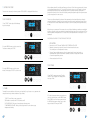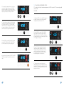
1
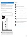
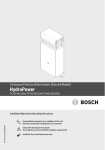
owner’s manual
Welcome to the future of hot water.
VOLT SS/X6/OP
DYNAMIC SS/X8/OP
CONTENTS
Symbols used in these instructions
Observe the following safety instructions:
Please Note:
Warning about possible dangers.
i
i
Congratulations on purchasing your new
system.
You are now the proud owner of Australia’s best value, best performing heat
pump. We spent over three years designing and developing the Hydrotherm
range to ensure that each unit will provide years of trouble free operation.
However, in order to perform optimally it is important to ensure that your
Hydrotherm is installed and operated inline with the instruction found in this
manual. Once operational there is little you need to do, except enjoy plenty
of affordable hot water.
Note:
Important information and tips.
1.0 Parts & Construction Schematic....................4
1.1 Heat Pump Schematic
1.2 Heat Pump Tank Schematic
2.0 Installation instructions.............................................. 6
2.1 Delivery
2.2 Location
2.3 Airflow
Note: Carefully read these
operating and installation
instructions and keep them safe.3.0
Should the equipment change
hands, pass these instructions to
the subsequent owner. Pass them
to the trained contractors for
servicing purposes.
2.4 Noise
Plumbing Schematics............................................................ 8
3.1 VOLT Connection Dimensions & Components
3.2 DYNAMIC Connection Dimensions & Components
4.0 Plumbing INSTALLATION...........................................................10
5.0 Electrical Connections....................................................12
For Outdoor use, or if its installed
inside minimum15m3 room volume
5.1 Electrical Schematic
5.2 Pre-Connection & Regulations
5.3 Hard Wiring the System
The Ambient of the appliance to
be used is -5°C to 35°C
6.0 Commissioning the system.........................................14
7.0 OPERATION PANEL INSTRUCTIONS................................16
7.1 Control / Display Interface
Positioning, installation and
commissioning must be carried out
by trained personnel working in
accordance with these operating
and installation instructions.
WARNING:
This appliance is not intended for
use by persons (including children)
with reduced physical sensory
or mental capabilities, or lack of
experience and knowledge, unless
they have been given supervision
or instruction concerning use of the
appliance by a person responsible
for their safety. Children should be supervised to ensure that they
do not play with the appliance.
The appliance shall be installed in
accordance with national wiring
regulations.
7.2 Display Panel
7.3 Setting The Clock
7.4 Timers
7.5 F11 Maximum Temperature Setting
7.6 F12 Temperature To Activate The Heat Pump
7.7 Other Settings
8.0 ERROR HANDLING............................................................................... 24
9.0 Trouble Shooting....................................................................... 25
10. SERVICE REPRESENTATIVE MaintenancE........... 26
11. Warranty........................................................................................................ 27
3
1.0 PARTS & CONSTRUCTION SCHEMATIC
1.1 SCHEMATIC VOLT-SS/X6/OP
1.2 SCHEMATIC DYNAMIC-SS/X8/OP
Cover lid
Top cover
Side cover
Front cover
Back cover
Screen panel
Electric board
Fan
Compressor
Evaporator
Host chassis
Condensate drain
Faceplate
Hot water outlet
Top cover
Control panel
Electrical inlet
Aluminum channel
Foam dampener
Fan housing
Compressor
Evaporator
Condensate collector
Condensate outlet
Faceplate
Hot water outlet
Safety valve outlet
Safety valve outlet
Tank cover
Tank cover
Hand grip
Hand grip
Insulation layer
Insulation layer
Condenser coil
Condenser coil
Cold water Inlet
Cold Water Inlet
Supporting frame
Supporting frame
660mm
570mm
48°
m
0m
66
1830mm
0m
57
1670mm
20m
m
m
30°
4
5
2.0 installation instructions
All Hydrotherm heat pumps are designed for installation by a licensed plumber in accordance with
standards set out in AS/NZS 3500.2 “National Plumbing and Drainage Code Hot Water Supply
Systems - Acceptable Solutions”
2.3 Air flow
600mm
• This unit is designed for external operation
only and requires a continuous supply of air to
operate efficiently.
2.1 delivery
• The Hyrdrotherm heat pump must be stored and
transported in a near vertical position at all times
with a tilt ratio of no more than 30°. Transporting
or storing the unit in a horizontal position will void
warranty.
• Avoid placing the system in locations with
multiple walls or structures (diagram 1 & 2).
• Always maintain optimum perimeter from all
structures.
Concrete
slab
Do not tilt
beyond 30°
Dynamic pallet for
transport only
2.4 noise
• The unit should be installed on a concrete plinth
capable of sustaining weights in excess of 480kg.
Proper drainage should be observed for any
overflow in accordance with AS/NZS 3500.2.
• Select a location that is removed from
bedrooms if possible as it is likely the unit will
function for a period of time during the night.
150mm
• If running noise becomes an issue, home
owners can utilise the built in timer functionality
to minimise operating hours to day time only.
Ambient noise conditions are much more
favorable in the day as oppose to night.
• If installed under fixtures or home eves, there
must be a minimum 600mm clearance between
the top of the unit and the structure.
• To prevent circulation of cold air the Hydrotherm
must be installed a minimum of 150mm off your
homes wall.
i
• To ensure correct air flow the Hydrotherm
must be installed with a minimum gap of 600mm
(Dynamic) or 200mm (Volt) between any vertical
structures.
Note: When installing do not install
less than 3 metres to a neighbour’s
window or door other than a
garage door or shed.
Noise levels
60
Noise levels (dB)
• The Hydrotherm range has been designed with
the lowest possible running noise level (>49db) to
ensure optimum comfort and minimum impact on
living areas.
2.2 Location
• When installed the Hydrotherm unit must be
completely vertical and level.
600mm
• Avoid installation in areas where falling debris
such as leaves is prevalent as this may result
in air vents being blocked or the unit being
damaged.
• The weight of an unfilled unit is between 76kg130kg. They must be handled by two people at all
times to avoid unnecessary strain and damage.
• Please note the outer casing of the unit is
susceptible to denting and damage. Care and
consideration should be taken into account
when moving the unit as any marks caused by
inappropriate handling are not deemed as
defects and are not covered under warranty.
600mm
49bB
50
40
30
20
10
For Wh Wa
est isp shi
er ng
Air
-co
Ma
chi
ne
nd
itio
ne
r
Concrete
plith
• The Hydrotherm should be installed so that the
control interface is accessible to users.
0° tilt
6
7
3.0 plumbing schematics
i
The following instructions and schematics have taken into account standards
AS4324, AS4020, AS1056.1, AS/NZS2712, AS/NZ3350.240/30/30.2, AS3498
and represents an optimum installation procedure for this unit however to ensure
minimum requirements are met all local regulations should be adhered too.
3.2 DYNAMIC Connection Dimensions and Components
3.1 VOLT Connection Dimensions and Components
1. Cold water supply outlet
(3/4” female thread)
2. Hot water outlet
(3/4’’ female thread)
3. Condensate drain
(20mm U.V stable piping)
4. P&T relief valve
(3/4’’ female thread 700Kpa)
5. Electrical cable
6. Tempering valve
(High performance)
7. Expansion control valve
(If required by council 600Kpa)
8. Pressure reduction valve
(500Kpa)
9. Non-return valve
10. Junction box
(Hard wired into 10Amp circuit)
*All lines must be run separately to
storm water drain. Lines can not be
connected to form a single run.
8
1. Cold water supply outlet
(3/4” female thread)
2. Hot water outlet
(3/4’’ female thread)
3. Condensate drain
(3/4” female thread)
4. P&T relief valve
(3/4’’ female thread 700Kpa)
5. Electrical cable
6. Tempering valve
(High performance)
7. Expansion control valve
(If required by council 600Kpa)
8. Pressure reduction valve
(500Kpa)
9. Non-return valve
10. Junction box
(Hard wired into 10Amp circuit)
*All lines must be run separately to
storm water drain. Lines can not be
connected to form a single run.
9
4.0 plumbing installation
PLUMBING CONNECTIONS
1. Cold Water Supply Outlet
• The cold water supply connection is a 3/4” female thread.
• The cold water supply should be connected to RP 3/4” socket.
• The cold water supply outlet can also act as a drainage point for emptying the system.
2. Hot Water Connections
• The hot water supply connection is a 3/4” female thread.
• The hot water supply should be connected to RP 3/4” socket.
• To ensure thermal efficiency all hot water lines and connections must be insulated with a minimum 13mm closed cell
insulation.
• All hot water supply parts must be constructed from copper. If using pipe of other material please refer to local
authorities for further instructions.
3. Condensate Drain
• The process of heat extraction from the atmosphere through evaporator coils results in the production of water in
the form of condensation. More humid environments will produce higher rates of condensation.
• To collect this water by-product a Condensate Tray is located on top of the water storage tank. Overflow from this
tray runs out through the Condensate Drain and supplied hosing.
• The Volt model condensate hosing is constructed from 25mm UV stable plastic and must be connected to
condensate outlet by the supplied hose clamp. The hose can be connected to another PVC or copper pipe, if further
length is required to reach drainage.
• The Dynamic model condensate connection is a 3/4” female thread, a RP 3/4” elbow socket should be connected
and 15mm copper piping used to transport condensate to nearest drain outlet.
• The condensate lines for both models must run to the nearest drain point. The condensate lines for both models
must not be connected into the PTR or ECV drainage lines, doing so will void all warranties.
• Ensure the condensate pipe remains free of kinks and is running down to ensure the free flow of water.
6. Tempering Valve
• This device is automatically programmed to produce hot water in excess of 50°C. As such in accordance with AS/
NZS3500 it is mandatory that “Tempering Valve” is installed.
• We recommend a high performance or solar rated tempering valve is used to ensure a more accurate hot water
delivery temperature.
• Your old hot water system might not have had a tempering valve installed before and therefore you will notice a
change in the temperature of the hot water. This is normal and required under the new legislation. Should you have
any concerns, please contact your installer.
7. Expansion Control Valve
• Observe the local requirements with regards to the installation of an ECV valve (optional in most counsels).
• When installing a ECV ensure that the connecting pipe has a diameter no greater than that of the safety valve.
• Ensure the drain is sized to allow for water runoff, even in incidents where the safety valve has been fully opened.
• The drain outlet must remain open to the atmosphere at all times and must not have a closing function.
• The recommended rating for the ECV valve is 600kPa, if PRV valve is 500kPa. If the PRV valve is 350kPa the ECV
should be rated at 500kPa.
8. Pressure reducing valve (rated maximum 500kPa)
• The maximum inlet pressure to the system must be no more than 500kPa.
• A pressure reducing valve must be used in the direct cold water supply line feeding into the system.
• Should the system be subjected to pressures above 500kPa all warranties will be void.
• This water heater is supplied with a PTR valve rated at 700kpa and is designed for direct connection to mains
water supply with a pressure not exceeding this rating. Should main pressure fluctuate above this rating, a pressure
limiting device (AS1357) should be connected at point 8 in above schematic.
9. Non-return Valve
• It is recommended that a non-returning valve is installed directly into the cold water supply line feeding the system.
This will allow the hot water system to be isolated from the rest of the homes water supply, making servicing, draining
and replacing the unit easy.
• The non-return valve can be combined with a PRV valve to form a duo valve as shown in the above schematic.
4. Pressure & Temperature Relief Valve
• The system is supplied with a loose Pressure & Temperature valve appropriate to the pressure rating of the water
heater tank. If the PTR valve is not present please contact your supplier. The valve rating is: 700kPa.
• The supplied PTR valve must be installed at point 4 in the installation schematics under the socket marked RELIEF
VALVE.
• The PTR valve must be insulated with a minimum 13mm closed coupled insulation, to minimize heat lost.
• The relief valve must be installed so that the drain line is facing downwards at all times with the discharge point
remaining open to the atmosphere.
IMPORTANT:
A discharge pipe connected to the pressure- relief device is to be installed in a continuously
downward direction and in a frost-free environment. Warning: Do no connect any pressure-relief
device to the vent pipe of this water heater. The water may drip from the discharge pipe of the
pressure-relief device. This pipe must be left open to the atmosphere. The pressure-relief device is to
be operated regularly to remove lime deposits and to verify that it is not blocked.
10
Filling The System
• Once the Hydrotherm has been connected to the properties plumbing as per instructions the tank
can be filled and pressurised.
• Open the non-return valve on the cold water inlet to begin filling the system with water. At the same
time insure at least one hot water tap is open inside the property. While the system begins filling with
water you will hear air being expelled from the open hot water tap. This is called bleeding the system
and insures there are no trapped air pockets. Once water begins running out of the hot water tap the
system is completely bled and you can turn the tap off.
• Always ensure that the tank is completely full before connecting and turning on electricity supply.
• When the system has been left running but no hot water has been used for a period in excess it is
recommended that hot water tap is left running for several minutes to ensure the dissipation of gases
through the plumbing network. Please do not smoke or have naked flames present during this time.
11
5.2 Pre-connection & Regulations
5.0 electrical connection
i
• Before any work can commence ensure that the heater is isolated from the power supply at the control panel.
• The Hydrotherm heat pump is designed for permanent fixed wiring to a
- CONTINUOUS TARIFF, single phase 240 volt AC supply
- Tariff 33 (QLD only) single phase 240 volt AC supply.
Only qualified electricians must carry out the installations of the Hydrotherm heat
pump to main power accordance with the following instructions.
• When connecting the unit work must comply with the local supply authority regulations as well as AS3000.
• The power rating of the unit is set at 10 amps as such the mains power supplying the unit must have a 10 amp
minimum circuit breaker fitted.
5.1 electrical schematic
• To gain access the electrician may remove the two connecting screws and raise the cover upwards off the unit base
exposing electrical works.
• Note this device is fitted with an over-temperature control cut-out. Under no circumstances must the water heater
be in operation without this safety device connected to the circuit. Re-setting and replacement of this device must only
be carried out by a qualified electrical contractor.
• (AS/NZS 60335-1 Clause 7.12.2): disconnection must be incorporated in the fixed wiring in accordance with the
wiring rules.
C
2
Tx/Rx
No1 C1/2 C1/2 C3/4
X
C5
N02 No3 No4 C3/4
X
No5
FUSE: 250V, T3.15A
5.3 HARD WIRING THE SYSTEM
1
1
2
2
3
3
G0
B1
B2
B3
G
GND
GND
Y
C
4
4
ID3
ID1
GND ID4
ID2
ID5
GND B4
Key/spv
2
Tx/Rx
G0
B1
B2
B3
G
GND
GND
Y
ID3
ID1
GND ID4
ID2
ID5
V
No1 C1/2 C1/2 C3/4
X
C5
N02 No3 No4 C3/4
X
No5
GND B4
• The Hydrotherm system is supplied with a 3 point
earthed plug and may be run off a standard power
socket or extension cord. Running the unit off the plug
is only for short periods of time, for example when an
electricion is delayed to your home.
• For continued long term operation the Hydrotherm
system must be hard wired into an isolated 10amp
circuit.
V
Key/spv
• We recommend having a qualified electrician remove
the units plug and utilise the power supply cord to wire
the system into a junction box.
OFF
ON
• The junction box must be rated for outdoor use and
should be fitted with an insolating switch as shown in
the diagram.
Depending on model type and
installation address, the Hydrotherm must
be connected to either a continous or
shoulder tariff power supply. Please refer
to your energy provider if you require
futher information.
If the supply cord is damaged, it must be
replaced by the manufacturer, its service
agent or similarly qualified person in
order to avoid a hazard.
12
This appliance shall be installed in
accordance with National wiring
regulations AS.3000.
13
6.0 commissioning system
Pre-START PROCEDURES AND CHECKS
• Once both the electrical and plumbing connections have been completed by qualified trades person, the system is
now ready for operation.
• Before turning the system on it is essential that you ensure the Heat Pump storage tank is full and the device
thoroughly flushed.
• Bleed air from system via a hot water tap. Do not use a pressure and temperature valve.
• Ensure the device is resting on a smooth flat concrete plinth and that a condensate drain is installed from the
condensate port to an appropriate drainage point.
• Ensure that your plumber has insulated with high temperature closed cell insulation to prevent heat loss.
• Ensure that air can flow freely around the intake vents.
CHECKBOX
Make sure the unit is level.
Ensure the condensate and PTR lines are separate to the drain.
Ensure the condensate and PTR lines running down to allow the water to run off.
Ensure the unit is connected to Tariff 11 or 33 in QLD.
Ensure there is 600mm above the Dynamic to allow the lid to be removed for
maintenance.
Ensure there is 200mm above the Volt to allow the lid to be removed for maintenance.
Ensure the unit has 150mm of space between the exterior of the tank and wall for air
circulation.
Ensure the unit is set at 60°C in F11 setting and the drop down temperature is 5-10°C
in F12 setting. Please refer to section 7.0 in the user manual.
Ensure the plumber has explained the purpose of the tempering valve.
Once you have carried out all these checks you are ready to switch on the unit.
WARNING: This appliance is not intended for use by persons (including children) with reduced physical
sensory or mental capabilities, or lack of experience and knowledge, unless they have been given
supervision or instruction concerning use of the appliance by a person responsible for their safety.
Children should be supervised to ensure that they do not play with the appliance. The appliance shall
be installed in accordance with national wiring regulations.
14
15
7.2 display panel
7.0 OPERATION PANEL INSTRUCTIONs
•
•
•
•
All functions and settings of the Hydrotherm are displayed on the DISPLAY PANEL. When a function is active, it is lit
up in either blue or red. Below, you can find the description of each function of the Hydrotherm and its location on
the panel.
KEY FACTORS:
All units should be set in Auto Mode unless the timers are required. To set the modes
press the ‘MODE’ button, this will change it from ‘AUTO MODE’ to ‘ECON MODE’.
Press again if you want to revert back.
Optimum temperature 60°C
Temperature Differentiation 5°C (Heat Pump heating cycle begins at 55°C)
Timers - Customise usage but be aware of temperatures, tariffs and usage patterns.
2
ECON MODE
ANY ISSUES OR QUERIES?
Please contact Hydrotherm TOLL-FREE 1300 769 904
AUTO MODE
7.1 CONTROL / DISPLAY INTERFACE
3
8
OFF
9
ALM
10
H
SET TEMP
HTG
°C
DEF
WATER
WARM
Located on the front of the Hydrotherm is the unit interface. It houses all controls and displays necessary to operate
your new Hydrotherm Hot Water System. The legend below indicates all components referred to in this manual.
ON
OFF
P1
P2
P3
°C
1. DISPLAY PANEL
2. UP/DOWN ARROWS
1
3. TIMER
4. CLOCK
ECON MODE
5. MODE
AUTO MODE
6. ON/OFF
OFF
HTG
DEF
ALM
H
5
6
7
SET TEMP
°C
WARM
1
WATER
ON
OFF
P1
P2
P3
°C
6
1. ‘WORKING MODE’ - [ AUTO / ECON ]
AUTO - Automatic setting
ECON - Timer setting
5. ‘P1 / P2 / P3’ - Three different timers that can be set
2. ‘STATUS’ - [ OFF / HTG / DEF / WARM ]
OFF - Unit is not operational
HTG - Heating the water, heater activated
DEF - Defrosting of the pipes and apparatus
WARM - The water is warm and ready for use
7. ‘TEMPERATURE GRADIENT’ - Shows the quantity of
hot water in the tank available
5
3. ‘CLOCK DISPLAY’
3
16
4
4
4. ‘TIMER’ - [ ACTIVE / ON / OFF ]
ACTIVE - Indicates that a timer is has been set and activated
ON - Identifies the ON timer is being set
OFF - Identifies when the OFF timer is being set
6. ‘WATER’ - The current water temperature in the tank
8. ‘ALM’ - Alarm representing a fault in the machine,
contact your supplier
9. ‘H’ - Alarm identifying water temperatures exceeding
the temperature allowed
10. ‘SET TEMP’ - Maximum temperature of the water in
the tank, the heater cuts off once the water reaches this
temperature
17
7.3 SETTING THE CLOCK
The correct time is necessary for the unit to operate in ‘ECON MODE’. It is displayed in 24 hour format.
TO SET THE CLOCK:
When considering the tariffs, the shoulder tariff ensures you will receive 18 hrs of electricity minimum a day. However,
it can be during peak periods such as 7 - 9 am and 4 - 8 pm that the electricity is cut off. Therefore if your usage
peaks during this period and you set a timer preventing the unit from switching on during the evening there is
potential that the unit will run out of hot water the following morning following another peak. It is important to ensure
you allow enough time for the unit to recover.
The unit is most efficient during the day because of the temperature, but often household peak use is during the
evening and therefore the unit needs to recover over night to provide hot water the next morning. However, if there
is a noise issue the unit can have multiple timers set, allowing it to work in the evening and then again the following
morning.
1. Press ‘CLOCK’. The hour digits will flash indicating
they can be changed.
CLOCK
When the unit is on continuous tariff it has access to electricity all day and therefore no consideration is needed with
regards cut off periods. Just take into account cooler temperatures and peak usage. The unit can deliver up to 77L an
hour during ambient air temperatures of 20°C. However in the cooler temperatures the unit can require 5 - 6 hrs of
heating time.
IMPORTANT: ALLOW PLENTY OF TIME FOR THE UNIT TO RECOVER
KEY FACTORS:
•
•
2. Use the ‘ARROW’ buttons to select the correct hour.
To advance to minutes, press ‘CLOCK’,
•
CLOCK
•
Ensure the unit is in ‘ECON’ mode. TIMERS WILL NOT OPERATE IN AUTO MODE
Remember, the timers are just a period of time which the machine can heat the water. The overriding factor is the temperature of the water.
There are 3 timers available, ensure you allow a long enough period of time to heat the tank, it is
recommended that a period of 8 hrs minimum is available, as weather can change and the amount
of water that requires heating can alter.
All timers are based on a 24 hr clock.
TO SET TIMER:
3. Use the ‘ARROW’ buttons to select the correct
minutes. To finalise, press ‘CLOCK’. The clock is now set.
CLOCK
1. Press ‘TIMER’ to initiate timer settings.‘P1’ and the
‘TIMER ON’ icon will appear on the display and the
hour digits will flash.
TIMER
7.4 TIMERS
The timer(s) function is available to allow the unit to work specifically for you. However it is very important when
setting the timers that you take into consideration 3 key variances:
1. TARIFF - The tariff that your unit is connected to:
300L (shoulder or continuous tariff) / 190L (continuous tariff)
2. HOT WATER USAGE - Be aware of your peak usage and recovery times.
3. TEMPERATURES & CLIMATES - Ensure you allow enough time for the unit to heat in varying
temperatures and humidity.
2. The first clock represents the time you want the unit to
come on. To adjust the hours, use the ‘ARROW’ buttons.
Select ‘TIMER’ to switch from hours to minutes and use
the ‘ARROW’ buttons again to adjust. Once you have
input your desired ‘ON’ time, press ‘TIMER’.
TIMER
18
19
7.5 F11 MAXIMUM TEMPERATURE SETTING
F11 is used to set the tank’s maximum temperature. It MUST be set at 60°C to ensure legionella
control is met.
3. The second clock represents the time you want the
unit to shut off. To adjust the hours, use the ‘ARROW’
buttons. Select ‘TIMER’ to switch from hours to minutes
and use the ‘ARROW’ buttons again to adjust. Once you
have input your desired ‘OFF’ time, press ‘TIMER’.
TO SET F11:
TIMER
1. Hold down ‘MODE’ until the word ‘PASS’ appears on
the display. This requires you to enter the password.
The password for each machine is 4-3-2-1.
4. P1 has now been successfully set. As the three timers
can only be set in succession the next clock represents
the ‘ON’ time for timer 2 or ‘P2’. If you don’t require
additional timers, press TIMER repeatedly until you see
the original clock display. If you do want to set these
extra timers, follow the steps outlined in steps 2 & 3.
MODE
2. Press ‘UP ARROW’ to change ‘PASS’ to ‘0000’.To
enter the password, adjust each number using the
‘ARROW’ buttons and select ‘TIMER’ to confirm. When
the password has been correctly entered, press ‘TIMER’.
‘F11’ will appear on the display.
TIMER
5. Press ‘MODE’ to activate ‘ECON MODE’. If the unit
is left in ‘AUTO’, TIMERS WILL NOT OPERATE. ‘ECON
MODE’ should now be lit up on the display panel.
TIMER
3. To enter F11 maximum temperature setting, press
‘TIMER’ and a number will appear on the screen.
This number indicates the temperature to which the
tank will be heated. To ensure legionella control,
the temperature MUST be set at 60°C, which is the
maximum temperature the unit can be set to.
MODE
6. Switch the unit on by pressing ‘ON/OFF’. The ‘ACTIVE
TIMER’ icon should light up, as well as the current unit
status.
TIMER
ON/OFF
4 To adjust the number on the display use the
‘ARROW’ buttons to set it to the Max of 60°C. THIS IS
THE CORRECT TEMPERATURE AND SHOULD NOT BE
ALTERED. To set and exit, press the ‘TIMER’ and ‘F11’ will
reappear on the screen.
TIMER
20
21
4. The number displayed is the amount in degrees the
water temperature can drop before the heat pump
is activated. To adjust, use the ‘ARROW’ buttons. To
confirm and exit, press ‘TIMER’. The screen should
display ‘F12’.
The recommended setting is 5 degrees. This will ensure
the heater activates when the average temperature
drops from 60°C to 55°C.
5. To exit settings press ‘UP ARROW’ until ‘END’ appears
on the screen, then press ‘TIMER’. The clock will
reappear on the screen.
TIMER
TIMER
5. To exit settings press ‘UP ARROW’ until ‘END’ appears
on the screen. Press ‘TIMER’ to save settings and exit.
The clock will reappear on the screen.
7.6 F12 TEMPERATURE TO ACTIVATE THE HEAT PUMP
The F12 setting allows you to set a value to which the water temperature can drop before the heat pump will
automatically start heating.
TO SET F12:
TIMER
1. Hold down ‘MODE’ until the word ‘PASS’
appears on the display. This requires you to enter
the password.
The password for each machine is 4-3-2-1.
7.7 OTHER SETTINGS (extra large hot water demand)
F19 - If there is an extra-large demand, Hydrotherm can heat water to 65°C. This means less hot water has to be
taken for each shower and the tank will deliver between 20 - 40 litres of extra hot water.
MODE
F54 - If you set the tank to an increased heat then you need to adjust the F54 setting to 0 to ensure the A6 alarm is
not activated.
These are advanced settings that we recommend leaving default. If you are certain you require these settings, please
contact us before attempting to alter.
2. Press ‘UP ARROW’ to change ‘PASS’ to ‘0000’.
To enter the password, adjust each number
using the ‘ARROW’ buttons and select ‘TIMER’ to
confirm. When the password has been correctly
entered, press ‘TIMER’. ‘F11’ will appear on the
display.
TIMER
3. To reach ‘F12’ press ‘DOWN ARROW’, then
‘TIMER’ to enter F12 settings.
TIMER
22
23
8.0 ERROR HANDLING
ERROR STATUS
REASONS
ERROR HANDLING
A1
Thermal sensor alarm
Water temperature
sensor open circuit or
short circuit.
1. Check the water temp. sensor
connection.
2. Change the water temp. Sensor.
A2
Condenser coil sensor
alarm
Condenser coil temp.
Sensor open circuit or
short circuit.
1. Check the condenser coil
temperature sensor connection.
2. Change the coil sensor.
A3
Exhaust sensor alarm
Exhaust temp. Sensor
open circuit or short
circuit.
1. Check the exhaust temperature
sensor connection.
2. Change the exhaust temperature
sensor.
A4
Ambient temp. Sensor
alarm
Ambient temperature
sensor open circuit or
short circuit.
1. Check the Ambient temperature
sensor connection.
2. Change the ambient temperature
sensor.
A5
Low/High pressure
alarm
1.1 High pressure
protection switch off.
1.2 Ambient temperature
too high or water heat
exchanger dirty block.
2.1 Low pressure
protection switch off.
2.2 Leakage of
refrigerant.
1.1 Check or change the high pressure
protector.
1.2 Check if the surround temp. Is too
high, or clean the heat exchanger of
water tank.
2.1 Check or change the low pressure
protector.
2.2 Supply refrigerant and check if
there is any leakage.
A6
(Auxiliary) electric
heater protection
overheat alarm
1. Electric heater
protection switch off.
2. Tank water temp. Too
high
1. Check if the water temp is as LCD
display, or if water temperature is too
high.
2. Change the Electric heater.
A7
Exhaust temperature
too high
1. Lack of refrigerant.
2. Mix with air in system.
3. Lack of lubricating oil.
1. Supply refrigerant.
2. Re-vacuumizing, and fill in refrigerant.
3. Change the lubricating oil
ofcompressor.
ERROR CODE
--
24
9.0 TROUBLE SHOOTING
Screen no display or
display insufficiency
1. No plug in power.
2. Mainboard and
operation panel
communication
break off.
1. Check the power line and voltage.
2. Reconnect the line of mainboard and
operation panel.
3. Change the mainboard or operation
panel.
Pressure & Temperature Relief Valve
It is not unusual for the PTR to allow a small quantity of
water to escape during the heating cycle. The amount
of discharge will depend on the hot water usage.
Continuous Trickle
This is most likely due to a build up of foreign matter.
In this case try gently raising the easing lever on
the Pressure and Temperature Relief valve for a few
seconds then release gently. This may dislodge small
particles of foreign matter and rectify fault.
Steady Flow (PTR)
This may be caused by excessive water supply
pressure, a faulty Pressure & Temperature Relief Valve
or faulty thermostat > Turn off electricity supply, turn off
the water and contact AQUATECH agent.
No Hot Water
Is the Pressure & Temperature Relief Valve discharging
to much water?
Do you have the correct size water heater for your
requirements?
Is one outlet (such as a shower) using more hot water
than you think?
Carefully review families hot water usage and
if necessary check the flow rates with a bucket,
measuring the amount of water used over the period
of the three days. If usage is higher than output a
control valve may be useful in reducing pressure and
usage at the end of the line.
Consider that during night time heating, the time to
recuperate hot water is lengthened due to cooler
conditions, so you may find the tank has not fully
recovered from high use periods.
Condensation is Dripping From Inside
Check that the discharge location of the condensate
drain has not been blocked thereby restricting the
condensation flow away from the heat pump.
The Heat Pump Does Not Run
Check the power supply is turned on and that
the house circuit breakers or fuses are on and
operational. If problem persist contact your Aquatech
representative.
System Maintenance
The heat pump water heater is designed to eliminate
system maintenance other than that detailed in this
Owner’s Manual.
Personally inspecting or servicing any part of the
system is not recommended.
Should you decide to personally inspect the system,
it is essential that you observe all normal safety
practices.
Most importantly, the electricity supply must be turned
OFF.
Every 5 years you should contact the local service
agent to replace all safety valves to ensure continued
system life and operational safety. In locations where
the potable water has a TDS greater than 600 ppm,
this service is recommended every 3 years.
Safety Information
For safe performance this water heater is fitted with:
An over-temperature energy cut-out thermostat.
A combination Pressure & Temperature Relief Valve
These devices must not be tampered with or removed.
The water heater must not be operated unless both of
these devices are fitted and in working order.
The element cover should only be removed by an
electrician. The electrical power.
Supply switch must be turned off and the fuse removed
at the main electrical supply switchboard before the
water heater electrical cover is removed.
The Pressure & Temperature Relief Valve should be
checked for adequate performance or replaced
at intervals not exceeding 5 years or less if local
regulations apply. The lever on the relief valve should
be pulled to operate at least once every 6 months.
Note: The pressure & temperature relief valve and the
drain outlet pipe must not be sealed or blocked. It is
normal for the valve to overflow during heating cycles.
Danger: Failure to operate the relief valve easing gear
at least once every six months may mask a problem
with the water heater.
WARNING: If the hot water system is not used for two weeks or more a quantity of highly flammable
Hydrogen gas may accumulate in the water heater. To dissipate this gas safely, it is recommended
that a hot tap be turned on for several minutes or until discharge of gas ceases, use a sink, basin, bath
outlet, but not a dishwasher, clothes washer or other appliance. During this procedure, there must
be no smoking, open flame or any electrical appliance operating nearby. If hydrogen is discharged
through the tap, it will probably make an unusual sound as with air escaping
25
35% Refund of purchase price **
Year 10
30% Refund of purchase price **
Year 11
25% Refund of purchase price **
Year 12
20% Refund of purchase price **
Year 13
15% Refund of purchase price **
Year 14
10% Refund of purchase price **
Year 15
5% Refund of purchase price **
L
40% Refund of purchase price **
Year 9
-PA
R T S WA R R
A
AL
Year 8
Y
45% Refund of purchase price **
NT
L
Effective for Aquatech All-In-One water heaters manufactured and sold after 08/08/2010
50% Refund of purchase price **
Year 7
AL
For Advice Repairs and Service call 1300 769 904
Full Replacement of system *
Year 6
Y
The service procedure should include the following steps.
• Replace/service the Pressure and Temperature relief valve.
• Flush the water heater, drain and flush the water heater
as follows.
• Turn off power to unit.
• Turn off the cold water supply to the water heater at the isolating valve.
• Gently operate the release lever on Pressure and Temperature relief valve to release pressure in the tank.
• Disconnect the cold water inlet union to the heater and attach a drain hose.
• Operate the pressure and temperature relief valve to allow air into the heater and allow water to escape through
the hose.
• To flush water heater carry out above steps. Disconnect the hot water inlet union and attach a water supply hose
to the heater. Turn on water supply.
• Flush the heater until clear water appears then reconnect all fittings, fill heater and restore the power supply.
Year 1-5
NT
5Yr service of system - Authorized personnel only
A five year service should be carried out on all units by a licensed tradesperson.
15YR PRO-RATA TANK WARRANTY
The 304 stainless steel tank is warranted to last 15 years Pro-Rata under normal
use. Below is the guideline for Pro-Rata arrangement, should your tank fail during the
warranty period from date of install.
A
Relief of air vacuum in pipes and system
• To bleed air from the system and pipe work.
• Drain and flush unit as per maintenance guidelines.
• Commission unit ensuring all the air is bled from the system by turning on all hot water taps.
• Do not attempt to bleed air via the pressure and temperature relief valve.
Aquatech Solar Technologies Australia warrants all models under the Hydrotherm branding as per the following
terms and conditions. The obligation of Aquatech or its service agents under this warranty is limited to Aquatech
either repairing or replacing any defects/parts at its discretion within the specified warranty period as stated.
R T S WA R R
Cleaning the evaporator
• To ensure the optimum efficiency the system evaporator should be cleaned regularly.
• Clean evaporator using water and a soft brush only.
Draining the System
• Close the shutoff valve in the cold water supply
• Fully open the taps at all draw off points.
• Drain cylinder via cold water inlet line.
• Undo cold water inlet and let all residential water escape. - Warning water maybe hot when draining.
11. warranty - australia only
-PA
10. Service Representative Maintenance
Should the inner tank fail within this warranty period Aquatech Solar Technologies will
provide a replacement system of equal or greater capacity. The system will be provide
at no charge, however all additional costs for installation and shipping will be the
responsibility of the claimer.
The Refund value is based as a percentage of the final invoiced price as charged to
the purchasers credit card, through the Aquatech Online Store. The Pro-Rata invoice is
only applicable to purchases made online through Aquatech.
This warranty is void if the TDS (Total Dissolved Solids) of the water is in excess of
600ppm (parts per million), or due to any corrosive elements within the water supply
with a copper content.
This warranty is void if there is a high chloride water supply areas, the water can
corrode some parts and cause them to fail. Where the chloride level exceeds 250 mg
litre warranty does not apply to the heat pump unit and tank unit. pH is a measure of
whether the water is alkaline or acid. In an acidic water supply, the water can attack
the parts and cause them to fail. No warranty applies to the heat pump unit and
tank unit where the pH is less than 6.0. The water supply from a rainwater tank unit
in a metropolitan area is likely to be corrosive due to the dissolution of atmospheric
contaminants. Water with a pH less than 6.0 may be treated to raise the pH. It is
recommended that an analysis of the water from a rainwater tank be conducted before
connecting this type of water supply to the system.
5Yr All Parts
All system component parts as outlined in the model schematic found in this document,
are covered under this warranty for a period of five years, from date of install.
This is for supply of spare components only and does not include cost of labour for
reconnecting component parts. Aquatech will cover the shipment of parts to residence
or repair agent under this agreement.
26
27
warranty - australia & NEW ZEALAND
TERMS OF MANUFACTURER’S WARRANTY
Each unit is supplied with a PTR Valve, all other valves (see 4.0 plumber schematics) have to be supplied by the
installer in accordance with State and local regulations, failing to use new valves when installing any Aquatech system
will cancel all warranties. This Warranty only applies to Australia & New Zealand.
The air filter must be cleaned at least once a year and free from a build-up of dirt/dust, which will affect or restrict
the air flow.
CHARGEABLE REPAIRS
A charge will be made if the cause of the break-down is due to any of the following:
Faults caused by, external electrics and external components & incorrect installation methods.
The Aquatech Heat Pump has not been commissioned, in accordance with the installation and servicing manual, or
by a licensed plumber.
BREAKDOWN DURING THE MANUFACTURER’S WARRANTY
If your Aquatech Heat Pump should fail within the warranty period, you must contact Aquatech Australia who will
arrange for the repair or replacement under the terms of their Warranty.
IN THE FIRST INSTANCE
Contact your plumber to ensure that the fault does not lie within the system or any other components, or any
incorrect setting of the system controls.
IF A FAULT IS FOUND
Ask your installer to contact Aquatech Australia service department who will arrange with the Service Plumber/
Electrician to attend to the fault.
FREE OF CHARGE REPAIRS
During the warranty period no charge for parts or labour will be made providing that the Heat Pump has been
installed and commissioned correctly in accordance with the manufacturer’s instructions. Proof of ‘purchase’ date must
be provided upon request. The free service is restricted and will only apply to Metropolitan areas, in all other areas
the free service will still apply subject to the hot water unit heater or any parts being forwarded, to the nearest
service agent, transport is required to be prepaid both ways at the owner’s risk.
CUSTOMERS DETAILS
Heat pump supplied by:
PLUMBERS / ELECTRICIAN DETAILS
Name:License Number:
Address:
Phone Number:
Installation Date:
Model:Serial Number:
Address of Installation:
Scope of Works:
New Home / Replacement
28
NOTES
[email protected]
www.hybridhotwater.com.au
TOLL-FREE 1300 769 904