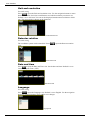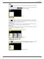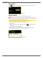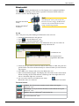
1
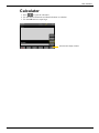
E910
E915
MANUAL FLANGE
English
05-0400 Revision 2
Content
Introduction
User Interface
7
11
Navigation buttons
12
OK buttons
12
Function buttons
12
Screen dump
12
Status bar
13
LED signals
13
Battery
14
Display unit
14
Detector
14
Bluetooth units
®
14
Calculator
15
Measurement file handling
16
Save measurements
16
Open measurements
16
Copy to usb memory
16
Generate PDF reports
16
Download to PC
16
Settings
17
Filter
17
Unit and resolution
18
Detector rotation
18
Date and time
18
Language
18
User 19
Backlight
19
Automatic power off
19
Information 20
System update 20
Bluetooth®
21
General information
23
Values
25
Values target 25
Register values
25
Halve or Zero set value
26
Zoom
26
Tolerance
26
Values table
27
Function buttons 27
Automatic recording
28
Flange flatness
29
Set up
30
Measuring procedure
31
Enter distances
31
Measure
31
Flange result
32
Flange 3D view 32
Flange Graph view
32
Flange Table view
32
Reference points
33
Taper result
35
Flange parallelism
37
Set up
38
Measuring procedure
39
Enter distances
39
Measure point 1 to 4
39
Measure point 5 to 8
40
Function buttons 40
EasyLink™
41
Install and setup
42
Working with EasyLink™
44
Flange program
47
Technical data
51
Display unit E418
52
Laser transmitter D22
53
Laser transmitter D23 Spin
54
Tilting screws
54
Detector E5
55
Angular prism D46
56
Tripod
56
6

Introduction
Damalini AB
Damalini AB develops, manufactures and markets Easy-Laser® measurement and
alignment equipment based on laser technology.
We have more than 25 years of experience from measurement tasks in the field and
product development. We also provide measurement service, which means that we ourselves use the equipment we develop, and continuously improve it. Because of this we
dare to call ourselves measurement specialists.
Do not hesitate to contact us about your measurement problems. Our expertise will
help you solve it in an easy way.
Declaration of conformity
Equipment: Easy-Laser® product range
Damalini AB declares that the Easy-Laser® product range is manufactured in conformity with national and international regulations. The
system complies with, and has been tested according to the following
requirements:
EMC Directive
Low Voltage Directive
Laser Classification
RoHs Directive
WEEE Directive
2004/108/EG
2006/95/EC
Europe: SS-EN-608 25-1-1994
USA: CFR 1040.10/11 - 1993
2002/95/EG
2002/96/EG
Disposal of old electrical and electronic equipment (Applicable throughout the European Union and other European countries with separate collection
programs)
This symbol, found on product or on its packing, indicates that this product should not be treated as household waste when disposed of. It should
be handed over to an applicable collection point for the recycling of
electrical and electronic equipment. By ensuring this product is disposed
correctly, you will help to prevent potential negative consequences to the
environment and human health. For more detailed information about the
recycling of this product, please contact your local city office, household
waste disposal service or the retail store where you purchased this product.
Quality certificate
Damalini AB is ISO 9001:2008 certified. Certificate number 900958
Damalini AB confirm, that our products are produced according to applicable national
and international regulations and standards. All components are checked before assembly and final products are tested in functionality and visually checked before delivery
The calibration of the equipment fully complies with ISO9001: 2008 #7.6
7
Introduction
Limited warranty
This product is manufactured under Damalini’s strict quality control system. Should
the product fail within two (2) years from the date of purchase under normal usage
conditions, Damalini will repair or replace the product free of charge.
1.Using new or refurbished replacement parts.
2.Exchange the product with a product that is new or which has been manufactured
from new or serviceable used parts and is at least functionally equivalent to the
original product.
Proof of purchase date should be confirmed, and sent together with a copy of the original purchase document.
Warranty is valid under normal usage described in the user’s manual appended with
the product. The warranty comprises failure on Easy-Laser® product that could be
related to material and/or fabrication errors. The warranty is valid only in the country
of purchase.
The warranty is not valid in the following cases:
• If the product is broken due to mishandling or incorrect operation
• If the product has been exposed to extreme temperature, calamity, chock or high
voltage.
• If the product has been modified, repaired or disassembled by unauthorized personnel.
Compensation for possible damage due to failure on Easy-Laser® product is not included in the warranty. Freight cost to Damalini is not included in the warranty.
Note
Before delivery of the product for warranty repair, it is the responsibility of the buyer
to backup all data. Data recovery is not included in the warranty service and Damalini is not responsible for data that may be lost or damaged during transit or repair.
8
Introduction
Safety precautions
Easy-Laser® is a laser instrument in laser class II with an output
power less than 1 mW, which requires the
following safety precautions:
• Never stare directly into the laser beam
• Never aim the laser beam at anyone else’s eyes.
Note!
Opening the laser units can result in hazardous radiation, and will invalidate the
manufacturer warranty.
If starting the machine to be measured would result in injuries, the possibility to unintentionally start it must be disabled before mounting the equipment, for example by
locking the switch in the off position or removing the fuses. These safety precautions
should remain in place until the measurement equipment has been removed from the
machine.
Note!
The system should not be used in explosive risk areas.
Disclaimer
Damalini AB and our authorized dealers will take no responsibility for damage to
machines and plant as a result of the use of Easy-Laser® measurement and alignment
systems.
Even though great efforts are made to make the information in this manual free from
errors, and to make the information complete for the user, there could be things we
have missed, because of the large amount of information. As a result of this, we might
change and correct these things in later issues without further information. Changes to
the Easy-Laser® equipment may also affect the accuracy of the information.
Copyright
© Damalini 2009
19 June 2009
Fredrik Eriksson
Quality Manager, Damalini AB
Street Address: Damalini AB, Åbäcksgatan 6B, SE-431 67 Mölndal, Sweden
Postal Address: Damalini AB, PO Box 149, SE-431 22 Mölndal, Sweden
Phone: +46 31 708 63 00, E-mail: [email protected]
Web: www.damalini.com
9

10
User Interface
LED signals
OK
Navigation buttons
Numeric buttons
Function buttons
A
Connection for external power.
B
Network connection.
C
External connection. Use for projector for example.
D
USB A (master). Use for usb memory.
E
USB B (slave). Use for connecting to a PC.
F
Connection for Easy-Laser® equipment.
G
IP protection only when sealed
Battery compartment
A
B
C
D
E
F
G
11
User Interface
Navigation buttons
To navigate on the screen, use the navigation buttons. The selected icon is marked with
a yellow frame. The navigation buttons are also used to move between the buttons in a
submenu and to change the values in the fields.
Navigation buttons, use the up button to take screen dumps
OK button
Numerical buttons
OK buttons
There are two green OK buttons and they both work in the same way. Press OK to
select the currently selected icon for example.
Function buttons
The icons above the function buttons change depending on which view is currently
displayed on screen.
Function buttons
Submenus
The function buttons marked with an arrow contain a submenu. Press and hold the
function button to display the submenu.
Selected icon in
submenu
Press and hold to display submenu
Screen dump
It is possible to take screen dumps of what is currently displayed on screen. You can
copy the screen dump to a usb memory. You can e-mail the screen dump or use it for
different kinds of reports.
Take a screen dump
Press and hold the navigation button “up” for 5 seconds. The screen dump is saved in
the file system as a .jpg file. It is named with current date and time.
Copy screen dump to usb memory
1.Insert a usb memory in the Display unit.
to open saved files. Select a screen dump and press
2.Select
12
.
User Interface
Status bar
The Status bar contain additional information such as warning icon, current time and
Bluetooth® connection.
Status bar
Measurement unit.
Change units via
Settings.
There are also text messages regarding:
• The selected icon.
• Hints on what information you are expected to fill in.
Status bar icons
Warning. Press the function button
regarding the warning.
to get additional information
Display unit charging. Indicating that a power adaptor is plugged in.
Hourglass. The display unit is in the middle of a task.
Peripheral. Indicates that a peripheral device is plugged in, such as a
projector.
Bluetooth®. Indicates that the Bluetooth® functionality is activated. The
number beside indicates the number of Bluetooth® units connected.
LED signals
Right indicator
Yellow
Flashing: The internal battery in the Display unit is charging.
Left indicator
Left indicator has several functions and colours:
Red/Blue Quick flashing: Reprogramming the system.
Flashing: Warning, for example low battery.
Red
Flashing: Searching for detectors equipped with Bluetooth®.
Blue
Green
Light
blue
Fixed light: Connected to detectors equipped with Bluetooth®.
Flashing: Display unit is starting.
Fixed light: The internal battery in the Display unit is fully loaded.
Blinking: Backlight is off, but the Display unit is still on. Press any
button to activate the Display unit.
13
User Interface
Battery
Select
to display the Battery view. This view gives you a good overview of the
battery status of all connected equipment.
Display unit
Dry cell batteries
Batteries empty (or dry cells
not inserted)
Detector
Battery charging
Detector’s
serial number
Display unit
The Display unit can be used from -10ºC to +50ºC. Charge the Display unit within the
temperature range of ±0ºC to +40ºC. You can charge the Display unit via:
Power adaptor
With the power adaptor plugged in, you can keep on
working as before.
USB
A PC via usb cable
While you have this connection, the Display unit is
blocked.
Dry cell batteries
When you get a battery warning, insert four R14 dry cell batteries in the battery compartment. This will prolong the power of the Display unit so that you can finish your
measurement.
Detector
The detector is charged by the Display unit when connected by cable. If you are using
Bluetooth® units, switch to cable when the detector is low.
Bluetooth® units
The Bluetooth® units are powered by the Detector. To save energy, the Bluetooth®
units are only connected when you are using a measuring program. There is no power
switch on the unit. To switch off, simply unplug the unit. See also chapter Bluetooth®.
14
User Interface
Calculator
1.Press
to open the calculator.
2.Use the numerical buttons and function buttons to calculate.
3.Use the OK button as equal sign.
Press and hold to display sub-menu
15
User Interface
Measurement file handling
Save measurements
Press
(found under
) to save a measurement. You are prompted to select
a name. The date and time will automatically be added to the file name. The measurements that you save will be available to the other users as well.
Open measurements
Select
(found on the start view and in Settings) to open saved measurements.
The File view is displayed. Here you can easily see who has saved the file, when and
from which program it was saved. You see the files saved by all users.
xml
jpg
pdf
A measurement file. Select a file and press OK to open.
A screen dump.
A report.
Copy to usb memory
You can easily copy a saved measurement or other files to an usb memory. This way
you can transfer it to your computer for further analysis or for printing reports.
1.Insert a usb memory.
. The Open file view is displayed.
2.Press
.
3.Select the file you want and press
4.A folder is automatically created on the usb memory. The file is saved in the folder
F:\Damalini\archive\.
Generate PDF reports
In the present situation, only English is available in reports. This will be updated
shortly.
.
1.Press
2.Name the file and press OK. A report is generated and saved in the filing system.
3.To transfer it to a PC, copy it to a usb memory, see instructions above.
Download to PC
1.Start the Display unit.
2.Connect the usb cable between the Display unit and PC.
3.While you have this connection, the Display unit is blocked.
4.View and/or copy the files to the PC.
16
User Interface
Settings
Select
to open the Settings view. Some of the settings are personal and will be
default next time you start the system.
Settings view
Filter
Press
to open the Filter view.
If the laser beam passes through air with varying temperature, this may influence the
direction of the laser beam. If measurement values fluctuate, this could mean unstable
readings. Try to reduce air movements between laser and detector by, for instance,
moving heat sources, closing doors. If the readings remain unstable, increase the filter
value (more samples will become available to the statistical filter).
Filter values
Use as short a time as possible that still produces acceptable stability during the measurement. Default is set to 1. Normally you will use a filter value of 1-3.
Filter view
17
User Interface
Unit and resolution
Personal setting
to open the Units and resolution view. Use the navigation buttons to move
Press
between the fields. Set inches or millimeters and which resolution you want to use.
Default is set to 0.01 mm. You can set the displayed measurement resolution to 0.001
mm. The selected unit is shown on the Status bar.
Unit and resolution view
Detector rotation
Personal setting
The coordinate system can be rotated 90º. Press
view.
to open the Detector rotation
Detector rotation view
Date and time
Press
to open the Date and Time view. Set the date and time. Default is set to
Central European Time. (CET)
Date and time view
Language
Personal setting
Press
to open the Language view. Default is set to English. Use the navigation
buttons to select a language. Press OK to save changes.
Language view
18
User Interface
User
Press
settings.
to open the Users view. A user account is used for storing your personal
Use the function buttons
to add or remove users. To switch user, simply select the user you would like to switch to and press OK.
User view
Backlight
Personal setting
Press
to open the Backlight view. Use the navigation buttons to move between
the fields. Press OK to save changes. When backlight is off, the left LED signal will
flash to indicate that the Display unit is still on.
Backlight level
Adjust the backlight to make it easier to read in bright sunlight. Remember however
that a high contrast consume more battery. Default is set to 50%.
Reduce after
Set time before backlight reduction as a way to save energy. The Display unit will be
dimmed, but is still on. Default is set to Never.
Off after
Set time before backlight off. Default is set to Never.
Backlight view
Automatic power off
Personal setting
Press
to open the Automatic off view. Select how much time before automatic
power off. Use the navigation buttons to select. Press OK to save changes.
Automatic power off view
19
User Interface
Information
Press
to display the information regarding serial number and version of the
equipment.
Information view
System update
The Display unit can easily be updated with the latest program version.
Note!
Before making a system update, make sure that the internal battery of the Display unit
is charged. The battery symbol should be at least yellow.
1.Go to www.damalini.com/download > Download > Software.
2.Download the update file you need to a usb memory.
3.Unzip the file.
to display the System
4.Insert the usb memory in the Display unit and press
update view.
5.Select the update file and press OK.
6.The Display unit will automatically restart when the installation is finished.
7.Do not remove the usb memory until the update is finished.
System update view
20
User Interface
Bluetooth®
Press
to display the Bluetooth view. The Display unit is equipped with Bluetooth® wireless technology, which makes it possible to measure without cables between the detector and the Display unit.
Note!
Diode yellow when attached
correctly.
Diode blue when Bluetooth®
is connected
The Bluetooth® unit is powered by the
Detector. To save energy, the Bluetooth®
units are only connected when you are
using a measuring program.
Set up
This is only necessary when adding new Bluetooth® units to the list.
1.Attach the Bluetooth unit to the detector.
to open the Bluetooth® view.
2.Press
to search for Bluetooth® units.
3.Press
4.The view is updated with the Easy-Laser® Bluetooth® units you can connect to.
Searching for Bluetooth® units
Found Bluetooth® units
Use navigation buttons to
toggle between Yes and No.
5.Select the unit you want to connect to and set Auto-connect to Yes, using the navigation buttons. The unit will automatically be connected when you start a measuring program.
6.Press OK to save changes and to leave the Bluetooth® view.
7.Enter a measurement program. The Display unit will connect to the selected units.
While searching, the left LED indicator is blinking with a blue light which will
turn to a fixed blue light once connected.
8.An icon on the status bar will indicate how many
Bluetooth® units are connected.
One Bluetooth® unit connected
Function buttons
Connect. Use if you want to connect a unit without leaving the
Bluetooth® view.
Disconnect. Use if you want to disconnect a unit without leaving the
Bluetooth® view.
Remove. Remove a Bluetooth® unit from the list.
Search for Bluetooth® units.
21

22
General information
Before starting a measurement, there are several things that are good to check to
ensure a good and accurate measurement.
• Ensure a good measurement environment. Strong sun light, warning lights, vibrations and temperature gradients can affect the readings.
• Make sure the surface is clean.
• The tilting screws on the laser transmitter have to be operated carefully and according to instructions. See Technical data.
• If measuring for example a flange vertically, secure the laser transmitter with a
safety strap. (Part no. 12-0554)
• The smaller the object you are measuring, the more important is an accurate set up
and levelling.
23
Values target
24

Values
Select
to open the Values view. With the program Values, you can see live readings from the detectors.
Values target
The laser beam is displayed on the target.
Live values, vertical and horizontal
The detector’s serial number
Angle of the detector
Tolerance
Current range
Register values
1.Press OK to register a measurement value.
to see the registered values in the Values table. See also Values table.
2.Press
Function buttons
Back. Leave program.
Settings. Press and hold to display sub menu.
Tolerance. See Tolerance on next page.
Zoom. See Zoom on next page.
Zero set. Set current value to zero. See Halve or Zero set value.
Halve. Halve displayed value.
Absolute. Return to absolute value.
Values table. Switch view to Values table.
25
Values target
Halve or Zero set value
Use the function buttons to zero set or halve the current value.
Absolute value
Halve value
Zero set value
to return to the
Press
absolute value.
Zero of the detector returns to the
centre.
to halve displayed
Press
value.
Zero of the detector moves halfway
towards the laser beam.
to zero set displayed
Press
value.
Zero of the detector moves to the
laser beam.
Current range
Zoom
Use the function button
Default view
(found under
) to zoom.
Zoom factor is set to 2.
Tolerance
Use the function button
(found under
) to set tolerance. It is possible to
set different tolerance in vertical and horizontal direction.
Zoom is set to 2 and the tolerance
to 1 mm.
Live values and marking displayed
in green when within tolerance.
26
Values table
Values table
In the values table all registered values are displayed in a list, this gives you a good
overview of the registered values. Use the navigation buttons to move up and down in
the list.
1.Select
to open the Values table.
2.Press OK to register values.
Live values, vertical and horizontal
The detector’s serial number
Registered values
Angle of the detector
Function buttons
Back. Return to Values target.
Settings. Press and hold to display sub menu.
Save. Save a measurement in the Display unit.
For more information, see Measuring file handling.
Automatic recording. See below.
Erase. Delete all registered values from the list.
Zero set. Set displayed value to zero. See Halve or Zero set value.
Halve. Halve displayed value.
27
Values table
Automatic recording
In the Values table, it is possible to make automatic recording of values. This is very
useful when you want to register values during a longer time period for example.
1.Press
(Found under
) to start automatic recording.
2.Select time and interval.
3.Press OK. The recording will start and you can follow the progress on screen.
28
Flange flatness
Easy-Laser® Flange systems can be used on flanges up to 40m in diameter. You can
measure 1 to 5 circles of measurement points, for example inner, middle and outer
circles, in order to see the taper of the flange. Each circle can have 3–180 measurement
points. The program guides you graphically step-by-step through the entire measurement, which quickens the measurement process.
Wing flange brackets
There are several brackets available. The biggest difference depends on whether the flange
is magnetic or not.
29
Set up
Set up
Use the program Values, Flange flatness or targets for the set up.
Point one
1.Place the laser transmitter (D22 or D23)
on the flange. Notice the direction, see
image.
2.Place the detector close to the transmitter.
3.Make a mark to mark out the position of
the detector.
4.Adjust the detector or target so the laser
beam hits the centre.
5.If you use a measurement program, press
to zero set point #1.
Notice the direction and
location of transmitter.
Point number one,
close to the transmitter. Zero set.
Point two
6.Move the detector to point number two,
see image.
7.Aim the detector straight towards the
laser.
8.Adjust the laser beam by turning the
screw on the transmitter’s tilt table. Level
to ± 0.5 mm or better.
Point three
9.Move the detector to point number three,
see image.
10.Adjust the laser beam by turning the
screw on the transmitter’s tilt table. Level
to ± 0.5 mm or better.
90°
Point number two,
adjust laser beam.
Adjust with
this screw.
Make sure all three points are still zero before
measuring.
Point number three,
adjust laser beam.
90°
Adjust with
this screw.
30
Measuring procedure
Measuring procedure
Enter distances
Make sure all three points are still zero before measuring.
Select
to open the Flange flatness program.
Enter the flange’s distances, confirm all data with the green OK button.
Number of circles
Points/circle
Splitting angle
Diameter
Start position
Enter number of circles, up to five circles is possible.
Enter 3-180 points.
The splitting angle is automatically calculated. If you know the
splitting angle, it is possible to enter this and get the number of
measuring points.
Enter the diameter of each circle.
Select where to start measuring. If needed, the points are redistributed so that a measurement point is in level with the starting
position.
Measure
1.The first measurement point is marked with yellow.
2.Press OK to register measurement values. The measurement points you have
registered are greyed out.
Registered values
Target
Live values
Current measurement
point is marked with
yellow
31
Flange result
Flange result
Flange 3D view
Press
to display the 3D view.
Zero plane
Measurement point #1
Reference points
Taper
Switch view
Flange Graph view
Press
to display the Graph view.
In this view, the result is displayed in a graph where you have a good overview of the
result. Use the navigation buttons to move in the table. Button left and right will move
between the columns.
Currently selected measurement point
Use navigation buttons to move in the table
Flange Table view
Max
The highest value.
Min
The lowest value.
Peak-peak
Difference between Max and Min value
Standard
deviation
Average difference between Max and Min
value.
Flatness RMS
Root Mean Square (Numerical Flatness)
Press
to display Table view.
Select if you only want to see the table. Use navigation buttons to move in the table.
32
Flange result
Reference points
Press and hold
to display calculation settings. You can try different scenarios to
see which one suits the best and analyze the measurement result directly in the Display
unit.
Reference point
Set currently selected point to zero.
Raw data
Revert to original data.
1 ref point
Measurement point #1 is set to 0.
3 ref points
Three reference points are set to zero. One is set on measurement point #1
and the other are distributed evenly on 120º.
Best fit around 0
The best fit around 0 is calculated on the selected circle in the table.
All positive
The best fit with all measurement points above 0 is calculated on the
selected circle in the table.
All negative
The best fit with all measurement points below 0 is calculated on the
selected circle in the table.
Set custom reference points
1.Select a measurement point in the Table view or Graph view.
to set currently selected point to zero.
2.Press
3.Select one or three reference points. When you select a second reference point, the
values are not recalculated. Set a third reference point to recalculate the values.
One reference point selected, using
.
Three reference points selected, using
.
Set reference points automatically
You can set one or three reference points automatically.
Press
to select first point as reference.
Press
to set three reference points.
33
Flange result
Best fit around 0
The best fit around 0 is calculated on selected circle.
Best fit around 0, using
Same calculation but presented in Graph view.
.
All positive
The best fit with all measurement points above 0 is calculated on selected circle.
Best fit, all negative, using
.
All negative
The best fit with all measurement points below 0 is calculated on selected circle.
Best fit, all positive, using
Note!
.
You can save reports with different settings for best fit to analyze further later.
34
Flange result
Taper result
Press
to display Taper view. Here you get a good overview of the inclination of
the flange, between the two measured circles. Taper values are displayed both as graph
and table. Use navigation buttons to move in the table.
Taper graph view
Taper table view
Switch between the views
35
Flange result
36
Flange parallelism
Easy-Laser® enables you to measure and check the parallelism of the flanges. In addition to the standard equipment, two tripods and an angular prism are required. For this
kind of measurement you need the D22 laser transmitter which is included in the E910
system.
Angular prism D46 is used for parallelism
measurement of the flanges. It deflects the
laser beam 90°.
Tripod for use with angular prism D46 and laser
transmitter D22/D23.
Unparallel flanges
37
Set up
Set up
Laser set up
1.Mount the laser on the tripod, on the same height as centre of tower.
2.Place the detector close to the transmitter.
3.Adjust the detector on the rods so that the
laser beam hit the centre of detector target
(within ±0.5 mm).
4.Move the detector to the other side of the
flange. Adjust laser beam by using the tilt
screw on the transmitter.
5.Move the detector to the lowest position on
the flange.
6.Turn the laser beam towards the detector
and adjust by using the other tilt screw on
the transmitter.
7.Repeat 1 to 6.
Prism set up
1.Place an angular prism (D46) on a tripod beside the other flange.
2.Switch the laser beam to point alongside the tower.
3.Switch the prism away to let the beam hit the target.
4.Slide the prism toward A and adjust with B and C until the target is concentric to
the laser beam.
5.Slide the prism away from A and adjust with D and E until the target is concentric
to the laser beam.
6.Repeat 4 and 5.
7.Switch the prism in, tighten the locking knob and measure.
Now the angular prism can be moved to a new position on the sliding way to aim the
laser beam to the detector.
Laser beam out
Vials for rough alignment
B
Vertical adjustment
Locking knob for fine turning
Laser beam in
Target
Fine turning screw
A
Horizontal tilt
C
D
Tilting plate
Locking knob
Vertical tilt
E
Horizontal adjustment
Press here to switch the prism away.
Sliding way for transversal
working range
Angular prism mounted on tripod
38
Measuring procedure
Measuring procedure
Enter distances
1.Select
to open the Flange parallelism program.
2.Enter distances between the measurement points.
3.Press OK.
Measure point 1 to 4
1.Press OK to register values on #1 and #2 on the first flange. The yellow marker on
the screen guides you where to put the detector.
2.Switch beam 90º. Use the angular prism to angle the laser beam.
3.Press OK to register values on #3 and #4 on the second flange.
Target
Registered values
Live values
Result
When you have registered #1 to #4, a result is displayed.
Result
Press to continue measuring
39
Measuring procedure
Measure point 5 to 8
1.Press
to continue measuring.
2.Rotate the tower section 90º.
3.Switch beam back to first flange.
4.Measure point #5 and #6 on the first flange.
5.Switch beam 90º to second flange.
6.Measure point #7 and #8 on the second flange.
Press to continue measuring
Rotate tower section
Result
When you have measured all points, a result is displayed.
Function buttons
Back.
Leave program.
Settings. Press and hold to display more buttons in a sub-menu.
Generate PDF. For more information, see Measuring file handling.
Save. Save a measurement in the Display unit.
For more information, see Measuring file handling.
Zero set. Set current live value to zero.
Absolute. Return to absolute value.
Continue. Continue measuring point 5 to 8.
40
EasyLink™
EasyLink™ is a data transfer and database software for Windows. The export function
supports Excel, Works and Lotus. The import function supports, besides Easy-Laser®,
also measurement systems from some other manufacturers. Up to 16000 measurements
per database can be handled by the program.
System requirements
• Windows® NT, 2000, XP and Vista.
• RAM: 256 MB
• Free hard disk space: 50 MB.
• Serial cable – null modem type (serial LapLink cable). The length of the cable
should not exceed 3 meters.
Update EasyLink™
For the best functionality the EasyLink™ program should be upgraded continuously.
Make sure you have administration rights before you start the update process.
Do as following:
1.Select Help >Update via internet. A dialog is displayed.
2.Click OK. Your internet browser starts*.
3.In the next dialog, select Save to disc.
4.Download the file to C:\Program\Well (which is the default EasyLink™ folder)
5.Select Start > Run and browse for the file C:\Program\Well \Update.EXE.
* Some browsers do not support this function. In that case you have to download the
file manually from www.damalini.com instead.
41
EasyLink™
Install and setup
You can download the EasyLink™ software from our web site, or use the Easy-Laser®
CD to install the program.
Install
1.Place the Easy-Laser® CD in the CD drive of your PC. The presentation program
that also includes the installation files for EasyLink™ will normally start automatically.
2.Choose language.
3.Click EasyLink Software.
4.Choose type of installation (”full installation” if this is the first time the program is
installed).
5.Click Next in the following dialogs until the program installation starts.
6.Click Finish.
7.Remove the CD from the CD drive.
8.When installation is complete the program icon appears at the desktop. You can
also find the program in the Start menu.
Note!
If the CD doesn’t start automatically, do as follows:
1.Click Start >Run.
2.Type ”D:\ Software \ Easylink \ Install.exe”.
3.Click OK.
Register
The first time you start EasyLink™ the following form is displayed.
1.Enter registration data.
2.Select the check box Request activation
code. Your local supplier will provide you
with the code.
Note!
For full EasyLink™ Flange functionality, you
need the activation code. It will be sent to you
within a few days.
42
EasyLink™
Setup
1.Start the EasyLink™ on your PC. The Main window is displayed.
2.Select Settings >Options. The Options dialog is displayed.
Graphic functions
Select or deselect check boxes depending on which calculation functions you want to display.
Export type
Select to which format you want to export your measurement
data.
Communication
Select the Com-port to which the serial cable is connected.
Only available ports can be selected.
Note that a port that appear to be available sometimes can
be assigned to camera or phone programs in your PC, which
makes it necessary to reconfigure these. You may also try to
free the port with the “Help me find the port” function.
Database
Select database or return to the default database.
Print
Select check box to use Excel for printing reports.
43
EasyLink™
Working with EasyLink™
After installing the software, you can transfer measurement data from the Display unit
to your PC.
Note!
When transferring data to a PC, be sure that there are no reference points set, otherwise the EasyLink™ program cannot calculate absolute values.
Start EasyLink™
1.Connect the Display unit to your PC using the usb cable.
2.An explorer window is displayed. Ignore or close this window.
3.Start EasyLink. Main window is displayed.
Unsort button
Saved measurements
Double-click to display
measurement window
Kind of measurement
Sort saved measurements
Click the headers in the Saved measurements list to sort it. To return to unsorted list,
click the Unsort button.
Measurement window
Double-click a saved measurement to display graphic reports in the measurement
window.
Picture window
Data window
Buttons
Copy picture Click to copy the picture currently displayed in the picture window.
You can paste the copy into Word for example.
Print report Click to make a printout of the picture window and the data window.
Main
Click to return to Main window.
44
EasyLink™
Print
You can choose to print the either the picture window or both picture and data window.
• Select File >Print report to print both.
• Select File >Print picture to print only the picture window.
Printout of the
picture window
Copy to other programs
You can copy the data and picture window to other programs such as Word or Excel.
• Select Edit > Copy value list to copy only the data window.
• Select Edit > Copy picture to copy the picture. Or click the button Copy picture.
Select Ctrl+V to paste it into your document of choice.
Word document with
Picture window pasted.
45
EasyLink™
Mail results
You can send measurement results via e-mail.
1.Select a result in the result list.
2.Select Advanced > Send…
3.The measurement data is pasted into an e-mail.
4.To import a measurement from an e-mail, copy the text in the mail and select Advanced > Import measurement from e-mail.
Note
Large measurements might not be pasted automatically. In that case the data is saved
in the clipboard. You have to manually paste it into the mail.
Export data to Excel
1.Click a measurement in the list.
2.Select File > Export to spreadsheet. Or right-click on a measurement in the list.
The User input form is displayed.
3.Enter valid data and select a flange type from the drop-down list.
4.Click OK.
5.The report is displayed in Excel.
46
EasyLink™
Flange program
To use this functionality, you need to have the EasyLink™ software installed and activated. To activate full functionality for flange, contact you local supplier.
Merge two measurements
If you have two separate measurements for the inner and outer circle on a flange, you
can merge them into one.
1.Select a result from an inner circle measurement in the result list in the start window.
2.Select Advanced > Select as Inner circle.
3.Select a result from an outer circle measurement in the result list.
4.Select Advanced > Select as Outer circle.
5.Select Advanced > Concatenate and store. A new file is created and added to the
top of the result list.
Measurement window – Flange
Double-click a result in the Measurement list to display graphical reports. By default
Absolute reading is displayed.
Click buttons to display
graphical reports
Buttons
A
1
2
3
B
C
+
-
Absolute reading.
Select one point offset. This function can be used if measurement is done
with levelled laser.
Not available.
Select three arbitrary reference points.
Best fit around zero. No reference points used.
Best fit around zero. Three reference points are calculated, placing plane as
close as possible to zero.
Displays best plane with all measurement values positive compared to
three reference points.
Displays best plane with all measurement values negative compared to
three reference points.
47
EasyLink™
Excel report
Select File > Export to spreadsheet, an Excel report is opened. By default the Result
tab is opened. There are several tabs in the report.
Def tab
Displays the information you see in the User input form, which is displayed when you
select File > Export to spreadsheet.
You can change the predefined fields and add new flanges in the form, see Template.
Indata tab
Displays all the data measurement. The data is displayed both in a list and in a graph.
Taper tab
Show the difference between the measurement points in the outer and inner circle. The
flange should lean a little bit inward for best result.
Short Waviness tab
Show the difference between two adjacent measurement points. The data is displayed
both in a list and as a graph. This is measured on the outer circle.
Long Waviness tab
Show the difference between all measurement points within 90º.
Best fit tab
Best fit will balance the plane to the best result.
Result tab
By default, this tab is opened when you open a report.
Summary tab
Shows a summary of all measurement results. The fields in green are within the tolerance. Fields in red are outside the tolerance.
Summary tab
Result tab
48
EasyLink™
Template
The report is based on a template delivered with the system. The template file is called
flg.xls and located in C: /Program/Well/Template.
The template is locked except for the Def. Tab.
Result template tab
All calculations in the result tab are based on predefined variables, see image below. If
you wish to add or alter anything in the result template tab, please contact
Damalini AB.
Def template tab
Here you can add flanges and change the predefined values displayed in the user input
form.
When you change anything in the template, you need to following before saving the
file:
• Return to the Result template tab.
• Restore the cursor position to the place specified on the page. See example in image above.
49

50
Technical data
System Easy-Laser® E910 Flange, Part No. 12-0525
System Easy-Laser® E915 Flange, Part No. 12-0526
A complete system contains (*optional equipment)
1
1
1
1
1*
1
1
1
1
2
1
1
1
1
1
1
1
1
2
1
1
1
1
Laser transmitter D22 (only system E910)
Laser transmitter D23 (only system E915)
Detector E5
Display unit
Bluetooth® unit
Cable 2 m
Cable 5 m (extension)
Cable support
Safety strap for laser transmitter
Targets for rough alignment
Magnet base with turnable head
Set of rods (6x60 mm, 6x120 mm)
Manual
Quick manual
Measuring tape 5 m
USB memory stick
USB cable
Battery charger (100–240 V AC)
Batteries Alkaline R14
Toolbox
Cleaning cloth for optics
EasyLink™ Windows® program (CD)
Carrying case
System
Relative humidity
Weight (complete system)
Carrying case
10–95%
12.1 kg [26.7 lbs]
WxHxD: 550x450x210 mm [21.6x17.7x8.3”]
Drop tested. Water and dust tight.
51
Technical data
Display unit E418
In the Display unit you are guided through the measurement procedure and can save
and analyze the results.
A B C D E
A
B
C
D
E
F
F
Connection for charger
Network connection
Expansion port
USB A
USB B
Easy-Laser® measurement equipment
Display unit
Type of display/size
Displayed resolution
Power management
Internal battery (stationary)
Battery compartment
Operating time
Connections
Storage memory
Help functions
Environmental protection
Housing material
Dimensions
Weight (without batteries)
VGA 5.7” colour
0.001 mm / 0.05 thou
Endurio™ system for unbroken power supply
Li Ion
For 4 pcs R 14 (C)
Appro. 30 hours (Normal operating cycle)
USB A, USB B, External, Easy-Laser® units, Network
>100,000 measurements
Calculator, Unit converter, Instruction films
IP Class 65
ABS / PC / TPE
WxHxD: 250x175x63 mm
1030 g
Cables
Type
System cable
Extension system cable
USB cable
With Push/Pull connectors
Length 2 m [78.7”]
Length 5 m [196.8”]
Length 1.8 m [70.8”]
EasyLink™ data base software for PC
Minimum requirements
52
Windows® 95 or later
256 Mb RAM, 5 Mb free hard drive space
Technical data
Laser transmitter D22
Laser transmitter D22 can be used to measure flatness, straightness, squareness and
parallelism. The laser beam can sweep 360° with a measurement distance of up to 40
metres [130´] in radius. The laser
beam can be angled 90° to the sweep,
within 0.01mm/m [0.5 mils/INCH].
Rotatable head with
angular prism
This transmitter is included in system
E910.
2
Tilting screws
Tilting table
1
Option 1: the laser beam is used for a 360° sweep.
Option 2: the laser beam is angled at 90° to the sweep.
Note!
The tilting screws on the levelling table of the D22 and D23 transmitter have to be
operated carefully and according to instructions. See “Tilting screws”.
Type of laser
Laser wavelength
Laser safety class
Output
Beam diameter
Working area, range
Type of battery
Operating temperature
Operating time/battery
Levelling range
3 x spirit vials’ scaling
Squareness between laser beams
Flatness of sweep
Fine turning
2 x spirit vials for rotation
Housing material
Dimensions
Weight
Diode laser
635–670 nm, visible red light
Class 2
< 1 mW
6 mm [1/4”] at aperture
40-metre radius [130´]
1 x R14 (C)
0–50° C
appro. 24 hours
± 30 mm/m [± 1.7°]
0.02 mm/m
0.01 mm/m [2 arc sec.]
0.02 mm/m
0.1 mm/m [20 arc sec.]
5 mm/m
Aluminium
WxHxD: 139x169x139 mm [5.47”x6.64”x5.47”]
2650 g [5.8 lbs]
53
Technical data
Laser transmitter D23 Spin
Laser transmitter D23 has a motor driven, rotating head that gives a 360° laser plane.
Measurement distance up to 20 metres [65´] in
radius. Pressing the On button once turns on the
Rotating head
laser, next press starts rotation. This transmitter
(motor driven)
is included in system E915.
Tilting screws
Tilting table
The laser beam is used for a 360° sweep.
Type of laser
Laser wavelength
Laser safety class
Output
Beam diameter
Working area, range
Type of battery
Operating time/battery
Operating temperature
Levelling range
3 x spirit vials’ scaling
Flatness of sweep
Housing material
Dimensions
Weight
Diode laser
635–670 nm, visible red light
Class 2
< 1 mW
6 mm [1/4”] at aperture
20 metre radius [65´]
2 x R14 (C)
approx. 15 hours
0–50° C
± 30 mm/m [± 1.7°]
0.02 mm/m
0.02 mm/m
Aluminium
WxHxD: 139x169x139 mm [5.47”x6.64”x5.47”]
2650 g [5.8 lbs]
Tilting screws
The tilting screws on the levelling table of the D22 and D23 transmitter have to be
operated carefully and according to instructions.
Check the position of the fine adjustment screw. It should be in
its nominal position appro. 2.5 mm.
1. Loosen the locking screw.
2. Adjust with the course screw to wanted position.
3. Tighten the locking screw.
Digital fine adjustment to detector and read values
Fine adjustment screw
Course screw
Locking screw
2.5 mm
Visual rough alignment to (detector) target
Nominal position
Maximal adjustment
Note!
The fine adjustment screw must not exceed its maximum
position. That might damage the threads of the screw.
54
Max. 5.5 mm
1. Check so that the locking screw is tightened.
2. Adjust with the fine adjustment screw to wanted value.
Technical data
Detector E5
Detector E5 can work with both stationary and rotating lasers thanks to our Dual
Detection Technology™. Connect to the display unit via cable or wireless via
Bluetooth® (accessory). The magnet base has a
rotating head to align the detector to the laser
transmitter. This detector is included in systems
Well protected connectors
E910 and E915.
PSD (2 axis)
Rotatable head
Magnet base
Detector
Type of detector
Dual Detection Technology™
Resolution
Measurement error
Inclinometers
Thermal sensors
Environmental protection
Operating temperature
Internal battery
Housing material
Dimensions
Weight
2 axis PSD 20x20 mm [0.78” sq]
Can detect both spinning and stationary laser beam
0.001 mm [0.05 mils]
± 1% +1 digit
0.1° resolution
± 1° C accuracy
IP Class 66 and 67
- 10–50° C
Li Po
Anodized aluminium
WxHxD: 60x60x42 mm [2.36”x2.36”x1.65”]
186 g [6.6 oz]
Wireless connection unit (optional)
Wireless communication
Operating temperature
Housing material
Dimensions
Weight
Class II Bluetooth® Wireless Technology
-10–50 °C
ABS
53x32x24 mm [2.1x1.2x0.9”]
25 g [0.9 oz]
Magnet base with turnable head (for detector)
Holding power
800 N
Rods for detector
Length
60 mm / 120 mm (extendable) [2.36”/4.72”]
55
Technical data
Angular prism D46
For measurement of squareness and parallelism. A built-in penta prism deflects the
laserbeam 90°. To keep the accuracy of the prism when measuring, the prism should
be aligned to the center of and parallel to the laser beam. The prism can be switched
away to let the laser beam hit a target that is used for alignment of the unit.
A
Angular prism, rotates 360°
Sliding sled
B
A With the rotatable angular prism you can reach
the detector anywhere on the flange.
B It is quick and easy to align the beam with the
detector using the sled.
Deflection
Turning range
Fine turning
Sliding range
Horizontal range
Vertical range
Tilting range
Aperture size
Vials scaling
Threads
Housing material
Weight
2 arc sec. (± 0,01 mm/m)
360°
0.1 mm/m [20 arc sec.]
± 2” [± 50 mm]
± 3/16” [± 5 mm]
± 3/16” [± 5 mm]
± 2°
Ø 3/4” [Ø 20 mm]
0.3° [5 mm/m]
5/8 UNC and M6
Aluminum/steel
4 lbs [1800 g]
Tripod
Tripod for use with angular prism D46 and laser transmitter D22/D23.
The height of the tripod can be adjusted between 500
and 2730 mm.
56

57