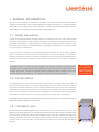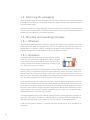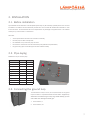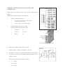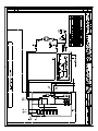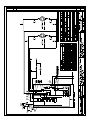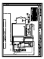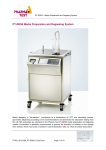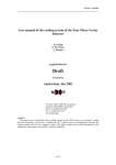
1
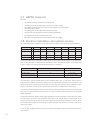
Ground source heat pumps since 1983 As Long As the Sun Exists Let Mother Earth Heat Your Home USER MANUAL LÄMPÖÄSSÄ V 7.0 — 30.0 LÄMPÖÄSSÄ 3/2010 1 2 Ground source heat pumps since 1983 Contents 1. GENERAL INFORMATION 5 1.1. Safety precautions 5 1.2. Transportation 5 1.3. Installation area 5 1.4. Removing the packaging 6 1.5. Structure and operating principles 6 1.5.1. Structure 6 1.5.2. Operation 6 2. INSTALLATION 7 2.1. Before installation 7 2.2. Pipe-laying 7 2.3. Connecting the ground loop 7 2.4. Filling and de-aeration of the ground loop 8 2.5. Heating connection 9 2.6. Domestic water connection and circulation of water 9 2.7. HEPAC check list 10 2.8. Electrical installation and outdoor sensors 10 2.9. Electricity check list 11 2.10. Startup 11 3. USER INFORMATION 12 3.1. Lämpöässä settings 12 3.1.1. Settings for heating curve 12 3.1.2. Settings 13 3.1.3. Measurements 15 3.2. Care and maintenance 16 3.3. Troubleshooting 16 4. TECHNICAL SPECIFICATIONS 18 4.1. Chart 18 4.2. Space requirements 18 5. WARRANTY 19 6. APPENDIX 19 3 4 Ground source heat pumps since 1983 1. GENERAL INFORMATION We thank you for your confidence in our products and congratulate you on making an excellent choice! You have selected a long-lasting and environmentally friendly Lämpöässä geothermal heat system. We hope that you will enjoy Lämpöässä’s heating system which will give you peace of mind for decades. It is important to read the user and maintenance instructions carefully. Please retain this manual for future use and reference should problems occur. 1.1. Safety precautions To ensure the Lämpöässä geothermal heat system operates in a trouble-free manner and in order to obtain the best operating efficiency, the system must be transported and installed in accordance with the instructions provided by the manufacturer. After installation is complete, the check list provided must be reviewed in order to minimise any installation errors. The manufacturer shall not be responsible for any breakages of equipment which is not installed correctly or any costs incurred as a result of this. The pipe and electrical installations for the Lämpöässä geothermal heating system can only be installed by qualified persons. If problems occur during installation, we recommend that you contact your retailer or our maintenance department. The telephone number for the maintenance department can be found in the documents delivered with the Lämpöässä heat pump. Electrical connections for the installation of the Lämpöässä may only be set up by qualified electricians. In Lämpöässä V models – to prevent a compressor breakdown – the compressor and water in the storage tank must be preheated for 6 hours before the heat pump is started for the first time. Press the motor protective switch down and switch on the power. This stops the compressor starting and enables the electrical immersion to heat up the compressor and water in the storage tank. The compressor can be started after 6 hours of preheating. The warranty of the Lämpöässä V compressor is not valid if preheating is not carried out. 1.2. Transportation The Lämpöässä heat pump must always be transported in a vertical position. If tilting the system is unavoidable, for example to pass through a doorway, it may only be tilted to the left side or back as seen from the front of the heat pump. If the required angle exceeds 45°, the cold unit must be detached during tilting. The unit may be moved from beneath using a forklift, for example. Please note! As the centre of gravity of the heat pump is on the left as seen from the front, and not in the middle due to the placement of the water tank but on the left as seen from the front, the forklift must be placed on the left side of the pump. Do not go underneath the equipment while it is being lifted! A transportation platform is fastened on both sides of the heat pump using screws. When the screws on the platform are removed, the adjustable feet used for final installation can be found inside. 1.3. Installation area We recommend that the Lämpöässä geothermal heat pump be installed in a warm space which has a floor drain. During installation and when filling of the ground loop, some geothermal fluid mixture may be splashed on the floor. Glycol/water mixture can be used as well. The chosen area does not have to be fireproof. The floor must be able to withstand the weight of the heat pump carrying a full water tank (= dead weight + 400 kg). The floor must also be sufficiently even, because the heat pump must be as level as possible. Final adjustments can be made using the adjustable feet underneath the equipment. 5 1.4. Removing the packaging Remove the plastic wrapping and corner padding from around the product. Check that the heat pump has not suffered any damage during transportation. If the heat pump is found to be damaged, the company which delivered the product must be immediately notified. Also check the contents of the delivery immediately. Your delivery should include 2 x flexible pipes, an outdoor sensor and a room sensor (latter item optional). Please ensure that you notify us within 5 days if all the additional equipment specified in the order confirmation is not included in the delivery. 1.5. Structure and operating principles 1.5.1. Structure The Lämpöässä geothermal heat system consists of a network of heat collection pipes, a geothermal fluid mixture circulating within the network and a geothermal heat pump unit. The geothermal heat pump unit consists of an integrated water tank, compressor, evaporator, condenser and a refrigerant circulating inside the pump. The heat collection fluid in the ground loop and the refrigerant do not mix at any stage of the process. 1.5.2. Operation The Lämpöässä heat pump transfers heat from the ground, water system or Ground source heat pump a bore well. Of the total thermal energy required for heating, Lämpöässä collects more than 70% from natural sources. Less than 30% of the electri- Compressor Earth 3/4 Heat 4/4 Heating+ dhw Electricity 1/4 cal energy is required for the collection of thermal energy. This energy is used to run the various components in the system. Evaporating Condensing The heat collection pipe is a plastic pipe (PEM 40/10) with a water and ethyl alcohol or glycol-water mixture circulating inside. It is placed 1-1.2 metres deep in the ground or at least 3 metres deep in water. The bore well is normally 100200 metres deep with a diameter of 140-165 mm. The heat pump is used in the transfer of heat from the water and ethyl alcohol mixture. Approximately three degrees of heat is transferred into the refrigerant circulating inside the heat pump, after which the geothermal fluid returns to the ground loop to heat up again. Heat is transferred from one fluid to another in the evaporator, in which the refrigerant evaporates thanks to the low suction head of the compressor. This binds the heat from the geothermal fluid with the help of a disk thermal exchanger. The pressure of the gaseous refrigerant is increased using a compressor which makes the temperature of the refrigerant rise. The heat contained in the gas is transported in the condenser to heat the water in the water tank and thus produce hot water for use. As the heat is transferred, the gas turns into fluid once again and is carried back through a dehumidification filter and an expansion valve to circulate. The Lämpöässä geothermal heat pump is suitable for producing hot water and heating single-family households, terraced houses, offices, hotels and industrial halls. Heat distribution can be implemented using floor heating with circulating water, water-filled radiators or the circulation of hot air. Floor heating has the best operating efficiency. In order to ensure trouble-free operation, all Lämpöässä heat pumps have been test-run, set up and tested by the manufacturer. 6 Ground source heat pumps since 1983 2. INSTALLATION 2.1. Before installation Pipe assemblies for the installation of the Lämpöässä system may only be installed by qualified persons. The unit must be installed in accordance with the instructions provided and a check list must be reviewed after installation in order to minimise errors. The manufacturer shall not be responsible for any breakages of equipment which is not installed correctly or any costs incurred as a result of this. Check that • all the required hoses and sensors are included in the delivery • the heat pump has been correctly fitted • the assemblies on top of the heat pump are intact • the fuse size is correct for the main fuse and the heat pump (see technical specifications) • the ground loop pipes and the feed pipes have been installed correctly 2.2. Pipe-laying Assemblies on top of the heat pump: Assemblies V7.0 - V15.0 V20.0 - V30.0 Domestic water, cold Nr 1: Cu 22 Nr 1: Cu 22 Domestic water, hot Nr 2: Cu 22 Nr 2: Cu 22 Auxiliary group, flow Nr 3: 1” Nr 3: 1” 2 1 6 9 Auxiliary group, return Nr 4: 1” Nr 4: 1” Heating circuit 1, return Nr 5: Cu 28 Nr 6: Cu 42 Heating circuit 1, flow Nr 6: Cu 28 Nr 5: Cu 42 Heating circuit 2, flow Nr 7: Cu 28 Nr 7: Cu 42 Heating circuit 2, return Nr 8: Cu 28 Nr 8: Cu 42 Lift hook / Expansion Nr 9: 3/4” Nr 9: 1” Electrical immersion Nr 10 - 10 4 3 5 8 Sensor Electrical supply 7 2.3. Connecting the ground loop The assemblies Cu 28 (V7.0-15.0) /Cu 35 (V20.0-30.0) for the ground 1 2 loop are located in a compartment behind the unit as shown. The ground loop assemblies are connected to the ground loop using a flexible assembly pipe. Care must be taken when attaching the assembly pipe. 1. Heat collection, in 2. Heat collection, out 7 2.4. Filling and de-aeration of the ground loop Equipment required for the filling and deaeration of the ground loop: • mixing tank, 60 litres • a submersible pump fitted with a filter, lifting height approximately 30 m • water and ethyl alcohol, or glycol-water mixture (1:1) with a frost resistance of -17 degrees Celsius • 2 x textile hose 1”, length approx. 3 m • 2 x joint 1/2” (female) THE FILLING AND DE-AERATION PROCESS Please check that the ground loop has been correctly connected (see “Connecting the ground loop” section) and that the compressor in Lämpöässä V models has been preheated (see ”Safety precautions” section). 1. remove the styrofoam packaging protecting the group of fill valves 2. detach the expansion tank from the foremost ball valve 3. close the shut-off valve at the back of the group of fill valves 4. open the foremost shut-off valve in the group of fill valves 5. attach the submercible pump textile hose to the foremost ball valve in the group of fill valves and open the ball valve 6. attach a textile hose from the ball valve at the back of the group of fill valves to the filling container and open the valve 7. fill the container with a geothermal fluid mixture (ethyl alcohol water or glycol with a frost resistance of -17 degrees Celsius) 8. turn on the submersible pump 9. add the water and ethyl alcohol mixture to the mixing container until no more fluid can enter the pipes 10. keep the submersible pump running until the fluid is clear and no gurgling can be heard from the pipes. Please note! Deaeration usually takes several hours and helps ensure that all the air is removed from the system and that there are no malfunctions once the system is started. LEAVE NO PRESSURE IN THE NETWORK! 11. open the shut-off valve at the back of the group of fill valves 12. close both ball valves 13. remove the filling hoses 14. fasten the expansion tank back in its place in the foremost ball valve in the group of fill valves 15. remove the shut-off valve on the expansion tank 16. fill 3/4 of the expansion tank with the geothermal fluid mixture 17. fasten the shut-off valve to the expansion tank 18. open the foremost shut-off valvae in the group of fill valves 19. remove and clean the net strainer on the mud separator Filling and deaeration have now been completed. PLEASE NOTE! Once the heat collecting pipes have been placed in a bore well, we would advise users to switch the positions of the textile hoses in the group of fill valves during filling and deaeration. This increases the efficiency of the pipes. 8 Ground source heat pumps since 1983 Deaeration can be made more efficient by using the pump on the ground loop of the heat pump. The circulation water pump on the ground loop and the submersible pump used in the deaeration are then connected in series. The circulation water pump on the ground loop is started as follows: 1. ensure that the red switch on the protective switch for the compressor motor has been pressed down (this stops the compressor activating) 2. turn on the power at the mains 3. turn on the control current 4. turn the switch on the ground loop pump to the left (the pump on the ground loop in continuous use) Before starting the ground loop pump, fill the filling hose on the suction side with a water and ethyl alcohol mixture using a submersible pump or, for example, a watering can to ensure the ground loop pump does not run empty. In models 7–10.5, a submersible pump should always be used for deaeration, while in models 13–15, the deaeration can also be carried out using the ground loop pump on the heat pump only. We do, however, recommend the use of an external pump to speed up deaeration and make it more efficient. 2.5. Heating connection The pipes in the heating network are connected to the thermal heat pump using either textile hoses (network of radiators) or using a fixed piping network (floor heating network). These connections stop sound from passing into the pipes. All heating connections (for example, a heating radiator for an air conditioner or a heated towel rail) must be made to the heat piping. When the network piping on the is in place, filling may commence. The pipes in the network are filled with water. Please note! If renovating, ensure that the heat distribution piping has been properly rinsed before connecting the heat pump. Filling a heating system fitted with a pressure gauge: • open the fill valve on the heating network • fill the piping with water • deaerate the piping through the water tank • fill and deaerate the network until all the air has been removed and leave the pressure at 1–1.2 bar 2.6. Domestic water connection and circulation of water Complete the piping connections according to the piping connections diagram in section 2.2. The circulation water pump is installed on the input side of the heat pump. The mixing valve is fitted to the hot water pipe in order to prevent burns. The overflow pipe is joined to the floor drain as instructed or to an overflow funnel if the distance to the floor drain is more than two metres. The overflow funnel must be directed down towards the floor drain. The backpressure valve is fitted to the cold water joint on the input side. We recommend that the a timer be installed to control the circulating water pump for running water in so that the pump only operates when water is needed. Without a timer control, the heat pump will have a considerably higher operating time ratio. 9 2.7. HEPAC check list Check that • the connections are tight and there are no leaking valves • the expansion tank on the heating system and fill side is properly installed • the overflow pipe on the shut-off valve and the pressure gauge on the heating system have been properly installed • the heating system has been filled and deaerated appropriately • the ground loop has been installed, filled and deaerated appropriately • the foremost valve is open and the rear valve is shut • the unused solar assemblies on top of the heat pump have been plugged 2.8. Electrical installation and outdoor sensors Only qualified electricians are permitted to carry out electrical work on the heat pump according to general regulations. Device V 7.0 V 9.0 V 10.5 V 13.0 V 15.0 V 20.0 V 30.0 Electrical connection 400V 3N~ 400V 3N~ 400V 3N~ 400V 3N~ 400V 3N~ 400V 3N~ 400V 3N~ 3 x 16 (20) 3 x 16 (20) 3 x 16 (20) 3 x 20 3 x 25 Slow Slow Slow Slow Slow Fuse size (part) A Electrical connection Fuse size A 3 x 16 Slow 3 x 16 Slow 230V 1N~ 230 1N~ 230 1N~ 25 Slow 32 Slow 32 Slow The Lämpöässä heat pump is connected to a 400 V (50 Hz) or 230 V (50Hz) electrical network. The Lämpöässä heat pump has been fitted with an integrated electrical switchboard to which is permanently powered. A plastic-coated wire is used as a supply line. This wire travels to the master switch in a casing pipe. DEVICE TERMINAL BLOCK NUMBER CONDUCTOR TYPE Outdoor sensor TMO T1 2 X 0.7 mm2 Room sensor TMR T3 2 X 0.7 mm2 Size of the feeder cable * (part) 5 X 2.5 mm2 (6.0 mm2) * If installation conditions require long cabling, a 5 x 6 mm2 cable should be used in models V 10.5-30.0. The master switch must be installed before any other installation takes place. In order for the outdoor sensor to recognise weather conditions as effectively as possible, it is very important that it be placed in the correct location. The outdoor sensor should be placed on the north-western or northern side of the building to avoid the effects of the morning sun. If the sensor cannot be placed as recommended, ensure that it is protected from direct sun light. The sensor is placed approximately 2/3 of the way up the wall of the building near the corner. A sensor should not be placed under a roof, in a place protected from the wind or over a vent, doors or windows where the temperature is not the normal outdoor temperature. In order for the room sensor to detect average indoor temperatures as reliably as possible, it must be placed in a central and open location, for example a hallway between several rooms or the staircase. String a bipolar electrical line (at least 0.5 mm2) from the heat pump to the room sensor. Position the room sensor approximately 2/3 of the way up the wall. Connect the room sensor lead to the heat pump. Please note! Leads must be correctly connected in order for the heat pump to operate. In order to obtain the best results, the room sensor and leads can be tested in diffirent locations before being permanently installed. 10 Ground source heat pumps since 1983 2.9. Electricity check list Check that • all phases going to the switchboard are in the correct phase sequence • the fuse size is correct (slow) 2.10. Startup Before startup, check that: • the heating system has been connected, filled and deaerated appropriately • the ground loop has been installed, filled and deaerated appropriately • electrical connections have been made appropriately and the outdoor sensor (room sensor, optional accessory) has been installed Possible problems during startup Problem Cause Solution Fuses always blow when the You are using the wrong type of fuse. Check that the fuse is automatic: C or D/ceramic compressor is being started. fuse: SLOW or with a snail icon. Temporary connections at the site are causing an Reduce load. overload on the fuses. The ground loop pump does The regulator may not be getting any power. not start. Check the regulator fuse. The regulator is not authorised to start the pump. Check the measured/set values. The ground loop pump is rotating in the wrong Switch the location of the two phases. direction. Shut-off valves are in the fill position. Check that the deaeration and fill valves are in the ‘closed’ position and that the intermediate valve is open. The compressor runs for a There may still be air in the ground loop. Deaerate the ground loop. pressure switch goes off. There may be a leak in the refrigerant loop. Contact the manufacturer. The fluid level in the ground There is a leak in the system (the smell of ethyl Check the condition of valves in the deaeration loop fill container drops alcohol is strong), there is a leak in the ground group on the air lock and the shaft seal on the suddenly after startup. loop or there is still air in the ground loop. ground loop pump and, if possible, the ground little while and the steam loop extension joints, or deaerate. Thermal relays go off when The compressor or the ground loop pump is short- Check electrical connections. starting. circuited or one of the phases is not activated. Fuses in the master switchboard of the building Check and replace fuses as required. are faulty. 11 3. USER INFORMATION 3.1. Lämpöässä settings Information in this section has been compiled from the Lämpöässä 203/GT Manual, which, in addition to the following, includes more detailed information on the various functions and detailed reading(s). 3.1.1. Settings for heating curve The single most important element for a stable room temperature is a characteristic heating curve of exactly the correct shape. The shape of the heating curve depends on three different values which determine the temperature of the water going to the heater when outdoor temperatures are -20°C, 0°C and +20°C. The Lämpöässä 203/GT regulator prevents the setting of an incorrectly shaped heating curve. It automatically suggests an adjustment. Press ESC until the display no longer changes. You are in the ‘Selection’ display. Press OK. You can move from one regulating circuit to another using the browser button. 12 Ground source heat pumps since 1983 Use the browser button to move the cursor to “Heating curve”. Press OK. Press OK. Use keys – or + to set the value for the output water when the outdoor temperature is -20°C. Press OK. Press OK. Use keys – or + to set the value for the output water when the outdoor temperature is 0°C. Press OK. Press OK. Use keys – or + to set the value for the output water when the outdoor temperature is +20°C. Press OK. Press ESC to exit. 3.1.2. Settings The Lämpöässä regulator is controlled using set values. The available set values depend on the sensor connections and geothermal heating options. Browsing the set values and changing them is done as follows: Press ESC until the display no longer changes. You are in the ‘Selection’ display. Press OK. You can move from one regulating circuit to another using the browser button. Use the browser button to move the cursor to “Settings”. Press OK. Changing the set values for the heating regulation circuit: Use the browser button to move the cursor to the setting you wish to change. Press OK. Use keys - and + to change the value. Press OK. Press ESC to exit. 13 The most common set values: Set value Setting range Room temperature 21.5°C 5–45°C Effect of night reduc- 0°C 0–35°C 15°C 5–95°C Comment Room temperature set value set by the user. During the night reduction, the regulator uses the calculated room temperature value. tion Minimum limit The amount of night reduction for output water activated using a timer, an external home/away switch or GSM control. The lowest permitted temperature for output water. Setting the minimum level of floor heating for tiled floors to 20–25°C ensures comfortable heating and the evaporation of moisture in the summer. Maximum limit 45°C 15–125°C The highest permitted temperature for output water. The maximum limit can be used to prevent temperatures that are too high (for example, caused by an error when setting the control characteristic) as well as possibly damage to the piping and surface materials. For floor heating, set at 35–40°C. Room compensation 1.5°C 0–7.0°C ratio If the room temperature diverges from the set value, the room compensation function adjusts the temperature of the output water. For example, when the compensation setting is at 4, the function reduces the temperature of the output water by 6°C after an increase of 1.5°C in room temperature (4 x 1.5°C = 6°C). Autumn drying 1°C 0–15°C The autumn drying function automatically increases the temperature of output water in the autumn for 20 days. The function is switched on when the average daily temperature has been over 7°C for at least 20 consecutive days and then drops below 7°C. The function is on for the following 20 days when the average daily temperature is below 7°C. The set value for the function shows how much the function increases the temperature of the output water. The factory setting is 1°C. Closing the valve for 20°C 5–50°C the summer The outdoor temperature limit at which the regulator closes the valve for regulating circuit L1. Regulating circuit L2 is often used for heating humid spaces. Humid spaces also need to dry in the summer, so the valve in regulating circuit L2 is not closed. Minimum limit for the 55°C 5–75°C If the temperature for the upper water tank (measurement 9) falls below the set temperature for the value, the measurement allows the compressor to start. The compressor will start upper part of the water provided the temperature in the lower tank (measurement 10) does not prevent tank Minimum limit for the it doing so. 45°C 20–50°C temperature for the lower (measurement 9) and the lower water tank (measurement 10) fall below the part of the water tank Water for use The regulator starts the compressor if the temperatures of the upper water tank minimum limit. 55°C 5–80°C Set value for water for use. (Recommendation > +55°C) The operating efficiency of the device may vary due to the geographical location. The annual operating efficiency reaches its optimal point when the water tank temperature is maintained at the correct level. The factory setting for the minimum set value for the lower part of the water tank is +45°C (30–50). The factory setting for the minimum set value for the upper part of the water tank is +55°C (5–55). As a rule, the set values of the water tank are kept as low as possible to allow for the best annual operating efficiency possible. During the winter, when the need for heating is great, the set value for the lower part of the water tank should be determined in relation to the temperature of the output water. The temperature of the upper part of the water tank increases after a long period of use and the threshold value for the compressor to run is 95°C. This is due to the super-heating properties of the water tank structure. This is why a mixing valve for hot water must be used in order to prevent any risk of burns from the scalding hot water. The compressor is controlled, as a rule, according to the minimum setting of the lower part of the water tank. During the summer, when there is no need for heating (with the exception of humid rooms), the compressor is seldom on and there is not enough super-heating to produce hot water for use. In this case, the minimum temperature of the upper part of the water tank can be maintained at +55°C and the compressor will be controlled according to the minimum temperature of the upper part of the water tank. 14 Ground source heat pumps since 1983 3.1.3. Measurements The Lämpöässä 203 regulator can take 14 concurrent readings (11 NTC readings and 2 digital inputs). The display only shows the readings related to the regulator. There are 2 free readings. Operating instructions: Press ESC until the display no longer changes. You are in the ‘Menu’ screen. Pressing the + key in this screen, the regulator shows you all the readings one by one and then returns to the standard display screen. The readings can also be browsed in the ‘Measurements’ screen. Press OK. Use the browser button to move the cursor to ‘Measurements’. Press OK. Browsing the readings: Use the browser button or the + key to browse through various readings on the display. The ‘Measurement’ screen shows all the readings for all the regulating circuits. Press ESC to exit the ‘Measurements’ screen. Each sensor has its own typical reading range. When the reading value is outside of this range, the display shows a + or - sign to show whether the reading value is above or below the range. If the sensor is faulty, the regulator sounds an alarm and the reading value shows ‘err’. Terminal Reading Information on the reading Reading range 1 Outdoor temperature Outdoor temperature -50–+50°C 2 L1 Output water The temperature of output water in regulating circuit 1 0–130°C 3 L1 Room Room temperature in regulating circuit 1 (room compensation) -10–+80°C 5 L2 Output water The temperature of output water in regulating circuit 2 0–130°C 6 Measurement 6 Free temperature reading that can be renamed -10–+80°C 6 L2 Room Room temperature in regulating circuit 2 (room compensation) 6 Wind Wind speed (% of the sensor reading range) 6 Sun Amount of light (% of the sensor reading range) 7 LV Output water The temperature of output water for use 0–130°C 8 LV Circulating water The temperature of return water from use -10–+80°C 9 Water tank, upper part The temperature of the upper part of the water tank 0–+130°C 10 Water tank, lower part The temperature of the lower part of the water tank 0–+130°C 11 Measurement 11 Free temperature reading that can be renamed 0–+130°C 11 Hot gas The measured temperature of hot gas from the compressor. Please note! block Measurement 11 and the hot gas reading are alternative readings. Compressor time The total running time of the compressor in hours Electric resistor time The total running time of the electric resistor in hours Motor L1 Setting for valve motor in regulating circuit L1 Motor L2 Setting for valve motor in regulating circuit L2 Motor LV Setting for valve motor in regulating circuit for water for use 15 3.2. Care and maintenance The Lämpöässä heat pump is an easy-care heating system. It requires no regular maintenance. If the installation is carried out carefully and in accordance with the instructions provided, there is usually no need for maintenance. The fill container inside the geothermal heat pump should be checked every couple of weeks during the first few months and afterwards approximately once a month for the first year of use thereafter. 3.3. Troubleshooting If an alarm sounds, we always recommend that you first check that the regulator does not have the 5-minute compressor running prevention enabled. The facility can be overridden by turning the master switch to 0 and back. The geothermal heat pump is controlled according to two measured values: the measured value at the bottom and at the top of the water tank. A minimum value is determined for each set value in the “Set values” section. In practice, consumption of hot water also starts the compressor. The lower the minimum set value for the lower part of the water tank, the more economical the use of the system. However, it is important to note when determining the set value that values which are too low will reduce the amount of hot water available. Further information is available in the section of the Lämpöässä instructions entitled, “Full power geothermal heating 201/GT and 203/GT”. Problem Possible cause The compressor does not The water tank temperature is adequate and in accordance No action required. Solution start with the regulator. The compressor has been stopped for less than 5 minutes. No action required. Fuse problem. Check the condition of the fuses in the master switchboard. The compressor does not The protection switch for the motor has gone off. Press the protection switch for the motor. start and the regulator OR OR display reads: “divergence The suction pressure switch on the pressure switch has Set off the switch. alarm reading 4 compressor gone off. operation”. No text is visible on the The device is not getting any power. regulator. Check that the control current and master switch are on. A fuse has blown. Replace the fuse (125 mA). The display is broken/the circuit board of the regulator is Contact maintenance. faulty. Thermal relays go off The protection switch for the motor goes off if the immediately when power is equipment is short-circuited or one of the phases is not on. Contact an electrician. switched on. Fuses in the master switchboard of the building are faulty. Check the condition of the fuses and replace as required. Regulator display reads: You have attempted to change the settings in maintenance Special settings for maintenance Enter code mode. mode are not required for normal use. Set values for temperatures can be set in normal mode. The system does not produce A sudden drop in outdoor temperature may temporarily enough heat cause inadequate heating power in new buildings, because No action required. moisture contained in the structure takes up a lot of heat when it dries. During the first year, the ground loop may not produce heat No action required. at full power because the earth around the ground loop pipes has not yet become more solid. 16 Ground source heat pumps since 1983 The set value and measured A maximum limit has been used for the set values. value for the regulator do not match. A spiking over-voltage caused by a lightning strike has The regulator must be replaced (not caused a fault in the condenser, causing the temperature to under warranty). drop from the actual values. The regulator motor has been set on manual and the regulation does not take place. In the summer, the temperature in the room where the No action required. heat pump is located may rise to up to 30 degrees Celsius. In these cases, the temperature sensor for the output water is reading the air temperature instead of the temperature for the output water. The compressor is on all the A lot of heat is needed, for example the outdoor tempera- time or for long periods of ture is very low or the structure is drying during the first time. year’s use of the building. No action required. Lack of refrigerant. Can be detected from bubbles in the Contact a refrigeration supplier or liquid container even after some minutes of use. maintenance. The processor/software on the regulator is faulty. Turn off the control current switch for 10 seconds and turn it back on. If turning off the power does not help, contact maintenance. If the above instructions do not help, please contact your local Lämpöässä dealer. PLEASE NOTE! The warranty shall be subject to the existence of an appropriately completed and issued warranty certificate and a certificate signed by the user stating that the mechanic instructed the user on how to operate the equipment. 17 4. TECHNICAL SPECIFICATIONS 4.1. Chart Lämpöässä heat pump V 7.0 V 9.0 V 10.5 V 13.0 V 15.0 V 20.0 V 30.0 Dimensions width mm 900 900 900 1050 1050 1250 1250 depth mm 650 650 650 650 650 800 800 height mm 1900 1900 1900 1900 1900 1900 1900 Weight kg 430 435 440 490 495 600 630 Scroll Scroll Scroll Scroll Scroll Scroll Scroll 1400 1400 1400 1750 1750 2820 2900 Max length of ground loop m 300 300 300 500 500 500 500 Water tank capacity litres 420 420 420 520 520 750 750 Max pressure radiator bar 1.5 1.5 1.5 1.5 1.5 1.5 1.5 201 GT 201 GT 201 GT 201 GT 201 GT 201 GT 201 GT Priority relay Yes Yes Yes Yes Yes Yes No Supplied output 35/50°C * kW 7.9 / 7.2 9.9 / 9.0 11.4 / 10.6 14.2 / 13.1 16.7 / 15.3 20.64 / 18.93 31.18 / 28.92 Supplied input 35/50°C * kW 1.74 / 2.27 2.12 / 2.76 2.42 / 3.31 3.03 / 4.04 3.57 / 4.64 4.83 / 5.94 7.92 / 10.15 Start current A 28 33 37 45 52 88 159 Running current 0/35°C A 3.7 4.5 4.8 5.9 6.8 9.6 12.8 Running current 0/50°C A 4.3 5.1 5.8 7.1 8.2 11.1 16.0 Fuse size, Slow (part) A 3 x 16 3 x 16 3 x 16 (20) 3 x 16 (20) 3 x 16 (20) 3 x 20 Compressor Refrigerant g Heat regulator as standard Electrical connection 400V 3N~ 3 x 25 Electrical connection 230 V 1N~ Supplied output 35/50°C * kW 7.55 / 7.05 9.45 / 8.85 11.2 / 10.45 Supplied input 35/50°C * kW 1.66 / 2.17 2.18 / 2.81 2.42 / 3.22 Running current 0/35°C A 8.3 11.9 11.9 Running current 0/50°C A 10.3 14.2 15.2 Fuse size A 25 Slow 32 Slow 32 Slow * Ground collector 0°C 4.2. Space requirements The Lämpöässä heat pump can be positioned anywhere in a technical or utility room. The heat pump does not require much more floor space than its external dimensions. All Lämpöässä geothermal heat pumps are 1.9 metres in height. Approximately 0.4 metres of space must be reserved for the assemblies on top of the heat pump. This should be taken into account when placing the heat pump in a low room, such as a basement. The Lämpöässä geothermal heat pump should be installed in a warm, insulated space which has a floor drain, because some ground loop fluid may be splashed on the floor when the ground loop is filled. The chosen area does not need to be fireproof. mm V 7.0 18 V 9.0 V 10.5 V 13.0 V 15.0 V 20.0 V 30.0 A 50 50 50 50 50 50 50 B 50 50 50 50 50 150 150 C 200 200 200 200 200 500 500 O 700 700 700 700 700 950 950 X 1200 1200 1200 1200 1200 1800 1800 Y 1300 1300 1300 1300 1300 1500 1500 5. WARRANTY Suomen Lämpöpumpputekniikka Oy offers a two- (2) year warranty with the Lämpöässä V geothermal heat pumps it manufactures. The manufacturer shall not be responsible for any breakages of equipment which is not installed correctly, any brekages of equipment which is installed contrary to the instructions provided, or any costs incurred as a result of these actions. The warranty shall be subject to the existence of an appropriately completed and issued warranty certificate and a certificate signed by the user stating that the mechanic instructed the user on how to operate the equipment. 6. APPENDIX Current control relays adjusting and connecting, device V 7.0 — 30.0 Connection diagram, device V 7.0 — 15.0, 1 circuit Connection diagram, device V 7.0 — 15.0, 2 circuit Connection diagram, device V 20.0, 1 circuit Connection diagram, device V 20.0, 2 circuit Electrical diagram, device V 7.0 — 10.5, 1N~ Electrical diagram, device V 7.0 — 10.5, 3N~ Electrical diagram, device V 13.0 — 15.0, 3N~ Electrical diagram, device V 20.0 — 30.0, 3N~ CURRENT CONTROL RELAYS ADJUSTING AND CONNECTING These values are default values you can get change those values. Relays have to adjust always case sensitive. 1. 2. Choice correct current area • Turn switch 2 position ON (when main fuse are less than 50A) • Others switchs 1,3-6 position OFF. Adjust hyseresis current % and delay srews from the front (main fuse 25A) • Hysteresis 21 • Current 25 - 28 % • Delay 1s HYSTERESE CURRENT DELAY SWITCHES ARE UNDER THE COVER • Relay need external power 24-240 V/AC. • External power connect connectors A1 and A2. • Connectors 15 and 16 connect ground heat pump and those cut power on the immersion heaters those line what current limit are exceed. • Every line must be lead through to relays. • L1 1- relay • L2 2- relay • L3 3- relay LÄMPÖÄSSÄ IS A TRADEMARK OF SUOMEN LÄMPÖPUMPPUTEKNIIKKA OY. ALL RIGHTS RESERVED. SUOMEN LÄMPÖPUMPPUTEKNIIKKA OY PO BOX 49 FIN-62101 LAPUA WWW.LAMPOASSA.COM R