1
ALPHANUMERIC
DISPLAYBOARD
µTAB PI X
AND
SELF-TIMING SYSTEMS
User Manual
Version 3.0
Microgate S.r.l.
Via Stradivari, 4
I-39100 BOLZANO - ITALY
http://www. micro gate.it
µTAB Displayboard and Self-Timing Systems
User Manual
2
µTAB Displayboard and Self-Timing Systems
User Manual
3
INDEX
1
ALPHANUMERIC DISP LAYBOARD µTAB (MICROTAB ) .................................................. 5
1.1
C ONT RO L P ANE L ............................................................................................................. 6
1.2
C ONNEC T IONS ................................................................................................................ 7
1.3
P OWE R S UPP LY ............................................................................................................... 8
1.3.1 Battery Recharge ........................................................................................................ 8
1.4
M ODULA R S YST E M ........................................................................................................ 10
1.4.1 µTAB Master and Slave ............................................................................................. 10
1.4.1.1
1.4.1.2
1.4.1.3
µ TA B M AS TER an d µ TA B SLA VE Connection ................................................................. 10
Disp lay o f 2 o r m o re lin es ................................................................................................. 12
Use o f µ TA B MAS TER as µ TA B S LAVE .......................................................................... 12
1.5
P ROPO RT ION A L F ONT .................................................................................................... 13
1.6
VIA R AD IO S YST E M ....................................................................................................... 13
1.7
µ TAB F IR M WA R E .......................................................................................................... 14
1.7.1 Firmwar e upd ating ................................................................................................... 14
2
P ROGRAMS ...................................................................................................................... 15
2.1
P ROG RA M 0 (N OR MA L ) .................................................................................................. 16
2.2
P ROG RA M 1 (M EM OR Y P ROG RA M ) .................................................................................. 18
2.3
P ROG RA M 2 (C HRONO M ET E R ) ......................................................................................... 19
2.4
P ROG RA M 3 (S PEE DM ET E R ) ............................................................................................ 20
2.5
P ROG RA M 4 (C OUNT DO WN ) ............................................................................................ 23
2.6
P ROG RA M 5 (I NT E RNA L C LOC K ) ..................................................................................... 25
2.7
P ROG RA M 6 (I NT E RNA L C LOC K AND D AT E )...................................................................... 26
2.8
P ROG RA M 7 (L A P C HRONO M ET E R ) .................................................................................. 27
2.9
P ROG RA M 9 (T EST ) ....................................................................................................... 28
2.10 P ROG RA M 10 (S E LF T IM ING ) .......................................................................................... 29
2.10.1
Starting Coin Box.................................................................................................. 29
2.10.2
Finish d isplayboard .............................................................................................. 29
2.10.3
Printer ................................................................................................................. 30
2.10.4
Parallel automatic timing systems .......................................................................... 30
2.10.5
Operation ............................................................................................................. 30
2.10.6
Paramet ers setting ................................................................................................ 31
2.10.7
Default value of ed itable parameters ...................................................................... 33
2.10.8
Some suggestions .................................................................................................. 33
2.11 P ROG RA M 11 (P ARA LLE L S E LF T IM ING ) .......................................................................... 34
2.11.1
Connections .......................................................................................................... 34
2.11.2
Operation ............................................................................................................. 34
2.12 D EFA ULT VA LUE S OF ED IT A B LE PA RA MET E RS ................................................................... 35
3
APP ENDIX ........................................................................................................................ 36
3.1
A PP END IX A ................................................................................................................. 37
3.1.1 µTAB Serial Frame – Self Timing .............................................................................. 37
3.1.1.1
3.1.1.2
3.1.1.3
3.1.1.4
3.1.1.5
3.1.1.6
3.1.1.7
3.1.1.8
3.1.1.9
3.1.1.10
3.1.1.11
3.1.1.12
3.1.1.13
3.1.1.14
3.1.1.15
Date d isp lay ..................................................................................................................... 38
Tim e sett in g sen sit ive to b reak .......................................................................................... 38
Tim e sett in g n o t sen sit ive to b rea k .................................................................................... 38
Bre ak sett in g (b r eaks th e ex ecution of follow ing com m ands) ............................................. 38
Date sett in g ...................................................................................................................... 39
In tern al c lo ck t im e sett in g (Rea l Tim e Cloc k) .................................................................... 39
In tern al c lo ck t im e d isp lay (Rea l Tim e C lo ck ) ................................................................... 39
Ru nn in g str in g wr it in g ...................................................................................................... 39
Sto p ru n n in g strin g ........................................................................................................... 40
In tern al h ard ware p ro gram execut ion ................................................................................. 40
Self- Tim in g p r in te r str in gs ................................................................................................ 40
"Weak" disp lay b o ard reset (sen s it iv e to Brea k) .................................................................. 40
"Stro n g" d isp lay b o ard reset (not sensit ive to Brea k) .......................................................... 40
Fixed str in g wr it ing .......................................................................................................... 41
Param eters setu p ............................................................................................................... 41
µTAB Displayboard and Self-Timing Systems
User Manual
4
3.1.1.16
3.1.1.17
3.1.1.18
3.1.1.19
3.1.1.20
Disp lay of set t im e ............................................................................................................ 42
Pro gram start .................................................................................................................... 43
Pro gram en d ..................................................................................................................... 43
En try Po in t/Lab e l fo r lo o p s ............................................................................................... 43
Lo o p /Go to ........................................................................................................................ 43
3.3.1.1
3.3.1.2
3.3.1.3
3.3.1.4
3.3.1.5
Pro gram
Pro gram
Pro gram
Pro gram
No te fo r
3.2
A PP END IX B ................................................................................................................. 44
3.2.1 Connection of starting coin box ................................................................................. 44
3.3
A PP END IX C ................................................................................................................. 45
3.3.1 Version with interface for d ifferent chronometers ....................................................... 45
12 – Om ega OS M6 Chronom eter .......................................................................... 45
13 – Om ega Po we rt im e Ch ro n o m eter ................................................................... 45
14 – ALGE Ch ro n om eter ..................................................................................... 46
15 – Om ega/Lo n g ines 5005/ Ares Chronom eters.................................................... 47
co n n ectio n o f ch ro n om eters ................................................................................. 50
µTAB Displayboard and Self-Timing Systems
User Manual
5
1
ALPHANUMERIC
DISPLAYBOARD
µTAB (MICROTAB)
µTAB Displayboard and Self-Timing Systems
6
User Manual
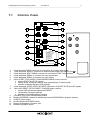
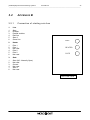
1.1
C ONTROL P ANEL
1
RADIO
2
SUPPLY
SELF-TIMING
SERIAL 1
SERIAL 2
3
5
4
START
STOP
6
7
(MODIFY
DIRECT CH.)
LOW
BATT.
START-STOP-LAP
INPUTS
LAP
RESET
8
9
(SETUP
DISCH./CH.)
FUSE
10
12
PROGRAMS
ADDRESS PROGRAM
0
1
2
3
4
5
6
7
9
= NORMAL
= MEMORY PROGRAM
= CHRONOMETER
= SPEEDMETER
= COUNTDOWN
= CLOCK
= CLOCK & DATE
= CHRONOLAP
= TEST
11
13
10 = SELF TIMING
11 = SELF TIMING PARALLEL
POWER
1
2
3
4
5
6
7
8
9
10
11
12
13
14
SPEAKER
14
5 pole Nucletron RADIO connector for connection of Linkgate radio system
7 pole Amphenol SUPPLY connector for external power supply and battery recharge
6 pole Amphenol SELF-TIMING connector for connection of Self Timing systems
6 pole Amphenol SERIAL 1 connector for serial input/output
6 pole Amphenol SERIAL 2 connector for serial output
Green START STOP (MODIFY DISCHARGE/CHARGE) button used for:
• manual START and STOP signals
• editing values of program settings (keep pressed down for fast forward)
• selection of battery discharge and recharge
6 pole Amphenol START-STOP-LAP INPUTS connector for START STOP and LAP signals
Yellow LAP RESET (SETUP DIRECT CHARGE) button used for:
• manual LAP signals and displayboard RESET
• confirmation of program settings
• selection of immediate battery charging
LOW BATTERY led to indicate battery status
Rotating ADDRESS switches for addressing lines and PROGRAM for program selection
FUSE for power supply
On/off displayboard POWER switch
External loudspeaker connection jack
Hardware programs legend
µTAB Displayboard and Self-Timing Systems
7
User Manual
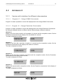
1.2
C ONNECTIONS
•
SUPPLY (7 pole Amphenol)
1
2
3
4
5
6
7
Ground
Ground
Ground
External supply input (8-25V)
External supply input (8-25V)
External supply input (8-25V)
Remote on/off input
•
SELF-TIMING (6 pole Amphenol)
1
2
3
4
5
6
START signal
COIN signal
PARALLEL signal
REDLINE signal
AUX signal
GREENLINE signal
•
SERIAL 1 (6 pole Amphenol)
1
2
3
4
5
6
SERIAL 1 - RS232 TX output
SYNC IN
SERIAL 1 - RS485 + RX input
SERIAL 1 - RS485 – RX input
Ground
SERIAL 1 - RS232 RX input
•
SERIAL 2 (6 poles Amphenol)
1
2
3
4
5
6
SERIAL 2 - RS232 TX output
SERIAL 1 - RS232 TX output
SERIAL 2 - RS485 + output
SERIAL 2 - RS485 - output
Ground
SYNC OUT
•
START-STOP-LAP INPUTS (6 pole Amphenol)
1
2
3
4
5
6
Start (NO - Normally Open)
+5V fixed, max 1A
Ground
LAP (NO)
STOP (NO)
Not used
7 pole Amphenol Connector
6 pole Amphenol Connector
µTAB Displayboard and Self-Timing Systems
User Manual
8
1.3
P OWER S UPPLY
Power can be supplied in three ways:
• By connecting the µTAB displayboard to the MICROGATE battery charger. In this way it is
possible to supply up to 6 mains supplied µTABs (1 MASTER and 5 SLAVES, see chap.1.4.1.1
µTAB MASTER and µTAB SLAVE on p.10) and to keep the batteries charged at the same time.
This guarantees perfect functioning also when the mains power supply is interrupted.
• By using the internal batteries of the displayboard. In this case autonomy is usually above 30
hours of continuous functioning (depending on the type of display used).
• By connecting the displayboard to any continuous current supply (whether steady or not)
between 10 and 30 Volts which is able to supply at least 30W peak power and about 2W
average power. A car battery guarantees several days’ autonomy.
Important note: the adaptor ACC062 for the µTAB displayboard is not suitable for outdoor use.
Consequently Microgate does not accept any responsibility for damage to persons or things due to
incorrect use of the adaptor.
1.3.1
Battery Recharge
If the batteries are low, either the discharge/recharge or the immediate recharge procedure can be
carried out.
In the first case, the batteries are first discharged and only subsequently recharged. This allows the
batteries to maintain their original capacity over a long period.
To select discharge/recharge, keep the “START STOP (MODIFY CHARGE/DISCHARGE)”
button on the control panel pressed down for at least 2 seconds with the displayboard
switched off after connecting an external power source to the connector SUPPLY. The operation
will take from a minimum 7 hours to a maximum of about 10 hours, depending on the initial battery
charge level.
If you choose immediate recharge instead, the operation will last about 7 hours. However, although
this type of recharge takes less time, it should only be used in exceptional circumstances as it
shortens the life of the batteries.
To select immediate recharge, keep the yellow “LAP RESET (SETUP DIRECT CHARGE)”
button on the control panel pressed down for at least 2 seconds with the displayboard
switched off after connecting an external power source to the connector SUPPLY.
In both recharge modes it is possible to interrupt the process by pressing the START STOP and
LAP RESET keys simultaneously.
µTAB Displayboard and Self-Timing Systems
User Manual
9
The LOW BATTERY led on the control panel tells you the battery charge status, the type of power
source used and the recharge operation status when the battery is being recharged.
EXTERNAL SUPPLY
STATUS
• Displayboard On or Off
• Batteries Charged
• Displayboard On or Off
• Batteries Discharged
LED LOW BATTERY
Green – Green – Pause
Green – Red – Pause
INTERNAL SUPPLY (BATTERY)
STATUS
• Displayboard Off
• Batteries Charged or Discharged
• Displayboard On
• Batteries Charged
• Displayboard On
• Batteries Discharged
LED LOW BATTERY
Off
Green – Pause – Green – Pause
Red – Pause – Red – Pause
CHARGE/DISCHARGE
STATUS
LED LOW BATTERY
Pause – Red – Pause – Red FAST
• Start of Discharging
Pause – Green – Pause – Green FAST
• Discharging Over–Start of Recharging
Green
• Recharging Over
DIRECT CHARGE
STATUS
• Start of Recharging
• Recharging Over
LED LOW BATTERY
Pause – Green – Pause – Green FAST
Green
µTAB Displayboard and Self-Timing Systems
10
User Manual
1.4
M ODULAR S YSTEM
1.4.1
µTAB Master and Slave
There are two types of alphanumeric µTAB displayboard:
• MASTER – the “intelligent” displayboard, fitted with a control panel in its side and internal
electronics, is used individually or in systems in which 2 or more displayboards are used.
• SLAVE – the “auxiliary” displayboard, without a control panel in its side, cannot be used
individually, and is used in systems featuring lines composed of two or more displayboards.
For example, a line of 45 characters (5 displayboards) is created with 1 MASTER displayboard
(the first on the left) and 4 SLAVE displayboards.
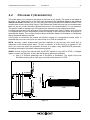
1.4.1.1
µTAB MASTER and µTAB SLAVE Connection
µTAB allows you to connect up to 3 displayboards (1 MASTER and 2 SLAVES), with the possibility
of displaying lines without any break between one µTAB and the next. The MASTER displayboard
“controls” the SLAVES through the connector DB25 situated on the control panel on the right (front
view).
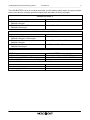
µTAB MASTER can be joined to µTAB SLAVE as explained below:
FRONT VIEW
A
A. Bring together the displayboards, keeping the µTAB SLAVE slightly tilted so that the pins at the
base of the displayboards are ready to be fitted into place.
B
BOTTOM VIEW
B. Align the µTABs sideways so that the pins on the SLAVE displayboard enter the slots provided
for them on the MASTER.
µTAB Displayboard and Self-Timing Systems
11
User Manual
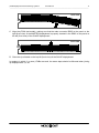
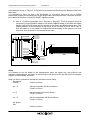
FRONT VIEW
C
C. Align the µTABs horizontally, making sure that the male connector DB25 on the panel on the
right (front view) of the MASTER displayboard is properly inserted in the DB25 on the panel on
the left (front view) of the SLAVE displayboard.
FRONT VIEW
D
D. Close the zip situated on the top left (front view) of the SLAVE displayboard.
In systems in which 3 or more µTABs are used, the same steps should be followed when joining
up displayboards 3,4, etc.
µTAB Displayboard and Self-Timing Systems
12
User Manual
1.4.1.2
Display of 2 or more lines
It is often necessary to use 2 or more µTABs to display 2 or more lines. This option is possible by
using only MASTERS (which allow 9 characters per line to be displayed) or by using lines
composed of MASTERS and SLAVES (up to a maximum 6 displayboards per line, therefore 54
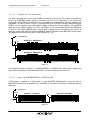
characters). As can be seen in Figure 1, the MASTER of the first line must be connected through
SERIAL 1 to the control device (using cable CAB011 if the control device is REI2, a 20m CAB010
cable and a 2m CAB001 cable if it is a PC), the SERIAL 1 of the second MASTER to the SERIAL 2
of the first (with cable CAB009) and so on for each subsequent line. In addition, the number of
each line must be set with the rotating ADDRESS selector situated on the MASTER control panel.
The Address of the first line will be 0, of the second line 1, etc.
PC - CHRONOMETER
SERIAL 1
SERIAL 2
MASTER 1: ADDRESS 0
MASTER 2: ADDRESS 1
SERIAL 1
F igure 1
In the example shown in Figure 1, 2 µTAB MASTERS e 2 SLAVES have been used to display the
name of the competitor, his position at the finish, his race number and his race time
1.4.1.3
Use of µTAB MASTER as µTAB SLAVE
µTAB makes it possible to connect two or more MASTER displayboards, using the first as
MASTER and the others as auxiliaries (or SLAVES) so that lines of more than 9 characters can be
displayed.
PC - CHRONOMETER
SERIAL 1
MASTER 1: COLUMN 0
SERIAL 1
SERIAL 2
F igure 2
MASTER 2: COLUMN 9
µTAB Displayboard and Self-Timing Systems
User Manual
13
As can be noted in Figure 2, the connector SERIAL 2 of the first MASTER is connected to the
SERIAL 1 of the one after. If 3 displayboards had been used, the SERIAL 2 of the second would
have had to be connected to the input SERIAL 1 of the third, and so on for each subsequent
displayboard. Finally, the SERIAL 1 of the first MASTER must be connected to a control device.
It is also necessary to set the “Column” value of the displayboards to indicate the position of the
first character of each displayboard in relation to the string to be displayed: the first displayboard
must be set with Column value at 0 (default value, see par. 2.1 Program 0 (Normal) on p.16), the
second with Column 9, the third with 18, etc.
However, the use of MASTER displayboards with SLAVES has a drawback: unlike a µTAB
SLAVE, a MASTER cannot be directly connected to the previous MASTER, thus making it
impossible to display strings without spaces between one displayboard and the next.
1.5
P ROPORTIONAL F ONT
Proportional fonts have:
• figures and punctuation of the same width
• letters of variable width
• space the same width as for figures
• “short” punctuation: ‘.’ corresponding to the character ASCII, ‘:’ corresponding to the
character ASCII
• “short” space the same width as for “short” punctuation and corresponding to the character
ASCII 255
“Normal“ Punctuation
“Short” Punctuation
1.6
VIA
R ADIO S YSTEM
Some
programs
for
the
µTAB
displayboard
(see
par.
2
Program on p.15) make it possible to use the Linkgate radio system connected through Decoder or
DecRadio to the RADIO connector situated on the µTAB control panel. Thanks to Linkgate it is
possible to transmit START STOP and LAP signals from a long distance and, in Program 0
(Normal), serial data.
For further information about the Linkgate system, consult the appropriate REFERENCE MANUAL.
In the following paragraphs, the possibility of using the via radio system will be indicated by a
section RADIO.
NOTE: To be able to use the Linkgate system in Program 2 (Chronometer), Program 3
(Speedmeter) and Program 7 (Lap Chronometer) the radio channel must be set in Program 0
(Normal) (see p.16) of the µTAB.
To be able to transmit control commands in Program 0 (Normal) via radio the velocity of the serial
communication must be set to “RAD.” within the settings of Program 0 (Normal) (see p.16).
µTAB Displayboard and Self-Timing Systems
User Manual
14
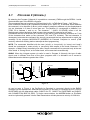
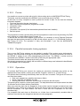
1.7
µ TAB
F IRMWARE
Every time it is switched on, µTAB displays the firmware version stored at that moment:
TIPO DI FIRMWARE VERSIONE DEL FIRMWARE
FIRMWARE TYPE
FIRMWARE VERSION
F igure 3
As can be noted in Figure 3, the numerical code of the firmware consists of 2 parts:
1. Type of Firmware, the first number, varies according to the programs that can be performed
with the displayboard acquired:
•
1
=
Standard Firmware
•
4
=
Standard Firmware with Program 10 (Self Timing) enabled
•
5
=
Standard Firmware with Program 10 (Self Timing) and Program 11 (Parallel
Self Timing) enabled
•
9
=
Standard Firmware with Program 13 – Omega Powertime Chronometer,
Program 14 – ALGE Chronometers and Program 15 – Omega/Longines 5005
Chronometers enabled
2. Firmware Version, the last two numbers: it is important to provide the MICROGATE staff with
this number if you require technical assistance.
1.7.1
Firmware updating
Free µTAB Firmware updating is possible by downloading the latest versions from the site
http://www.microgate.itor requesting them from MICROGATE.
Once the update file has been obtained, the operations to be performed are simple:
A. Switch off µTAB and set the rotating selectors PROGRAM and ADDRESS to 15 and 15
B. Press the START STOP (MODIFY) e LAP RESET (SETUP) buttons simultaneously and, while
keeping them pressed down, switch on the displayboard (attention, the power supply must be
disconnected before switching on the displayboard); the led on the displayboard should slowly
blink red-green.
C. Connect the PC serial to the µTAB SERIAL 1 connector (using the 20m CAB010 cable or the
2m CAB001)
D. From the PC run the uFlasher program containing the latest Firmware version. During
programming, the LOW BATTERY led on the displayboard turns ORANGE.
E. After about 2 minutes programming is over (uFlasher shows the message "Device successfully
programmed"). At this point, the led turns GREEN.
F. The µTAB Firmware has been successfully updated. Now you can switch off the displayboard
and change the settings on the rotating selectors PROGRAM and ADDRESS.
Any error in programming is indicated by the LOW BATTERY led on the displayboard, which turns
RED. In the unlikely eventuality that this should happen, simply repeat the procedure indicated
above.
µTAB Displayboard and Self-Timing Systems
User Manual
15
2
PROGRAMS
µTAB Displayboard and Self-Timing Systems
16
User Manual
2.1
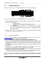
P ROGRAM 0 (N ORMAL )
By selecting the Program 0 (Normal) it is possible to command µTAB through the SERIAL 1 serial
communication port or the RADIO connector.
The commands that can be given to µTAB are listed in 3.1.1 µTAB Serial Frame – Self Timing.
Each command consists of an inizialitation character (ESC, ASCII 27), a character which identifies
the command, a line identifier (A,B,etc.) which makes it possible to address only the displayboards
you are interested in if there is more than one. The identifier 'A' corresponds to Address 0 on
µTAB, 'B' to Address 1 and so on. The character " " (ASCII 32 SPACE) refers to all the
displayboards without distinction (that is to say, the command is executed on all rows).
Commands end with a terminator (ETX,ASCII 03) and with a control character (checksum on 7 bits
of the characters that make up the command, STX and ETX included). This last character is
necesssary to decode the command. We strongly recommend the less experienced to exploit the
versatility of the program MICROGATE µBOARDS for Personal Computer to control µTAB
correctly, rather than making tedious attempts at direct programming.
NOTE: The commands identified with the term 'priority' or 'non-priority' (or 'strong' and 'weak')
should be understood to mean priority or non-priority with respect to the break command. For
example, a 'Weak Reset' command given after a break command will be executed only at the end
of the break. A 'Strong Reset', on the other hand, will be executed unconditionally.
RADIO INPUT
DECRADIO
BLUE
SOCKET
ENCRADIO
TO REI2, RACETIME2 O PC
RADIO: When the Linkgate system via radio is used in Program 0 (Normal), the type of radio
signal used is different from that of the other programs and it is advisable not to exceed a
transmitter/receiver distance greater than 150m.
CAB0xx
uTAB
BLACK
SOCKET
MODEM BUTTON
F igure 4
As can be seen in Figure 4, the DecRadio (or Decoder) is connected directly to the RADIO
connector on the displayboard, whereas the EncRadio (or Encoder) is connected to a PC, REI2 or
RACETIME2 with the appropriate cable (CAB073 for PC, CAB075 for RACETIME2 and CAB071
with CONNECTION BOX for REI2). To begin communication, the MODEM button on EncRadio
must be rhythmically pressed 3 times. Data transmission will take place at a velocity of 1200 bit/s.
µTAB Displayboard and Self-Timing Systems
17
User Manual
If 2 or more µGraphs commanded via Radio are being used, a special connector (ACC087) must
be connected to SERIAL 1 of the first displayboard. Without this connector pins 1 and 6 of the
Amphenol must be bridged.
•
1
2
3
4
5
6
SERIAL 1 Input/Output (6 pole Amphenol)
SERIAL 1 output RS232 TX
SYNC IN
SERIAL 1 input RS485 + RX
SERIAL 1 input RS485 - RX
Earth (cable braiding)
SERIAL 1 input RS232 RX
6 pole Amphenol connector
Setup
In Program 0 (Normal), setup allows you to re-initialize all µTAB parameters to standard values
and to set the first column displayed on the displayboard. The latter configuration makes it possible
to use two or more displayboards placed side by side. For example, if the displayboard is the
second element of the line, the first column will have to be set to 9.
Keep LAP-SETUP pressed for at least two seconds to enter Setup
Font
Set the Font type required with START-MODIFY
Press LAP-SETUP
X offset = 0
Offset the text displayed towards the right in relation to the left edge
with START-MODIFY (form 0 to 89)
Press LAP-SETUP
Baud = 1200
Set serial communication velocity with START-MODIFY (from 1200 bit/s
to 38400 bit/s (38k4); when setting RAD., instead of using the serial
connection to command µTAB, the Linkgate radio system is used)
Press LAP-SETUP
INT = RS232
Set the interface used for serial connection by using START-MODIFY
(the protocols available are RS232 and RS485)
Press LAP-SETUP
RadCh = 0
Set the Radio channel with START-MODIFY (from 0 to 127 except
channel 55)
Press LAP-SETUP
Green:
initialize
Sure?
Press START-MODIFY to confirm, LAP-SETUP to exit without initializing
Press START-MODIFY to confirm, LAP-SETUP to exit without initializing
µTAB Displayboard and Self-Timing Systems
User Manual
18
2.2
P ROGRAM 1 (M EMORY P ROGRAM )
Program 1 allows you to automatically run the previously set program. This program must be
stored while µTAB is in Program 0. To store the program, send the command 'Program Start',
then the sequence of commands that make up the program, finally the 'Program End' command.
Besides the normal commands, a program can contain loops with instructions automatically
repeated more than one time or an infinite number of times. The commands to be repeated must
be preceeded by the command 'Label', which makes it possible to define the position of the
program from which the commands to be repeated start. This command sequence must end with
the command 'Loop-Goto' which allows you to define the number of times the loop must be
repeated.
µTAB Displayboard and Self-Timing Systems
User Manual
19
2.3
P ROGRAM 2 (C HRONOMETER )
In this mode µTAB works as a typical chronometer set to 1/100 of a second.
• With Start (manually, from input or via radio) the chronometer starts.
• With Lap (manually, from input or via radio) the chronometer shows an intermediate time
for 5 seconds.
• With manual Start or Stop from input or via radio the chronometer stops.
• Now it is possible to set the chronometer to zero by pressing Lap.
If the chronometer is not set to zero, it will start from the value shown.
If the Autoreset time has been set to follow every Stop (or manual Start), the chronometer resets
itself to zero after the preset time.
NOTE: If the printer is connected, times are printed, coupled to a progressive counter which is
automatically set to zero every time Program 2 (Chronometer) is entered or µTAB is switched off.
RADIO: Program 2 (Chronometer) can also be used with a Linkgate system via radio. After the
radio channel has been correctly set (see par. 2.1 Program 0 (Normal) on p.16) the µTAB
displayboard will also accept START LAP and STOP signals coming from Linkgate.
Setup
It is possible to set the starting time of the chronometer.
Keep LAP-SETUP pressed for at least two seconds to enter Setup
Starttime
HH = 0
Set the hours with START-MODIFY
Press LAP-SETUP
MM = 0
Set the minutes with START-MODIFY
Press LAP-SETUP
SS = 0
Set the seconds with START-MODIFY
Press LAP-SETUP
mm = 0
Set the thousandths with START-MODIFY
Press LAP-SETUP
Autoreset
Time= 0
Set the automatic Reset time with START-MODIFY (in seconds). A time
of zero disables the Autoreset function.
Press LAP-SETUP
START-STOP
Press S TART-MODIFY to pass to START-START mode. In the latter case
every start event starts and stops the stopwatch.
Press LAP-SETUP
The stopwatch is now stopped on the set time, ready to start.
µTAB Displayboard and Self-Timing Systems
20
User Manual
2.4
P ROGRAM 3 (S PEEDMETER )
This mode allows you to measure the speed on the basis of any length. The speed is calculated on
the basis of the measurement of the time interval between two LAP-STOP input or via radio or
manual LAP-START impulses. So you need only place two photocells at the desired distance and
connect them to the Lap and Stop inputs. If the bidirectional mode has been set, the measurement
base can be run in both directions. Bidirectional mode is not recommended if it is not essential.
The system is able to manage up to 20 transits at the same time in the measurement base.
If a delay has been set for the activation of the stored program (see "Setup" below), when this time
is completed after the last measurement made, the display of the sequence stored as program is
automatically started. This auxiliary function allows automatic display of information or advertising
during the pauses between transits.
If the printer is connected, the speeds are printed, coupled to a progressive counter which is
automatically set to zero every time you enter mode 3 or µTAB is switched off.
NOTE: obviously, speed measurement precision depends on the accuracy with which time is
measured on the measurement base. To have a precision of 0.025 Km/h up to speeds of 130
Km/h, you need only place the photocells at least 10 m apart (using MICROGATE photocells).
Increasing the distance increases measurement precision.
POLIFEMO
ENCRADIO (Stop)
RADIO: As well as giving the manual LAP and START signals or input LAP or STOP, a Linkgate
system via radio can be used. In this case the following options are available:
A. Use of 2 Polifemo photocells and 2 Encoders or EncRadios. The signal of the first
EncRadio must be set on LAP (any), and that of the second on STOP.
ENCRADIO (any Lap)
POLIFEMO
DECRADIO
RADIO INPUT
BANANA CUBE
uTAB
BANANA CUBE
F igure 5
µTAB Displayboard and Self-Timing Systems
21
User Manual
In the example shown in Figure 5, 2 Polifemos connected to EncRadio through Banana Cube have
been used.
It is important to point out that if the EncRadios (or Encoders) have been set on LONG
transmission signals, the travelling time of the length base cannot be less than 3 seconds while the
time cannot be less than 1 second if SHORT signals are used.
B. Use of 2 Polifemo photocells and 1 Encoder or Encradio. The first photocell must be
connected (2 metre CAB050 cables or 20 metre CAB048 cables) to the Red and Black
banana jacks of the Encoder and the second to the Green and Black banana jacks. The
rotating selector for the selection of the signal on the Encoder must be set to LAP E.
With this option it is not possible to exploit the bidirectionality of the system or to have
more than one competitor in the measurement base.
BLACK PLUG IN
BLACK SOCKET
POLIFEMO
RADIO INPUT
DECRADIO
ENCRADIO
CAB048 or CAB050
BLACK PLUG IN
BLACK SOCKET
GREEN PLUG IN
GREEN SOCKET
GREEN PLUG IN
GREEN SOCKET
uTAB
POLIFEMO
GREEN PLUG IN
RED SOCKET
BLACK PLUG IN
BLACK SOCKET
BLACK PLUG IN
BLACK SOCKET
GREEN PLUG IN
GREEN SOCKET
F igure 6
Setup
It is possible to set the length of the measurement base, the speed unit, the minimum and
maximum speed allowed, the mono or bidirectional mode and the time lag with which the display
program is automatically activated.
Keep LAP-SETUP pressed for at least two seconds to enter Setup
Speedbase
Length ?
Press LAP-SETUP
km = 0
Set the kilometers with START-MODIFY
Press LAP-SETUP
m=0
Set the meters with START-MODIFY
Press LAP-SETUP
cm = 0
Set the centimeters with START-MODIFY
Press LAP-SETUP
Set Speed
Unit
Press LAP-SETUP
µTAB Displayboard and Self-Timing Systems
22
User Manual
kmh - mph - knt - m/s Edit using START-MODIFY (it is possible to
kilometers/hour, miles/hour, knots, meters/second).
Press LAP-SETUP
Min Speed
0 Kmh
Max Speed
0 Kmh
Bidir. = 0
Set Prog.
Delay
choose
from
Set minimum speed using Start-Modify (0=no checks are made;
another measurement unit can appear instead of "Kmh")
Press LAP-SETUP
Set maximum speed using Start-Modify (0=no checks are made;
another measurement unit can appear instead of "Kmh")
Press LAP-SETUP
Set bidirectional mode using START-MODIFY (0=No 1=Yes)
Press LAP-SETUP
Press LAP-SETUP
MM = 0
Set the minutes with START-MODIFY
Press LAP-SETUP
SS = 0
Set the seconds with START-MODIFY
Press LAP-SETUP
NOTE: Minimum and maximum speeds refer to the unit currently set.
µTAB Displayboard and Self-Timing Systems
User Manual
23
2.5
P ROGRAM 4 (C OUNTDOWN )
This mode allows you to display different kinds of countdown. Different display modes are obtained
by setting the Address selector to different values:
•
Address 0
In this mode µTAB simulates a timer for the start. The beeper is activated at -10 seconds, -5, -4, 3, -2, -1 and 0 seconds from the set start time. Normally, the built-in beeper is too weak. You are
therefore advised to connect the loudspeaker to the external socket on the side panel. The start
device (starting gate or other) should be connected to the START-STOP-LAP-INPUTS input. At
each start the deviation in minutes, seconds and thousandths relative to the scheduled starting
time (with the sign - for early start, + for delayed start) is displayed in sequence.
NOTE: the first start is given at the first net minute shown after Program 4 (Countdown) has been
activated.
Setup
The time intervals between successive starts, the green light time and the time displayed can be
pre-set (so as to synchronize the internal clock with other devices, usually the main chronometer).
The period between each start is set to 0 and the countdown from -10 seconds starts when the
LAP-SETUP key is pressed (or when the Lap input is activated).
In this way the start sequence can be set manually. In this case deviation from the scheduled start
time is neither displayed nor printed.
Keep LAP-SETUP pressed for at least two seconds to enter Setup
Cycletime
MM = 0
Set the minutes between each start with START-MODIFY
Press LAP-SETUP
SS = 0
Greentime
SS = 0
Sync.time
HH = 0
Set the seconds with START-MODIFY
Press LAP-SETUP
Set the seconds of green light time with START-MODIFY
Press LAP-SETUP
Set the hours with START-MODIFY
Press LAP-SETUP
MM = 0
Set the minutes with START-MODIFY
Press LAP-SETUP
SS = 0
Set the minutes with START-MODIFY
Press LAP-SETUP
mm = 0
Set the thousandths with START-MODIFY
Press LAP-SETUP
Now µTAB waits for a START (from key or input) for synchronization.
µTAB Displayboard and Self-Timing Systems
User Manual
24
NOTE: when setting the time for synchronization, µTAB shows the time at which the setting has
begun. If no value is modified, time is not changed and continues to run as if Setup had not been
used. This makes it possible to edit the other parameters without losing synchronization.
•
Address 1
The way this program functions is similar to that for address 0. In this case, however, at each start
the starting time (minutes, seconds and thousandths) and the deviation in minutes, seconds and
thousandths relative to the scheduled starting time (with the sign - for early start, + for delayed
start) are displayed in sequence.
•
Address 2
In this case the countdown starts from the time set by the user and stops at zero, with the last five
seconds signalled with a beep.
When started, the program automatically enters Setup
Cycletime
Press LAP-SETUP
MM = 0
Set the minutes between each start with START-MODIFY
Press LAP-SETUP
SS = 0
Set the seconds with START-MODIFY
Press LAP-SETUP
One cycle
Press “Start-Modify” to let the countdown restart automatically
Press Lap-SETUP
µTAB Displayboard and Self-Timing Systems
User Manual
25
2.6
P ROGRAM 5 (INTERNAL C LOCK )
This mode allows you to display the time on the µTAB internal clock.
Setup
It is possible to set the date and time of the internal clock.
NOTE: During time setting, µTAB shows the time at which the setting began. If no value is
modified, the time is not changed and runs as if Setup had not been used.
Keep LAP-SETUP pressed for at least two seconds to enter Setup
R.T. Date
day = 0
Set the day with START-MODIFY
Press LAP-SETUP
daynum = 0
Set the day of the week with START-MODIFY
(1 Sunday, 2 Monday,..., 7 Saturday)
Press LAP-SETUP
month = 0
Set the month with START-MODIFY
Press LAP-SETUP
year = 0
Set the year with START-MODIFY
Press LAP-SETUP
R.T. Clock
HH = 0
Set the hours with START-MODIFY
Press LAP-SETUP
MM = 0
Set the minutes with START-MODIFY
Press LAP-SETUP
SS = 0
Set the seconds START-MODIFY
Press LAP-SETUP
µTAB Displayboard and Self-Timing Systems
User Manual
26
2.7
P ROGRAM 6 (INTERNAL C LOCK AND D ATE )
This mode allows you to display the time and date on the µTAB internal clock.
Setup
It is possible to set the date and time of the internal clock.
µTAB Displayboard and Self-Timing Systems
User Manual
27
2.8
P ROGRAM 7 (L AP C HRONOMETER )
NOTE: This mode is not available on displayboards on which Progam 11 (Parallel Self-Timing) is
enabled.
Program 7 allows lap times timing. At each Start or Stop impulse (indifferently) the chronometer
takes the time from the previous impulse and restarts automatically from zero. Time continues to
be displayed for 8 seconds, then the running time appears again. The input and Lap key reset the
chronometer to zero.
NOTE: If the printer is connected, times coupled with a progressive counter which is automatically
set to zero every time Program 2 (Chronometer) is entered or μTAB is switched off, are printed.
RADIO: As well as giving the manual or input START, STOP and LAP signals, a Linkgate system
via radio can be used (after correctly setting the radio channel in the menu of Program 0 (Normal)).
The displayboard accepts any LAP signal.
Setup
It is possible to set the disactivation time of inputs after an impulse (holdoff time).
Keep LAP-SETUP pressed for at least two seconds to enter Setup
Starttime
HH = 0
Set the hours with START-MODIFY
Press LAP-SETUP
MM = 0
Set the minutes with START-MODIFY
Press LAP-SETUP
SS = 0
Set the seconds with START-MODIFY
Press LAP-SETUP
mm = 0
Set the thousandths with START-MODIFY
Press LAP-SETUP
Autoreset
Time= 0
Dead time
SS = 0
mm = 0
Set the automatic Reset time with START-MODIFY (in seconds). A time
of zero disables the Autoreset function.
Press LAP-SETUP
Set the seconds with START-MODIFY
Press LAP-SETUP
Set the thousandths with START-MODIFY
Press LAP-SETUP
µTAB Displayboard and Self-Timing Systems
User Manual
28
2.9
P ROGRAM 9 (T EST )
Program 9 (Test) is used to check the correct functioning of Pixels: the displayboard becomes
alternately yellow and black. If the displayboard is exposed to temperatures lower than -15°C
before being used, it is advisable to leave it switched on with this program inserted (for example,
outdoors at night in high mountains).
µTAB Displayboard and Self-Timing Systems
User Manual
29
2.10
P ROGRAM 10 (S ELF T IMING )
NOTE: This mode is available only on displayboards purchased with the Self-Timing option.
2.10.1
Starting Coin Box
The Starting coin box must be connected to the starting gate by connecting the special cable to the
"GATE" socket on the bottom of the coin box and to the starting gate (black and green sockets).
The coin box must also be connected to the finish through the"LINE" connector. For the connection
between start and finish use a four-pole cable (the only specification for the cable: the total
resistance of each cable should be less than 50 ohm - for example, for a 1000 m line, cables with a
section of 0.25 mm 2 or more are sufficient). The jacks supplied must be connected to the ends of
the cable, connecting poles 1, 2, 4, 6 of the jacks one at a time. Poles 3 and 5 are not used.
The third socket on the coin box is for powering a self-regulating warming resistance inside the
coin box itself. This prevents the blocking of the mechanical parts of the coin box when wet or
snow-covered coins are used and the external temperature is particularly low. Although it is not
normally neccessary to power the resistance, you are strongly recommended to do so. The
resistance must be powered at 24V (either direct or alternate). Consumption is high at the
beginning (200W max). Then it stabilises at about 20W (exact consumption depends on the
external temperature). The two resistance poles are connected to pins 1+2 (short-circuited) and
4+5 (short-circuited) of the "HEATING" jack.
NOTE: It must be stressed that if the warming resistance is not used, it is not necessary to power
the coin box.
2.10.2
Finish displayboard
Connect the line from the Start (see previous paragraph) to the SELF-TIMING socket of THE
displayboard with the jack supplied.
Connect the photocell to the S TART-STOP-LAP INPUTS socket of the displayboard with the cable
supplied. If you wish to take the exit speed, the intermediate time photocell must also be
connected. Consequently a suitable wire must be used with a connection box to connect the start
and intermediate time photocells.
With regard to power supply, remember that there are three different ways of powering the
MICROGATE Self-Timing (see also par. 1.3 Power supply on p.9):
A. By connecting the displayboard to the MICROGATE battery recharger/supply unit. In this way
the Self-Timing is powered from the mains supply and simultaneously the batteries are kept
charged by a trickle current. This guarantees perfect operation even if the mains supply is
interrupted.
B. By connecting the displayboard to any direct current source (whether stabilised or not) between
10 and 40 Volts, able to provide at least 4W peak power. A car battery guarantees a few days
of autonomous use.
C. By using the batteries built into the displayboard. In this case it is necessary to recharge the
batteries daily with the special battery recharger.
µTAB Displayboard and Self-Timing Systems
User Manual
30
2.10.3
Printer
It is possible to connect a printer with a built-in ticket cutting device to MICROGATE Self-Timing.
The printer must be connected to the SERIAL 2 port on the side panel of µTAB.
At the finish, for every competitor a card is printed for him/her to take. On the card the following
information appears:
• Two lines pre-set by the user (see below)
• Date, time and the competitor’s progressive number
• Competitor’s time
• Best race time
• Competitor’s exit speed (if the intermediate photocell has been installed)
• Best exit speed
The progressive number, the best time and the best speed are reset to zero by switching off μTAB
or by passing to a mode different from Program 10.
To set the first two lines which appear on the printer it is necessary to use a Personal Computer
and send the appropriate command to µTAB (on this subject, see par. 3.1.1 µTAB Serial Protocol –
Self Timing on p.40). The operation is easy and immediate if you use the MICROGATE
TABMICRO program.
2.10.4
Parallel automatic timing systems
Two or more Self-Timing systems can be installed in parallel. Each system works indipendently.
However, just one printer is enough for more than one system. It must be connected, as usual, to
the SERIAL 2 socket of one of the displayboards at the finish. The SERIAL 1 socket must be
connected to the SERIAL 2 socket of the other µTAB using the appropriate cable.
The tickets for both tracks are issued by the only printer.
We strongly recommend you identify the two tracks in different ways and indicate this identification
on the editable lines of the printer.
2.10.5
Operation
To activate Self-Timing just connect the system as previously described and switch on the
displayboard (Power switch), making sure that the "Program" switch is on 10 (Self-Timing).
The system starts functioning automatically when the first coin is inserted. The light on the coin box
can have three states:
• Red: track stopped (any possible start has no effect)
• Green: track free, the athlete can start
• Blinking Red/Green: track free, but less than 10 seconds are left to start.
The green light is coupled to a free track beeper. The beep becomes more frequent when less than
10 seconds are left to start (blinking Red/Green).
After every start the track can be stopped for a time which can be changed as desired (see next
paragraph), even if there are credits left. During this time the light remains red, and no start made
will be considered. The light remains red even if there are four competitors on the track
simultaneously.
If a competitor falls and does not finish the run, his/her time is automatically cancelled after a
maximum time that can be changed as desired (see next paragraph).
µTAB Displayboard and Self-Timing Systems
User Manual
31
It is also possible to set a minimum race time under which Stop signals are not accepted. This
minimum time has two functions. First it serves the purpose of eliminating "impossible" times
(obtained, for example, if all the gates are “missed”); secondly, it prevents the time of a competitor
who has abandoned the race from being assigned to another competitor who has overtaken
him/her.
NOTE: It is not necessary to wait until the track is free before inserting the coins. The system
automatically allows the number of transits that have been paid.
2.10.6
Parameters setting
When you enter the Self-Timing program, or when the displayboard is switched on, the question
"Setup?" appears for about 3 seconds. If during this period the Lap key (Setup) is kept pressed for
at least two seconds, you access the parameters which regulate Self-Timing. The settings
available are listed below.
Max. Time
Setting of the maximum race time, after which the racer is presumed
to have fallen (the chronometer resets itself to zero or passes to the
timing of the next competitor).
Press LAP-SETUP
MM = 0
Set the minutes with START-MODIFY
Press LAP-SETUP
SS = 0
Set the seconds with START-MODIFY
Press LAP-SETUP
Min. Time
Minimum race time under which the Stop impulses are not accepted
Press LAP-SETUP
MM = 0
Set the minutes with START-MODIFY
Press LAP-SETUP
SS = 0
Set the seconds with START-MODIFY
Press LAP-SETUP
Greentime
Setting of the time each racer has for the start (green light time),
including the 10 seconds of blinking light.
NOTE: the maximum time allowed is 9 minutes and 59 seconds. Two
values have a special meaning: - 10 minutes and 0 seconds: the light
remains green for an infinite time after each enablement until the
enablement is used with a start.
- 0 minutes and 0 seconds: the track is always free and coins do not
need to be inserted. This setting is useful when you want to use the
system to time a race, or when the payment of the races is not
necessary or is managed by other devices. The light turns red only
after each start for the minimum time between one start and the next.
MM = 0
Set the minutes with Start-Modify
Press LAP-SETUP
SS = 0
Set the seconds with START-MODIFY
Press LAP-SETUP
µTAB Displayboard and Self-Timing Systems
User Manual
32
Min
STARTDIFF
Setting of minimum time between two starts. During this time the light
is red and starts are not accepted even if there is a backlog of
enablements.
Press LAP-SETUP
MM = 0
Set the minutes with START-MODIFY
Press LAP-SETUP
SS = 0
Set the seconds with START-MODIFY
Press LAP-SETUP
Speedbase
Length ?
Setting of the distance between the intermediate time and finish
photocells for speed measurement.
Press LAP-SETUP
Km = 0
Set the kilometers with START-MODIFY
Press LAP-SETUP
m=0
Set the meters with START-MODIFY
Press LAP-SETUP
cm = 0
Set the centimeters START-MODIFY
Press LAP-SETUP
Set Speed
Unit
Press LAP-SETUP
kmh - mph - knt - m/s Edit using Start-Modify (it is possible to choose from kilometers/hour,
miles/hour, knots, meters/second).
Press LAP-SETUP
Set Prog.
Delay
Press LAP-SETUP
MM = 0
Set the minutes with START-MODIFY
Press LAP-SETUP
SS = 0
Set the seconds with START-MODIFY
Press LAP-SETUP
Linefeeds
N_lf = 0
Setting of the length of the paper that comes out of the printer
(optional) to set the correct length of the ticket - Edit using S TARTMODIFY.
NOTE: The setting of Self-Timing parameters by means of PC is not possible if µTAB is in
Program 10 (Self Timing). In this mode the only command accepted is 'Run Hardware Program'
(see 3.1 Appendix A on p.48). Go to Program 0 (Normal) before sending the parameters.
µTAB Displayboard and Self-Timing Systems
User Manual
33
2.10.7
Default value of editable parameters
When µTAB is delivered, or after every global initialization (see par. 2.1 Program 0 (Normal) on
p.18 in the general instructions), the configurable parameters are automatically set to the following
values (often suitable for many applications):
•
•
•
•
•
•
•
•
Maximum Race Time
Minimum Race Time
Green Light Time
Minimum Start between two starts
Speed Base Length
Speed unit
Delay Time of Program Activation
not been previously stored!!!).
Printer paper length
2.10.8
•
•
•
1' 30"
0' 0" (Stop is always enabled)
1'
0' 20"
10 meters
Km/h
0' 15" (obviously the program does not start if it has
0
Some suggestions
Avoid reducing the minimum time between two starts excessively as it can be dangerous to
have racers starting at very short time intervals.
Also avoid excessive reduction of the green light time, that is, the time that each racer has for
starting. Although the reduction of this parameter makes it possible to reduce the waiting time
at the start, too short a time can be unpleasant for customers, who find themselves obliged to
rush their starts.
If the photocell is used to take the exit speed, place it at least 8 - 10 meters before the finish
photocell to guarantee the necessary measurement precision (see also general instructions,
par.2.4 Program 3 (Speedmeter) on p.22).
µTAB Displayboard and Self-Timing Systems
User Manual
34
2.11
P ROGRAM 11 (P ARALLEL S ELF T IMING )
NOTE: This mode is available only on displayboards purchased with the Parallel Self-Timing
option
2.11.1
Connections
A. START FINISH CABLE
Connect the "Self-Timing" socket on the displayboard TAB to the LINE socket on the coin box,
using a six-polecable. Jacks must be connected 1 to 1 (1 to 1, 2 to 2, etc.). For cable
characteristics, see par. 2.10 Program 10 (Self Timing) on p.31.
B. STARTING GATES
The starting gates must be connected to the "GATE" socket on the coin box. The cable supplied is
double and makes possible the connection of both gates. One of the terminals is marked yellow.
We will refer to the track with the yellow cable as "Track B", the other as "Track A".
C. PHOTOCELLS
Photocells must be connected to the START-S TOP-LAP INPUTS socket of the displayboard. In
particular, the photocell for track A must be connected to the Stop line and the one for track B to
the Lap line.
Yellow-marked wires are for Lap.
NOTE: In "Parallel Self-Timing" it is not possible to take the exit speed.
2.11.2
Operation
To select the "Parallel Self-Timing" mode, set the PROGRAM rotating switch to 11.
The operation is exactly the same as the one described in par 2.10 Program 10 (Self Timing) on
p.31.
However, there are some distinctive features:
• PARALLEL RACE SELECTION:
Before inserting the coins, press the red button next to the the coin slot in the coin box .
After pressing, you have one minute to insert two coins and enable the start. The time between two
consecutive starts for the parallel (Track A and Track B) must not exceed 8 seconds. This
remaining time is indicated by blinking Red/Green and the beep.
On the displayboard the running time of the first racer to start is displayed with the track indication.
At the finish, first the time of the first racer to finish will appear, then the time of the other athlete
and finally the time difference with the indication of the winner.
• SINGLE RACE SELECTION:
The operation is exactly the same as Program 10 (Self Timing). To be enabled, you only need a
coin and the red button does not have to be pressed. The racer can choose to start either on
track A or on track B.
Also for parallel Self-Timing it is possible to have up to 8 racers maximum or couples of racers on
the track.
For setting of parameters see Program 10 (Self Timing) on p.31.
µTAB Displayboard and Self-Timing Systems
User Manual
35
NOTE: the settings are common to both modes (normal and parallel). Therefore, a change in
settings made in Program 10 (Self Timing) is also reflected in the functioning of Program 11
(Parallel Self Timing) and viceversa.
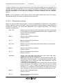
2.12
D EFAULT VALUES OF EDITABLE PARAMETERS
When µTAB is delivered or after each global initialization (see 2.10 Program 10 (Self Timing) p.18),
the configurable parameters are automatically set to the following values (often suitable for many
applications):
Program 0 (Normal) page 16
• Column
• Baud
• Frame
• RadCh
0
1200 bit/s
RS232
0
Program 2 (Chronometer) page 19
• Starting Time
0
• Autoreset Time
0
Program 3 (Speedmeter) page 20
• Speed base length
• Speed measurement unit
• Minimum speed
• Maximum speed
• Bidirectionality
• Program activation delay
10 meters
Km/h
3
0
0
0' 15"
Program 4 (Countdown) page 23
• Start Cycle
0' 30"
• Green light time
6"
(disabled)
(no control is made)
(No)
(Attention: the program does not start if it has
not been previously stored)
(from -3 to +3 in relation to the scheduled
time)
Program 7 (Lap Chronometer) page 27
• Holdoff
• time
0.2 sec.
NOTE: Also the time and date are preset to particular values.
µTAB Displayboard and Self-Timing Systems
User Manual
36
3
APPENDIX
µTAB Displayboard and Self-Timing Systems
User Manual
37
3.1
A PPENDIX A
3.1.1
µTAB Serial Frame – Self Timing
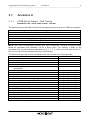
(1200 BAUD, 8 BIT, 1 STOP, PARITY NONE - 1200 8N1)
The table below gives the fields of which the commands that can be given to uTAB are composed.
Field
Start of Frame
Address
Command
Data
Frame end
Checksum
Length
1
1
1
Variable
1
1
Conten.
ESC (0x1B)
A...Q,‘ ’
(Any)
Variable
ETX (0x03)
Variable
Meaning
Start of Command frame
Line identifier, Blank for broadcast
Command to be sent to Displayboard (see below)
Optional command data area
End of Command frame
7 bit checksum performed on entire frame
NOTE: the µTAB communication protocol uses ASCII characters. Therefore numerical values
should be expressed with characters, not as a binary value. For example, a delay of 100
hundredths of a second should be expressed as ‘0’ ‘0’ ‘1’ ‘0’ ‘0’ (that is, Hex 30, Hex 30, Hex 31,
Hex 30, Hex 30), and not with the binary value 100 (Hex 64).
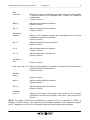
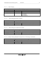
The table below gives the various commands which can be used in the Command field:
Command
Command Code
A
Dec. 65 - Hex 41h
• Date Display
B
Dec. 66 - Hex 42h
• Program start
C
Dec. 67 - Hex 43h
• Time setting sensitive to break
c
Dec. 99 - Hex 63h
• Time setting not sensitive to break
Dec. 68 - Hex 44h
• Break setting (breaks the execution of following D
commands)
d
Dec. 100 - Hex 64h
• Date setting
E
Dec. 69 - Hex 45h
• Entry Point/Label for loops
K
Dec. 75 - Hex 4Bh
• Program end
L
Dec. 76 - Hex 4Ch
• Loop/Goto
M
Dec. 77 - Hex 4Dh
• Internal clock time setting (Real Time Clock)
N
Dec. 78 - Hex 4Eh
• Internal clock time display (Real Time Clock)
O
Dec. 79 - Hex 4Fh
• Running string writing
o
Dec. 111 - Hex 6Fh
• Stop running string
P
Dec. 80 - Hex 50h
• Internal hardware program execution
p
Dec. 112 - Hex 70h
• Self-Timing printer strings
R
Dec. 82 - Hex 52h
• "Weak" displayboard reset (sensitive to Break)
r
Dec. 114 - Hex 72h
• "Strong" displayboard reset (not sensitive to Break)
S
Dec. 83 - Hex 53h
• Fixed string writing
s
Dec. 115 - Hex 73h
• Parameters setup
T
Dec. 84 - Hex 54h
• Display of set time
µTAB Displayboard and Self-Timing Systems
User Manual
38
3.1.1.1
Date dis play
Command Code
Item
Position (column)
Mode
3.1.1.2
Item
HHMMSSCC
Time setting sensitive to break
‘C’
Data
Length (bytes)
Notes
8
hours minutes seconds hundredths
Time setting not sens itive to break
Command Code
Item
HHMMSSCC
3.1.1.4
Length (bytes)
2
1
‘A’
Data
Notes
00 = first character on the left
0=disabling
1=GG/MM/AA
2=GG MMM AA
Time setting sens itive to break
Command Code
3.1.1.3
Date display
Time setting not sensitive to break
‘c’
Data
Length (bytes)
Notes
8
hours minutes seconds hundredths
Break setting (breaks the execution of following commands)
Break setting (breaks the execution of following commands)
Command Code
‘D’
Data
Item
Length (bytes)
Notes
Delay
5
Delay duration in hundredths
µTAB Displayboard and Self-Timing Systems
User Manual
39
3.1.1.5
Date setting
Date setting
Command Code
Item
Date
Day
3.1.1.6
Length (bytes)
6
1
Internal c lock time s etting (Real Time Clock)
Command Code
Item
HHMMSSCC
3.1.1.7
Internal clock time setting (Real Time Clock)
‘M’
Data
Length (bytes)
Notes
8
hours minutes seconds hundredths
Internal c lock time dis play (Real Time Clock)
Command Code
Item
Position (column)
Mode
3.1.1.8
‘d’
Data
Notes
DDMMYY format
1=Sunday 2=Monday ...
Internal clock time display (Real Time Clock)
‘N’
Data
Length (bytes)
Notes
2
00 = first character on the left
1
0 = disabling
1 = format HH:MM:SS
2 = format MM:SS
3 = format HH:MM 24h (ex. 15.25)
4 = format HH:MM 12h (ex. 3:25 PM)
Running string writing
Command Code
Item
Position (column)
N° of columns involved
Delay of string motion
String
Running string writing
Length (bytes)
2
2
3
<=255
‘O’
Data
Notes
00 = first character on the left
0 < n <= 81
In hundredths
Characters to be written
µTAB Displayboard and Self-Timing Systems
User Manual
40
3.1.1.9
Stop running string
Command Code
Item
HHMMSSCC
Stop running string
Length (bytes)
8
‘o’
Data
Notes
hours minutes seconds hundredths
3.1.1.10 Internal hardware program execution
Command Code
Item
N° of program
Internal hardware program execution
‘P’
Data
Length (bytes)
Notes
2
00 = 1st program (as for switch)
3.1.1.11 Self-Timing printer strings
Command Code
Item
Row 1
Row 2
Self-Timing printer strings
‘p’
Data
Length (bytes)
Notes
35
1st string
35
2nd string
3.1.1.12 "Weak" display board reset (sens itive to Break)
Command Code
Item
None
"Weak" displayboard reset (sensitive to Break)
‘R’
Data
Length (bytes)
Notes
3.1.1.13 "Strong" display board reset (not s ens itiv e to Break)
Command Code
Item
None
"Strong" displayboard reset (not sensitive to Break)
‘r’
Data
Length (bytes)
Notes
µTAB Displayboard and Self-Timing Systems
41
User Manual
3.1.1.14 Fixed string writing
Fixed string writing
Command Code
Item
Position (column)
String
Length (bytes)
2
<=81
‘S’
Data
Notes
00 = first character on the left
Characters to be written
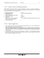
3.1.1.15 Parameters s etup
Parameters setup
Command Code
Item
Subcommand
Parameter
Length (bytes)
1
X
‘s’
Data
Notes
Alphabetic character (see below)
See below
Parameters Setup Subcommands
Countdown
A
999
B
999
Selftiming
C
999
D
999
I
999
E
999
F
9999999
L
999
M
999
U
999
SpeedMeter
G
999
H
9999999
u
999
S
999
s
999
d
999
Normal
N
999
ChronoLap
I
9999999
Countdown duration - 11<n≤500 (0=-10 sec., manual)
Valid Start Time - 0≤n≤500
Minimum time between two athletes - 10<n≤500
Maximum Track Time - 10<n≤500
Minimum Track Time - n≥0
Auto Program Time - 0≤n≤500
Speed Base Length in mt. - 0≤n≤50000.00
Green Light Time - 0≤n≤600 (0=xxx - 600=always green)
Number of Line-feeds of printer paper - 0≤n≤255
Unit (000=m/s 001=Kmh 002=mph 003=knt)
Auto Program Time - 0≤n≤500
Speed Base Length in mt. - 0≤n≤50000.00
Unit (000=m/s 001=Kmh 002=mph 003=knt)
Maximum Speed - n≥0
Minimum Speed - n≥0
Bidirectionality 0≤n≤1
First displayed column - 0≤n≤81
Holdoff Impulse - 5≤n≤50000
µTAB Displayboard and Self-Timing Systems
User Manual
42
3.1.1.16 Display of set time
Command Code
Item
Position (column)
Mode
Display of set time
Length (bytes)
2
1
‘T’
Data
Notes
00 = first character on the left
0 = disabling
1 = format HH:MM:SS
2 = format MM:SS
3 = format HH:MM 24h (ex. 15.25)
4 = format HH:MM 12h (ex. 3:25 PM)
µTAB Displayboard and Self-Timing Systems
43
User Manual
The following 4 commands are used for setting "programs" (series of operations to be performed in
sequence:
3.1.1.17 Program start
Command Code
Item
None
Program start
Length (bytes)
Data
Notes
‘B’
3.1.1.18 Program end
Command Code
Item
None
Program end
Length (bytes)
Data
Notes
‘K’
3.1.1.19 Entry Point/Label for loops
Command Code
Item
Label name
Entry Point/Label for loops
‘E’
Data
Length (bytes)
Notes
1
From 0 to 9
3.1.1.20 Loop/Goto
Command Code
Item
Label name
Loop number
Loop/Goto
Length (bytes)
1
2
‘L’
Data
Notes
From 0 to 9
00 = infinite loop
NOTE: numerical parameters with more than one digit must be padded (on the left) with zeros if
they occupy fewer characters than those fixed.
EXAMPLE: running string ("Microgate") on line A, starting from first column, number of columns
involved 9, delay 30 hundredths:
ESC - A - O - 00 - 09 - 030 - Microgate - ETX - Chk
µTAB Displayboard and Self-Timing Systems
44
User Manual
3.2
A PPENDIX B
3.2.1
Connection of starting coin box
1.
Line
1
2
3
4
5
6
Start
Enables
Parallel enables
Red line
Start 2
Green line
2
Heater
1
2
3
4
5
6
Pole 1
Pole 1
Not used
Pole 2
Pole 2
Not used
3.
Gate
1
2
3
4
1
6
Start (NO - Normally Open)
Not used
Ground
Not used
Start 2
Not used
LINE
HEATER
GATE
BOTTOM VIEW
µTAB Displayboard and Self-Timing Systems
User Manual
45
3.3
A PPENDIX C
3.3.1
Version with interface for different chronometers
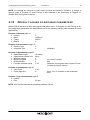
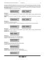
3.3.1.1
Program 12 – O mega O SM6 Chronometer
Program 12 makes it possible to connect the displayboard to the Omega OSM6 Chronometer.
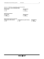
3.3.1.2
Program 13 – O mega Powertime Chronometer
Program 13 makes it possible to connect the displayboard to the Omega Powertime Chronometer.
By setting the Address selector to different values, different display modes are obtained.
ADDRESS 0
Display of the time with a precision of hundredths of a second and the competitor number. Set the
Powertime chronometer for the display of the hundredths of a second.
The data is displayed as follows:
MM:SS:DC
NNN
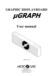
ADDRESS 1
Display of the time with a precision of tenths of a second and the competitor number. Set the
Powertime chronometer for the display of the tenths of a second.
The data is displayed as follows:
H:MM:SS:D
NNN
ADDRESS 2
Display of the time with a precision of seconds and the competitor number. Set the Powertime
chronometer for the display of the seconds.
The data is displayed as follows:
HH:MM:SS
NNN
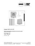
ADDRESS 3
Display of the speed and the competitor number. Set the Powertime chronometer for the display of
the speed.
The data is displayed as follows:
###.##
NNN
µTAB Displayboard and Self-Timing Systems
User Manual
46
NOTE: to return to the other function modes you must turn the rotating selector. The calculator
command does not function as in the “Powertime Emulation” program communication velocity is
different from the one usually used.
3.3.1.3
Program 14 – ALG E Chronometer
Program 14 makes it possible to connect the displayboard to the ALGE Chronometer.
By setting the Address selector to different values, different display modes are obtained.
ADDRESS 0
Displays minutes, seconds and thousandths (or tenths or hundredths according to the precision of
the work) in the following format:
MM:SS:DCM
ADDRESS 1
Displays hours, minutes and seconds in the following format:
HH:MM:SS
ADDRESS 2
Displays hours, minutes and seconds and tenths in the following format:
H:MM:SS.D
ADDRESS 3
Displays number and position in the following format:
NNN PP
ADDRESS 4
Is used with two µTAB displayboards (master and slave, or two masters, the second of which
should be configured for the display of characters from position 9 on).
The competitor number, the present position and the time in the format minutes, seconds, tenthshundredths-thousandths are displayed:
NNN PP
MM:SS:DCM
ADDRESS 5
Similar to the previous program, but with the time displayed in the format hours-minutes-secondstenths/hundredths.
NNN PP H
:MM:SS:DC
ADDRESS 6
The time is displayed in the format hours-minutes-seconds-tenths:
NNN PP H
H:MM:SS:D
µTAB Displayboard and Self-Timing Systems
User Manual
47
ADDRESS 7
The time is displayed in the format hours-minutes-seconds:
NNN PP
HH:MM:SS
ADDRESS 8
Displays minutes, seconds and thousandths (or tenths or hundredths according to the precision of
the work) in the following format:
HMMSS.DCM
ADDRESS 9
Displays hours, minutes and seconds in the following format:
HHMMSS
ADDRESS 10
Displays hours, minutes and seconds and tenths in the following format:
HMMSS.D
ADDRESS 11
Displays number, l minutes and seconds and tenths in the following format:
PPP M:SS.DC
ADDRESS 12
Displays number, l minutes and seconds and tenths in the following format:
PPP MM:SS.D
NOTE: to return to the other function modes you must turn the rotating selector. The calculator
command does not function as in the “Powertime Emulation” program communication velocity is
different from the one usually used.
3.3.1.4
Program 15 – O mega/Longines 5005/Ares Chronometers
Program 15 makes it possible to connect the displayboard to the Omega or Longines 5005 or Ares
Chronometers. By setting the Address selector to different values, different display modes are
obtained.
ADDRESS 0
Compatible with the programs ML 582 (Mass sport), ML590 (Road Cycling), ML584 (Show
jumping) etc.
µTAB Displayboard and Self-Timing Systems
User Manual
48
It makes it possible to display the running or final time (in the format minutes, seconds, and tenthshundredths-thousandths) and also the number and position. Two displayboards are used (master
and slave, or two masters, the second of which should be configured for the display of characters
from position 9 on).
The data is displayed in the following format:
MM:SS:DCM
NNN RRR
ADDRESS 1
Compatible with the programs ML 582 (Mass sport), ML590 (Road Cycling), ML584 (Show
jumping) etc.
Similar to the previous program. The time is displayed in the format hours-minutes, secondstenths:
H:MM:SS:D
NNN RRR
ADDRESS 2
Compatible with the ML programs.
Similar to the previous program. The time is displayed in the format hours-minutes, seconds:
HH:MM:SS
NNN RRR
ADDRESS 3
Compatible with the programs ML 582 (Mass sport), ML590 (Road Cycling), ML584 (Show
jumping) etc.
Displays only number and position:
NNN RRR
ADDRESS 4
Compatible with the program ML 582 (Mass sport).
Displays number and position, in four-figure format:
NNNN RRRR
ADDRESS 5
Compatible with the program ML 683 (Car-Motorbike).
Displays LAP time in the following format:
MM:SS:DCM
ADDRESS 6
Compatible with the program ML 683 (Car-Motorbike).
Displays speed in kilometres per hour, in the following format:
###:## Kmh
µTAB Displayboard and Self-Timing Systems
User Manual
49
ADDRESS 7
Compatible with the program ML 683 (Car-Motorbike).
Displays speed in miles per hour, in the following format:
###:## mph
ADDRESS 8
Compatible with the programs ML 582 (Mass sport), ML590 (Road Cycling), ML552/553 (Alpine
skiing and Nordic skiing), ML597 (Horse racing), ML 566 (Track skating).
Displays the time of day in the following format:
HH:MM:SS
ADDRESS 13
Compatible with the programs ML 566 (Track skating).
Displays the number and ‘status’ (in/out) of competitors A and B in the following format:
NNN
IN
NNN OUT
ADDRESS 14
Compatible with the programs ML 566 (Track skating).
Displays the number and laps to go for competitors A and B in the following format:
NNN - GGG
NNN - GGG
NOTE: to return to the other function modes you must turn the rotating selector. The calculator
command does not function as in the “Powertime Emulation” program communication velocity is
different from the one usually used.
µTAB Displayboard and Self-Timing Systems
50
User Manual
3.3.1.5
Note for connection of c hronometers
OMEGA/LONGINES 5005 CHRONOMETERS
Chronometer
4 – TX+
3 – TX-
Displayboard
5 – GND
6 – Serial IN
ALGE CHRONOMETERS
Chronometer
3 – GND
5 – Serial OUT
Displayboard
5 – GND
6 – Serial IN
OMEGA POWERTIME CHRONOMETERS
CHRONOMETER (RJ4 socket)
CHRONOMETER (9 pole Cannon)
1 – TX+
1 – TX+
3 – TX9 – TX-
Displayboard
5 – GND
6 – Serial IN
Microgate S.r.l.
Via Stradivari, 4
I-39100 BOLZANO - ITALY
http://www. micro gate.it