1
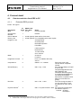
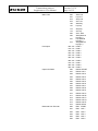
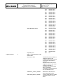
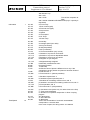
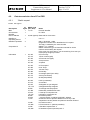
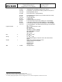
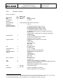
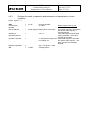
REI 2
Transmission protocol
Supplement to User Manual
Doc: R2U_3_1079_001_E
Version: 1.07.9
Page 1 of 32
+D/2
Transmission protocol
REI 2
Transmission protocol
Supplement to User Manual
Doc: R2U_3_1079_001_E
Version: 1.07.9
Page 2 of 32
Summary
1.
PRINCIPLE OF FUNCTIONING .............................................................................. 3
1.1.
Off-line data transmission.....................................................................................................3
1.2.
On-line data transmission .....................................................................................................3
1.3.
Interactive PC-REI2-PC communication............................................................................3
1.3.1.
‘Static’ request .................................................................................................................4
1.3.2.
‘Dynamic’ request ...........................................................................................................4
1.3.3.
Status request ...................................................................................................................5
1.3.4.
Request for break, transmission suspension/resumption, record repetition ....................5
1.3.5.
Error in the request ..........................................................................................................5
1.4.
Insertion of time events .........................................................................................................5
2.
GENERAL INFORMATION ABOUT THE REI2- PC PROTOCOL.......................... 6
3.
OBSERVATIONS REGARDING CONNECTION TO TV......................................... 6
4.
PROTOCOL DETAIL............................................................................................... 7
4.1.
Data transmission from REI2 to PC ....................................................................................7
4.1.1.
Extended REI2 protocol ..................................................................................................7
4.1.2.
Reduced REI2 protocol..................................................................................................12
4.1.3.
‘Static’ reply ..................................................................................................................13
4.1.4.
Error reply......................................................................................................................18
4.1.5.
REI2 status reply............................................................................................................19
4.1.6.
REI2 status reply codes .................................................................................................20
4.2.
Data transmission from PC to REI2 ..................................................................................23
4.2.1.
‘Static’ request ...............................................................................................................23
4.2.2.
‘Dynamic’ request .........................................................................................................25
4.2.3.
Request for break, suspension and resumption of transmission, record repetition .......27
4.2.4.
Status request .................................................................................................................28
4.3.
Event transmission from PC to REI2 ................................................................................29
4.3.1.
Time insertion................................................................................................................29
4.4.
Printout transmission from PC to REI2...........................................................................30
5.
MODIFICATION HISTORY.................................................................................... 31
REI 2
Transmission protocol
Supplement to User Manual
Doc: R2U_3_1079_001_E
Version: 1.07.9
Page 3 of 32
1. Principle of functioning
There are three basic functioning modes:
1) Off-line data transmission
2) On-line data transmission
3) Interactive PC-REI2 communication
1.1.
Off-line data transmission
Off-line data transmission consists of the transference of data during a timing session after an
interval of time. Naturally the timekeeper must enter the relative ‘menu’ on REI 2 to request data
transmission.
The transfer of various types of data can be chosen:
Net times
Event times
Non-starters
Non-finishers
Disqualified
Speed
Each item can be filtered on the basis of a run, group or particular time interval (i.e. downloads all
the event times of run 2 of those in group 3 between 12:00:00.0000 and 13:00:00.0000).
The protocol used for data transmission from REI2 to PC is Extended REI2 protocol (see
description below) with the mode flag equal to ‘F’.
1.2.
On-line data transmission
On-line data transmission consists of the transmission from REI2 to PC of the whole operation of
acquisition, correction and annulment of times performed by the timekeeper on the machine (in
practice, all the information given on the printout is transmitted). Once enabled, transmission takes
place completely autonomously each time a time is acquired or modified. Each record transmitted
is identified by a counter (from 0 to 99999 with wrap-around), which goes up automatically.
Also in this case, the protocol used for transmission is Extended REI2 protocol (see description
below) with the mode flag equal to ‘O’.
It is also possible to activate an output on the serial line corresponding to the output of the main
displayboard, with intervals which can be set; in this case the transmission protocol used for
transmission is Reduced REI2 protocol (see description below).
1.3.
Interactive PC-REI2-PC communication
The requests the PC can forward to REI2 can be subdivided into four types:
1) ‘Static’ requests
2) ‘Dynamic’ requests
REI 2
Transmission protocol
Supplement to User Manual
Doc: R2U_3_1079_001_E
Version: 1.07.9
Page 4 of 32
3) Status requests
4) Break requests
Each request made by the PC to REI2 is identified not only by the type of request but also by a 5figure identification number. The number concerned is used by the reply in such a way that the
pairing is unique.
1.3.1.
‘Static’ request
A static request is made each time the PC needs to access one or more elements of the
chronometer’s database. The ‘Static’ request, protocol allows you to filter the elements of the
database according to the requirements of the moment. The possibility of obtaining running times
in reply is not provided for in this type of request.
The ‘Static’ request protocol also offers the possibilty of making requests to which the
chronometer must reply with a number of records. (for example, a request for all the NPs of run 1).
In this case the identification number given in the replies remains the same for all the replies
corresponding to the same request.
The reply to a static request is in conformity with the Extended REI2 protocol. The reply to a
‘Static’ request differs from autonomous on-line and off-line transmission in the initial protocol
identification character.
1.3.2.
‘Dynamic’ request
A ‘dynamic’ request allows you to activate running times on the specified serial line with the
possibility of defining the time interval between one transmission and the next (from 1/100s a
999,99s, in steps of 1/100s) .
To guarantee maximum flexibility of use, the chronometer puts in line a Tout running time
specified as follows:
Tout=Tnow-Tev-Taux
where
Tnow = present time of the machine (real time, as at initial synchronisation)
Tev =
event time. The event time should be specified as type of event, competitor number and
run. It is also possible not to specify this parameter (simply by assigning 0 to the athlete’s
number). In this case, REI2 assumes Tev=0.
Taux = generic time, communicated to REI2 by the PC. It is also possible to specify a negative
sign for Taux
Taux = therefore allows you to ‘shift’ the running time of a competitor as desired by a fraction of
a second. This is particularly useful during showing on TV.
REI2 can manage a maximum of 2 running times simultaneously.
The output of running times occurs in accordance with the ‘Dynamic’ reply protocol.
REI 2
Transmission protocol
Supplement to User Manual
1.3.3.
Doc: R2U_3_1079_001_E
Version: 1.07.9
Page 5 of 32
Status request
A status request allows you to obtain information regarding the settings parameters of the machine
(status of lines, line disactivation times, program set, etc.).
The request contains a code relative to the parameter you wish to check. The reply takes place in
accordance with the Status reply protocol and although maintaining the same structure and
dimension, can present differences depending on the parameter requested.
1.3.4.
Request for break, transmission suspension/resumption, record repetition
A break request allows you to annul the reply to a particular static request. The reply to be
interrupted is identified by its identification number. A reply to the break request is not required.
This command can be particularly useful for interrupting transmission after a static request for
which there is more than one reply record.
The request for suspension and resumption of the communication makes it possible to implement a
SW Xon/Xoff protocol. During suspension, the items of information are put in a queue. If the
queue is full, the following records are lost. This possibility can easily be identified subsequently
through requests which receive no reply or discontinuity in the incremental identification number
for on-line information.
Any replies to requests which are lost can be recovered by repeating the request.
Lost on-line transmission records can be recovered by sending a request for repetition of the record.
1.3.5.
Error in the request
If a request contains a syntactic error or cannot be interpreted correctly by REI2, a general error
code of the consecutive number of the request in which the error was found is sent back.
1.4.
Insertion of time events
The request for insertion of time events, available from software version 1.07 on, allows insertion
and annulment of time events and insertion of NP and NA indications in the REI2 database using a
serial connection. The protocol specifications are given in chap. 4.3 Event transmission from PC to
REI2 on p.29. The physical channel assigned to insertion from PC is 900.
REI2 does not do any kind of check on the congruity of data sent for insertion. All
checking must be made with procedures external to the chronometer.
REI 2
Transmission protocol
Supplement to User Manual
Doc: R2U_3_1079_001_E
Version: 1.07.9
Page 6 of 32
2. General information about the REI2- PC protocol
Some general information about the implementation of the REI2-PC protocol:
The transmission of commands and the reception of replies contain only ASCII codes.
Each request or reply has an initial header for each particular protocol with an ASCII control
code (code character < 0x20 (space).
Each request or reply ends with a ‘carriage return’ (CR, 0x0d).
After the initial character which identifies the protocol, each request and reply (with the
exception of ‘dynamic’ reply) has two characters to identify the type of device (REI2) and the
device’s address. This function makes it possible to connect a number of devices on the same
communication line.
Each request can send the reply on the same serial channel on which it was received, on one of the two channels you
can choose to make available (independently of which channel is used for requests) or on both serial outputs. It is
possible to pilot the displayboard output by using the dynamic request identifier “T” requested. (see chap. 4.2.2
‘Dynamic’ request on p.25).
3. Observations regarding connection to TV
When running times are displayed (e.g. connection to TV) it is advisable to use the tick or dynamic
responses and not on-line data as the latter might have a delay of a few tenths of a second.
In the following programs different types of information can be emitted for the tick simultaneously:
PARALLEL SLALOM or DUAL TIMER: if the two competitors have already started the
race, it is the running time for each track. When a competitor finishes, instead of running
time tick output is the gap, positive or negative, between him/her and the competitor still
racing.
SHOW JUMPING: as well as running time, REI2 also sends the athlete’s penalty.
SIMPLE STOPWATCH: after the first competitor has finished, if “Displayboard block after
first finish: Active” is set, the output is the net time of the first competitor plus the gap.
When LinkPod or EncRadio devices are used with tick output, it is advisable to enter a delay
time (for LinkPod 120ms is recommended, for EncRadio 200ms) which can be set in “Serial
ports setup” by pressing <ALT>+<F2>.
REI 2
Transmission protocol
Supplement to User Manual
Doc: R2U_3_1079_001_E
Version: 1.07.9
Page 7 of 32
4. Protocol detail
4.1.
Data transmission from REI2 to PC
4.1.1.
Extended REI2 protocol
Total 52 bytes
Description
DLE
N° ASCII Code
bytes (Dec, Hex)
1
16,10h
Chronometer
identifier
Device address
Dummy char
Program in use
1
1
1
Mode
1
Progressive counter
6
Competitor N°
5
Group/Category
3
Run/Trial
3
Physical channel 1
3
1
1
Notes
Protocol identifier
R=REI2
32,20h (space) Reserved for future uses
32,20h (space) For compatibility with ‘static’ replies
S=Single Starts
G=Group starts
B=Simple stopwatch
P=Parallel
I=Show jumping
N=Swimming
T=Track Chase
O=Pc OnLine
O=OnLine
F=OffLine
From 1 to 999999, with wrap
around
00000<= N <=59999
Zero in the case of PC
OnLine without competitor
number
000<= Ng <=199
If the Group/Category is equal
to zero or the
Groups/Categories have not
been defined or the
information filtered by group
is not being downloaded (it is
not always downloaded
because the competitor could
belong to more than one
group)
001<= Nm <=250
For horse racing the phase 1
run can range from 1 to 99,
the phase 2 run from 100 to
198
000<= Physical channel <=999 If the physical channel does
not exist the output is “ “
Channel Channel
Description
Note: for the simple stopwatch and the parallel, the output has a different meaning:
• PARALLEL: The output data item is the progressive number of direct contests
REI 2
Transmission protocol
Supplement to User Manual
Main Lines
Doc: R2U_3_1079_001_E
Version: 1.07.9
Page 8 of 32
000
001
015
016
100
101
115
116
200
300
301
315
Pod Inputs
Inputs Via Radio
Retrieved from Encoder
400..407
410..417
420..427
430..437
440..447
450..457
460..467
470..477
480..487
490..497
500
501
502
503
504
505
506
507
508
509
510
511
512
513
514
515
600
601
602
603
604
605
Start Line
Lap Line
Stop Line
Aux Line
Start Key
Lap key
Stop key
Aux key
Auto Start
Start (Manual
keying in)
Lap (Manual
keying in)
Stop (Manual
keying in)
POD 0
POD 1
POD 2
POD 3
POD 4
POD 5
POD 6
POD 7
POD 8
POD 9
RADIO START
RADIO LAP 1
RADIO LAP 2
RADIO LAP 3
RADIO LAP 4
RADIO LAP 5
RADIO LAP 6
RADIO LAP 7
RADIO LAP 8
RADIO LAP 9
RADIO LAP A
RADIO LAP B
RADIO LAP C
RADIO LAP D
RADIO LAP E
RADIO STOP
ENC START
ENC LAP 1
ENC LAP 2
ENC LAP 3
ENC LAP 4
ENC LAP 5
REI 2
Transmission protocol
Supplement to User Manual
Doc: R2U_3_1079_001_E
Version: 1.07.9
Page 9 of 32
Imputed by RadioModem
Serial A RADIO Inputs
Serial B RADIO Inputs
Logical Channel
3
Imputed by PC
000<= Logical channel <=255
606
607
608
609
610
611
612
613
614
615
700
ENC
ENC
ENC
ENC
ENC
ENC
ENC
ENC
ENC
ENC
LAP 6
LAP 7
LAP 8
LAP 9
LAP A
LAP B
LAP C
LAP D
LAP E
STOP
516
517
518
519
520
521
522
523
524
525
526
527
528
529
530
531
532
533
534
535
536
537
538
539
540
541
542
543
544
545
546
547
RADIO START
RADIO LAP 1
RADIO LAP 2
RADIO LAP 3
RADIO LAP 4
RADIO LAP 5
RADIO LAP 6
RADIO LAP 7
RADIO LAP 8
RADIO LAP 9
RADIO LAP A
RADIO LAP B
RADIO LAP C
RADIO LAP D
RADIO LAP E
RADIO STOP
RADIO START
RADIO LAP 1
RADIO LAP 2
RADIO LAP 3
RADIO LAP 4
RADIO LAP 5
RADIO LAP 6
RADIO LAP 7
RADIO LAP 8
RADIO LAP 9
RADIO LAP A
RADIO LAP B
RADIO LAP C
RADIO LAP D
RADIO LAP E
RADIO STOP
900
PC
REI 2
Transmission protocol
Supplement to User Manual
000=START
001..240= LAP n
248=REAL_START_CBASE
249=TIME_RESET_CBASE
Information
1
Doc: R2U_3_1079_001_E
Version: 1.07.9
Page 10 of 32
For simple stopwatch: SPLITs
with LAP have a range from
001 to 200,
SPLITs without LAP have a
range from 201 to 240.
If the maximum number is
exceeded the previous item of
data is cancelled. The
finishes following the first are
considered as LAP.
Real time of start event in
simple stopwatch mode
Time of reset event on simple
stopwatch when it counts
down
72,48h
104,68h
73,49h
105,69h
74,4Ah
106,6Ah
112, 70h
107,6Bh
250=Generic Lap
254=AUX
255=STOP
245=SHOW JUMPING INFORMATION (only if a penalty is
requested)
0=Time of day
1=Run net time (split)
2=Total net time (split)
3=Lap net time
4=Speed
5=Time speed
6=Air Temp.
7=Snow Temp.
8=Humidity
9=Average speed (non radio)
T=Average start-stop speed
A= A (non-finisher)
Q=SQ (disqualified)
P=NP (not started)
a=Annulled
S=Skipped not yet assigned
s=Skipped already assigned
K=Manually modified time event
G=Effective time of phase is different from 0 only if the
competition has two phases and phase 2 has been finished
H=Total time tab. A
h=Total time tab. C (without penalties)
I=Penalties imposed tab. A
i=Penalties imposed (seconds) tab. C
J=Penalties for exceeding maximum time, tab. A
j=Penalties in seconds for exceeding maximum time, tab. C
p=Total penalties, tab. A
k=Final time tab C. (with penalties)
103,67h
g= Gundersen time (active only if it refers times to the first)
48, 30h
49, 31h
50, 32h
51, 33h
52, 34h
53, 35h
54, 36h
55, 37h
56, 38h
57, 39h
84,54h
65, 41h
81, 51h
80, 50h
97, 61h
83, 53h
115, 73h
75, 4Bh
71,47h
REI 2
Transmission protocol
Supplement to User Manual
99, 63h
85, 55h
87, 57h
119, 77h
88 ,58h
90 ,5Ah
Doc: R2U_3_1079_001_E
Version: 1.07.9
Page 11 of 32
c= Time event substituted
U= Duration of competition suspension in Show Jumping
program
W= Wind speed
w= Wind direction
X= Brightness
Z= Net lap time (only for Basic Stopwatch)
Time in ten thousandths of a second 12345678980
corresponds to 12:34:56.7890
In the case of speed, the string means 123.456kmh
When the info field is equivalent to I,J,K,i,j the penalty (points or
seconds) is transmitted in hundredths in the form #####.####
Date in the following format 231201 corresponds to 23/12/2001
In the case of net time it is the number of days in the following
format ±1234567
If a penalty comes up indicates if this is positive or negative
Time/Speed
10
Date
8
Dummy char
CR
2
1
13,0Dh
Free bytes for future applications
Carriage Return
LF
1
10,0Ah
Line feed
REI 2
Transmission protocol
Supplement to User Manual
4.1.2.
Doc: R2U_3_1079_001_E
Version: 1.07.9
Page 12 of 32
Reduced REI2 protocol
Total 33 bytes
Description
DC4
Device address
Identifier of
requesting device
N°
bytes
1
1
1
Competitor N°
Information
5
1
Time
10
Number of days
1
ASCII Code
Notes
(Dec, Hex)
20, 14h
Protocol identifier
32,20h (spac) Reserved for future uses
0..9 A..z
65, 41h
66, 42h
67, 43h
68, 44h
80, 50h
69, 45h
84, 54h
83, 53h
97, 61h
98, 62h
99, 63h
100,64h
112, 70h
101,65h
116, 74h
115, 73h
43, 2Bh
(48,30h) ..
(57,39h)
45, 2Dh
82, 52h
66, 42h
Run/Trial
Lap
3
3
Position
3
48, 30h (3
times)
45, 2Dh (3
times)
43, 2Bh
(3times)
Dummy char
CR
LF
2
2
1
1
13,0Dh
10,0Ah
If the output is enabled by REI2 the code is 20h ' '
00000<= N <=59999
A=Run running time (split)
B=Total running time (split)
C=Lap running time
D=Dynamic output running time
P=Running penalties 2
E= Gundersen running time
T= Running gap positive
S= Running gap negative
a=Run net time (split)
b=Total net time (split)
c=Lap net time
d=Dynamic output net time
p=Penalties total
e= Gundersen net time
t= Net gap positive
s= Net gap negative
Net time in ten thousandths of a second is padded with zeros
depending on the precision set
0034567800 corresponds to 00:34:56.7800
"-" = negative number of days 3
0..9 Number of days
"+" = number of days of net time is greater than 9 3
R= in PARALLEL or DUAL TIMER program for RED track
B= in PARALLEL or DUAL TIMER program for BLUE track
001<= Nm <=250 2
000<= Nlap <=240
If the information does not refer to an intermediate, 000 is sent
Position of first 999 competitors
000= Calculation of ranking disabled
"---" = the ranking is being recalculated
"+++" = the position of the competitor is greater than 999
Free bytes for future applications
Carriage Return
Line feed
For show jumping, the run of phase 1 can range from 1 to 99, the run of the second phase from 100 to 198
The penalty comes up at the same time as running time
3
If a penalty comes up indicates if this is positive or negative
2
REI 2
Transmission protocol
Supplement to User Manual
4.1.3.
Doc: R2U_3_1079_001_E
Version: 1.07.9
Page 13 of 32
‘Static’ reply
Total 52 bytes
Description
DC2
N° ASCII Code
bytes (Dec, Hex)
1
18,12h
Notes
Protocol identifier
Chronometer
identifier
Device address
Program in use
1
R=REI2
1
1
Mode
1
32,20h (space) Reserved for future uses
S=Single Starts
G=Group starts
B=Simple stopwatch
P=Parallel
I=Show jumping
N=Swimming
T=Track Chase
O=Pc OnLine
O=OnLine
F=OffLine
Status reply
1
Identifier of
requesting device
Identifier reply
1
R: the record transmitted refers to the n _th request
E: the record transmitted is the last for the n _th request
Z: response not available for the n _th request
0..9 A..z
5
00000<= Nresponse <=99999
Competitor N°
Group/Category
5
3
00000<= N <=59999
000<= Ng <=199
Run/Trial
Physical channel 3
3
3
001<= Nm <=250
000<= Physical channel <=255
Main Lines
3
Progressive number which
identifies the PC request, or
progressive number for
information sent
autonomously in on-line and
off-line modes.
If the Group/Category is equal
to zero or the
Groups/Categories have not
been defined or the
information filtered by group
is not being downloaded (it is
not always downloaded
because the competitor could
belong to more than one
group)
Channel
000
Channel
Description
Start Line
Note: for the simple stopwatch and the parallel, the output has a different meaning:
• SIMPLE STOPWATCH: The output data item is the number of events of the race set which have been
memorised. If the event is a stop, it is the lap number
• PARALLEL: The output data item is the progressive number of direct contests
REI 2
Transmission protocol
Supplement to User Manual
Pod Inputs
Via Radio Inputs
Retrieved by Encoder
Imputed by RadioModem
Serial A RADIO Inputs
Doc: R2U_3_1079_001_E
Version: 1.07.9
Page 14 of 32
001
015
016
100
101
115
116
200
300
301
315
400..407
410..417
420..427
430..437
440..447
450..457
460..467
470..477
480..487
490..497
500
501
502
503
504
505
506
507
508
509
510
511
512
513
514
515
600
601
602
603
604
605
606
607
608
609
610
611
612
613
614
615
700
516
517
518
Lap Line
Stop Line
Aux Line
Start Key
Lap Key
Stop Key
Aux Key
Auto Start
Keyb Start
Keyb Lap
Keyb Stop
POD 0
POD 1
POD 2
POD 3
POD 4
POD 5
POD 6
POD 7
POD 8
POD 9
RADIO START
RADIO LAP 1
RADIO LAP 2
RADIO LAP 3
RADIO LAP 4
RADIO LAP 5
RADIO LAP 6
RADIO LAP 7
RADIO LAP 8
RADIO LAP 9
RADIO LAP A
RADIO LAP B
RADIO LAP C
RADIO LAP D
RADIO LAP E
RADIO STOP
ENC START
ENC LAP 1
ENC LAP 2
ENC LAP 3
ENC LAP 4
ENC LAP 5
ENC LAP 6
ENC LAP 7
ENC LAP 8
ENC LAP 9
ENC LAP A
ENC LAP B
ENC LAP C
ENC LAP D
ENC LAP E
ENC STOP
RADIO START
RADIO LAP 1
RADIO LAP 2
REI 2
Transmission protocol
Supplement to User Manual
Doc: R2U_3_1079_001_E
Version: 1.07.9
Page 15 of 32
Serial B RADIO Inputs
Logical Channel
3
Imputed by PC
000<= Logical channel <=255
000=START
001..240= LAP n
248=REAL_START_CBASE
249=TIME_RESET_CBASE
519
520
521
522
523
524
525
526
527
528
529
530
531
532
533
534
535
536
537
538
539
540
541
542
543
544
545
546
547
900
RADIO LAP 3
RADIO LAP 4
RADIO LAP 5
RADIO LAP 6
RADIO LAP 7
RADIO LAP 8
RADIO LAP 9
RADIO LAP A
RADIO LAP B
RADIO LAP C
RADIO LAP D
RADIO LAP E
RADIO STOP
RADIO START
RADIO LAP 1
RADIO LAP 2
RADIO LAP 3
RADIO LAP 4
RADIO LAP 5
RADIO LAP 6
RADIO LAP 7
RADIO LAP 8
RADIO LAP 9
RADIO LAP A
RADIO LAP B
RADIO LAP C
RADIO LAP D
RADIO LAP E
RADIO STOP
PC
The SPLITs with LAP have a
range from 001 to 200
(corresponding to the number
of times the stop button is
pressed)
SPLITs without LAP have a
range from 201 to 240. If the
maximum number is
exceeded, the previous data
item is cancelled
The finishes following the first
are considered as LAP.
Real time of start event in
simple stopwatch mode
Time of reset event on simple
stopwatch when it counts
down
REI 2
Transmission protocol
Supplement to User Manual
Doc: R2U_3_1079_001_E
Version: 1.07.9
Page 16 of 32
250=Generic Lap
254= AUX
255= STOP
Information
1
48, 30h
49, 31h
50, 32h
51, 33h
52, 34h
53, 35h
54, 36h
55, 37h
56, 38h
57, 39h
65, 41h
81, 51h
80, 50h
97, 61h
110, 6Eh
113, 71h
112, 70h
83, 53h
115, 73h
75, 4Bh
82,52h
84,54h
71,47h
72,48h
104,68h
73,49h
105,69h
74,4Ah
106,6Ah
112, 70h
107,6Bh
103,67h
99, 63h
85, 55h
87, 57h
119, 77h
88 ,58h
Time/Speed
10
Time of first competitor at
finish
245= SHOW JUMPING INFORMATION (only if a penalty is
requested)
0=Time of day
1=Run net time (split)
2=Total net time (split)
3=Lap net time
4=Speed
5=Time speed
6=Air Temp.
7=Snow Temp.
8=Humidity
9=Average speed (non radio)
A=NA (non-finisher)
Q=SQ (disqualified)
P=NP (not started)
a=Time event deletion (only on-line)
n=Deletion of a previous non-finisher
q=Deletion of a previous disqualified athlete
p=Deletion of a previous non-starter
S=Skipped not yet assigned
s=Skipped already assigned
K=Manually modified time event
R=Present position
T=Start-stop
G=Effective time of phase is different from 0 only if the
competition has two phases and phase 2 has been finished
H=otal time tab. A
h=Total time tab. C (without penalties)
I=Penalties imposed tab. A
i=Penalties imposed (seconds) tab. C
J=Penalties for exceeding maximum time, tab. A
j=Penalties in seconds for exceeding maximum time, tab. C
p=Total penalties, tab. A
k=Final time tab C. (with penalties)
g= Gundersen time (active only if it refers times to the first)
c= Time event substituted
U= Duration of competition suspension in Show Jumping
program
W= Wind speed
w= Wind direction
X= Brightness
Time in ten thousandths of a second 12345678980
corresponds to 12:34:56.7890
In the case of speed, the string means 123.456kmh
REI 2
Transmission protocol
Supplement to User Manual
Doc: R2U_3_1079_001_E
Version: 1.07.9
Page 17 of 32
Date
8
Dummy char
CR
2
1
13,0Dh
Date in the following format 231201 corresponds to 23/12/2001
In the case of net time it is the number of days in the following
format ±1234567
If a penalty comes up, indicates if this is positive or negative
Free bytes for future applications
Carriage Return
LF
1
10,0Ah
Line feed
REI 2
Transmission protocol
Supplement to User Manual
4.1.4.
Doc: R2U_3_1079_001_E
Version: 1.07.9
Page 18 of 32
Error reply
Total bytes: 10
Description
ETB
N° ASCII Code
bytes (Dec, Hex)
1
23,17h
Notes
Protocol identifier
Chronometer
identifier
Device address
Identifier of
requesting device
Identifier requested
1
R=REI2
1
1
32,20h (space) Reserved for future uses
0..9 A..z
Type of error found
1
CR
LF
1
1
3
48,30h
49,31h
50,32h
51,33h
52,34h
53,35h
54,36h
55,37h
56,38h
57,39h
66, 42h
67, 43h
68, 44h
69, 45h
70, 46h
71, 47h
72, 48h
73, 49h
74, 4Ah
75, 4Bh
76, 4Ch
77, 4Dh
13,0Dh
10,0Ah
000<= Nrequest <=999
Progressive number which identifies the PC request
The reply is indicated by the same number
If an error has occurred before reception of the request code,
000 is shown
0=request identifier
1=type of information
2=competitor number
3=logical channel
4=run
5=group
6=time
7=date
8=periodicity
9=serial output
B=periodicity
C=status code
D=identifier of requesting device
E=identifier chronometer
F=time sign
G=device address
H=dynamic request error A
I=dynamic request error B
J=competitor number reference for dynamic stop
K=logical channel reference for dynamic stop
L=run reference for dynamic stop
M= start lists
Carriage Return
Line feed
REI 2
Transmission protocol
Supplement to User Manual
4.1.5.
Doc: R2U_3_1079_001_E
Version: 1.07.9
Page 19 of 32
REI2 status reply
Total bytes: 20
Description
CAN
Chronometer
identifier
Device address
Identifier of
requesting device
Identifier requested
Information
requested
CR
LF
N° ASCII Code
bytes (Dec, Hex)
1
24,18h
Notes
Protocol identifier
1
R = REI2
1
1
32,20h (space) Reserved for future uses
0..9 A..z
4
0001<= Nrequest <=0999
Progressive number which identifies the PC request
If the first byte is equal to E, it identifies the end of the
information requested. For example, E123 identifies that the
replies sought by request 123 have finished
Contains case by case the value of the data requested
10
1
1
13,0Dh
10,0Ah
Carriage Return
Line feed
REI 2
Transmission protocol
Supplement to User Manual
4.1.6.
Doc: R2U_3_1079_001_E
Version: 1.07.9
Page 20 of 32
REI2 status reply codes
Request 0000= net
times (totals
runs,lap)
Byte 0:
0= net times totals
1= net times runs
2= net times lap
Bytes 1..9 not used
Request
1000=Precision set
Byte 0:
0= 1s
1= 0.1s
2= 0.01s
3= 0.001s
4= 0.0001s
Bytes 1..9 not used
0= Open (if in N/O configuration) Closed (if in
N/C configuration)
1= Closed (if in N/O configuration) Open (if in
N/C configuration)
Request
2000=Status of
main lines
Byte 0:
Byte 1:
Byte 2:
Byte 3:
START line status
LAP line status
STOP line status
AUX line status
Request
3000=Status of
pod lines
Byte 0:
Pod line
Byte 1:
Byte 2:
Byte 3:
Byte 4:
Byte 5:
Byte 6:
Byte 7:
Byte 8:
Byte 9:
Status of line 0
Status of line 1
Status of line 2
Status of line 3
Status of line 4
Status of line 5
Status of line 6
Status of line 7
Not used
0= Open (if in N/O configuration) Closed (if in
N/C configuration)
1= Closed (if in N/O configuration) Open (if in
N/C configuration)
REI 2
Transmission protocol
Supplement to User Manual
Doc: R2U_3_1079_001_E
Version: 1.07.9
Page 21 of 32
Request
4000=Runs
excluded from
calculation of total
time
Bytes 0..2
Number of run excluded from calculation of total time
Bytes 3..9 not used
Request 5xxx=
Logical channel
disactivation times
xxx
Bytes 0..2 logical
channel of reference
Bytes 3..7
Disactivation time in thousandths
of a second (12345 are 12.345 s)
Bytes 8..9 not used
0= N/O
1= N/C
Request
6000=Main line
N/O N/C
configuration
Byte 0:
Byte 1:
Byte 2:
Byte 3:
START line configuration
LAP line configuration
STOP line configuration
AUX line configuration
Request
7000=Dynamic
outputs status
Byte 0:
Dynamic output 1
Byte 1:
Dynamic output 2
Byte 4:
Serials being used by dynamic
output 1
Serials being used by dynamic
output 2
Byte 5:
0=not active
1=active
0=not active
1=active
A= Serial PCA B=Serial PCB T=both
A= Serial PCA B=Serial PCB T=both
Request
9999=Basic
Configuration of
device
Byte 0:
Byte 1:
Byte 2:
Type of device (R=Rei2)
Address
Program set
SINGLE STARTS
GROUP STARTS
SIMPLE_STOPWATCH
PARALLEL
0
1
2
3
REI 2
Transmission protocol
Supplement to User Manual
SHOW JUMPING
SWIMMING
TRACK CHASE
PC_ONLINE
None
Byte 3:
Byte 4:
Bytes 5..8
Byte 9 not used
Program configuration
To be defined
Number of devices connected to
REI2NET
Serial number
4
5
6
7
9
Doc: R2U_3_1079_001_E
Version: 1.07.9
Page 22 of 32
REI 2
Transmission protocol
Supplement to User Manual
4.2.
Doc: R2U_3_1079_001_E
Version: 1.07.9
Page 23 of 32
Data transmission from PC to REI2
4.2.1.
‘Static’ request
Total 24 bytes
Description
DC1
N° ASCII Code
bytes (Dec, Hex)
1
17,11h
Notes
Protocol identifier
Chronometer
identifier
Device address
Identifier of
requesting device
Identifier requested
1
R = REI2
1
1
32,20h (space) Reserved for future uses
0..9 A..z
Competitor N°
5
Information
1
3
48, 30h
49, 31h
50, 32h
51, 33h
52, 34h
53, 35h
54, 36h
55, 37h
56, 38h
57, 39h
65, 41h
81, 51h
80, 50h
97, 61h
83, 53h
115, 73h
84,54h
75, 4Bh
76,4Ch
116,74h
82,52h
42,2Ah
71,47h
72,48h
104,68h
73,49h
105,69h
000<= Nrequest <=999
Progressive number which identifies the PC request
The reply is marked by the same number
00000<= N <=59999
00000= Sends the type of information wanted for all the
numbers which satisfy the request
In the case of a group start, if you are searching for a start you
must specify the group number
0=Time of day
1=Run net time (split)
2=Total net time (split)
3=Lap net time
4=Speed
5=Time speed
6=Air Temp.
7=Snow Temp.
8=Humidity
9=Average speed (non radio)
A=NA (non-finisher)
Q=SQ (disqualified)
P=NP (not started)
a=Annulled
S=Skipped not yet assigned
s=Skipped already assigned
T=Average start-stop speed
K=Manually modified time event
L=Last lap of competitor set
t=All laps of competitor set
R=Present position
* =All time events, including NA,SQ,NP, skipped
G=Effective time of phase is different from 0 only if the
competition has two phases and phase 2 has been finished
H=Total time tab. A
h=Total time tab. C (without penalties)
I=Penalties imposed tab. A
i=Penalties imposed (seconds) tab. C
REI 2
Transmission protocol
Supplement to User Manual
Logical channel
3
Run
3
Group
3
Output
1
CR
1
4
Doc: R2U_3_1079_001_E
Version: 1.07.9
Page 24 of 32
74,4Ah
106,6Ah
112, 70h
107,6Bh
J=Penalties for exceeding maximum time, tab. A
j=Penalties in seconds for exceeding maximum time, tab. C
p=Total penalties, tab. A
k=Final time tab C. (with penalties)
103,67h
87, 57h
119, 77h
88, 58h
108, 6Ch
98, 62h
99, 63h
100, 64h
113, 71h
g= Gundersen time (active only if it refers times to the first)
W= Wind speed
w= Wind direction
X= Brightness
l= All time events not yet sent
b= All time events not yet sent (waiting for acknowledge)
c= All net run times not yet sent (waiting for acknowledge)
d= All total net times not yet sent (waiting for acknowledge)
q= acknowledge of last static request with type of information
‘’b’, ‘c’, or ‘d’
000<= Logical channel <=255
000=START
001..240= LAP n
248=REAL_START_CBASE 4
249=TIME_RESET_CBASE 5
251=All events
255= STOP
0<= Nm <=250 6
0= all runs
0<= Ng <=199
If the Group/Category is equal to zero, this means all the
groups
Serial port on which response is sent
S=same serial port as request
A=serial port A
B=serial port B
T=both ports
Carriage Return
13,0Dh
Real time of start event in basic stopwatch mode
Time of reset event in basic stopwatch when it counts down
6
For show jumping the phase 1 run can range from 1 to 99, the second phase run from 100 to 198
5
REI 2
Transmission protocol
Supplement to User Manual
4.2.2.
Doc: R2U_3_1079_001_E
Version: 1.07.9
Page 25 of 32
‘Dynamic’ request
Total 46 bytes
Description
DC1
N° ASCII Code
bytes (Dec, Hex)
1
19,13h
Notes
Protocol identifier
Chronometer
identifier*
Device address*
Identifier of
requesting device
Identifier requested*
1
R = REI2
1
1
32,20h (space) Reserved for future uses
0..9 A..z
Competitor N°*
5
Logical channel
3
Run
3
Competitor N° of
Stop ref.
Logical channel of
Stop ref.
5
Run of Stop ref.
3
Sign
Time
1
10
Date
1
Periodicity*
5
7
1
A= activation dynamic output 1/ tick A
B= activation dynamic output 2 / tick B
a= disactivation dynamic output 1/ tick A
b= disactivation dynamic output 2 / tick B
T= activation of data output of competitor specified on
displayboard 7
t= disactivation of data output of competitor specified on
displayboard
1<= N <=59999
0= generic time request: Tev=0 Taux=0
60000=tick activation request
Logical channel of reference for Tev time
0=START
1..240= LAP n
250=Generic Lap
254= AUX
255= STOP
0<= Nm <=250 8
0=present run
1<= N <=59999
60000= time reference disactivation
Logical channel of stop reference
0=START
1..240= LAP n
250=Generic Lap
254= AUX
255= STOP
0<= Nm <=250 9
0=present run
Taux time sign (0=positive, 1=negative)
Taux time in ten thousandths of a second padded with zeros
depending on the precision set
0034567800 corresponds to 00:34:56.7800
3
(48,30h) ..
(57,39h)
0..9 Number of days
Period in hundredths of a second
12345 corresponds to 123.45 seconds
The competitor is shown on the displayboard until the function is disabled,regardless of operations made on REI2.
For show jumping the phase 1 run can range from 1 to 99, the phase 2 run from 100 to 198
9
For show jumping the phase 1 run can range from 1 to 99, the phase 2 run from 100 to 198
8
REI 2
Transmission protocol
Supplement to User Manual
Output*
1
CR*
1
13,0Dh
Doc: R2U_3_1079_001_E
Version: 1.07.9
Page 26 of 32
Serial port on which response is set
S=same serial port as request
A= serial port A
B= serial port B
T= both ports
Carriage Return
REI 2
Transmission protocol
Supplement to User Manual
4.2.3.
Doc: R2U_3_1079_001_E
Version: 1.07.9
Page 27 of 32
Request for break, suspension and resumption of transmission, record
repetition
Total bytes: 9
NAK
Chronometer
identifier
Device address
1
1
21,15h
1
32,20h (space) Reserved for future uses
Identifier of
requesting device
1
Operation specifier
1
Identifier requested
CR
3
1
13,0Dh
Protocol identifier
R = REI2
Break request mode of use:
If the break request is sent before
the relative static request ->
nothing happens
0..9 A..z
If the static request has finished
sending the data -> the break
request has no effect
C: interrupts the reply to the If the break request is sent after
PC request xxx
the relative static request -> the
static request is immediately
blocked
001<= Nrequest <=999
Carriage Return
REI 2
Transmission protocol
Supplement to User Manual
4.2.4.
Doc: R2U_3_1079_001_E
Version: 1.07.9
Page 28 of 32
Status request
Total bytes: 13
Description
SYN
Chronometer
identifier
Device address
Identifier of
requesting device
Identifier requested
N° ASCII Code
bytes (Dec, Hex)
1
22,16h
Notes
Protocol identifier
1
R = REI2
1
1
32,20h (space) Reserved for future uses
0..9 A..z
3
Information
requested
Code of status
requested
10
Output
1
CR
1
001<= Nrequest <=999
The reply is indicated by the same number
Contains case by case the value of the data requested
4
13,0Dh
0000= net times (totals, runs,lap)
1000=Precision set
2000=Status of main lines
3000=Pod lines status
4000=Runs excluded from calculation of total time
5xxx= Logical channel disactivation times xxx
6000= N/O N/C configuration of main lines
9999=Basic device information
Serial port on which response is set
S=same serial port as request
A= serial port A
B= serial port B
T= both ports
Carriage Return
REI 2
Transmission protocol
Supplement to User Manual
4.3.
4.3.1.
Doc: R2U_3_1079_001_E
Version: 1.07.9
Page 29 of 32
Event transmission from PC to REI2
Time insertion
Total bytes 34
Description
DC4
Chronometer
identifier
Device address
Information
N° ASCII Code
bytes (Dec, Hex)
1
23, 17h
1
1
1
Competitor N°
Logical channel
5
3
Physical channel
Run
Time
3
10
Date
8
CR
1
10
32,20h (space)
48,30h
65,41h
80,50h
97,61h
Notes
Protocol identifier
R = REI2
Reserved for future uses
0= Chronological time
A = NA (not finished)
P = NP (not started)
a = Annulled
00001<= N <=59999
000<= Logical channel <=255
000=START
001..240= LAP n
255= STOP
900 PC
0<= Nm <=250 10
Time in ten thousandths of a second padded with zeros
according to the precision set
0034567800 corresponds to 00:34:56.7800
Date in the following format 231201 corresponds to 23/12/2001
In the case of net time it is the number of days in the following
format ±1234567
If a penalty comes up, indicates if this is positive or negative
13,0Dh
Carriage Return
For show jumping the phase 1 run can range from 1 to 99, the phase 2 run from 100 to 198
REI 2
Transmission protocol
Supplement to User Manual
4.4.
Printout transmission from PC to REI2
For sending strings to the REI2 printer.
Description
STR
CR
LF
N° byte Codice ASCII
(Dec, Hex)
1
25, 19h
…
1
13,0Dh
1
10,0Ah
Notes
Protocol identifier
Text
Carriage Return
Line feed
Doc: R2U_3_1079_001_E
Version: 1.07.9
Page 30 of 32
REI 2
Transmission protocol
Supplement to User Manual
Doc: R2U_3_1079_001_E
Version: 1.07.9
Page 31 of 32
5. Modification history
The following table summarises the main modifications made to the present document.
Program
version
1.03
1.07
Chapter
Page Description of intervention
1.4
5
1.07
2
6
1.07
4.3
29
1.07.9
1.4
5
Specific protocol updates, change in order of chapters.
New function Insertion of time events
Inserted in chap. General information about the REI2- PC
protocol indications for displayboard piloting
.
Insertion of specifications for Event transmission from PC to
REI2
Running time explanation added
REI 2
Transmission protocol
Supplement to User Manual
Doc: R2U_3_1079_001_E
Version: 1.07.9
Page 32 of 32
Copyright
Copyright © 1999, 2005 by Microgate s.r.l.
All rights reserved
No part of this document or of any of the individual manuals may be copied or reproduced without
previously making a written application to Microgate s.r.l. for authorisation.
All the marks or names of products mentioned in this document or in the individual manuals are or
may be registered marks belonging to the individual firms.
Microgate, REI2, REI, RaceTime, MicroTab, µTab, MicroGraph, µGraph, MicroBeep, µBeep,
Uploder, Microrun, MicroLink, µFlasher, LinkPod, LinkGate, LinkGate encoder, LinkGate
decoder, EncRadio, DecRadio, Polifemo, MicroSem, µSem, are registered marks of Microgate s.r.l.
or of licensed users.
Microgate s.r.l. reserves the right to modify the products described in this document and/or in the
relative manuals without notice.
Collaborators in the creation of REI2 and the preparation of the relative manuals are:
Ing. Roberto Biasi,
Dr. Vinicio Biasi
Ing. Federico Gori
Ing. Alessandro Miorelli
Giuliano Menestrina
Daniele Veronese
The software and manuals are available in the following languages: Italian, English, German and
French.
Microgate S.r.L
Via Stradivari, 4 Stradivaristr.
39100 BOLZANO - BOZEN
ITALY
Tel. +39 471 501532 - Fax +39 471 501524
e-mail [email protected]