1
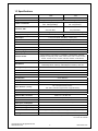
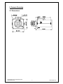
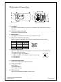
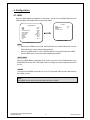
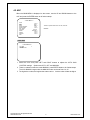
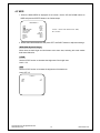
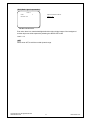
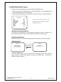
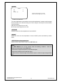
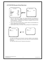
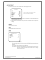
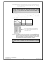
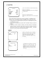
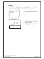
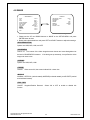
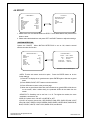
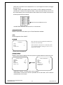
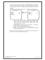
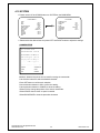
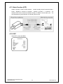
WDE-7680 680 TVL WDE-7610 610 TVL Hyper Wide Dynamic Camera - Effio WDR User Manual Thanks for purchasing our product. Before operating the unit, please read the instructions carefully and keep this manual for future reference. Copyright © 2010. All Rights Reserved. www.okinausa.com i REV122010-V17 Safety Warnings 1. Read this manual carefully before installing the unit Please read this manual first for correct installation and operation. 2. Never install the camera on a ceiling that cannot hold its weight The product may fall down and cause damages. 3. Never install the camera near electric or magnetic fields Install the camera away from TV, radio transmitter, magnet, electric motor, transformer, audio speakers since the magnetic fields generate from above devices would distort the video image. 4. Never install or use the camera in areas exposed to water, oil or gas The water, oil or gas may result in operation failure, electric shock or fire. Do not use this unit near water-for example, near a bath tub, wash bowl, kitchen sink, or laundry tub, in a wet basement, near a swimming pool, in an unprotected outdoor installation, or any area which is classified as a wet location. 5. Never face the camera toward the sun Direct sunlight or severe ray may cause fatal damage to sensor and internal circuit. 6. Power Cord Protection Touching the wet power cord with hands or touching the power cord with wet hands may result in electric shock. Power supply cords should be routed so that they are not likely to be walked on or pinched by items placed upon or against them, playing particular attention to cords and plugs, convenience receptacles, and the point where they exit from the appliance. 7. Attachments Do not use attachment not recommended by the product manufacturer as they may cause hazards. 8. Object and Liquid Entry Never push objects of any kind into this product through openings as they may touch dangerous voltage points or short-out parts that could result in a fire or electric shock. Never spill liquid of any kind onto the product. 9. Do not operate the camera in environments where the temperature, humidity or power source is beyond the specified ones Use the camera in suitable environments where the temperature is within -10°C~50°C and humidity below 90%. Use the input power source as the specifications listed. Copyright © 2010. All Rights Reserved. www.okinausa.com ii REV122010-V17 10. Cleaning Unplug the unit from the outlet before cleaning. Do not use liquid cleaners or aerosol cleaners. Use a damp cloth for cleaning. 11. Never disassemble the camera nor put impurities in it Disassembly or impurities may result in trouble or fire. 12. Stop using when the product emits smoke or abnormal heat 13. Servicing Do not attempt to repair this unit yourself as opening or removing covers may expose you to dangerous voltage or other hazards. Refer all servicing to qualified service personnel. 14. Retain Instructions THE SAFETY AND OPERATING INSTRUCTIONS SHOULD BE RETAINED FOR FUTURE REFERENCE. Warranty OKINA USA products are covered under warranty for one year from the date of purchase. The warranty will automatically be voided if any of the following occurs: 1. Camera sticker is removed If the camera sticker is removed, we will not be able to confirm any information regarding when and where the product was purchased. We have no other way to verify the purchase record without the serial number on the camera sticker; therefore, it should not be removed. 2. Camera is modified in any way If the camera is scratched, damaged, or modified in a manner not described in this manual, the warranty will be voided immediately. It is the customer’s responsibility to keep the camera in good condition. 3. Video or power cable is cut The video cable and the power cable should not be tampered with. Cutting or modifying of the cables will result in termination of the warranty. NOTE: The information in this manual was up-to-date when published. The manufacturer reserves the right to revise and improve its products. All specifications are therefore subject to change without notice. Copyright © 2010. All Rights Reserved. www.okinausa.com iii REV122010-V17 Table of Contents 1. INTRODUCTION .............................................................................................................................. 1 1.1 MAIN FEATURES ............................................................................................................................ 1 1.2 CONTENT LIST ............................................................................................................................... 1 1.3 SPECIFICATIONS ............................................................................................................................ 2 2. CAMERA OVERVIEW ...................................................................................................................... 3 2.1 DIMENSIONS.................................................................................................................................. 3 2.2 DESCRIPTION OF CAMERA PARTS .................................................................................................... 4 3. OSD OPERATION ............................................................................................................................ 6 3.1 OSD CONTROL BUTTONS............................................................................................................... 6 3.2 OSD OPERATION........................................................................................................................... 7 4. CONFIGURATION ............................................................................................................................ 8 4.1 LENS ........................................................................................................................................... 8 4.2 AGC............................................................................................................................................. 9 4.3 WDR.......................................................................................................................................... 10 4.4 WHITE BALANCE CONTROL ...................................................................................................... 12 4.5 2D &3D NR (DYNAMIC NOISE REDUCTION) ................................................................................... 14 4.6 DAY/NIGHT ............................................................................................................................... 16 4.7 SHUTTER ................................................................................................................................. 20 4.8 IMAGE....................................................................................................................................... 22 4.9 EFFECT .................................................................................................................................... 23 4.10 SYSTEM ................................................................................................................................. 26 4.11. BALUN FUNCTION (UTP) ........................................................................................................... 28 4.12. EXIT ....................................................................................................................................... 28 Copyright © 2010. All Rights Reserved. www.okinausa.com iv REV122010-V17 1. Introduction WDE-7680 and WDE-7610 are built with Sony’s latest image processor, this super-wide dynamic camera has the capability of achieving resolutions of over 680TVL or 610TVL respectively. The features include 2-D and 3-D noise reduction, sense up, spot removal, strong-light suppression, intelligent motion, face detection and OSD functions. The camera also comes with 256x digital zoom, an intelligent auto exposure compensation system and an RS-485 remote control. WDE-7680 / WDE-7610 reproduces nearly perfect images like no other. 1.1 Main Features WDE-7680 Color: 680 TVL, B/W: 700 TVL Powerful 510x WDR (54dB) WDE-7610 Color: 610 TVL, B/W: 630 TVL Powerful 256x WDR (53dB) 1/3" Hyper Wide Dynamic Color Camera, Effio WDR DSP Color: 0.03 Lux @ F1.0, B/W: 0.01 Lux @ F1.0, Sense-up: 0.0001 [email protected] Multi-Language OSD Control / RS485 Control Ideal for Backlight Environments 2D/3D Noise Reduction & Sense Up (512x) Functions High Contrast Images Face Detection of up to 4 faces E-zoom Function (1~256x) Advanced Motion Detection Function Polygonal Mosaic Privacy Mask Freeze / Timer Clock 12V DC / 24V AC, 3.0W 1.2 Content List One (1) WDE-7680 or WDE-7610 camera One (1) Female DC Connector One (1) CS Mount Ring One (1) DC Plug One (1) Allen Wrench One (1) Warning Sign Sticker One (1) User Manual One (1) CD * For any returns, please include all components listed above with original packaging in Resalable Condition. Absolutely No Returns will be accepted if any component is missing/damaged or if any cable is cut or tampered with. Copyright © 2010. All Rights Reserved. www.okinausa.com 1 REV122010-V17 1.3 Specifications PIC Model Image Sensor Number of Total Pixels Resolution ; DSP Minimum Illumination Wide Dynamic Range Video Output T-408 T-410 WDE-7680 WDE-7610 1/3" Sony 760H Double-speed (Double-density) CCD NTSC: 1028(H)x508(V) PAL: 1024(H)x596(V) NTSC: 811(H)x508(V) Color: 680 TVL, B/W: 700 TVL Color: 610 TVL, B/W: 630 TVL Sony Effio WDR Sony Effio WDR PAL: 795(H)x596(V) Color: 0.03 Lux @ F1.0; B/W: 0.01 Lux @ F1.0; Sense-up: 0.0001 Lux @ F1.0 510x Normal Camera (54dB) 256x Normal Camera (53dB) 1.0Vp-p Composite, 75Ω (BNC), S-Video (Y/C) More than 52dB (AGC off, Weight on) Signal to Noise Ratio 0.45 Gamma Correction Menu OSD Control or by RS485 Control Title TITLE (LOCATION) Synchronizing System INTERNAL / LINE CLOCK Digital Day&Night Mode COLOR / B&W / AUTO / EXT / SCHEDULE Electronic Shutter AUTO(1/50(60)~1/100,000sec.) / SCHEDULE or DAY&NIGHT / MANUAL: 1/50(60), FL 1/120(100), 1/200, 1/250, 1/350, 1/500, 1/750, 1/1,000, 1/1,500, 1/2,000, 1/3,000, 1/4,000, 1/10,000, 1/30,000, 1/60,000, 1/100,000 sec. AUTO / MANUAL / OFF Automatic Gain Control White Balance ATW / AWB / AWC (Push Lock) / MANUAL / OUTDOOR(1800°K~10500°K) / INDOOR(4500°K~8500°K) / ANTI CR WDR / BLC / OFF Back Light Compensation ON / OFF Flickerless 3D / 2D Dynamic Noise Reduction AUTO (Limit x2~x512) / OFF Sense Up 4 Face Detection Face Detection Language ENGLISH / TRADITIONAL CHINESE / SIMPLIFIED CHINESE X1~x256, Pan / Tilt Adjustable E-Zoom Motion Detection ; Privacy ON / OFF (24x16 Zones, Alarm) ; ON / OFF (16 Zones Programmable, Polygonal Mosaic) Year/Month/Date, Hour/Minute/Second Timer Clock Camera Control Interface RS485 Interface OSD Control by Pelco-D, Pelco P VIDEO / DC ; D4 IRIS Jack Automatic IRIS ; Connector C / CS mount (With Adaptor) Lens Mount Not Included Lens Power Input ; Consumption Operation ; Storage Temp. 12V DC / 24V AC (10.8~39V DC / 24V AC) ; 3.0W 14˚F~122˚F ; -4˚F~140˚F Maximum: RH80% ; RH90% Operation ; Storage Humidity Dimensions / -10˚C~50˚C ; -20˚C~60˚C 2.36”(W) x 1.97”(H) x 4.68”(L) / 60mm(W) x 50mm(H) x 119mm(L) 0.77 lbs Net Weight / 350g * Specifications are subject to change without notice. PAL version also available. Copyright © 2010. All Rights Reserved. www.okinausa.com 2 REV122010-V10 2. Camera Overview 2.1 Dimensions IRIS Copyright © 2010. All Rights Reserved. www.okinausa.com 3 REV122010-V17 2.2 Description of Camera Parts AC24V (1) Lens Mount This mount is used to install a CS-mount lens. CS-adaptor ring is required when using a C mount lens. (2) Camera Mounting Screw Holes Screw hole for mounting the camera. (3) Mount Adaptor The adaptor can be attached onto the top or the bottom of the unit. (4) Auto Iris Lens Connector (4-pin type) The lens connector supplies the auto-iris lens (not supplied) with DC control signal. PIN NO. 1 2 3 4 VIDEO DC + 12V NC IRIS GND DC CONTROL CONTROL + DRIVE + DRIVE - (5) S-Video Output Terminal Separate Y (brightness) and C (color) signal are outputs from this terminal to obtain better video quality at a video monitor. 1. C signal: 0.3V (p-p), 75Ω, unbalance 2. Y signal: 1.0V (p-p), 75 Ω, unbalance, negative synchronizing 3. C signal Ground 4. Y signal Ground (6) Iris Mode Selection Switch Select DC or VIDEO mode according to the lens. (7) OSD Control Buttons ENTER button UP & DOWN buttons LEFT & RIGHT buttons (8) Video Connector Video can be outputted via this BNC connector (75Ω). Copyright © 2010. All Rights Reserved. www.okinausa.com 4 REV122010-V17 (9) Communication Connectors 1. RS485+ 2. RS4853. Day & Night External Input (controlled by external infrared illuminator) 4. Day & Night Output 5. Alarm Out 6. Ground (10) Power Input Indicator Light When the camera is connected to a power source, the indicator light will be on. (11) RS485 Terminal Impedance Switch Set the first and the last equipment terminal impedances as 120Ω and set the rest parallel connection equipment in the middle as HiZ to obtain the best transmitting status. (12) Power Input Terminal Connect the power input of 12V DC / 24V AC (10.8~39V DC / 24V AC). Copyright © 2010. All Rights Reserved. www.okinausa.com 5 REV122010-V17 3. OSD Operation 3.1 OSD Control Buttons ① UP Use this button to move the cursor upwards to the desired item. ② RIGHT Use this button to move the cursor to the right to select or to adjust the parameters of the selected item. The parameter increases when the right button is pressed. ③ DOWN Use this button to move the cursor downwards to the desired item. ④ LEFT Use this button to move the cursor to the left to select or to adjust the parameters of the selected item. The parameter decreases when the left button is pressed. ⑤ ENTER Use this button to display the main menu, to confirm and to enter the submenus when they’re available. Items with “<┘” symbol in the end contain sub-menus. For further settings of those items, select the desired item with the button c or d and press the ENTER button to bring up the sub-menu and edit. Copyright © 2010. All Rights Reserved. www.okinausa.com 6 REV122010-V17 3.2 OSD Operation ** MAIN MENU ** LENS AGC WDR WHITE BALANCE 2DNR & 3DNR DAY / NIGHT SHUTTER IMAGE EFFECT SYSTEM EXIT 1. SET<┘ AUTO WDR<┘ ATW SET<┘ COLOR MANUAL<┘ SET<┘ SET<┘ SET<┘ Start to operate the OSD menu Press the ENTER button to bring up the OSD main menu to start operating OSD menus. 2. Select items with the cursor buttons y y 3. Use buttons c and d to move the cursor up and down. Use buttons e and f to switch the modes or to adjust the parameters or the values of the settings. Switch to the sub-menu Items with “<┘” symbol in the end contains sub-menus. For further settings of those items, select the desired item with the button c or d and press the ENTER button to bring up the sub-menu and edit. ** MAIN MENU ** LENS AGC WDR WHITE BALANCE 2DNR & 3DNR DAY / NIGHT SHUTTER IMAGE EFFECT SYSTEM EXIT ** LENS ** SET<┘ AUTO WDR<┘ ATW SET<┘ COLOR MANUAL<┘ SET<┘ SET<┘ SET<┘ LENS BRIGHTNESS SPEED RETURN EXIT DC<┘ 14 0 Sub-Menu Main Menu 4. Return to the previous page Select RETURN and press the ENTER button to return to the previous page. 5. Exit the OSD menu Select EXIT with the button c or d and press the ENTER button to exit the OSD menu. Copyright © 2010. All Rights Reserved. www.okinausa.com 7 REV122010-V17 4. Configuration 4.1 LENS When the MAIN MENU is displayed on the screen, use the UP and DOWN buttons to the LENS and press the ENTER button to do further setups. ** LENS ** ** MAIN MENU ** LENS AGC WDR WHITE BALANCE 2DNR & 3DNR DAY / NIGHT SHUTTER IMAGE EFFECT SYSTEM EXIT LENS BRIGHTNESS SPEED RETURN EXIT SET<┘ AUTO WDR<┘ ATW SET<┘ COLOR MANUAL<┘ SET<┘ SET<┘ SET<┘ DC<┘ 14 0 Sub-Menu of LENS Main Menu *LENS y When the DC LENS is in use, push IRIS SWITCH on the control board to DC, and the LENS status on the menu will be displayed as DC. y When the VIDEO LENS is in use, push IRIS SWITCH on the control board to VIDEO, and the LENS status on the menu will be displayed as VIDEO. *BRIGHTNESS When the LENS MENU is displayed on the screen, use the UP and DOWN buttons to the BRIGHTNESS and use LEFT and RIGHT buttons to adjust the screen brightness from level 0 to 63. *SPEED The range of the SPEED can be set from -31 to 32. The speed of DC Lens is in direct ratio to the number you set. NOTE: The SPEED function will not work when the LENS set to VIDEO. Copyright © 2010. All Rights Reserved. www.okinausa.com 8 REV122010-V17 4.2 AGC When the MAIN MENU is displayed on the screen, use the UP and DOWN buttons to the AGC and press the ENTER button to do further setups. ** MAIN MENU ** LENS AGC WDR WHITE BALANCE 2DNR & 3DNR DAY / NIGHT SHUTTER IMAGE EFFECT SYSTEM EXIT SET<┘ AUTO WDR<┘ ATW SET<┘ COLOR MANUAL<┘ SET<┘ SET<┘ SET<┘ There’re 3 options under AGC: AUTO, OFF and MANUAL. *AGC MAX ** AGC MANUAL** AGC MAX RETURN EXIT 3 1. Select the AGC and press LEFT and RIGHT buttons to adjust the AUTO GAIN CONTROL settings. Options are AUTO, OFF, and MANUAL. 2. There’s a submenu under the mode MANUAL, press ENTER button to do further setups. The AGC MANUAL range under the MANUAL mode can be set from 0 to 15. 3. The higher the number, the brighter the screen can be. And the noise will also be higher. Copyright © 2010. All Rights Reserved. www.okinausa.com 9 REV122010-V17 4.3 WDR 1. When the MAIN MENU is displayed on the screen, use the UP and DOWN buttons to WDR and press the ENTER button to do further setups. ** MAIN MENU ** LENS AGC WDR WHITE BALANCE 2DNR & 3DNR DAY / NIGHT SHUTTER IMAGE EFFECT SYSTEM EXIT SET<┘ AUTO WDR<┘ ATW SET<┘ COLOR MANUAL<┘ SET<┘ SET<┘ SET<┘ There’re 3 modes under WDR function: WDR, BLC, and OFF. 2. Please select the desired item and press LEFT and RIGHT buttons to adjust the settings. *WDR (Wide Dynamic Range) When there are both bright and dark areas at the same time, selecting this mode makes both areas distinctive. *LEVEL Use the LEVEL function to decrease the brightness of the bright area. Level: 1~32 *XDR Use the LEVEL function to increase the brightness of the dark area. Level: OFF~15 * * WDR ** LEVEL XDR EXIT 18 OFF Sub-Menu under WDR mode. Copyright © 2010. All Rights Reserved. www.okinausa.com 10 REV122010-V17 *BLC (Back Light Compensation) ** BLC ** LEVEL RETURN Options under this mode are 6 EXIT Level : 1~14. Sub-Menu under BLC mode. Even when there is a massive backlight behind the object, bright images of the background and the object can still be captured by selecting the BACKLIGHT mode. Level: 1~14 *OFF When set as OFF, there’ll be no wide dynamic range. Copyright © 2010. All Rights Reserved. www.okinausa.com 11 REV122010-V17 4.4 WHITE BALANCE Control The screen color can be adjusted by using the WHITE BALANCE function. 1. Please use the UP and DOWN buttons to WHITE BALANCE on the MAIN MENU and press the ENTER button to do further setups. 2. Please select the desired item and press LEFT and RIGHT buttons to adjust the settings. ** MAIN MENU ** LENS AGC WDR WHITE BALANCE 2DNR & 3DNR DAY / NIGHT SHUTTER IMAGE EFFECT SYSTEM EXIT SET<┘ AUTO WDR<┘ ATW SET<┘ COLOR MANUAL<┘ SET<┘ SET<┘ SET<┘ There’re 6 modes under this function: ATW, AWB, AWC (Push Lock), MANUAL, OUTDOOR, INDOOR and .ANTI CR. *ATW (Auto Tracking White Balance) This mode can be used within the color temperature range from 1800°K to 10500°K (e.g., around fluorescent lights, outdoors, around sodium vapor lamps or inside tunnels). *AWB (Auto White Balance) Select this to allow the camera automatically adjust the white balance under all conditions. * AWC (Push Lock) **AWC ** PRESS AND HOLD ENTER BUTTON UNTIL AWC COMPLETED. Follow the instructions shown on the screen to complete the setting. **AWC ** COMPLETED PRESS ENTER RETURN Sub-Menu under AWC mode. Sub-Menu under AWC mode. To find the optimal setting for the current luminance environment in this mode, point the camera towards a sheet of white paper and press the ENTER button. Whenever the condition changes, readjust it. Copyright © 2010. All Rights Reserved. www.okinausa.com 12 REV122010-V17 *MANUAL **MWB ** RED BLUE RETURN 30 25 EXIT RED color value ranges from 0 to 255. BLUE color value ranges from 0 to 255. Sub-Menu under MWB mode. The manual adjustment mode enables a more precise adjustment. Increase and/or decrease the red and blue color values according to the color changes of the object to set the suitable color temperature. RED color vale ranges from 0 to 255. BLUE color value ranges from 0 to 255. *OUTDOOR Select this when the color temperature is around 6300°K. *INDOOR Select this when the color temperature is around 3200°K (when surrounded by sodium lights). *ANTI CR (Color rolling suppression) Select to set the white balance mode to the ANTI CR mode. NOTE: The White Balance can not fully function under the following conditions. following occurred, please select AWC Mode. When the < When there’s a higher temperature surrounded the object. < When there’s darkness surrounded the object. < When there’s a fluorescent light surrounded the object or where the light changes all the time. Copyright © 2010. All Rights Reserved. www.okinausa.com 13 REV122010-V17 4.5 2D &3D NR (Dynamic Noise Reduction) ** MAIN MENU ** LENS AGC WDR WHITE BALANCE 2DNR & 3DNR DAY / NIGHT SHUTTER IMAGE EFFECT SYSTEM EXIT ** 2DNR & 3 DNR ** SET<┘ AUTO WDR<┘ ATW SET<┘ COLOR MANUAL<┘ SET<┘ SET<┘ SET<┘ 2DNR 3DNR RETURN ON<┘ ON<┘ EXIT Sub-Menu under 2DNR & 3DNR mode. 1. When the noise level is reduced, the camera performance can apparently be improved. When recording digitally, the image file size can be lessened by selecting the noise reduction. As the level of gain changes, the background noise in the low light level decreases automatically. 2. Please use the UP and DOWN buttons to 2DNR & 3DNR on the MAIN MENU and press the ENTER button to do further setups. 3. Please select the mode you would like to set by pressing the UP and DOWN buttons. *2DNR ** 2DNR** ** 2DNR & 3 DNR ** 2DNR 3DNR RETURN LEVEL RETURN ON<┘ ON<┘ 3 EXIT EXIT Sub-Menu under the 2DNR mode Sub-Menu under 2DNR & 3DNR mode. •ON: When the 2DNR is set to ON, there’s a submenu available for level adjustment, ranged from 1 to 4. The higher the level, the more noise can be reduced but sharpness will decrease. •OFF: When the 2DNR is set to OFF. Noise will not be reduced. Copyright © 2010. All Rights Reserved. www.okinausa.com 14 REV122010-V17 *3DNR ** 3DNR** LEVEL RETURN 3 EXIT Sub-Menu under the 3DNR mode •ON: When the 3DNR is set to ON, there’s a submenu available for level adjustment, ranged from 0 to 15. The higher the level, the more noise can be reduced but moving objects be blurred in low illumination condition. •OFF: When the 3DNR is set to OFF. Noise will not be reduced. Copyright © 2010. All Rights Reserved. www.okinausa.com 15 REV122010-V17 4.6 DAY/NIGHT The camera can be set in Color or B/W mode in the Day/Night function. ** MAIN MENU ** LENS AGC WDR WHITE BALANCE 2DNR & 3DNR DAY / NIGHT SHUTTER IMAGE EFFECT SYSTEM EXIT SET<┘ AUTO WDR<┘ ATW SET<┘ COLOR MANUAL<┘ SET<┘ SET<┘ SET<┘ There’re 5 modes under this function: COLOR, B&W, AUTO, EXTERNAL, SCHEDULE. 1. Please use the UP and DOWN buttons to DAY/NIGHT on the MAIN MENU and press the ENTER button to enter. 2. Please select the desired item and press LEFT and RIGHT buttons to adjust the settings. *COLOR The COLOR / DAY mode. *B&W The BLACK & WHITE / NIGHT mode. *AUTO ** DAY/NIGHT AUTO ** LIVE LEVEL DAY->NIGHT NIGHT->DAY DELAY TIME NIGHT OUTPUT BURST EXIT 20 3 8 5 5V ON Sub-Menu under the DAY / NIGHT AUTO mode The camera will switch to DAY/Color mode or NIGHT/B&W mode according to the set value. •LIVE LEVEL: This indicates the current light level. •DAYÆNIGHT: When the camera detects the current light level is lower than the set value, it’ll switch from DAY mode to NIGHT mode. Settings can be set from 6 to 32. Copyright © 2010. All Rights Reserved. www.okinausa.com 16 REV122010-V17 •NIGHTÆDAY: When the camera detects the current light level is higher than the set value, it’ll switch from NIGHT mode to DAY mode. Settings can be set from 1 to 27. NOTE: The setting differences between DAY ÆNIGHT and NIGHTÆDAY should be more than 5, or the camera will keep switching from DAY ÆNIGHT and NIGHTÆDAY constantly. •DELAY TIME: Sometimes there’s only a sudden and short light level change. Delay time can be set to avoid switching too fast. The camera will switch the mode after the set DELAY TIME passed. DELAY TIME can be set from 0 to 255 seconds. •NIGHT OUTPUT OUTPUT DNO SYSTEM COLOR B&W GND 5V 5V GND GND 5V When it’s under B/W mode, the infrared illuminator can be triggered to be on, via DNO pin of the communication connector. •BURST : Turn the BURST function off to reduce the color noise under B&W mode. However, not every DVR machines can receive video signals without the color burst signals. If the camera cannot switch back to COLOR mode from B&W mode, please turn the BURST function on. NOTE: The BURST function is adjustable under B&W, EXTERNAL and SCHEDULE mode. Copyright © 2010. All Rights Reserved. www.okinausa.com 17 REV122010-V17 *EXTERNAL ** DAY/NIGHT EXT ** NIGHT INPUT BURST RETURN EXIT LOW ON HIGH :3~12V OR OPEN LOW : GND Sub-Menu under the DAY / NIGHT EXTERNAL mode EXTERNAL mode allows the user to switch the DAY/NIGHT mode with external signals. For example, you can synchronize the DAY/NIGHT mode between the camera and the infrared LED illuminator. For the camera with the light sensor, it is suggested to set the DAY/NIGHT mode to EXTERNAL to ensure the best result. NIGHT INPUT: Select input level. LOW : It will be the COLOR mode if the input signal is HIGH. On the contrary, it will be the B&W mode. HIGH : It will be the B&W mode if the input signal is HIGH. On the contrary, it will be COLOR mode. HIGH :3~12V or OPEN LOW : GND INPUT SYSTEM DNI HIGH LOW LOW HIGH COLOR B&W B&W COLOR When the external infrared illuminator is in use, the camera can switch to COLOR or B/W mode, via DNI pin of the communication connector. Copyright © 2010. All Rights Reserved. www.okinausa.com 18 REV122010-V17 *SCHEDULE ** DAY / NIGHT SCHEDULE ** DAY / NIGHT NIGHT / DAY RETURN •18 :00 •06 :00 EXIT Sub-Menu under the DAY / NIGHT SCHEDULE mode When the SCHEDULE function is selected, the camera will automatically switch between COLOR and B&W modes according to the preset time. •DAY/NIGHT: set the timing to switch from DAY/COLOR to NIGHT/B&W. •NIGHT/DAY: set the timing to switch from NIGHT/B&W to DAY/COLOR. Copyright © 2010. All Rights Reserved. www.okinausa.com 19 REV122010-V17 4.7 SHUTTER There’re 3 modes repetitively for 2 situations under this function: ** MAIN MENU ** LENS AGC WDR WHITE BALANCE 2DNR & 3DNR DAY / NIGHT SHUTTER IMAGE EFFECT SYSTEM EXIT SET<┘ AUTO WDR<┘ ATW SET<┘ COLOR MANUAL<┘ SET<┘ SET<┘ SET<┘ MANUAL, AUTO, DAY/NIGHT (when the DAY / NIGHT function has set to AUTO, EXTERNAL, or SCHEDULE mode), or MANUAL, AUTO, SCHEDULED SHUTTER (when the DAY / NIGHT function has set to COLOR or B&W mode.) When the DAY / NIGHT function has set to AUTO, EXTERNAL, or SCHEDULE mode: MANUAL, AUTO, and DAY/NIGHT modes are available under the SHUTTER function. 1. Please use the UP and DOWN buttons to SHUTTER on the MAIN MENU and press the ENTER button to enter. 2. Please select the desired item and press LEFT and RIGHT buttons to adjust the settings. 3. SENSE-UP is used to maintain a brilliant, vivid screen image by automatically detecting changes in the level of light under low light level conditions. Select the desired item and press LEFT and RIGHT buttons to adjust the settings. The options are x2, x4, x8, x16, x32, x64, x128, x256, x512, and OFF. *MANUAL There‘re 16 speed types under the SHUTTER ** SHUTTER MANUAL ** SHUTTER SENSE UP RETURN EXIT MANUAL mode: 1/50(60), 1/120(100), 1/200, 1/250, 1/50 X4 1/350, 1/500, 1/750, 1/1000, 1/1500, 1/2000, 1/3000, 1/4000, 1/10000, 1/30000, 1/60000, 1/100000 SENSE UP only works when the Shutter is at PAL: 1/50 (NT:1/60). *AUTO ** SHUTTER AUTO ** MIN MAX SENSE UP RETURN EXIT The MINIMUM and the MAXIMUM of the SHUTTER 1/50 1/10000 X4 SPEED can be set under AUTO mode. The MINIMUM can be set from 1/50(60) to 1/60000 and the MAXIMUM can be set from 1/120 (100) to 1/100000. SENSE UP only works when the Shutter is at PAL: 1/50 (NT:1/60). *DAY / NIGHT Copyright © 2010. All Rights Reserved. www.okinausa.com 20 REV122010-V17 *DAY/NIGHT When the DAY / NIGHT function is set to AUTO, EXTERNAL, or SCHEDULE mode, you can set DAY SHUTTER and NIGHT SHUTER individually. ** SHUTTER D/N ** DAY SHUTTER NIGHT SHUTTER RETURN EXIT 1/50 1/1000 The DAY SHUTTER and the NIGHT SHUTTER can be set in 16 steps.. *SCHEDULED SHUTTER ** SCHEDULED SHUTTER ** NO. TIME SHUTTER 1. 2. 3. 4. 00:00 06:00 12:00 18:00 RETURN NO. 2. EXIT There’re 16 speed types to choose from. Shutter can be changed according to the set schedule; up to 4 1/50 1/120 1/250 1/500 different schedules can be set. The current status shows the actual time and the working shutter speed. STATUS TIME SHUTTER 10:16 1/120 Copyright © 2010. All Rights Reserved. www.okinausa.com 21 REV122010-V17 4.8 IMAGE ** IMAGE ** ** MAIN MENU ** LENS AGC WDR WHITE BALANCE 2DNR & 3DNR DAY / NIGHT SHUTTER IMAGE EFFECT SYSTEM EXIT HIGH RESOLUTION SHARPNESS CHROMA FREEZE MIRROR POS./NEG. RETURN EXIT SET<┘ AUTO WDR<┘ ATW SET<┘ COLOR MANUAL<┘ SET<┘ SET<┘ SET<┘ HIGH 10 MID OFF NORMAL OFF Sub-Menu under the Image Function 1. Please use the UP and DOWN buttons to IMAGE on the SETUP MENU and press ENTER button to enter. 2. Please select the desired item and press LEFT and RIGHT buttons to adjust the settings. *HIGH RESOLUTION Options are HIGH, MID, LOW, and OFF. *SHARPNESS Level 0~15. The contour of the video image becomes cleaner and more distinguished as the level of SHARPNESS increases. If the level goes up extremely, it may affect the video image and cause noise. *CHROMA Options are HIGH, MID, LOW. *FREEZE ON/OFF. When set as ON, the screen holds still for a clear view. *MIRROR NORMAL, VERTICAL (vertical rotated), MIRROR (horizontal rotated), and ROTATE (vertical and horizontal rotated). *POS. / NEG. ON/OFF. Negative/Positive Reversal. function. Copyright © 2010. All Rights Reserved. www.okinausa.com Select ON or OFF to enable or disable this 22 REV122010-V17 4.9 EFFECT ** MAIN MENU ** LENS AGC WDR WHITE BALANCE 2DNR & 3DNR DAY / NIGHT SHUTTER IMAGE EFFECT SYSTEM EXIT ** EFFECT ** MOTION DETECTION FACE DETECTION VPS E-ZOOM PRIVACY MASK EXIT SET<┘ AUTO WDR<┘ ATW SET<┘ COLOR MANUAL<┘ SET<┘ SET<┘ SET<┘ OFF OFF ON OFF OFF 1. Please use the UP and DOWN buttons to EFFECT on the MAIN MENU and press ENTER button to enter. 2. Please select the desired item and press LEFT and RIGHT buttons to adjust the settings. * MOTION DETECTION Options are ON/OFF. When MOTION DETECTION is set as ON, there’re several submenus under this function: ** MOTION DETECT ** AREA SENSITIVITY DISPLAY COLOR SIZE FRAME ALARM OUT ALARM TIME RETURN EXIT ** MOTION AREA ** ENTER : AREA ON/OFF D/R/L : MOVE CURSOR UP : RETURN SET<┘ 30 COLOR 5 3 OFF ON 5 BLINK FAST : AREA ON BLINK SLOW : AREA OFF Sub-Menu under the AREA option •AREA: There’re sub-menus under this option. Press the ENTER button to do the further settings. 1) Press SET to display the on-guard areas or press ENTER again to hide the on-guard areas. 2) Press DOWN, RIGHT, LEFT buttons to do the selection. 3) Press UP button to return to the previous page. 4) When the on-guard block blinks fast, this indicates the on-guard AREA will be shown on the screen; while it blinks slowly, the protected AREA will be hided from the screen. •SENSITIVITY: Sensitivity can be set from 1 to 32. The higher the number, the more sensible the camera can be. •DISPLAY: Options are in COLOR, in INVERSE or OFF. •COLOR: 16 colors to choose from, RED PURPLE, PINK, RED, DARK YELLOW, LIGHT YELLOW, LIGHT GREEN, GRASS GREEN, DARK GREEN, WATER BLUE, BABY BLUE, BLUE, PURPLE, WHITE, LIGHT GRAY, DARK GRAY, and BLACK. Copyright © 2010. All Rights Reserved. www.okinausa.com 23 REV122010-V17 •SIZE: Size of the block can be adjusted from 1 to 15; the higher the number, the bigger the block can be. •FRAME: Choose ON to display block only in frame, or OFF to display a whole block. •ALARM OUT: Choose ON to output the alarm; connect the alarm device to the ALO of the communication port on the rear panel so that the alarm can be output. Be sure to turn off all the power before connecting. Connect the ALARM terminal here. •ALARM TIME: Alarm time can be set from 1 to 60 seconds. * FACE DETECTION ON/OFF, when set as ON, there’re up to 4 Faces Detections available. * VPS Virtual Progressive Scan ON/OFF. * E-ZOOM When VPS set as ON, this E-ZOOM mode is available, press ** E-ZOOM ** RATIO E PAN E TILT RETURN Enter button to do further setups. 1 0 0 EXIT Options are RATIO 1x~256x (zoom in 1 to 256 times), E PAN -15~16 (horizontal zoomed-in viewing), and E TILT -15~16 (vertical zoom-in viewing). Sub-Menu under the E-ZOOM mode * PRIVACY MASK ON/OFF, when PRIVACY MASK is set as ON, there’re several submenus under this mode: ** AREA 1 MASK EDIT ** ** PRIVACY MASK ** AREA SEL AREA MODE AREA COLOR MOSAIC SIZE RETURN EXIT TOP BOTTOM LEFT RIGHT ANGLE TOP ANGLE BOTTOM RETURN EXIT 1<┘ 30 SET<┘ SET<┘ 4 30 80 40 100 0 0 •AREA SEL: There’re 1-16 areas which can be masked. •AREA MODE: Choose ON to show the protected area on the screen, OFF to hide the protected area on the screen. Copyright © 2010. All Rights Reserved. www.okinausa.com 24 REV122010-V17 •AREA: There’re sub-menus under this mode. Press ENTER button to do further setups. Set the area size and shape here. The bigger the number, the bigger the block size can be. Polygon shapes can also be created by adjusting ANGLE TOP and ANGLE BOTTOM. •COLOR: There’re sub-menus under this section. Select SET<┘ to do further setups. ** PRIVACY MASK ** AREA SEL AREA MODE AREA COLOR MOSAIC SIZE RETURN EXIT ** MASK COLOR ** COLOR TRANSPARENCY MOSAIC FRAME RETURN EXIT 1<┘ 30 SET<┘ SET<┘ 4 1 6 OFF 2 1) COLOR: There’re 16 colors available. RED PURPLE, PINK, RED, DARK YELLOW, LIGHT YELLOW, LIGHT GREEN, GRASS GREEN, DARK GREEN, WATER BLUE, BABY BLUE, BLUE, PURPLE, WHITE, LIGHT GRAY, DARK GRAY, and BLACK. 2) TRANSPARENCY: the block can also be transparent. The bigger the number, the more transparent the block can be. 3) MOSAIC: ON/OFF. To display the block in mosaic or not. 4) FRAME: Frame thickness can be set. The bigger the number, the thicker the frame of the block can be. •MOSAIC SIZE: The mosaic density can be set; the bigger the number the vaguer the block can be. Use LEFT and RIGHT buttons to adjust. Copyright © 2010. All Rights Reserved. www.okinausa.com 25 REV122010-V17 4.10 SYSTEM 1. Please use the UP and DOWN buttons to SYSTEM on the MAIN MENU. ** MAIN MENU ** LENS AGC WDR WHITE BALANCE 2DNR & 3DNR DAY / NIGHT SHUTTER IMAGE EFFECT SYSTEM EXIT ** SYSTEM ** CAMERA TITLE DATE/TIME COMM SYNC LANGUAGE FIRMWARE RESTORE EXIT SET<┘ AUTO WDR<┘ ATW SET<┘ COLOR MANUAL<┘ SET<┘ SET<┘ SET<┘ OFF OFF SET<┘ INT ENGLISH 0.06 SET<┘ 2. Please select the desired item and press LEFT and RIGHT buttons to adjust the settings. * CAMERA TITLE 0 1 2 3 4 5 6 7 8 9 A B CD E F GHI J KL M NOP QRST UVWXYZ a b c d e f g h i j k l m n o p q r s t u v w x y z . , : ‘ “ / # * = ( ) < > - - - - - - - - - - - - - --SPACE ACKSPACE POSI COPY OK CANCEL Numbers, letters and symbols can be used for naming the camera title. *Use direction buttons to select the desired character. *Press SET button to confirm each selection. *Use the direction buttons to OK to confirm the setting. *Use the direction buttons to CANCEL to abort the setting. *Select POSI to change the position of the shown camera title. *Select SPACE when a blank / a space is needed. *Select BACKSPACE to clear the precedent character. Copyright © 2010. All Rights Reserved. www.okinausa.com 26 REV122010-V17 * DATE / TIME ** DATE / TIME ** TIME DATE FORMAT RETURN EXIT 10:00:00 10:01:01 YY:MM:DD HH: Hour, MM: Minute, SS: Second, YY: Year, MM: Month, DD: Date. Select ON/OFF to show/hide the Date/Time on the screen. * COMM There’re sub-menus under this section. Select SET<┘ to do further setups. 1. The CAM ID, PROTOCOL and BAUD RATE will be displayed for the first five seconds on boot. 2. Changes made to the CAM ID, PROTOCOL and BAUD RATE will only take effect after you exit the COMM page. This is to prevent the camera from unexpected disconnecting caused by remote access. •CAM ID: 1~1024 •DISP CAMERA ID: ON/OFF (*Select ON/OFF to show/hide the CAM ID on the screen.) •PROTOCOL: PELCO-D, PELCO-P •BAUD RATE: 2400/4800/9600/19200/38400 * SYNC •INT: Internal synchronization •LL: External line-lock synchronization: when LL is selected, press the ENTER button to confirm. The phase can be set from 0 to 359. * LANGUAGE •ENGLISH •简体中文 •繁體中文 Use the LEFT & RIGHT buttons to select the language preference. * FIRMWARE Please refer to the actual firmware. * RESTORE Please choose CANCEL to exit; once the CONTINUE is chosen, all the settings will be restored to the defaults except for the following: CAM ID, PROTOCOL, BAUD RATE and LANGUAGE. Copyright © 2010. All Rights Reserved. www.okinausa.com 27 REV122010-V17 4.11. Balun Function (UTP) A Balun's function is used on these cameras. It would normally require 3 terminals (Video + Power + RS485) to succeed a connection. However, via Balun, 1 is sufficient. The cameras OSD can be used and controlled remotely via RS485 communication port. The most important thing is transmission can still stay clear and true. 4.12. EXIT Select EXIT to leave the MENU. ** MAIN MENU ** LENS AGC WDR WHITE BALANCE 2DNR & 3DNR DAY / NIGHT SHUTTER IMAGE EFFECT SYSTEM EXIT SET<┘ AUTO WDR<┘ ATW SET<┘ COLOR<┘ MANUAL<┘ SET<┘ SET<┘ SET<┘ Copyright © 2010. All Rights Reserved. www.okinausa.com 28 REV122010-V17