1
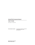
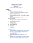
H0300 Event Logger
MODBUS Master
User manual
SELCO A/S
Betonvej 10 - DK-4000 Roskilde
Denmark
Phone: 45 7026 1122 - Fax: 45 7026 2522
E-mail: [email protected]
www.selco.com
Table of Contents
Preface.................................................................................................................................................. 3
Mounting .............................................................................................................................................. 5
DIP switch settings........................................................................................................................... 5
Installation............................................................................................................................................ 6
Initialisation ..................................................................................................................................... 6
Entering Surveillance Mode............................................................................................................. 7
Logging Events .................................................................................................................................... 8
Logging to Printer ............................................................................................................................ 9
Acknowledging New Events ............................................................................................................ 9
Stop the siren ................................................................................................................................ 9
Setup mode......................................................................................................................................... 10
Menu structure ........................................................................................................................... 11
On-site configuration ..................................................................................................................... 12
Menu 1: Commands ................................................................................................................... 12
Menu 2: Time / Date .................................................................................................................. 12
Menu 3: Print ............................................................................................................................. 12
Menu 4: Bus ............................................................................................................................... 13
Menu 5: Log ............................................................................................................................... 13
Menu 6: Dimming ...................................................................................................................... 13
Relations ............................................................................................................................................ 14
Security of Logging Functions........................................................................................................... 15
Control of Communication ............................................................................................................ 15
Control of Printer ........................................................................................................................... 15
Control of Data............................................................................................................................... 15
RS232 Terminal ................................................................................................................................. 16
Configuration Commands .................................................................................................................. 16
Set Relation .................................................................................................................................... 17
Delete Relation ............................................................................................................................... 17
Show Relations .............................................................................................................................. 17
Reset Relations ............................................................................................................................... 17
Write Text ...................................................................................................................................... 18
Move Text ...................................................................................................................................... 18
Read Text ....................................................................................................................................... 19
Reset Texts ..................................................................................................................................... 19
Write Time ..................................................................................................................................... 19
Write Setup .................................................................................................................................... 20
Write to Unit .................................................................................................................................. 20
Write a Bit ...................................................................................................................................... 20
Units on Bus ................................................................................................................................... 21
List of Commands .......................................................................................................................... 21
Specifications ..................................................................................................................................... 22
Appendices ......................................................................................................................................... 24
A - Making H0300 “Text-labels”................................................................................................... 24
B - Setting relations from a text-file .............................................................................................. 27
SELCO A/S
H0300 Event Logger
Preface
The SELCO H0300 Logger is a compact stand-alone unit capable of logging events (alarms and
LED states) from the SELCO M1000C Alarm Annunciator, the SELCO M3000 Analog Alarm
Annunciator, the SELCO M4780 Indicator and the SELCO H1500 Indicator.
The H0300 connects to the M1000, M3000, M4780 and the H1500 by the means of a two-wire
RS485 serial communication bus. The maximum length of the bus cable is 1.000 meters; however
various kinds of RS485 repeaters can be used for extension.
The H0300 can survey a total of 63 units and it provides instant visible and audible alarm should the
communication fail to any one of the connected units.
A backlit display is provided for on-site monitoring of the latest 32 events. Each event is logged
with date and time. The display will automatically show both device number, channel number, LED
state and a 32-character descriptive text (instruction).
The user can acknowledge each of the alarms located in the log by using the front facia keyboard.
Four arrow keys are provided for navigation among the events in the memory log. By default the
display will show actual date and time plus the number of unacknowledged events present in the
memory log. The log has a battery backup system to preserve its contents during a possible power
disruption.
A standard parallel printer with a Centronics interface can be connected directly to the H0300. The
printer will provide a hard copy of the log showing every event captured by the H0300. Each event
is logged with date, time, unit number, channel number and a descriptive text. The log will also
register some of changes made to the configuration of the H0300. The correct function of the printer
is continuously surveyed by the H0300. The printer must support 80 characters per line.
The H0300 can also perform an event relay function. The relay function provides the convenient
feature of transmitting a LED indication from one unit to another (through the 2-wire bus
connection). The user can define any number of relations between the LED’s of the units connected
to RS485 bus. Thereby it’s not necessary to hardwire outputs to inputs, as the indication is relayed
over the common two-wire bus connection. It should be noted that some marine classification
societies have special requirements for redundancy of the bus when this feature is used.
Five LED’s are provided on the front facia of the H0300. These LED’s provide visible indication of
alarm status, communication and printer error. A retractable paper label is provided for local
language descriptions. Two LED’s will show the operational status of the H0300.
Revision: 17-09-2007
Page 3 of 27
SELCO A/S
H0300 Event Logger
The H0300 includes a real time clock and calendar. The date and time can be set directly on the
unit. Summer- and winter-times are adjusted automatically (can be disabled). Various logging
functions can also be configured using the front facia LCD and keyboard. Advanced configuration
is done through the built-in RS232 connection using any personal computer with an ANSI terminal
application (e.g. Windows HyperTerminal). Various commands are available, for instance text
descriptions of all events can be copied from the computer's storage to the H0300 using a simple
write-text command.
The H0300 can not function as a slave on the bus, only as master.
In the case of power break, H0300 will hold the data for a period of time:
The internal date/time will be maintained for about 2 weeks, after that the watch will stop
The system parameters (e.g. 32 last event memory buffer, chosen dimming level and others), will be
kept for about a month
The user defined texts are never lost.
Revision: 17-09-2007
Page 4 of 27
SELCO A/S
H0300 Event Logger
Mounting
The SELCO H0300 is a compact unit intended for flush mounting. Dimensions (H x W x D): 96 x
144 x 64 mm.
The H0300 is intended for mounting in a control panel or a switchboard door. The H0300 should be
mounted in such a way that the display is clearly visible, and so that the operator is able to easily
access the keyboard.
Computer based configuration requires access to the rear of the unit (in order to attach the RS232
DB9 plug).
Remember to take into account the depth of the DB9 and DB25 plugs for the RS232 and the
Centronics printer connections when planning the installation.
137 (mm)
144 (mm)
90 (mm )
96 (mm )
The H0300 fits in a cut-out with measurements of 92 x 138 mm. (H x W). The unit is secured with
two fixation clamps mounted on the sides.
54 (mm)
62 (mm )
DIP switch settings
DIPSWITCH no. 1 is always in OFF-mode. This means MASTER MODE.
DIPSWITCH no. 2 is set to ON-position to disable automatic one-hour-shifting of time in winter
and summer period.
DIPSWITCH no. 3 should be ON if H0300 shall be used without printer.
DIPSWITCH no. 4 enables (OFF) or disables (ON) the front plate configuration key (CFG ).
Revision: 17-09-2007
Page 5 of 27
SELCO A/S
H0300 Event Logger
Installation
Before turning to this section, ensure that the H0300 is mounted and connected according to the
directions provided in this manual. Below follows the description of the H0300.
Connect the H0300 to a +24 VDC power supply. Observe that the green PWR LED ignites with
steady light. After power up, the H0300 should acknowledge with the following text in the display.
*Initialisation*
Initialisation
The H0300 will scan the bus for active units during the initialisation procedure. The scan is
conducted by polling each valid address (1 to 63) for its unit type. Active units that provide a valid
response are added to the surveillance list.
A communication error will be issued if more than one unit has been given the same address on the
bus. Such an error will be reported in the display as follows (address 05 is used as an example).
Invalid response
check address 05
To remedy this error it’s necessary to check the named address setting and change it to another
unoccupied address. It is of course important that each unit has a unique address on the bus.
Afterwards, the YES-key should be pressed to repeat the initialisation procedure (and thereby the
bus-scan). This procedure might have to be repeated, depending on the number of conflicting
addresses.
Another possible cause of address failure is incorrect configuration of communication parameters
(baud rate, data bits etc.). It’s important that all units connected to the bus are configured with the
communication parameters matching those of the master H0300.
The reason for poor communication could also be an incompatible unit (e.g. a foreign unit using a
different implementation of the protocol). Attaching new units can easily cause a short-duration
“Invalid response”, which is normal.
Once the successful initialisation has been completed, a short report will be printed (if printer is
connected) where all addresses found on the bus will be revealed.
Revision: 17-09-2007
Page 6 of 27
SELCO A/S
H0300 Event Logger
Entering Surveillance Mode
The H0300 will switch to surveillance mode once the initialisation procedure has been successfully
completed.
While in surveillance mode the H0300 will continuously scan all active units in order to detect new
events. Each new event will be logged together with the actual date and time of the detection.
The default display will show current date and time plus the number of unacknowledged events
(among the events present in the memory log of the H0300). The example below shows that no new
events are present in the memory log.
22-05
13:39:29
All Acknowledged
When there are unacknowledged events in the memory log, the display will show the number.
22-05
13:39:42
Non-Ack. Evts 12
The inspection of all logged events (acknowledged and unacknowledged) is made by UP/DOWNarrow keys. The UP-arrow key leads to earlier events, while the DOWN-arrow key recalls the later
(as through a printed list - up or down). The LED “Non-acknow” lights when an unacknowledged
event is shown. It’s possible to select that only unacknowledged events appear on display, please
see Configuration commands from PC.
The green “Run” LED will indicate that the surveillance is active. The green LED will go off if
communication is lost, like for example while the H0300 is communicating with PC. If it is off,
there is no surveillance. However, as soon as surveillance (and LED “Run”) is on again, all new
events will be detected and logged, only their recorded time will be the time of restarting the
surveillance.
Important Note:
At the first start of Logger after the delivery, or after a long period without power supply, it is
possible that, after the initialisation, it will not go further than writing
Surveillance ON
on the display. The reason for this is that the internal watch is stopped. The actual time and date
should be adjusted, which is possible either from the keyboard, or from a PC. These procedures are
described on page 12 and 19 in this manual.
Revision: 17-09-2007
Page 7 of 27
SELCO A/S
H0300 Event Logger
Logging Events
When a new event is detected it will be added to the memory log of the H0300 and written to the
printer (if attached). Once a new event is detected the display will automatically change to the
indication of the related detailed information. A time delay will automatically toggle the display to
indicate all parameters associated with the given event. The display will return to default
surveillance mode after 25 seconds, provided that the user has not touched the keyboard and no new
event was detected.
Toggle state 1: Showing information about unit number, channel number and event (LED) state.
22-05
Un 01
13:39:29
Ch 06 St
The LED state is described by two letters (St = Steady, Sf = Slow Flash, Qf = Quick flash, Fl =
Flash and Of = Off).
Toggle state 2: Showing the first 16 characters of the 32 character event description. If no text
description has been assigned, only state 1 is shown.
22-05
13:39:29
Insulation Monit
Toggle state 3: Showing the last 16 characters of the event description. Toggle state 3 appears only
if the event description exceeds 16 characters.
22-05
13:39:29
lation Monitor +
After 25 seconds, the H0300 automatically returns to default surveillance mode. The default
surveillance mode will now show the number of unacknowledged events.
22-05
13:40:42
Non-Ack. Evts 1
If a new event appears while showing the previous, H0300 will start showing the new one.
The UP/DOWN ARROW-keys can be used to scroll through the entries of the memory log. The
LEFT/RIGHT ARROW-keys will force the otherwise delayed toggling of the event details (Unitchannel - Text I or II).
Revision: 17-09-2007
Page 8 of 27
SELCO A/S
H0300 Event Logger
Logging to Printer
The H0300 supports the connection of a standard printer with a Centronics compatible parallel
interface. The connection of the printer is optional, but highly recommended. The printer which best
suits the logging requirements is a 9 pin dot matrix printer, 80 characters per line, with tractor,
which enables the use of continuous paper.
The printer will log every event with date, time, unit address, channel number, event (LED) state
and the 32 character event description.
The H0300 front plate includes a dedicated LED for indication of printer errors. The memory log
will operate as a failsafe buffer should the printer go off-line (e.g. due to failure or paper-out). The
contents of the memory log made during the printer’s off state is printed as soon as the printer is
back on-line, together with an alert message showing that the printer was out of operation. Both offline and back on-line times are given in the message. The capacity of the buffer is 32 last events.
If printer will not be used at all, the DIPSWITCH no. 3 should be set to ON position. After that, the
full initialisation, or only Printer initialisation in Menu 3 (see page 12), should be made in order to
remove the printer control from logging activity.
Acknowledging New Events
The H0300 memory log will hold a total of 32 latest events. The memory log operates according to
the first in – First out principle.
Events stored in the memory log can be acknowledged using the keyboard YES-key. A dedicated
front plate LED will indicate whether or not the displayed event has been acknowledged.
It’s possible to configure the H0300 in such a way that only unacknowledged events are visible in
the log, however all events are still printed (if a printer is attached).
It’s important to note that the acknowledgement of an event affects only the internal memory log of
the H0300. Traditional acceptance of alarms and remote events must still be performed on-site on
the individuel unit. (However, using the Command “Reset All” in Menu 1, it is possible to send
a remote confirmation to all units on the Bus, see page 12)
Stop the siren
The H0300 includes a built-in relay for control of an external siren. The siren is activated with the
detection of every new event. System errors (e.g. communication failure) will also activate the
siren.
The siren is stopped by pressing the Bell-key. Stopping the siren will not acknowledge the newly
detected event. Acknowledgement is done be pressing the YES-key while the event information is
shown in the display and LED “Non-acknow” is on.
Revision: 17-09-2007
Page 9 of 27
SELCO A/S
H0300 Event Logger
Setup mode
Most of configuration tasks can be conducted using the front plate keyboard and display. Advanced
configuration requires the connection of an ANSI terminal via the RS232 interface.
The following parameters and functions can be accessed in Setup mode:
• Commands (Reset All, LED Test, Start Engine and Stop Engine)
• Date and Time
• Printer Top of Page
• Bus Rescan
• Log Clear
• Dimming level
The H0300 will continue scanning for new events although the unit is placed in Setup mode. It
means that if a new Event appears during the configuration in Setup mode, the whole session will
be abandoned, and has to be done again.
The H0300 is placed in configuration mode by pressing and holding the CFG-key for about 3
seconds. The first item is Commands:
22-05 14:25:14
Commands
Pressing the UP/DOWN arrow-keys will cause the H0300 to roll through the different configuration
parameters and functions.
The LEFT/RIGHT arrow-keys control the depth of the menu system.
While a numeric parameter is shown, the UP/DOWN arrow-keys will increase or decrease the
value. All values will roll up or down within their natural limits. Holding the UP/DOWN arrowkeys pressed, the value will be increased/decreased repeatedly.
The YES-key confirms and accepts the change(s), going out of the Setup mode.
The NO-key denies any change(s) made previously and leaves the Setup mode. The same effect is
produced if no key is pressed within 15 seconds.
Revision: 17-09-2007
Page 10 of 27
SELCO A/S
H0300 Event Logger
Menu structure
DEFAULT
MODE
CFG
3 sec
SETUP
MODE
No
New Event
Setup mode :
Comma nds
2
Reset All
4
LED Test
4
Time/Date
2
Hour
6
Minute
6
Print
2
Initia lise ?
3
Bus
2
Rescan ?
3
Log
2
C le a r?
3
Displa y
2
Intensity
5
Comma nds
Revision: 17-09-2007
.............
2
- Means 2 tasters:
4
- Means 4 tasters:
3
- Means 3 tasters:
6
- Means 6 tasters:
5
- Means 5 tasters:
Yea r
...
Yes
Yes
5
No
No
Yes
Yes
No
No
Page 11 of 27
SELCO A/S
H0300 Event Logger
On-site configuration
Following menus are available in on-site configuration.
Menu 1: Commands
The user should enter this Menu by pressing the RIGHT arrow-key. The first command is “Reset
all”. If the YES-key is pressed, it sends the Reset (or Confirm) signal to all the units on the
communication Bus. The next command is “LED Test”, which makes all units turn their LEDs on,
for a couple of seconds. The next is “Start Engine”, which applies only to the M2000 SELCO
Engine Controllers. The H0300 will send the signal for start of Diesel motors, and then all the
engines will be started simultaneously. The next command “Stop Engine” will stop them all.
Menu 2: Time / Date
Entering this Menu, with the RIGHT arrow-key, will start with “Hour: “ written on display, together
with value of the current hour. The value can be increased or decreased by using UP/DOWN arrowkeys. When the upper (or lower) limit (23h and 0h) is exceeded, the value will change to lower (or
upper) limit and continue increasing (or decreasing). Thus, only valid values for hours are
maintained. After getting the desired value, the possibilities are: to confirm with YES-key and go
out of Setup, to come to the next parameter (minutes) with RIGHT arrow-key, to go back to Menu
1 level (abandon changes) with LEFT arrow-key, or to go out of Setup with NO-key, by which, all
the changes are ignored.
The RIGHT arrow-key leads to the next parameter. The name of parameter (“Minute:“) is shown on
the display with the actual value, which can be increased or decreased. The procedure for changing,
confirmation and/or leaving the Setup, as well as passing to the next parameter is exactly the same.
The only specific thing when minutes are changed is that if seconds were not changed, after
confirmation seconds start from zero.
The LEFT arrow-key returns to the previous parameter. The RIGHT arrow-key leads to the next.
All the changes that have been made will be accepted ONLY if the session is ended with YES-key.
Otherwise, no change will take place. Bear in mind that the changes are also abandoned if no key
has been pressed within 15 seconds. Only the change in minutes will allow waiting for
synchronisation up to 2 minutes.
Changing of Time / Date will be registered on Printer if it is connected.
Summer- and winter-time is exchanged automatically, by the end of March and October (on the last
Sunday). A short report about that is also sent to printer. The automatic summer/winter time change
can be disabled by sliding the DIPSWITCH no. 2 to ON position.
Menu 3: Print
There is one option dealing with Printer and that is to define the top of page. This function demands
confirmation and therefore “Initialise ?” is displayed. If YES-key is pressed, within 45 seconds, the
current position on page is considered as top. It is therefore assumed that the top of page on the
printer had first been adjusted.
If DIPSWITCH no. 3 is set to ON, there is no further logging to Printer.
Revision: 17-09-2007
Page 12 of 27
SELCO A/S
H0300 Event Logger
Menu 4: Bus
This menu offers rescanning of the communication Bus, which will establish addresses of all units
present on the Bus. It is useful when a new unit is added, or an old one with communication
problems needs to be tested. Answering to “Rescan ?” with YES-key, the initialisation is performed
and addresses of the present units are reported on Printer. This procedure does not affect any other
parameter.
Menu 5: Log
This menu provides the possibility of clearing the logging memory, which contains 32 last events.
All events will be cleared, no matter if they were acknowledged or not.
Menu 6: Dimming
This function provides the possibility of adjusting the light intensity on front panel: both LEDs and
Display backlight are controlled at the same time. When this menu is entered, all LEDs are turned
on and the current intensity is displayed. The lowest intensity is represented by the value 0 and the
highest by the value 15. The intensity value can be changed using UP/DOWN arrow-keys. As soon
as the value is confirmed, (or the session interrupted), the LEDs will go back to their working state.
Revision: 17-09-2007
Page 13 of 27
SELCO A/S
H0300 Event Logger
Relations
The H0300 can work as an event relay (or bus based event/indication repeater).
The H0300 can be configured to transfer the status of a LED on one alarm unit to a specified LED
on an indicator panel. A huge number of relations can be defined. The state of a single LED on one
unit can be relayed to multiple channels of other units, or more channels of different units to one
LED, in which case we speak about group alarms.
If more LEDs are related to a single LED (e.g. to one common LED representing a group of
alarms), this LED will always show the alarm of the highest order among the related LEDs.
It is only possible to relay LED states to units (targets), which support bus based indication (the
M4780 and the H1500).
Unit types with alarm inputs (such as M1000, M3000, H3000 and M4780) can be a source, but the
indicator H1500 cannot.
Repeated LED states are not logged by the H0300, only the original event is logged.
While M1000 can not be a target for relaying LED states, it can repeat INPUT states of another
M1000 unit (or an M4780). In such a case it will behave in the same way as the defined sourceinput is connected in parallel with target’s own input. It means that the relayed alarm on target
M1000 requires to be confirmed by operator as it was its original alarm. Both changes in source
units and target units are logged.
Setting relations is a simple procedure, which is made by use of a PC with ANSI Terminal, please
refer to the section “Configuration Commands” starting on page 16 in this manual.
Read also appendix B - Setting relations from a text-file on page 27.
Text H0300 CFG.txt is an example of a text file and can be found on SELCO’s website
www.selco.com.
Revision: 17-09-2007
Page 14 of 27
SELCO A/S
H0300 Event Logger
Security of Logging Functions
H0300 is provided with self-control of some important functions. In the case of failure, the user is
warned by audible signal (through the external siren). The type of failure is also announced.
Control of Communication
If one or more units do not respond to H0300 Logger’s call 12 times in sequence, the warning
signal is given: LED “Communication error” starts flashing and the siren is activated. A report is
printed with exact date and time and address of the unit(s) which failed to communicate (each
separately). The units are temporary taken off the surveillance list (in order to get faster surveillance
of the rest of the system). Every full minute a new attempt is made to communicate with the
previously failed unit(s). As soon as the communication is re-established, a new printed report is
made with the date and time. Note that there is no such a report on Display.
To check which units are present on the bus, the user can send the command UNITS from the
attached PC (refer to the section Configuration Commands on page 16). Adresses of all the units
in the surveillance list appear on the screen, and the one(s) temporary missing are marked. There is
another possibility – only if printer is used - to manually activate Rescanning (refer to the section
Setup mode on page 10) and the result will be printed – addresses of all the units that answered the
H0300’s calls, and thereby are present on the bus. However, remember that this rescanning stops
the automatic retrials in the minute intervals. If the unit does not answer in the rescanning
procedure, it will be removed from the surveillance list. The red LED Communication error stops
blinking also in case that the communication was not restored with the missing unit(s).
Control of Printer
Printer failure is detected when an unsuccessful attempt to print has been made. The LED “Printer
error” will flash and the audible alarm will activate. However, the logging sequence is left
undisturbed – displaying of events and memory log will work normally. The H0300 will
continuously try to send events to the printer; therefore LED “Run” eventually goes off briefly. As
soon as the printer is back on line, the message will be printed, with the time of the off line and
back on line detection. All the events, saved in the memory during the printer’s off line period, will
then be printed (however, not more than 32 last events).
Control of Data
The communication protocol includes a reliable data validity check. Non-valid data is ignored, but
in repeated cases of transmission errors, a warning is issued. LED “Invalid response” will flash
while the address of the unit is given together with siren activation.
In the case of supply disruption, all data are kept for a minimum of two weeks; this includes the
normal function of the on-board clock. All the differences, with respect to the status before Powerdown, will be reported at Power-up, only the recorded times will be all – the time of Power-up.
Revision: 17-09-2007
Page 15 of 27
SELCO A/S
H0300 Event Logger
RS232 Terminal
Configuration is conducted through the RS232 connection, using an ANSI compatible terminal (e.g.
Hyper Terminal, which is supplied with the Windows operating system).
All important information about how to install and configure Hyper Terminal program can be found
as a separate document, on SELCO Web site, under H0300 Support.
Configuration Commands
Advanced configuration is done through the RS232 connection of the H0300. An ANSI Terminal
application (e.g. Windows HyperTerminal) is required to perform the configuration.
Configuration is carried out by sending one of the commands from the set, out from the Terminal to
the H0300. All commands must be ended with ENTER, except those which send a text from hard
disc.
Commands can have multiple characters, but only the first 5 are recognised. H0300 makes no
difference between capitals and small letters. If the command has more than 1 parameter, they must
be separated with comma. Parameters can only be numbers.
Numbers are taken as decimal values, unless there is “H” (or “h”) added, then it is a hex number.
Numbers are also taken as valid hex if there is at least one hex digit (A – F). For example: 15 is
taken as 15d, 15h is taken as 21d, a0 is taken as 160d. Hex numbers must always have 2 digits,
therefore for instance A or AH is not valid, and should be typed as 0A or 0AH.
The commands will be answered by the H0300, with either “OK” or “ERROR”.
Characters “<>” enclose the names of numerical parameters, and are not used. Parameters given in
“[ ]“ brackets are optional and may be omitted.
Revision: 17-09-2007
Page 16 of 27
SELCO A/S
H0300 Event Logger
Set Relation
SETREL <Source Unit>,<Source Ch>,<Target Unit>,<Target Ch>
The Set Relation command sets the repeater function of the H0300. Source is defined by unit
address and channel number that is to be repeated, destination by address and channel of the remote
unit. If an incorrect parameter is entered, or the given relation already exists, “ERROR” is returned
by the H0300.
Example
SETREL 1,2,4,5 - Status of LED 2 on Unit 1, will be transferred to Unit 4, LED 5
Read also appendix B - Setting relations from a text-file on page 27 in this manual.
Delete Relation
DELREL <Source Unit>,<Source Ch>,<Target Unit>,<Target Ch>
The Delete Relation command specifies the exact relation which is to be removed. It is necessary to
fill in all the parameters in order to ensure that a relation is not deleted by mistake. If the given
relation does not exist, or not all parameters are given, “ERROR” is returned by H0300
Example
DELREL 1,2,4,5
Show Relations
SHOWREL
The Show Relations command displays all defined relations.
Reset Relations
RESREL
The Reset relations command deletes all relations. The H0300 will demand confirmation.
Example
RESREL
Do you really want to delete all relations ? _
The user should answer with “Y” (or “y”) within 5 seconds. In that case, the memory containing all
defined relations will be erased and “OK” sent back. Any other answer, or timeout, rejects the
command and sends “ERROR”.
Revision: 17-09-2007
Page 17 of 27
SELCO A/S
H0300 Event Logger
Write Text
WRTEXT <Unit>, <Ch> “ <Text>
or
WRTEXT <Unit> ” (Send text file through HyperTerminal)
The Write Text command is used to specify the 32 character text which is shown in the display and
printed on the printer when the related event is detected. The Write Text command can be used to
configure one string at a time (channel by channel), or it can be used to transmit a text file
containing the texts for one or more units. In that case, the text is copied from the hard disc.
Note that one, and only one, quotation sign ( “ ) is part of the command.
Examples
WRTEXT 1,8 “ High Water Pressure (ended with ENTER)
The text will appear on the display, and will be printed on paper, every time Unit 1, channel 8 is
activated/deactivated
WRTEXT 1 “ (Select Transfer -> Send Text File…in HyperTerminal) (no ENTER)
The group of texts (Text File) is sent and will be placed starting with Unit 1. If texts for more than
one unit are sent, the next will be automatically assigned to Unit 2, then to 3, etc.
Move Text
MOVTEXT ” (Send text file through HyperTerminal)
(no ENTER)
The Move Text command has no parameters, destination of text is defined implicitly in the
transmitted text. The addresses of Units can be arranged in any order inside the text file.
Note that one (and only one) quotation sign ( “ ) is part of the command.
Find more about the use of Write Text and Move Text commands, in appendix A - Making H0300
“Text-labels”on page 24.
Texts Txtexamp.txt, Model.txt and Labels.txt can be found on SELCO’s Website
www.selco.com.
Revision: 17-09-2007
Page 18 of 27
SELCO A/S
H0300 Event Logger
Read Text
RDTEXT <Unit>,<Ch>
RDTEXT <Unit>
The Read Text command will display the texts configured for one or all the channels on the
specified unit.
Example
RDTEXT 1,8 - Show text on Unit 1, channel 8
RDTEXT 22
- Show all texts for Unit 22
Reset Texts
Similar to the command Reset Relations applied for relations, this command will delete all user
defined texts
RESTEXTS
Do you really want to delete all texts ?
The answer “Y” (or “y”) given within 5 seconds will execute the command and “OK” will be sent
back, otherwise – no action and “ERROR” will be written.
Write Time
WRTIME <Hour>[,<Min>[,<Sec>[,<Day>[,<Month>[,<Year>]]]]]
The Write Time command is used to adjust the time and date of the H0300 real time clock and
calendar. Please note that it is necessary to specify all parameters up to the last parameter that needs
to be defined.
Any invalid parameter (e.g. 25 as hours) is ignored by H0300. This can be used to “cheat” the
H0300 in order to avoid retyping of correct parameters (see the last Example).
Examples
WRTIME 12,10,36,10,4,5 All parameters are affected, set clock to 12:10:36 the 10th of April 2005.
If the date is changed, the day of week will be calculated and updated.
WRTIME 13,5
Hour and minutes are changed, seconds start from zero.
WRTIME 17
Only hour is changed, minutes and seconds not affected.
WRTIME 66,66,66,66,9
Change month to 9 without changing other parameters.
Revision: 17-09-2007
Page 19 of 27
SELCO A/S
H0300 Event Logger
Write Setup
WRSETUP <bit>[,<dimming>[,<nr of lines>]]
Bit has the following meaning: if 0, only unacknowledged events will appear on display, when
using UP/DOWN arrow. Any nonzero number will make all events (from 32 event buffer) appear.
Dimming level is entered as second parameter. The values should be from 0 (lowest) to 15 (highest
intensity). For compatibility with other SELCO units, values 16 to 255 are also accepted, but since
there are still 16 levels, the input value will be divided by 16.
Number of lines per one full page is defined by the second parameter. By default, this number is 64.
Write to Unit
WRUNIT <Unit>,<addr>,<data>
This command is useful when the user knows the memory map of the unit. A complete MODBUS
Protocol, as it is applied on SELCO units, can be downloaded from
http://www.selco.com/download/MODBUS%20Protocol.pdf
WRUNIT 15,12,3
Will make LED 12 on Unit 15 to flash quickly (3)
WRUNIT 8,50h, <1-255> Dimming of LEDs on Unit 8 (50h is internal memory address, values
for dimming: 1 gives lowest and 255 highest intensity).
Write a Bit
WRBIT <Unit>,<addr>, FF
Same as Write to Unit, but is applied for bit-type data commands, such as Do LED Test (address
42H) or Do Reset (address 43H). This way, these two functions can be performed on a remote unit.
Note:
The corresponding reading commands also exist – RDUNIT and RDBIT, which are used in a
similar manner. The user should consult the SELCO Modbus Protocol to see which locations in the
Memory Map are writable and/or readable (for the units of interest).
Revision: 17-09-2007
Page 20 of 27
SELCO A/S
H0300 Event Logger
Units on Bus
Reports the addresses of all the units in Logger’s surveillance list. The temporarily missing units are
marked with “*”
UNITSONB (or just UNITS)
Example of the answer from H0300
Units present on the Bus:
01 02 03 04 *63
("*" for missing)
OK
List of Commands
The short reminder of all commands and their parameters is obtained, when question mark is typed:
?
LIST
OF
COMMANDS
(Abbrev: u-Unit, c-Channel, s-Source, t-Target)
SETREL su,sc,tu,tc
DELREL su,sc,tu,tc
SHOWREL
RESREL
WRTEXT u[,c] " Text (file)
RDTEXT u[,c]
MOVTEXT " Text file
RESTEXTS
WRTIME h[,mi[,s[,d[,mo[,y]]]]]
WRUNIT u,addr,data
RDUNIT u,addr,nr of words
WRBIT u,addr,FF
RDBIT u,addr
WRSETUP bit[,dimming[,nr of lines]]
UNITSONB
Revision: 17-09-2007
Page 21 of 27
SELCO A/S
H0300 Event Logger
Specifications
Voltage Supply:
24 V DC -30%/+30%
Consumption (max):
120mA @ 24V DC, 160mA @16V DC (varies significantly with
display backlight intensity)
Bus System:
2-wire RS485
Slave Units:
Support for up to 63 units on the bus
M1000-XX-XXC
M3000-XX-XX*
H3000-XX-XX
H3010-XX-XX
M4700-80-XX
H1500-XX-XX
* Occupies 2 addresses on the bus
Relations:
Max. 512
Programming:
By keyboard/Display
Through RS232 (ANSI Terminal)
Display:
Backlit 2 x 16 characters
Keyboard:
8 Keys
Dipswitch:
No. 1
No. 2
No. 3
No. 4
Siren Relay:
NE, 220V AC / 8A, NO/NC
Alarm LED’s:
5 LED’s
Communication Error
Printer Error
Non-acknowledged Alarm
Invalid Response
New Alarm
Master mode (OFF) / Slave mode (ON)
No summer/winter time change (ON)
Printer is not used (ON)
Configuration from keyboard is denied (ON)
(flashing)
(flashing)
(steady)
(flashing)
(steady)
RS485 Parameters:
9.600 Bits per second
No Parity
8 Data Bits
1 Stop Bit
Scanning period:
TS = number of units x 16 ms
TSmax = 63 x 16 ms = 1.0 s
RS232 Parameters:
9.600 Bits per second
No Parity
8 Data Bits
1 Stop Bit
Printer:
Centronics parallel printer (DB25)
80 characters per line
Revision: 17-09-2007
Page 22 of 27
SELCO A/S
H0300 Event Logger
Operating temperature:
-10 to +70˚C
EMC
CE according to EN50081-1, EN50082-1, EN50081-2,
EN50082-2
Burn-in:
50 hours before final test
Weight:
0.5 kg
Dimensions:
96 x 144 x 64 mm (H x W x D)
Panel cut out
92 x 138 mm
Protection degree at front
IP52
Revision: 17-09-2007
Page 23 of 27
SELCO A/S
H0300 Event Logger
Appendices
A - Making H0300 “Text-labels”
(Texts which this article refers to can be found on SELCO’s Website www.selco.com, under
H0300 Event Logger, Support.)
SELCO H0300 Event Logger includes various configuration commands, which are
sent by use of any Communication program, such as Hyper Terminal. Commands are written in
pure text and contain necessary parameters, as it is described in User Manual. Errors in typing can
be corrected so that, using Back Space (Left pointing arrow above Enter), the cursor is moved to
left (one or more positions), without visually deleting the wrong character(s). Then the correct
character(s) need to be retyped, the old will be overwritten.
The only commands that contain other type of parameters than numeric are WRTEXT
and MOVTEXT, which are intended for transfer of text-labels from PC to H0300. One text-label
can contain a maximum of 32 characters.
The command WRTEXT can be used for sending both single text-labels, (one at a
time) and multiple text-labels for one or more units. If the command is followed by both unit
number and channel number, one text-label is expected:
WRTEXT 12,3 " Oil temperature Motor 3
(Enter)
This way, only channel 3, on the unit with address 12, gets the text-label.
The same command can be used for defining all text-labels for one or more units. In
such a case, all those texts cannot be typed directly, but the whole text is first prepared in some
Editor, saved on disk, and then sent to H0300.
What should the text look like, it's shown in the file Txtexamp.txt. The attention was
paid that the text, that H0300 accepts, should be user friendly, i.e. as clear as possible, and made in
such a way that it can also be printed out and used as a part of the user's own documentation.
The text begins with at least one empty line. The unit number (address) is written after
asterisks (at least one before the unit number). Line feeds (LF) and Carriage returns (CR) - i.e.
Enter, before and after the unit number are ignored, therefore, they can be put freely in order to
separate units and make the text more readable. The first text-label begins after THE FIRST
FOUND Space or Tab character. This feature enables that channel numbers can be placed before
the text-label, WITHOUT coming into the text-label itself (otherwise the line begins with just one
Space or Tab). The line (and text-label) is normally ended with Enter. The next text-label begins
after the next first found Space or Tab, which again gives the possibility of putting empty lines
and/or channel numbers. Remember that the channel number, standing in the text, is actually
ignored by H0300, which means that if some channel should be left without text (skipped), an
empty text-label must be entered, the same way as it was done in Txtexamp.txt, Unit 31, channel
19. The empty text-label contains at least one Space, or Tab, and Enter. Also, make sure that the last
line in the whole text is properly ended with Enter (as well as all others).
Revision: 17-09-2007
Page 24 of 27
SELCO A/S
H0300 Event Logger
The next unit is again marked by asterisks, and the text is made the same way. No
matter whether the previous unit was completely filled up till its last channel or not, the appearance
of asterisk (after CR, LFs) will make H0300 pass to the next unit.
The commands that transfer the text, which was prepared in the just described way, to
H0300 are:
WRTEXT 3 " (Choose Send Text in the Communication program)
and:
MOVTEXT " (Choose Send Text in the Communication program).
The only difference between commands WRTEXT and MOVTEXT is that WRTEXT
IGNORES the Unit numbers given in the text, while MOVTEXT takes them in account. WRTEXT
is used to place texts to one or more units with successive addresses, where the address of the first
one is given as parameter. MOVTEXT will place the text-labels according to address(es) standing
in the text file. The unit texts may then be grouped in any order. (If Txtexamp.txt is sent, the first
command will place the text into units 3 and 4, while the second will place it to 37 and 31
respectively).
Both commands are written WITHOUT Enter. The last Enter in the text itself is taken
as the end of the command.
After a shorter or longer time, depending on the length of the text, the H0300 will
answer with OK. The transfer should not take longer than approximately 1 sec per 1 kbyte, but in
Windows applications - it may take up to 5 times longer.
The length of the text ("brutto") - or the size of the file - may not exceed
approximately 32 Kbytes.
If there is no answer in a longer time, try pressing Enter, if OK is then received from
H0300, the problem was that the last Enter was missing in the sent text. The transfer was otherwise
successful and need not be repeated.
The user can easily check if the transfer of text-labels gave the wanted results (only
for one Unit at a time). Typing:
RDTEXT n (Enter)
where n is Unit number, all text-labels for the selected Unit appear on the screen.
Number of text-labels for one unit is limited to 32 (32 channels X 32 characters). If a
unit has more than 32 channels, then the first half of text labels is placed at the unit's defined
address, and the second half at the next (one higher) address, which is also occupied by the same
unit. The example of such a unit is SELCO M3000 Analog Annunciator, having 48 user definable
alarms, which means so many alarm-channels. If M3000 has been set to, say address 5, it also
occupies address 6, and no other unit may be placed on these 2 addresses. Text-labels for alarms 1
Revision: 17-09-2007
Page 25 of 27
SELCO A/S
H0300 Event Logger
to 24 are related to the address 5, and for alarms 25-48 to the address 6. At the address 6, the
numeration of channels will be again from 1 to 24.
-*Model.txt is a ready-made text model for H0300, where only text-labels need to be
typed in. By multiplying it inside the Editor, and making the necessary changes, the convenient text
for sending to H0300 can be quickly created.
The text Labels.txt contains some commonly used labels, which can be "glued" into
the Model.txt. The last label (“300 deg C”) contains the character which will appear as a Degreecharacter on display (it’s the character with ASCII code DFh), and as "o" on printer (otherwise,
most likely, it wouldn’t be printed correctly).
NB: Texts can only be "pure texts", and may not contain any control characters or
statements (such as texts of type .doc, created by MS Word, or outputs to Laser or Inkjet printers,
etc). Use an editor like Notepad or WordPad, or some other giving a pure-text output.
Revision: 17-09-2007
Page 26 of 27
SELCO A/S
H0300 Event Logger
B - Setting relations from a text-file
The command SETREL is used to define a relation between a Source and Target unit,
by which the LED status of a chosen channel on Source is transmitted to a chosen channel on
Target.
One SETREL command defines one relation and must be followed by four
parameters:
SETREL SU,SC,TU,TC
where SU is Source Unit, SC Source Channel, TU Target Unit and TC Target Channel.
Multiple relations can be defined, meaning that one channel can be transmitted to
more Targets, and more Sources can be transmitted to a single common Target channel ("group
alarm"). In the case of group alarms, the H0300 will take care that only the alarm of HIGHEST
PRIORITY, among the related Sources, will be transmitted to the common Target. As an example,
if there are more alarms at the same time, disappearing of one of them, or confirmation, will not
change the blinking status of the common alarm (if such still exists).
The text H0300 CFG.txt gives an example how relations can be defined. Unit with
address 4 is the Indicator Panel H1500. Its two separated LEDs (LEDs number 1 and 10) are used
as group alarm indicators, and others in the two rows (2 - 7 and 11 - 16) as single alarm indicators.
This file, in the same form, can be sent to H0300 to have the relations set. The only
thing that must be done is to change two parameters in Hyper Terminal. Under "File" choose
"Properties" and then "Settings". Click on the field "ASCII setup..." and then you have the
possibility of changing Line and Character delays. Set Line delay to 500 ms*) and Character
delay to 25 ms. Start communication (if it is not on) and, without writing any command, just send
the file (made in the way as H0300 CFG.txt). The whole procedure can be followed on the screen,
because H0300 sends the whole text back, so both comments and commands can be seen.
(Comments are all lines that begin with something else than a letter, while commands only begin
with letters). The effect of the sent commands can be directly checked by writing
SHOWREL.
Remember that for sending texts with WRTEXT and MOVTEXT - both delays must
be returned to 0.
*) With number of relations > 100, a longer line delay is preferred.
NB: Texts can only be "pure texts", and may not contain any control characters or
statements (such as texts of type .doc, created by MS Word, or outputs to Laser or Inkjet printers,
etc). Use an editor like Notepad or WordPad, or some other giving a pure-text output.
Revision: 17-09-2007
Page 27 of 27