1
ADT681 DIGITAL PRESSURE GAUGE
ADT681 DIGITAL PRESSURE GAUGE
User Manual
[Version:1410V15]
Please download the latest version via www.additel.com
ATEX
Additel Corporation
CONTENTS
1. Introduction………………………………………………………………………………………………………………………1
2. Specifications……………………………………………………………………………………………………………………2
3. Instructions for use…………………………… … ………………………………………………………………………………5
4. Basic structure………………………………… … ………………………………………………………………………………7
5. Keypad function ……………………………… … ………………………………………………………………………………8
6. Display function…………………………………………………………………………………………………………………9
7. Basic operation…………………………………………………………………………………………………………………11
7.1 Power on/off…………………………………………………………………………………………………………………… ………11
7.2 Pressure measure……………………………………………………………………………………………………… ……… ……12
7.3 Zeroing………………………………………………………………………………………………………………… ……… ………13
7.4 Pressure units………………………………………………………………………………………………………… ……… ………15
7.5 Peak detection……………………………………………………………………………………………………… …… …… … ……16
7.6 Backlight………………………………………………………………………………………… … …………… ……… ……………17
7.7 Analog dial…………………………………………………………………………………… … …………………… ……… ………17
7.7.1 Percent pressure………………………………………………………………………… … ………………… ……… …………18
7.7.2 Pressure swing……………………………………………………………………………………………………………………18
7.7.3 Overpressure alarm………………………………………………………………………………………………………………18
7.7.4 Setting alarm limit………………………………………………………………………………………………………………19
7.8 Temperature measure……………………………………………………………………………… … ……………… ……… ……20
7.9 Data logging (optional)………………………………………………………………………………………………………………21
7.9.1 Save menu…………………………………………………………………………………………………………………………21
7.9.2 To log data…………………………………………………………………………………………………………………………21
7.9.3 Export data via Additel/Land software…………………………………………………………………………………………22
8. Menu operation …………………………………………………………………………………………… … ………………26
8.1 Enter the Menu…………………………………………………………………………………………… … …… ………… …………26
8.2 Menu option……………………………………………………………………………………… … …………… ……… ………… …27
Ⅰ
8.3 Enter/cancel the calibration……………………………………………………………………………………… ……… …………28
8.4 To cancel the previous zeroing………………………………………………………………………………… …… …… … ……28
8.5 To set measure speed………………………………………………………………………………………… ……… ……………28
8.6 To set filtering effectively…………………………………………………………………………………… ……… ………………28
8.7 Set RS232 address………………………………………………………………………………………… ……… … … ……………28
8.8 To set the RS232 baud rate………………………………………………………………………………… ……… ………………28
8.9 To set the automatic shutdown…………………………………………………………………………… ……… … … ……………29
8.10 To set the 4 or 5 digit display………………………………………………………………………… ……… …… … ……………29
8.11 Set custom unit factor………………………………………………………………………………………………………………29
8.12 Set tare function………………………………………………………………………………………………………………………29
8.13 Set single-point calibration………………………………………………………………………………………………………29
9. Calibration function…………………………………………………………………………………………… … ……………30
9.1 Calibration conditions……………………………………………………………………………………… ……… ………………30
9.2 Calibration process………………………………………………………………………………………… ……… ………………30
9.3 Cancel calibration………………………………………………………………………………………………… ……… …………32
10. Power supply description………………………………………………………………………………… … ………………32
11. Measure speed and Working time……………………………………………………………………… … ………………34
12. Accessories……………………………………………………………………………………………………………………35
13. Contact us………………………………………………………………………………………………………… … …………35
Appendix I: Communication protocols………………………………………………………………………………………36
1. Instructions format……………………………………………………………………………………………… ……… ………………36
2 .Instructions details…………………………………………………………………………………………… ……… …………………38
3 .Pressure units abbreviations……………………………………………………………………………… …… ……………………40
4 .Pressure units code……………………………………………………………………………………… ……… ……………………40
5 .Data automatically transmit format…………………………………………………………………… …… ………………………40
Ⅱ
1. Introduction
The ADT681 is designed to offer a truly compact, cost effective digital pressure gauge to cover a wide range of
applications. Along with its pressure measuring functions, it can be used as a calibration standard for calibration of
standard pressure gauges, precision pressure gauges, industry pressure gauges, blood pressure meters and other
pressure instruments.
The ADT681 digital pressure gauge uses a 9V battery (ANSI/NEDA 1604A or IEC 6LR61) or a special DC9V adapter
power supply.
The ADT681 digital pressure gauge is electromagnetic compatibility (EMC) tested to be used in a variety of
electromagnetic environments. In addition, it is certified by European CE standard.
The ADT681 digital pressure gauge has two types: the standard type and the intrinsically safe type (ADT681IS).
The ADT681IS includes the following intrinsic safety approvals:
II 1 G
Ex ia IIC T4 Ga
Permitted for zone 0, Equipment Group II,Gas Group IIC hazardous atmospheres,temperature class T4
This product conforms to the following standards:
EN 60079-0:2009
EN 60079-11:2007
Ex ia IIC T4
Class I, Zone 0, DIV1
256807
Groups A, B, C and D
Ta= -10℃ to + 50 ℃
The Additel 681 has the optional data logging function.
1
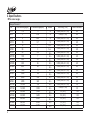
2. Specifications
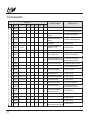
◆Pressure ranges
Gauge Pressure (1)
P/N
V15
GP2
GP5
GP10
GP15
GP30
GP50
GP100
GP300
GP500
GP600
GP1K
GP2K
GP3K
GP5K
GP10K
GP15K
GP20K
GP25K
GP30K
GP36K
GP40K
2
Pressure Range(psi)
-15
2
5
10
15
30
50
100
300
500
600
1,000
2,000
3,000
5,000
10,000
15,000
20,000
25,000
30,000
36,000
40,000
Pressure Range(bar)
-1
0.16
0.35
0.7
1
2
3.5
7
20
35
40
70
140
200
350
700
1,000
1,400
1,600
2,000
2,500
2,800
Media
G
G
G
G
(2)
G, L
G, L
(2)
G, L
G, L
G, L
G, L
G, L
G, L
G, L
G, L
G, L
G, L
G, L
G, L
G, L
G, L
G, L
G, L
Accuracy(%FS)
0.025 (0.05, 0.1, 0.2)
0.05 (0.1, 0.2)
0.025 (0.05, 0.1, 0.2)
0.025 (0.05, 0.1, 0.2)
0.025 (0.05, 0.1, 0.2)
0.025 (0.05, 0.1, 0.2)
0.025 (0.05, 0.1, 0.2)
0.025 (0.05, 0.1, 0.2)
0.025 (0.05, 0.1, 0.2)
0.025 (0.05, 0.1, 0.2)
0.025 (0.05, 0.1, 0.2)
0.025 (0.05, 0.1, 0.2)
0.025 (0.05, 0.1, 0.2)
0.025 (0.05, 0.1, 0.2)
0.025 (0.05, 0.1, 0.2)
0.025 (0.05, 0.1, 0.2)
0.05 (0.1, 0.2)
0.1 (0.2)
0.1 (0.2)
0.1 (0.2)
0.1 (0.2)
0.1 (0.2)
Burst Pressure
3X
3X
3X
3X
3X
3X
3X
3X
3X
3X
3X
3X
3X
3X
3X
2X
2X
1.5X
1.5X
1.5X
1.5X
1.1X
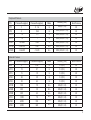
Compound Pressure
Accuracy(%FS)
Burst Pressure
G
0.05 (0.1, 0.2)
3X
G
0.025 (0.05, 0.1, 0.2)
3X
G
0.025 (0.05, 0.1, 0.2)
3X
3X
P/N
Pressure Range(psi)
Pressure Range(bar)
Media
CP2
2
0 .16
CP5
5
0.35
0.7
CP10
1 0
CP15
1 5
CP30
-15 to 30
-1 to 2
G
G
0.025 (0.05, 0.1, 0.2)
0.025 (0.05, 0.1, 0.2)
3X
CP100
-15 to 100
-1 to 7
G, L
0.025 (0.05, 0.1, 0.2)
3X
CP300
-15 to 300
-1 to 20
G, L
0.025 (0.05, 0.1, 0.2)
3X
Pressure Range(bar)
Media
Accuracy(%FS)
Burst Pressure
3X
1
Absolute Pressure
P/N
Pressure Range(psi)
5
0.35
G
0.1 (0.2)
A P 10
10
0.7
G
0.1 (0.2)
3X
AP 15
15
1.0
G
0.1 (0.2)
3X
AP 30
30
2.0
0.1 (0.2)
3X
AP5
50
3.5
G
G
0.1 (0.2)
3X
AP 100
100
7.0
G, L
0.05 (0.1, 0.2)
3X
AP 300
300
20
G, L
0.05 (0.1, 0.2)
3X
0.05 (0.1, 0.2)
3X
AP 50
AP 500
500
35
G, L
A P1K
1,000
70
G, L
0.05 (0.1, 0.2)
3X
A P3K
3,000
200
G, L
0.05 (0.1, 0.2)
3X
A P5K
5,000
350
G, L
0.05 (0.1, 0.2)
3X
3
Differential pressure
P/N
Pressure Range(inH 2 O)
Pressure Range(mbar)
Media
DP1
1
2 .5
G
DP2
2
5 .0
G
5
Accuracy(%FS)
Burst Pressure
0.05
(3)
100X
0.05
(3)
100X
1 0
G
0.05
50X
DP10
1 0
2 5
G
0.05
20X
DP20
2 0
5 0
G
0.05
20X
DP30
3 0
7 5
G
0.05
20X
DP50
5 0
1 60
G
0.05
3X
DP150
1 50
3 50
G
0.025 (0.05)
3X
DP300
3 00
7 00
G
0.025 (0.05)
3X
DP5
R emark: G=Gas, L=Liquid, V=high pressure vapor
Note: (1) Sealed gauge pressure for above 1,000 psi
(2) 0.025% FS for gas media only
(3)* One year accuracy (including yearly stability) except DP1 and DP2 range which is 0.05%FS calibration
accuracy and 0.05%FS yearly stability.
Negative pressure: (lower limit of measurement ~ 0), numeric area of lower limit of measurement: -1bar ~ 0bar .
Compound pressure: (lower limit of measurement ~upper limit of measurement), numeric area of lower limit of
measurement: -1bar ~ 0bar. Numeric area of upper limit of measurement is: 0~6 bar...2,500bar.
◆ Instrument types: Standard and intrinsically safe.
2
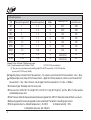
◆ Pressure units: mmH 2 O@ 4 ° C, mmHg @ 0 ° C, inH 2 O @ 4 ° C , inHg @ 0 ° C,kgf/cm , psi, kPa, MPa, Pa, mbar and bar,
customized pressure units.
◆ Over Pressure: when the measured value of pressure is greater than 120% FS, the entire screen will flash as an alarm.
◆ Measuring speed: the measuring speed can be customized. The default is 3 readings per second.
◆ W orking environment: a. Ambient temperature: (-10~50)℃.
b. Relative humidity: <95%.
c. Atmospheric pressure: (86~106)kPa.
4
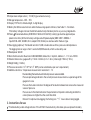
◆Temperature compensation: ( - 10~50)℃ (guaranteed accuracy).
◆ Storage temperature: -20℃~70℃.
◆ Display: FSTN LCD, white backlight, 5-digit display.
◆ Battery life: 600 consecutive hours when the measuring speed is 3 times/s, See Table 11-1 for details.
If the battery voltage is too low, the 681will automatically shut down prior to any accuracy degradation.
◆ Power: 9V alkaline batteries (ANSI/NEDA 1604A or IEC 6LR61), battery type must be approved (see
power instructions) for the intrinsically s afe type and a 9V power adapter (GME G051T-090065-1
Input AC100-240V, 50/60Hz, 0.2A, output DC9V, 0.65A) can also be used for the basic type.
◆ Data logging (optional): The totaled record is 21,800, includes date and time, pressure and temperature.
The logging interval range is from 1 second to 99,999 seconds, which can be set by user.
◆ Rated power: 60mW.
◆ Serial Communication: Baud rate: 2400/4800/9600, 8 data bits, 2 stop bits, Address: 1 ~ 112, Um=10VDC.
◆ Exterior dimensions: gauge outfit φ112mm Χ 35mm (4.41 x 1.38 in), total length 178mm (7.01 in).
◆ Weight: 580g (1.28 lbs).
◆ Pressure connection: 1/4”NPT or 1/4”BSP (can be customized as per user's requirement).
◆ Additional functions: Temperature measurement: resolution 0 .1℃.
Peak recording: the maximum and minimum pressure values recorded.
Pressure percentage indication: the current pressure measurement as a percentage of the
gauges full scale.
Pressure fluctuation indication: the degree of fluctuation between two consecutive measured
values of pressure.
Pressure alarm threshold indication: the permutation of 3 pointers indicating whether the
current pressure is higher than the alarm threshold.
Remark: For optional data logging, the flashing icon “%” means data is being logged.
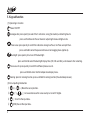
3. Instructions for use
Provides battery under voltage indicator. If the ADT681IS automatically shuts down, please replace the battery .
5
Do not replace the battery in an area with hazardous explosives.
Only use batteries that have passed Ex approval tests. The use of any other batteries will invalidate the Ex approval
and may result in safety risks.
Never open the instrument case, otherwise the Ex approval will be invalidated.
It is strictly prohibited to connect RS232 communication cables in areas with explosives, Um=10VDC.
Do not replace the components or casing, as such replacements may weaken the explosion-proof performance.
When used in hazardous locations, the instrument case should be prevented from being impacted or falling.
Do not position the equipment so that it is difficult to operate the disconnecting device.
It is strictly prohibited to paste any non-metal labels larger than 400mm 2 on the instrument's casing.
Plug of the external power adaptor is used as disconnect device.
Please use wet cloth (with water) periodic cleaning and maintenance on the instrument.
If the instrument is not used for a long time, please remove the battery to save the battery life.
The equipment may not be covered under warranty if used in manner not specified by the manufacturer.
Prohibited for a long time outdoor use to avoid water or rain.
Avoid using the instrument over-pressure on a long-term basis to avoid damaging the pressure sensor.
Protective boot is not ATEX certified and should not be used in hazardous areas.
CSA MARKINGS:
Reference to a specific installation document to indicate special conditions for safe use preventing installation in
an area subject to mechanical impact.
“WARNING: SUBSTITUTION OF COMPONENTS MY IMPAIR INTRINSIC SAFETY” and“AVERTISSEMENT:
LA SUBSTITUTION DE COMPOSANTS PEUT COMPROMETTRE LA S É CURIT É INTRINS È QUE”
“WARNING: DO NOT CONNECT OR DISCONNECT THE RS232 COMMUNICATION CABLE IN A HAZARDOUS
ATMOSPHERE” and “AVERTISSEMENT: NE PAS BRANCHER OU D É BRANCHER LE C Â BLE DE
COMMUNICATION RS232 DANS UNE ATMOSPH È RE DANGEREUSE”
“WARNING: TO PREVENT IGNITION OF A HAZARDOUS ATMOSPHERE, BATTERIES MUST ONLY BE CHANGED
IN AN AREA KNOWN TO BE NONHAZARDOUS” and “AVERTISSEMENT: AFIN DE PR É VENIR
6
L'INFLAMMATION D'ATMOSPH È RES DANGEREUSES, NE CHANGER LES BATTERIES QUE DANS DES
EMPLACEMENTS D É SIGN É S NON DANGEREUX.”
“WARNING: USE ONLY TYPE GP 1604A, or PANASONIC 6LR61, 9 V BATTERIES” and
“AVERTISSEMENT – UTILISER UNIQUEMENT DES ACCUMULATEURS GP 1604A, or PANASONIC 6LR61, 9 V”
N.B: the mark“ ”is only for ADT681 (intrinsically safe version).
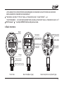
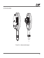
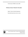
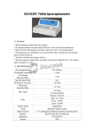
4. Basic structure
Model
RS232 Serial Port
Nameplate
RS232 Serial Port
Screen
Name-plate
Electricity Jack
Fitting Bolt
Buttons
256358
Fitting Bolt
Range : (-100~100)kPa
Accuracy : 0.02%FS
S / N : 211 H 11440005
Range
( 0~1 0 0 ) k P a
Sensor Cavity
Male Thread Coupling
Front View
Back View(Basic type)
Back View(Intrinsically Safe Type)
7
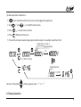
5. Keypad function
(1) Operating instruction
Power ON/OFF
Analogue dial : press quickly to select the % indication, swing (fluctuation) and low/high alarm.
press and hold to enter the set menu for adjusting the low and high alarms.
Peak value : press quickly to switch the indication among max Peak, min Peak and quit Peak.
press and hold to enter the password menu or data logging menu (optional).
Backlight: press quickly to turn on / off the backlight .
press and hold to select the backlight display time ( ON , 20s and 30s), and release it after selecting .
Pressure units: press quickly to switch the different pressure units .
press and hold to enter into the temperature display menu .
Zeroing: press for zeroing function, press and hold for zeroing function ( t he absolute pressure).
(2) Data inputting introduction
①
(←),
②
8
(↑),
(→) Move the cursor position .
(↓) Increase/decrease the value nearby cursor with 1 digital .
)Confirm the input data .
③
(
④
(ESC)Cancel the input data.
(3) Menu operation introductions
①
② Use
press and hold to enter the set menu or data logging menu(optional).
(↑)and
(↓) to switch the menu items .
): to select menu function .
③ Press
(
④ Press
(ESC) to exit the menu .
⑤ The coefficient input includes integral part and decimal part, for example: input the 4.0146
Adjust sign ('+' and '-')
Adjust intergal
“+ 4”
+1 ( 00001 +. 0000 )
Adjust decimal
“0 . 0146”
Remark: If the symbol
is flashing, please input “+” or “-”
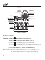
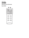
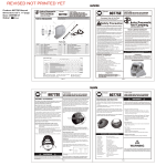
6. Display function
9
Analogue dial
% indication
Pressure swing
Battery icon
Scale midpoint
Scale bar graph
Sector pointer area
Pressure units area
Overpressure alarm
Temperature unit
Calibration icon
Higher limit
Data display area
Lower limit
Pressure peak
Picture 6-1: Screen area
The ADT681 screen definitions .
◆Battery icon: the battery icon
indicates the battery voltage is higher than 7.8V.
The battery icon
indicates the battery voltage is between 7.8V and 7.3V .
T he battery icon
i ndicates the battery voltage is between 7.3V and 6.7V .
T he battery icon
indicates the battery voltage is below 6.7V. T he battery should be replaced.
I f the battery voltage is lower than 6.5V, the ADT681 will power off automatically.
◆Pressure unit area: Pressure unit area: Eleven common pressure units, and one customized pressure units
(The ADT681 has 5 digit resolution based on the unit type selected at time of order) .
10
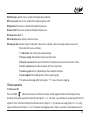
◆Calibration icon: the mark or symbol of the operating calibration.
◆Pressure peak: the mark or symbol of the displaying peak value.
◆Higher limit: the mark or symbol of the high limit pressure.
◆Lower limit: the mark or symbol of the lower limit pressure.
◆Temperature unit: ℃.
◆Data display area: display s all data or menu.
◆Analogue dial: includes 3 types of indications: pressure % indication, pressure swing, overpressure alarm.
The content of the area as follows:
① % indication: the current pressure percentage.
② Pressure swing: the indication of pressure fluctuation.
③ Overpressure alarm: the alarm indication for overpressure (can be set of max/min limits).
④ Sector pointer area: includes resolution of 51 bars or pointers.
⑤ Scale bar graph: will vary depending on the analog dial selection.
⑥ Scale midpoint: the middle position of the scale bar graph.
⑦ For optional data logging the flashing icon “%”means the data is logging.
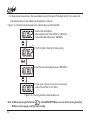
7.Basic ope ration
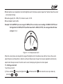
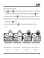
7.1 Power on/off
Press and Hold
about 3s to power on or off the instrument. All the segment of the LCD will display initially
illuminate at the power up of the instrument (see Figure 7-1-1). The users can see if there is any damage of the LCD's
segment. Then, the LCD will display the software version (Figure 7-1-2) and pressure range (Figure 7-1-4). Lastly,
it goes to home screen (Figure 7-1-5). For optional data logging version, there is one more screen between version
11
screen and pressure range screen (figure 7-1-3).
Figure 7-1-1: Power up screen
Figure 7-1-2: Version screen
Figure 7-1-4: Upper range screen
7.2 Pressure measure
When in any menu, pressing
B attery icon
Figure 7-1-3: data logging screen(optional)
Figure 7-1-5: Home Screen
returns to the home screen (Figure 7-3).The home screen content includes:
P ressure measure value
P ressure units
A nalogue dial indication
Note: initially, these register values are set to the factory calibration values. If the pressure exceed 120%FS,
12
the whole screen will flash to alert the user.To prevent damage to the sensor, release the pressured
immediately. When the alarm goes off, the measure speed of the ADT681 automatically changes to10
times per sec in order to catch up the pressure change. When the alarm stops,the speed will go back
to normal.
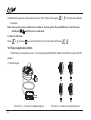
7.3 Zeroing
(1) Gauge sensor types:
To zero the ADT681 press the
key. Before zeroing the ADT681, the current pressure should be in the range
of -2% ~ 2% FS. Figure 7-3-1 shows the zeroing sequence of gauge pressure.
Figure 7-3-1: t he zeroing pro c ess of the ADT681
(2) Absolute sensor types:
① When the ADT681 is connected to atmosphere, the user should know the current atmosphere pressure value
(Pstandard).
② The actual pressure of ADT681 is (Pmeasure).
③ Press and hold
to enter the data input state, then input the actual pressure (Pstandard).
13
④ In the pressure measure menu, the measured pressure will change to (Pstandard) which is the same as the
atmosphere pressure value. Now the zeroing process is finished.
Figure 7-3-2 shows the zeroing sequence for absolute pressure of the ADT681.
1.Contact with atmosphere.
Measured pressure of the ADT681 is 100.02kPa .
Actual atmosphere pressure is 100.00kPa.
2.The f ir st digit will flashing for data inputting .
input
3.Input the actual atmosphere value of 100.00kPa.
4.In the menu of pressure measure, the measured
value of the ADT681 is 100.00kPa.
Figure 7-3-2: Zeroing process of absolute pressure
Note: A. When selecting the third item
in the MENU OPTION you can cancel the zeroing operation.
B. Make sure the gauge is upright while zeroing.
14
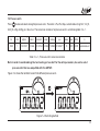
7.4 Pressure units
2
to view and select among the pressure units. The order is Pa , kPa , Mpa, customized unit, kgf/cm , inH 2O ,
Press
mmH 2O , inHg , mmHg , psi , mbar , bar. The conversion relation of all pressure units is as following table 7-4-1.
2
Pa
kPa
kgf/cm
1000
1
0.010197
inH 2O
mmH 2O
4.01463 101.97162
inHg
mmHg
psi
mbar
bar
MPa
0.2953
7.50062
0.1450377
10
0.01
0.001 customized unit
C
Table 7-4-1:Pressure units' conversion relation
Note: in order to avoid readings that are too long or too short for the units parameters, be sure to select
pressure units that are compatible with the ADT681 .
Figure 7-4 shows the methods to switch the different pressure units.
Figure 7-4: Switching method
15
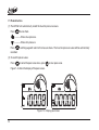
7.5 Peak detection
(1) The ADT681 will automatically record the max/min pressure values.
Press
to view them.
-------Shows max pressure.
------- Shows min pressure.
Press
and the gauge will return to the measure menu. The max/min pressure values will be automatically
recorded.
(2) To reset the peak values .
Press
to enter the peak value menu , press
to clear peak value .
Figure 7-5 shows the display of the peak value s .
Figure 7-5: Display peak value
16
7.6 Backlight
Press
to power on/off the backlight. The selectable times are ON, 20 seconds and 30 seconds.
The selection method is as follows:
(1) Press
and hold to display and select among the following options.
Figure 7-6: Backlight auto power off options
(2) Press
and hold to select auto power off time setting (ON, 20, 30), then release when the desired option appears .
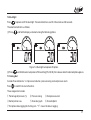
7.7 Analog dial
Includes three indications: % of pressure indication, p ressure swing and overpressure alarm.
Press
to switch from one to the other.
The analogue dial includes:
① Percentage of pressure (%)
② Pressure swing
③ Overpressure alarm
④ Sector pointer area
⑤ Scale bar graph
⑥ Scale midpoint
⑦ For optional data logging the flashing icon “%”means the data is logging.
17
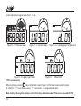
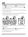
7.7.1 Percent pressure
◆% indicator: shows the current pressure percentage .
◆Sector pointer area: shows the pressure ranges and the trend of pressure
changes in a fan- shape d pattern.
Note: t he differential pressure, gauge pressure, absolute pressure,
Compound pressure types have different display s .
◆Scale bar graph: 0%~100%, the minimum scale is 2% .
◆Scale midpoint: point to 50%.
Figure 7-7-1: Pressure % indication
Example: for the ADT681 with (0~100) kPa, if the current pressure
value is 50kPa, the % indicator is 50%, as figure 7-7-1.
7.7.2 Pressure swing
◆Pressure swing icon: indicates the pressure fluctuation.
◆Sector pointer area: uses one pointer to show the fluctuation degree of
two adjacent separate pressure values.
◆Scale bar graph: range is (-0.25%~0.25%) FS, the min scale is 0.01%FS.
◆Scale midpoint: point to 0.00%FS position
Example: for the ADT681 with (0~100) kPa, if the current pressure
Figure7-7-2:Pressure swing indication
reading is 50.01kPa and the previous pressure was 50.11kPa,
the fluctuation degree for 2 seperate pressures is - 0.1%FS, as figure 7-7-2 shows.
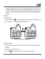
7.7.3 Overpressure alarm
◆Overpressure alarm icon: indicates an overpressure condition.
18
◆Sector pointer area: two pointers to show the high/low alarm limit pressure percentage, the 3 rd pointer show s the current
pressure percentage .
◆Scale bar graph: (0%~100%) FS, minimum scale is 2%FS .
◆Scale midpoint: point to 50%.
Example: for the ADT681 (pressure range 0-100kPa) ,if the current pressure reading is 50.00kPa (50%FS) and
the higher limit is 80kPa (80%FS) and the lower limit is 40kPa (40%FS), the analogue dial will show
as figur e 7-7-3.
Figure 7-7-3: Overpressure Alarm
When the current pressure is beyond the range of the hi g h /low limit, the whole screen will flash to warn the user to
adjust the pressure. Meanwhile , In order to catch up to the pressure change, the measure speed will automatically
adjust to ten times per second . Once the alarm is over, the display will go back to normal speed.
7.7.4 Setting alarm limit
To set the alarm limit:
(1) Press and hold
pressing
display the higher limit
or
and the lower limit
then move the cursor up or down by
.
19
(2) Press
or
be set, when
to access the alarm adjust status, then when
is displayed, the higher pressure limit can
is displayed, the lower pressure limit can be set. After these steps are completed, press
to select negative (-) or positive (+) values.
(3) After the high limit is adjusted, the menu will automatically enter the lower limit and then return to the normal screen.
The sequence is: High limit , Low limit , Quit.
(4) The ADT681 automatically checks the validity of the input data. If there is a problem or if the data input is not valid,
the ADT681 will not accept the change. Figure 7-7-4 shows the setting menu.
Figure 7-7-4: The setting menu of the high or limit and the lower limit
Figure 7-8: Temperature measure menu
7.8 Temperature measure
Press
and hold to enter the temperature measure menu, press
again to go back to the pressure measure
menu. The temperature measure range is -30℃~90℃, the minimum resolution is
Figure 7-8 shows the temperature measure menu.
20
0.1℃.
7.9 Data logging (optional)
7.9.1 Save menu
Press and hold the
button to enter into the data logging menu. The screen shows
(data logging) and
(set menu), please select the
(1)
: 1. Display the date and time. 2. Set up the date and time.
(2)
: Memory capacity status.
(3)
.
: Upload data.
(4)
: Delete all data, the password is “211".
(5)
: Logging interval (00001s-99999s).
(6)
: “on”means to start data logging, and “off”means to stop the data logging.
Remark: when capacity is full, please delete all data for logging new data.
7.9.2 To log data
(1) Set up the date and time
(2) Set up the logging interval
(3) Start to log
Examples: Automatic storage, the interval is 1 second:
① Set up the actual date and time(No.
② Select the gap menu option (No.
③ Change the logging status to "on" (No.
)
) and set up the logging interval as 00001S.
)
④ Return to main menu. The % icon should be flashing to indicated data logging is active.
⑤ Except for the
button, all other buttons are locked.
21
⑥ The data can be sent by Additel/Land software.
Remark: While the Additel 681 is sending data, it will stop logging.
⑦ Press “del” in the data logging menu to delete all data, the password is 211.
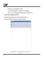
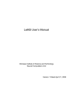
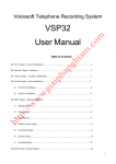
7.9.3 Export data via Additel/Land software.
(available for free download at http://www.additel.com/products/Software/)
(1) Connect the Additel 681 with computer, run Additel/ Land software.
7-9-3-1
22
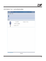
(2) Click the button “ Scan”, you will see the picture below.
7-9-3-2
23
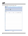
(3) After clicking the Additel 681, the next window will appear as below.
7-9-3-3
24
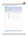
(4) Click the “Refresh” button to send data from Additel 681 to software.
7-9-3-4
25
(5) Click the “Export” button to send the data with EXCEL format.
Flashing,input password
Figure 8-1-1: Enter the password menu
7-9-3-5
( 6 ) Press the “delete” button to delete all data
8. Menu operation
8.1 Enter the Menu
(1) Press and hold the
button enter into the set menu (password), as shown in Figure 8-1-1.
(2) Input password“211”.
Remark: For Additel 681 with data logging, Press and hold the
The screen shows
button to enter into the data logging menu.
(data logging, see more details in 7.9) and
Note: if the password is wrong, the menu will return to the previous menu.
26
(set menu)
8.2 Menu option
There are 12 options, as shown in Figure 8-2-1.
Figure 8-2-1: 12 menu options
Details as below:
(1)
To enter into the calibration menu .
(2)
The ADT681 ha s been calibrated already .
The ADT681 ha s n't been calibrated yet .
If this step is used , all pressure calibration will be cancelled. Be careful when us ing this operation .
(3)
canc els the previous zeroing operation .
(4)
set s measure speed .
(5)
sets filtering effectively .
(6)
sets the address of RS232.
(7)
sets the baud rate of Rs232.
(8)
set automatic shutdown timer time.
(9)
sets 4 or 5 digit display .
(10)
set custom unit factor.
27
(11)
set tare function.
(12)
set single-point calibration.
8.3 Enter/cancel the calibration
enters the calibration.
canels the calibration.
8.4 To cancel the previous zeroing
cancels the previous zeroing operation.
8.5 To set measure speed
Select
to enter the selection menu of the measure speed as follows:
CON(10 times/1 sec)
13 (3 times/1 sec)
12 (2 times/1 sec)
11 (1 times/1 sec)
21 (1 times/2 sec)
31 (1 times/3 sec)
41 (1 times/4 sec)
51 (1 times/5 sec)
61 (1 times/6 sec)
71 (1 times/7 sec)
81 (1 times/8 sec)
91 (1 times/9 sec)
101 (1 times/10 sec)
The factory default is 1-3 (3 times/1 sec).
8.6 To set filtering effectively
Select
for "filtering is valid" ,
for "filtering is invalid" .
8.7 Set RS232 address
Select
to set the RS232 address from the range 1 to 112. The factory default is 1.
8.8 To set the RS232 baud rate
Select
28
to set the RS232 baud rate from the options of 2400 and 4800 and 9600.The factory default is 9600.
8.9 To set the automatic shutdown
Select
, sets the automatic shutdown function. (1/5/10/15/30/45/60/90/120 minutes and off function can
be set)
8.10 To set the 4 or 5 digit display
Select
to change the 4 or 5 digit display.
8.11 Set custom unit factor
Select
, sets the coefficient of customized pressure units. In the other words, user can customize a
pressure unit by setting a conversion ratio based on pressure unit “kPa”. This ratio's range is from 0.0001 to 99999,
but only shows 5 digits.
For example: The coefficient is 1000 as coefficient, the display pressure value is equal with the pressure with unit
“Pa”. The symbol of customized pressure unit is “C”. The conversion format: 1kPa = coefficient x C.
8.12 Set tare function
Select
, sets a pressure as new reference zero (the pressure unit should be kept the same as main menu).
8.13 Set single-point calibration
Select
, sets single point calibration.
(1) Pressure zeroing
(2) Set one non-zero pressure point, records the display pressure readings.
(3) Calculate the adjustment ratio accordingly and set it in the Additel 681.
Example: Set 1.65kPa standard pressure, but the display pressure reading is 1.5kPa. In order to correct the display
29
pressure readings, you should make an adjustment ratio q=1.65/1.5=1.1. After input the ratio 1.1, all readings will be
multiplied 1.1. Therefore, if you set 1.65KPa again, the display reading is 1.650 (1.500 x 1.1 =1.650)
Remark: the adjustment ratio range is 0.0001 ~ 9.9999
9.Calibration function
It is recommended that the ADT681 be calibrated once per year by a trained professional. For best results before
calibration , the ADT681 should be exercised to full scale three times . If there is an error during the process then use
the cancellation function .
Note: all calibration must take place in stable ambient laboratory conditions.
9.1 Calibration conditions
(1) Environment: temperature: 20℃
2℃, relative humidity: (45-75) %, atmosphere pressure: (86~106) kPa.
(2) Standard pressure source. Example: Dead weight tester or Additel 9XX series pressure pumps.
(3) High precision reference standard.
9.2 Calibration process
Select Menu to enter the calibration menu. There are two different pressure gauges:
(1) Single scale gauge: to calibrate, first set the "low", then pressurize to set the "high".
(2) Dual scale gauge: first set the lower limit, then zero, then set the higher limit.
The calibration point can be modified if it meets the following conditions:
(1) The pressure value of the 1 st point is lower than the 2 nd point.
(2) The pressure value of the 2 nd point value is lower than the 3 rd point.
30
Example: the ADT681 with (0~100) kPa.
(1) Select
and press
to display the calibration value of lower limit, as the figure 9-2-1. If the use r needs
to modify the pressure value of the low limit point then input the desired value. Otherwise, press
(2) To calibrate the lower limit point: press
to confirm.
to confirm till the actual pressure value is stable. As in Figure 9-2-2.
(3) Display higher limit point: as in Figure 9-2-3, input the desired data if the user needs to modify the calibration
value. Otherwise, press
to confirm.
(4) To calibrate the higher limit point: p ress
un til the actual pressure value is stable. As in Figure
9-2-4.
Flashing,input new calibration point
lower limit point display menu
Picture 9-2-1
The actual pressure measurement value
lower limit calibration menu
Picture 9-2-2
Flashing,input new calibration point
higher limit point display menu
Picture 9-2-3
The actual pressure measurement value
higher limit calibration menu
Picture 9-2-4
31
nd
(5) When the screen returns to the calibration menu, the 2 option will change to
.This shows the calibration
is complete.
Note: three-point pressure calibration is similar to the two-point. The only difference is that the icons
will display
while the zero is calibrated.
9.3 Cancel calibration
Select
and push
to cancel the calibration, then the screen will display
.
10. Power supply description
The ADT681 has two power sources: a 9V alkaline battery(ANSI/NEDA 1604A or IEC 6LR61) or special DC9V
adapter.
(1) Standard type:
Picture 10-1-1:Connect the adapter diagram
32
(1)
(2)
(3)
(4)
Picture 10-1-2:Battery installation diagram
(2) Intrinsically safe type:
(1)
(2)
Picture 10-2-1:Battery installation diagram
33
W arning:
◆Replace the battery if the ADT681 powers off automatically.
Remove the ADT681 from the Ex-hazardous area before opening the battery door.
Use only the battery types listed in the Approved Battery Table.
◆When replacing the battery, make sure positive and negative are in the right direction.
Approved Batteries:
Battery
Manufacturer
Type
Alkaline, 9 volt
Panasonic
6LR61 9V
Alkaline, 9 volt
1604A 9V
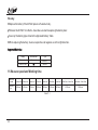
11. Measure speed and Working time
Measure
speed
Battery
life
10times/1sec 3times/1sec
300hours
600hours
2times/1sec
1time/1sec
1time/2sec
1time/3sec
1time/4sec
1time/5sec~1time/7sec
1time/8sec~1time/10sec
800hours
1500hours
2000hours
2500hours
3000hours
4000hours
5000hours
Table11-1
34
12. Accessories
(1) Warranty
1pc
(2) User's Manual
1pc
(3) Adapter G051T-090065-1
1pc (optional)
(4) Pressure test report
1pc
(5) Traceable certificate of calibration
1pc (optional)
13.Contact us
The product specifications and other information contained this manual are subject to change without notice.
Additel Corporation has made a concerted effort to provide complete and current information for the proper use
of the equipment.
If there are questions, contact Additel Corporation:
Additel Corporation
22865 Savi Ranch Parkway Ste F
Yorba Linda, CA 92887, USA
Phone: 714-998-6899
Email: [email protected]
website: www.additel.com
35
Appendix I: Communication protocols
1. Instructions format
1.1 PC machine's send format
A:X:Knnnn: C0:C1:C2:C3:C4+ Eos (End of symbol)
A:1 byte, the communication address of ADT681
X:1 byte, only for W (write) or R (read)
K:1 byte, M (for measure operation), F (for file operation), O (other operation)
nnnn:2-5 bytes, the item operated by K instruction
C0:C1:C2:C3:C4: Parameter, refer the specified instruction introduction
Eos: 0x0(Hex)
1.2 Return format of the ADT681
A:X:Knnnn:C0:C1:C2:C3:C4+Eos,hereinto:
A:Communication address of the ADT681
X:E or F,
E: error information of this frame data.
F: feedback information.
Knnnn:It is same as the instructions from upper machine
C0,C1,C2,C3,C4:Feedback data or error information or ok
Eos:0x0(Hex)
1.3 Error information code instruction
1000: Receive the overflow from buffer zone.
1001: The user cannot perform this task
1004: Irregular code has been entered
1005: The pressure unit is unavailable
36
1007: The parameter settings are irregular
1016: The current data is not the range of zeroing
1017: The number of parameters entered does not meet the parameter settings
1018: This instruction is non-existent
1019: The length of the operation code is too long
1020: The r/w of instruction is wrong
1024: The setting of pressure unit is irregular
1025: The serial port's address code is too long
1026: The baud rate is wrong
1029: Some parameter codes are too long
1.4 The series port's communication collocation
Communication
Address
Baud rate
Data length
Stop bit
Parity bit
Flow control
1~112
2400
4800
9600
8
2
N/A
N/A
The protocol supports two types of address format as following:
1. 1-byte address, the address is a hexadecimal. Example:
[0x01]: R: MRMD: [terminator], the terminator is 0x0x0, 0x0a or 0x0d;
2. 3-byte address, the address is a string. Example:
[001]: R: MRMD: [terminator], the terminator is 0x00, 0x0a or 0x0d;
[255]: R: MRMD: [terminator], '255' is a universal address. It will be work whatever the calibrator's address is.
37
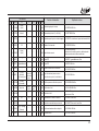
2. Instructions details
Instructions
A
38
Function Introduction
Right return value
C1
-
C2
-
C3
-
C4
-
Eos
0x0
Read the software version number
A: F: OVER: version No.+Eos
R
OVER
C0
-
R
OTYPE
-
-
-
-
-
0x0
Read the instrument model number
A: F: OTYPE: instrument model No.+Eos
R
OCODE
-
-
-
-
-
0x0
Read the serial number of the
instrument
A: F: OCODE: serial number+Eos
A: F: OPRDA: manufacture date+Eos
X
Knnnn
R
OPRDA
-
-
-
-
-
0x0
Read the manufacture date of the
instrument
W
OBLAC
0(close)1(open)
-
-
-
-
0x0
On/off backlight
A : F : OBLAC : OK+Eos
W
OBLAT
0/20/30
-
-
-
-
0x0
Set the time of backlight turn off
Option : ON、20s、30s
A : F : OBLAT : OK+Eos
W
OKEY
0(close)1(open)
-
-
-
-
0x0
On/off keypad
A : F : OKEY : OK+Eos
R
OBATV
-
-
-
-
-
0x0
Read the voltage of battery
A : F : OBATV : battary voltage+Eos
R
ORAN
-
-
-
-
-
0x0
Read instrument's pressure range
A: F: ORAN: l ower limit: upper limit:
Pressure type:0(gauge) 1(absolute) pressure unit: pressure type+Eos
R
MRMD
-
-
-
-
-
0x0
Read the actual pressure value
A : F : MRMD : pressure value: unit+Eos
R
OTEMP
-
-
-
-
-
0x0
Read the environment temperature
A : F : OTEMP : temperature : ℃+Eos
W
MZERO
-
-
-
-
-
0x0
Cancel the zeroing pressure
A : F : MZERO : OK+Eos
W
OZERO
-
-
-
-
-
0x0
Zero the pressure value
A : F : OZERO : OK+Eos
W
OCONT
0(close)1(open)
-
-
-
-
0x0
Set the sending data continuously
A : F : OCONT : OK+Eos
W
OUNIT
Unit shortening
-
-
-
-
0x0
Switch the pressure units
A : F : OUNIT : OK+Eos
R
OUINF
-
-
-
-
-
0x0
Read the code of optional units
A : F : OUINF : unit info code +Eos
-
-
-
-
0x0
Read pressure peak value
A : F : OPEAK : max peak value :
min pear value : pressure unit +Eos
R
OPEAK
-
W
OPKZE
-
-
-
-
-
0x0
Zero pressure peak value to actual
measured pressure value
A : F : OPKZE : OK+Eos
R
OADDR
-
-
-
-
-
0x0
Read series port address(1-112)
A : F : OADDR : address +Eos
W
OADDR
Address
-
-
-
-
0x0
Set up the series port address
A : F : OADDR : OK+Eos
W
OBAUD
Baud rate
-
-
-
-
0x0
Set the baud rate (2400,4800,9600) A : F : OBAUD : OK+Eos
W
OFALT
-
-
-
-
-
0x0
Cancel the pressure parameter to
operation, go back to factory default A : F : OFALT : OK+Eos
Instructions
A
X
Knnnn
Function Introduction
Right return value
C1
C2
W O F RUN
0(stop)
1(start)
-
-
-
-
0x0
Set data logging start or stop
A:F: OFRUN:OK+Eos
W
O F TIM
interval
-
-
-
-
0x0
Set recording interval (1s~99999s)
A:F: OFTIM:OK+Eos
R
OFSTA
-
-
-
-
-
0x0
Read the operating status of data logging
A:F: OFSTA:state:interval:space:total records+Eos
W
OFDEL
211
-
-
-
-
0x0
Delete all data records
A:F: OFDEL:OK+Eos
W
OFSAP
0(stop)
1(start)
-
-
-
-
0x0
Send all data records
A:F: OFSAP:OK+Eos
Automatically send data packets, detailed packet
format, please contact the manufacturer
R
ORTC
-
-
-
-
-
0x0
Read RTC
A:F:ORTC: yymmddhhmmss +Eos
-
-
-
0x0
Write RTC
A:F:ORTC:OK+Eos
-
-
-
0x0
Entrance instruction of calibration
A : F : OCPS : OK+Eos
-
-
-
0x0
Input the standard pressure value
and calibration points, for calibration
A : F : OCP : OK+Eos
A : F : OCPOK : OK+Eos
W
ORTC
yymmddhhmmss
-
W
OCPS
-
-
W
OCP
1(save)
0 (unsaved)
-
-
-
-
0x0
Quit the pressure calibration process
ALARM
High limit
lower
limit
Pressure
unit
-
-
0x0
Set the alarm limit
A : F : ALARM : OK+Eos
ALARM
-
-
-
-
-
0x0
Read alarm limit
A : F : ALARM : high limit : lower limit :
pressure unit +Eos
-
-
W OCPOK
W
R
Standard
Z (zero)
pressure of
M(middle)
calibration
F (full scale point)
point
C3 C4
Eos
C0
D0
D1
-
0x0
Set measure D1 times/ D0 second
A : F : MRATE : OK+Eos
MRATE
-
-
-
-
-
0x0
Read the measured times per second
A : F : MRATE : seconds: times+Eos
W
ODIAL
0(%) 1(swing)
2( a larm)
-
-
-
-
0x0
Set the work mode on the analog dial
A : F : ODIAL : OK+Eos
W
ORPP
-
-
-
-
-
0x0
Software Reset
A : F : ORPP : OK+Eos
W MRATE
R
39
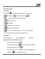
3.Pressure units abbreviations
Shortening
KGF
INH 2 O
H2O
INHG
HG
PSI
MBAR
BAR
PA
KPA
MPA
C
Standard
kgf/cm 2
inH 2O
mmH 2O
inHg
mmHg
psi
mbar
bar
Pa
kPa
MPa
customized units
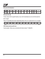
4.Pressure units code
The data read by OUINF are algorithms(binary scale), check the selected pressure units after the hexadecimal
date is changed.
2 bytes. The selectable pressure code is represented by 2 bytes. 1(this unit is available), 0(This unit is unavailable).
kgf/cm 2
inH 2O
mmH 2O
inHg
mmHg
psi
mbar
bar
Pa
kPa
MSB-10
5.Data automatically transmit format
Total data length is 16 bytes, plus an end symbol after the data. Example: *P 0.0364 MPA.
40
MPa
C
LSB-0
Additel Corporation
22865 Savi Ranch Parkway Ste F
Yorba Linda, CA 92887, USA
Phone: 714-998-6899
Email: service @additel.com
website: www.additel.com