1
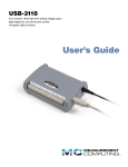
CIO-EXP32 Analog Multiplexer board User's Guide Document Revision 1, January, 2007 © Copyright 2007, Measurement Computing Corporation Your new Measurement Computing product comes with a fantastic extra — Management committed to your satisfaction! Thank you for choosing a Measurement Computing product—and congratulations! You own the finest, and you can now enjoy the protection of the most comprehensive warranties and unmatched phone tech support. It’s the embodiment of our mission: To provide data acquisition hardware and software that will save time and save money. Simple installations minimize the time between setting up your system and actually making measurements. We offer quick and simple access to outstanding live FREE technical support to help integrate MCC products into a DAQ system. Limited Lifetime Warranty: Most MCC products are covered by a limited lifetime warranty against defects in materials or workmanship for the life of the product, to the original purchaser, unless otherwise noted. Any products found to be defective in material or workmanship will be repaired, replaced with same or similar device, or refunded at MCC’s discretion. For specific information, please refer to the terms and conditions of sale. Harsh Environment Program: Any Measurement Computing product that is damaged due to misuse, or any reason, may be eligible for replacement with the same or similar device for 50% of the current list price. I/O boards face some harsh environments, some harsher than the boards are designed to withstand. Contact MCC to determine your product’s eligibility for this program. 30 Day Money-Back Guarantee: Any Measurement Computing Corporation product may be returned within 30 days of purchase for a full refund of the price paid for the product being returned. If you are not satisfied, or chose the wrong product by mistake, you do not have to keep it. These warranties are in lieu of all other warranties, expressed or implied, including any implied warranty of merchantability or fitness for a particular application. The remedies provided herein are the buyer’s sole and exclusive remedies. Neither Measurement Computing Corporation, nor its employees shall be liable for any direct or indirect, special, incidental or consequential damage arising from the use of its products, even if Measurement Computing Corporation has been notified in advance of the possibility of such damages. Trademark and Copyright Information Measurement Computing Corporation, InstaCal, Universal Library, and the Measurement Computing logo are either trademarks or registered trademarks of Measurement Computing Corporation. Refer to the Copyrights & Trademarks section on mccdaq.com/legal for more information about Measurement Computing trademarks. Other product and company names mentioned herein are trademarks or trade names of their respective companies. © 2007 Measurement Computing Corporation. All rights reserved. No part of this publication may be reproduced, stored in a retrieval system, or transmitted, in any form by any means, electronic, mechanical, by photocopying, recording, or otherwise without the prior written permission of Measurement Computing Corporation. Notice Measurement Computing Corporation does not authorize any Measurement Computing Corporation product for use in life support systems and/or devices without prior written consent from Measurement Computing Corporation. Life support devices/systems are devices or systems that, a) are intended for surgical implantation into the body, or b) support or sustain life and whose failure to perform can be reasonably expected to result in injury. Measurement Computing Corporation products are not designed with the components required, and are not subject to the testing required to ensure a level of reliability suitable for the treatment and diagnosis of people. HM CIO-EXP32.doc 3 Trademark and Copyright Information TracerDAQ, Universal Library, Harsh Environment Warranty, Measurement Computing Corporation, and the Measurement Computing logo are either trademarks or registered trademarks of Measurement Computing Corporation. Windows, Microsoft, and Visual Studio are either trademarks or registered trademarks of Microsoft Corporation LabVIEW is a trademark of National Instruments. CompactFlash is a registered trademark of SanDisk Corporation. XBee and XBee-PRO are trademarks of MaxStream, Inc. All other trademarks are the property of their respective owners. Information furnished by Measurement Computing Corporation is believed to be accurate and reliable. However, no responsibility is assumed by Measurement Computing Corporation neither for its use; nor for any infringements of patents or other rights of third parties, which may result from its use. No license is granted by implication or otherwise under any patent or copyrights of Measurement Computing Corporation. All rights reserved. No part of this publication may be reproduced, stored in a retrieval system, or transmitted, in any form by any means, electronic, mechanical, by photocopying, recording, or otherwise without the prior written permission of Measurement Computing Corporation. Notice Measurement Computing Corporation does not authorize any Measurement Computing Corporation product for use in life support systems and/or devices without prior written consent from Measurement Computing Corporation. Life support devices/systems are devices or systems which, a) are intended for surgical implantation into the body, or b) support or sustain life and whose failure to perform can be reasonably expected to result in injury. Measurement Computing Corporation products are not designed with the components required, and are not subject to the testing required to ensure a level of reliability suitable for the treatment and diagnosis of people. 4 Table of Contents Preface About this User’s Guide .......................................................................................................................7 What you will learn from this user’s guide.........................................................................................................7 Conventions in this user’s guide.........................................................................................................................7 Where to find more information .........................................................................................................................7 Chapter 1 Introducing the CIO-EXP32 ..................................................................................................................8 Overview: CIO-EXP32 features .........................................................................................................................8 Software features ................................................................................................................................................8 Chapter 2 Installing the CIO-EXP32 ......................................................................................................................9 What comes with your CIO-EXP32 shipment? ..................................................................................................9 Hardware .......................................................................................................................................................................... 9 Optional components ........................................................................................................................................................ 9 Additional documentation................................................................................................................................................. 9 Unpacking the CIO-EXP32 ................................................................................................................................9 Connecting to the A/D board............................................................................................................................10 Signal cable......................................................................................................................................................................10 Cabling.............................................................................................................................................................................10 Configuring the CIO-EXP32 ............................................................................................................................11 Power source....................................................................................................................................................................13 A/D board type ................................................................................................................................................................14 A/D Channel for EXP Output ..........................................................................................................................................14 EXP Gain .........................................................................................................................................................................15 Solder gap switches .........................................................................................................................................................16 Configuring the A/D board...............................................................................................................................16 Single-ended mode ..........................................................................................................................................................16 Range ...............................................................................................................................................................................16 Polarity.............................................................................................................................................................................17 Calibrating the CIO-EXP32..............................................................................................................................17 Chapter 3 Functional Details ...............................................................................................................................18 CIO-EXP32 inputs............................................................................................................................................18 Connecting to a signal source ..........................................................................................................................................18 Thermocouples .................................................................................................................................................19 Cold junction compensation.............................................................................................................................................20 Open thermocouple detect ...............................................................................................................................................20 Low pass filter .................................................................................................................................................................20 Ground reference .............................................................................................................................................................20 Input impedance...............................................................................................................................................................20 Amplification and thermocouples.....................................................................................................................20 Chapter 4 Programming and Developing Applications ....................................................................................22 Programming languages ...................................................................................................................................22 Packaged applications programs.......................................................................................................................22 Chapter 5 Specifications......................................................................................................................................23 Analog input .....................................................................................................................................................23 Cold junction compensation .............................................................................................................................23 Analog output ...................................................................................................................................................24 5 CIO-EXP32 User's Guide Digital input......................................................................................................................................................24 Power consumption ..........................................................................................................................................24 Environmental ..................................................................................................................................................24 Main connector and pin out ..............................................................................................................................25 6 Preface About this User’s Guide What you will learn from this user’s guide This user’s guide explains how to install, configure, and use the CIO-EXP32 so that you get the most out of its analog input and digital I/O features. This user’s guide also refers you to related documents available on our web site, and to technical support resources. Conventions in this user’s guide For more information on … Text presented in a box signifies additional information and helpful hints related to the subject matter you are reading. Caution! Shaded caution statements present information to help you avoid injuring yourself and others, damaging your hardware, or losing your data. <#:#> Angle brackets that enclose numbers separated by a colon signify a range of numbers, such as those assigned to registers, bit settings, etc. bold text Bold text is used for the names of objects on the screen, such as buttons, text boxes, and check boxes. For example: 1. Insert the disk or CD and click the OK button. italic text Italic text is used for the names of manuals and help topic titles, and to emphasize a word or phrase. For example: The InstaCal installation procedure is explained in the Quick Start Guide. Never touch the exposed pins or circuit connections on the board. Where to find more information The following electronic documents provide helpful information relevant to the operation of the CIO-EXP32. MCC's Specifications: CIO-EXP32 (the PDF version of the Specifications chapter in this guide) is available on our web site at www.mccdaq.com/pdfs/CIO-EXP32.pdf. MCC's Quick Start Guide is available on our web site at www.mccdaq.com/PDFmanuals/DAQ-Software-Quick-Start.pdf. MCC's Guide to Signal Connections is available on our web site at www.mccdaq.com/signals/signals.pdf. MCC's Universal Library User's Guide is available on our web site at www.mccdaq.com/PDFmanuals/sm-ul-user-guide.pdf. MCC's Universal Library Function Reference is available on our web site at www.mccdaq.com/PDFmanuals/sm-ul-functions.pdf. MCC's Universal Library for LabVIEW™ User’s Guide is available on our web site at www.mccdaq.com/PDFmanuals/SM-UL-LabVIEW.pdf. CIO-EXP32 User's Guide (this document) is also available on our web site at www.mccdaq.com/PDFmanuals/CIO-EXP32.pdf. 7 Chapter 1 Introducing the CIO-EXP32 Overview: CIO-EXP32 features The CIO-EXP32 is a 32-channel signal conditioning accessory board supported under popular Microsoft® Windows® operating systems. The CIO-EXP32 is used to expand the number of analog inputs and the range of amplification of DAS08 and DAS16 series boards. Using multiple CIO-EXP32 boards, a 16 channel A/D board can be expanded to up to 256 inputs; an 8 channel A/D board can be expanded to up to 128 inputs. The CIO-EXP32 board has two banks of 16 differential inputs that are multiplexed into one single-ended output channel. Four digital inputs are controlled by the A/D board's digital outputs, and are used to select one of the multiplexed channels for output. An on-board semiconductor sensor provides a cold junction compensation (CJC) reference for thermocouple applications. You select one channel on the A/D board to send the multiplexed analog output to. In addition, you can output the CJC signal to a second A/D board channel. You can enable an input filter, ground reference, and open thermocouple detect options for each channel using on-board solder gap switches. You specify the gain of the multiplexer with an onboard gain switch. You can power the CIO-EXP32 internally from the A/D board, or externally from the computer's +5 V power supply connectors. The CIO-EXP32 board is mounted externally to the PC. It can be placed in the open on a benchtop or in a case. Software features For information on the features of InstaCal and the other software included with your CIO-EXP32, refer to the Quick Start Guide that shipped with your device. The Quick Start Guide is also available in PDF at www.mccdaq.com/PDFmanuals/DAQ-Software-Quick-Start.pdf. Check www.mccdaq.com/download.htm for the latest software version. 8 Chapter 2 Installing the CIO-EXP32 What comes with your CIO-EXP32 shipment? The following items are shipped with the CIO-EXP32. Hardware CIO-EXP32 Optional components You can also order the following MCC products to use with your CIO-EXP32. C37FF-x C-EXP2DAS16-10 C-PCPOWER-10 BP-POWER Additional documentation In addition to this hardware user's guide, you should also receive the Quick Start Guide (available in PDF at www.mccdaq.com/PDFmanuals/DAQ-Software-Quick-Start.pdf). This booklet supplies a brief description of the software you received with your CIO-EXP32 and information regarding installation of that software. Please read this booklet completely before installing any software or hardware. Unpacking the CIO-EXP32 As with any electronic device, you should take care while handling to avoid damage from static electricity. Before removing the CIO-EXP32 from its packaging, ground yourself using a wrist strap or by simply touching the computer chassis or other grounded object to eliminate any stored static charge. If any components are missing or damaged, notify Measurement Computing Corporation immediately by phone, fax, or e-mail: Phone: 508-946-5100 and follow the instructions for reaching Tech Support. Fax: 508-946-9500 to the attention of Tech Support Email: [email protected] 9 CIO-EXP32 User's Guide Installing the CIO-EXP32 Connecting to the A/D board There are two 37-pin D type connectors on the CIO-EXP32 — P1 and P2. They are wired 1:1. Connector P1 is labeled NEXT EXP, and is provided to daisy chain additional CIO-EXP32 boards. Use a C37FF-x cable to daisy chain the CIO-EXP32 boards together. Do not exceed 50 feet in length. Signals may be connected from the CIO-EXP32 board to the A/D board through one of two types of cables. The cable used depends upon the type of A/D board you are connecting to. The table below lists the CIO-EXP32 board's connectors and compatible cables. Board connector, cables, and accessory equipment Connector type Compatible cables with connector P1 Compatible cables with connector P2 P1 and P2: 37-pin D type connector C37FF-x (connecting to additional CIO-EXP32 boards) C37FF-x (connecting to a DAS08 board) C-EXP2DAS16-10 (connecting to a DAS16 board) Signal cable The CIO-EXP32 signal connector is nearly a mirror of the CIO-DAS08 signal cable. NC / LLGND LLGND / Output Output 9 Output 10 Output 11 Output 12 Output 13 Output 14 Output 15 MUX Addr 4 MUX Addr 3 MUX Addr 2 MUX Addr 1 NC NC NC NC NC +12V PC Bus 19 18 17 16 15 14 13 12 11 10 9 8 7 6 5 4 3 2 1 37 36 35 34 33 32 31 30 29 28 27 26 25 24 23 22 21 20 Output 0 Output 1 Output 2 Output 3 Output 4 Output 5 Output 6 Output 7 +5V Power GND NC NC NC NC NC NC NC -12V PC Bus Figure 1. Connector P2/P1 Cabling 37 20 37 19 The red stripe identifies pin # 1 1 Figure 2. C37FF-x cable 10 20 19 1 CIO-EXP32 User's Guide Installing the CIO-EXP32 Connecting to a DAS08 Series A/D board Leave the A/D BOARD TYPE jumper in the default DAS08 position. Use a C37FF-x cable to connect to DAS08 series boards. Connecting to a DAS16 Series A/D Board Set the A/D BOARD TYPE jumper to the DAS16 position. Connection to a DAS16 series board requires a special 37-conductor cable (C-EXP2DAS16-10) since the pin relationship of the CIO-EXP32 and DAS16 signals is not 1:1. Refer to the C-EXP2DAS16-10 cable pin out table below. C-EXP2DAS16-10 cable pin out P1 (MUX) P2 7 8 9 10 11 12 13 14 15 16 17 18 19 28 29 30 31 32 33 34 35 36 37 N/C 23 4 22 3 11 12 13 14 15 16 17 18 19 7 1 30 31 32 33 34 35 36 37 Shell Shield Information on signal connections General information regarding signal connection and configuration is available in the Guide to Signal Connections (available at www.mccdaq.com/signals/signals.pdf). 11 CIO-EXP32 User's Guide Installing the CIO-EXP32 Configuring the CIO-EXP32 Before using the CIO-EXP32, there are switches and jumpers to set, and one or more cables to install. Please turn the PC power OFF before proceeding. The CIO-EXP32 is shipped with the factory-default settings listed in the following table. Factory-configured default settings Jumper/switch Description Default setting Power source select switch S3 A/D BOARD TYPE jumper EXP OUTPUT TO DAS jumper +5V power switch that sets the power source to internal or external INT (internal +5V PC power) Selects DAS08 or DAS16 compatibility Selects the A/D board channel to connect the multiplexed analog output to. CJC OUTPUT TO DAS jumper Selects the A/D board channel to connect the CJC output to. GAIN switches S1 and S2 Four DIP switches per each bank of 16 inputs that set the gain of the differential amplifier. Three 'connect pads' per channel on the etch side (under side) of the CIO-EXP32 board. Bridge each pad to configures its associated input channel as follows: Bridge the V pads to enable open thermocouple detection for the associated input channel. Bridge the C pads to connect a 1 µF capacitor across the signal high and low inputs, forming a low-pass filter having a 7 Hz cutoff. Bridge the G pads to enable a reference to ground for the associated input channel. DAS08 CH 0 to 15: 0 CH 16 to 31: 1 (EXP multiplexed output connects to channel 0 and 1 on the A/D board) 7 (CJC circuit connects to channel 7 on the A/D board) Gain = 1 (all gain switches OFF) V, C and G solder bridge switches (one for each input channel) Open pads (all are not bridged) Figure 3 shows the location of the board jumpers, switches, and connectors. The solder bridges are on the under side of the board, and are not shown in the figure. EXP and CJC Output to A/D Board Type DAS channel jumpers jumper P2 connector (DAS) P1 connector (Next EXP) Gain switch S2 Gain switches S1 Power source switch S3 External power connector P29 Figure 3. Switch, jumper, and connector locations Before using the CIO-EXP32, verify that the board is configured with the settings that you want. Review the following information to change the default configuration of a jumper, switch, or solder gap. 12 CIO-EXP32 User's Guide Installing the CIO-EXP32 Power source You can supply +5V DC power to the via the 37-conductor cable from the A/D board in the PC (internal), or via a separate optional power cable connected directly to the PC power supply (external). The internal method is adequate for powering up to two CIO-EXP32 boards. Supply external power (connect the C-PCPOWER-10 power cable) when: More than two CIO-EXP32 boards are used with one A/D board. The A/D board in use does not supply +5V to its connector Configure the CIO-EXP32 board’s power source with switch S3 for either internal or external power. Figure 4 shows this switch configured in both positions. +5V +5V S3 EXT S3 INT EXT INT External power Internal power +5V power from the PC via 37 conductor signal cable +5V power from the PC via 2 conductor optional C-PCPOWER-10 power cable Figure 4. Power source-select switch External +5 V PC power connections You can power the CIO-EXP32 with your computer’s +5V power supply using the optional C-PCPOWER-10 cord. Each end of the cable has a keyed Molex® type connector. To connect to your computer’s power connectors, do the following: 1. Turn off power to the computer and remove the cover. 2. Connect the black cable with the white Molex® type connectors to one of the unused PC expansion power connectors from the PC power supply. They are keyed, so the cable will plug into the expansion connector easily when they are aligned (see Figure 5). Personal Computer Power cable J3 to PC Power Supply Signal cable P2 to CIO-DAS08 analog board DC/DC CIO-EXP32 Figure 5. External power cable installation 3. Run the power cable out the back of the computer through an expansion slot or other opening and replace the cover on the computer. 13 CIO-EXP32 User's Guide Installing the CIO-EXP32 You can alternatively connect the C-PCPOWER-10 to a BP-POWER adaptor to bring PC power out of the computer. This adaptor provides three standard power connectors mounted on a backplate. Details on this product are available on our web site at www.mccdaq.com/products/accessories.aspx. Caution! Be careful not to pinch the cable when you replace the cover—if this cable is cut, the resulting short circuit can damage the computer. 4. Connect the other end of the power cord to the connector labeled "OPTIONAL EXTERNAL +5V POWER" (P15) on the CIO-EXP32. This end is keyed also. Refer to Figure 3 for the location of this connector. 5. Slide the power source select switch (S3) to the EXT position. A/D board type Use the 4-pin jumper labeled A/D BOARD TYPE to configure the CIO-EXP32 for use with the DAS08 family of boards or the DAS16 family of boards. Place the jumper in the position for the type of A/D board you are using with the CIO-EXP32. Figure 6 shows the jumper configured with its default setting of DAS08. LLGND DAS08 DAS16 P2, pin19 P2, pin 18 Figure 6. Board type select jumper A/D Channel for EXP Output Select a separate A/D channel for each CIO-EXP32 output that you plan to use. Each CIO-EXP32 has three potential signals — the output of each of the two banks of 16 multiplexed inputs, and the output of the CJC circuit. The output of the CIO-EXP32 selected channel is an input to the A/D board. Three rows of 16 jumper pairs located near the 37-pin connectors are labeled with A/D board channel numbers (see Figure 7). These channel numbers designate which of the A/D board's input channels will be connected to the MUX board’s output(s). Each CIO-EXP32 output, if used, must be exclusively assigned to an A/D channel using these jumpers. In other words, for all CIO-EXP32 boards attached to an A/D board, only one jumper on any of the jumper blocks should be assigned to a particular channel. Figure 7 shows the layout of the jumper blocks on the CIO-EXP32. EXP OUTPUT TO DAS EXP 0-15 0 1 2 3 4 5 6 7 8 9 10 11 12 13 14 15 EXP 16-31 DAS8/16 DAS16 ONLY CJC CJC OUTPUT TO DAS These jumpers are for boards with 16 channels only, such as the CIO-DAS16 in 16 channel mode. Figure 7. EXP Channel Select and CJC Select jumper blocks The CIO-EXP32 has two banks of 16 input channels. Each bank is multiplexed into one output. These two outputs connect to the jumper block labeled EXP OUTPUT TO DAS. This jumper block determines which analog input channels of the A/D board in the computer is connected to the outputs from the CIO-EXP32 board. 14 CIO-EXP32 User's Guide Installing the CIO-EXP32 The CIO-EXP32 also has a semiconductor temperature sensor on board to measure the temperature of the board in the region of the screw terminals. The temperature at the screw terminals is needed when thermocouples are used with the CIO-EXP32. The temperature at the screw terminals is called the Cold Junction temperature, and is needed to accurately calculate thermocouple temperature. This is known as Cold Junction Compensation. When a CIO-EXP32 channel is used with a thermocouple, install the CJC OUTPUT TO DAS jumper in the desired channel location. If you are not using thermocouples, do not install it. Select the A/D board channel to connect the multiplexed analog output to using the jumpers labeled EXP OUTPUT TO DAS. Channels 0-15 are connected by default to A/D board channel 0. Channels 16-31 are connected by default to A/D board channel 1. Select the A/D board channel to connect the CJC output to (if required) using the jumpers labeled CJC OUTPUT TO DAS. CIO-EXP CJC is connected by default to A/D channel 7. Channel selection for the DAS08 family The DAS08 family of boards has eight channels of input, so only CIO-EXP32 jumper positions 0-7 are valid. Many boards in the DAS08 family of boards have single-ended inputs, which is the correct type to connect to a CIO-EXP32. If the inputs on the board type you are using are differential, they must be converted to singleended inputs (refer to the hardware user's manual supplied with your A/D board for more information). You can connect up to eight banks of CIO-EXP32 inputs to a DAS08 series board, for a total of 128 inputs. Channel selection for the DAS16 family The CIO-EXP32 jumper positions 0-7 and 8-15 can be used with the CIO-DAS16. You can connect up to 16 banks of CIO-EXP32 inputs to a DAS16 series board, for a total of 256 inputs. Most of the DAS16 family of A/D is switch-selectable for either 8 differential or 16 single-ended channels. Set the switch for 16-channel, single-ended mode. EXP Gain The CIO-EXP32 has two banks of four DIP switches (S1 and S2) that control the gain of the differential amplifier. Figure 8 shows a typical switch. x500 4 x200 3 x100 2 x10 1 ON = left Figure 8. Gain switch The gain associated with a switch is 'ON' when the switch is to the left, and 'OFF' when the switch is to the right. The gains are additive, so a total of 16 different gains are possible. The board is shipped with all switches off (gain =1). The switch shown in Figure 8 is configured for a gain of 700 (500 + 200). For most thermocouple applications, the gain should be set to at least 100. Refer to the section Amplification and thermocouples on page 20 for data on setting optimum amplifier gains when using thermocouples. For most other applications, the gain should be set to result in output signal levels as close to ±5V or ±10V (depending on the range setting on the A/D board) as possible. 15 CIO-EXP32 User's Guide Installing the CIO-EXP32 Solder gap switches Each analog input channel on the CIO-EXP32 has three dedicated solder gap switches labeled C, V, and G on the circuit side (under side) of the board. Each solder gap switch enables a different thermocouple option. A typical set of solder gap switches is shown here. VCG Figure 9. Solder gap switches (typical per channel) A solder gap switch has two pads. Turn on each switch by soldering the pads together to close them — this is called a solder bridge. When closed, or bridged, the pads connect resistors and capacitors to the input signals and enable the following options: Open thermocouple detect (V pad) — enables open thermocouple detection to alert you if a thermocouple breaks. Note that your software program must be designed to recognize when a negative full-scale condition exists, since the input is pulled to minus full-scale if the thermocouple wire is broken or disconnected. Input filter (C pad) — connects a 1 µF capacitor across the signal high and low inputs. This forms a 7 Hz low pass filter that filters out signal noise that is picked up on the thermocouple wire. Input ground reference (G pad) — provides a reference to ground through a 100 k resistor. This reference prohibits floating thermocouple readings. You should bridge the C and G pads with solder for each channel that you install a thermocouple. Bridging these pads reduces the noise present when you take temperature readings, and helps to obtain a more accurate temperature reading. The C, V, and G pads are all open when the board is shipped. How to add and remove a solder bridge To add a solder bridge to a solder gap switch, place a drop of solder on one of the pads and pull the soldering iron perpendicular to the pads from their center. To remove a solder bridge, slide the soldering iron toward one pad or the other. Take care not to overheat the solder, or the pads may lift. Configuring the A/D board Use InstaCal to change the following configuration options on your DAS08 or DAS16 Series board. Single-ended mode DAS08 setup: The input mode of the A/D board must be single-ended to be compatible with the CIO-EXP32 outputs. Some of the boards in the DAS08 series have differential inputs that can be converted to single-ended inputs. Refer to the user's manual for your hardware for information on conversion to single-ended inputs. DAS16 setup: The input mode of the A/D board must be single-ended to be compatible with the CIO-EXP32 outputs. Most of the DAS16 series is switch-selectable for either 8 differential or 16 single ended inputs. When used with the CIO-EXP32, set the switch to 16 channel, single-ended mode. Range If the range of your A/D board is switch-selectable, and you are using thermocouples, set the range of the DAS board to ±5 V, if available, or ±10 V if not. Some software packages base the calculation of temperature on these ranges only. If you are not using thermocouples, set the range of the DAS board to accommodate the maximum output expected from the CIO-EXP32 board. 16 CIO-EXP32 User's Guide Installing the CIO-EXP32 Polarity If your A/D board has a UNI / BIP switch for setting the range to either unipolar or bipolar, the preferred setting is BIP (bipolar). If the range on your A/D board is fully programmable, the software you use for temperature measurement will determine the correct range to use. Calibrating the CIO-EXP32 You should calibrate the CIO-EXP32 after you first connect to a A/D board, if you change the gain setting of the input amplifier, and at 6 month intervals. 17 Chapter 3 Functional Details CIO-EXP32 inputs The CIO-EXP32 inputs are screw terminals which will accept 12-22 AWG wire. Each channel has a screw terminal for signal high, signal low and ground. The inputs are differential, which require three connections from the signal source to the CIO-EXP32 — Signal High, Signal Low, and Signal Ground. A typical connection is shown in Figure 10. Signal High Signal Low Low Level Ground Figure 10. Differential channel connections Figure 11 shows a block diagram of the board’s 16 analog inputs. One input is selected by the four MUX address lines that are controlled by the A/D board. CH15 HIGH CH15 LOW 4 MUX ADDR MUX HI-507 EXP out to the DAS board CH8 HIGH CH8 LOW AMP INA1 10 GND Ground CH7 HIGH CH7 LOW MUX HI-507 CH0 HIGH CH0 LOW Gain Switch GND Figure 11. Analog inputs block diagram Connecting to a signal source You can connect analog inputs to the CIO-EXP32 in either a floating differential or differential configuration. Before connecting to a signal source, measure the voltage between the signal ground at the signal source and ground at the PC. Do not connect to a signal source if the voltage difference exceeds 10 V, as you will not be able to obtain a reading. Caution! DO NOT connect to the signal if the voltage exceeds 30 V — voltages over 30 V will damage the board and possibly the computer. 18 CIO-EXP32 User's Guide Functional Details Floating differential input A floating differential input has two wires from the signal source, and a 100 K ground reference resistor installed at the CIO-EXP32 input. The two signals from the signal source are Signal High (CH#-HI) and Signal Low (CH#-LO). The reference resistor is connected between the CH#-LO and #-G (Signal Ground) pins. Use a floating differential hookup when the signal source is floating with respect to ground, such as a battery, 420 mA transmitter or thermocouple, and the lead lengths are long or subject to electromagnetic interference (EMI) pickup. A thermocouple is an example of a floating differential signal source. Instead of using an external 100 K resistor, add a solder bridge between the 'G' pads to enable a ground reference. The floating differential input will reject up to 10 V of EMI. Caution! Use a voltmeter to verify that the signal source is floating, or you may damage the CIO-EXP32 and/or your computer. Differential input A differential signal uses three wires from the signal source — Signal High (CH#-HI), Signal Low (CH#-LO) and Signal Ground (#-G). With a differential configuration, you can connect the CIO-EXP32 to a signal source with a ground that is different from the PC ground, but with less than 10 V difference, and still make a true measurement of the signal between CH# HI and CH# LO. An example of this is a laboratory instrument with its own wall plug, where there are sometimes differences in wall grounds between outlets. Information on signal connections For general information about signal connection and configuration, refer to the Guide to Signal Connections on our web site at www.mccdaq.com/signals/signals.pdf. Thermocouples A thermocouple is made of two dissimilar wires that react electrically when in contact with each other. The reaction produces a voltage which is dependent on the temperature at the point where the two metals touch. There is a reaction at every point where dissimilar metals (the thermocouple wire) touch, including the screw terminal where the thermocouple wire is connected to the CIO-EXP32 board. To process thermocouple signals, the CIO-EXP32 provides cold junction compensation (CJC), open thermocouple detect (OTD) and stable amplification for accurate temperature measurements. Figure 12 shows a thermocouple connected to one channel of the CIO-EXP32. The thermocouple has a positive and a negative lead. If you're not sure which is the positive lead and which is the negative lead, make a test hookup and use a match to heat the thermocouple. If the temperature reading goes down, switch the leads. 3.9M -15 V Thermocouple positive lead 10K High C 1 µF 10K Low Thermocouple negative lead High V Low Ground 100K G Ground C = Filter capacitor, pad open. V = Open TC Detect, pad open. G = Reference to ground, pad open. Pads are located on the circuit side. All pads must be closed when thermocouples are used. Figure 12. Typical thermocouple connection 19 CIO-EXP32 User's Guide Functional Details Cold junction compensation The CIO-EXP32 has a semiconductor temperature sensor to measure the temperature of the board around the screw terminals—this is called the cold junction temperature. This sensor provides a stable, accurate and linear output which is temperature-dependent. The cold junction temperature is required to accurately calculate the thermocouple temperature. This is known as cold junction compensation (CJC). You can map the sensor output to one of the A/D board's analog inputs using the CJC output to DAS jumper block. The CJC reference is required for accurate temperature readings The CJC temperature reference is universally used by software to compensate for the voltage induced at the cold junction (the area around the screw terminals). If you don't supply a CJC reference your temperature readings may be inaccurate. Open thermocouple detect You enable open thermocouple detect (OTD) by closing the channel’s associated 'V' pad with a solder bridge. OTD applies a full-scale negative voltage to the high side of the thermocouple signal. If a thermocouple opens, the OTD voltage drives the signal on that channel to negative full-scale. Design your software program to recognize when a negative full-scale condition exists, since the input is pulled to negative full-scale if the thermocouple wire is broken or disconnected. Most software is set up to alarm for an open thermocouple when a temperature falls to negative full-scale. The CIO-EXP32 will accurately measure thermocouples when the 'V' pad is open, but without OTD protection enabled. Low pass filter A low pass filter is implemented by closing the 'C' pad. When bridged, a 1 µF capacitor is connected across the signal’s high and low inputs, forming a low-pass filter. The bandwidth of this filter is 7 Hz. Signals changing at rates greater than 7 times per second are damped. The low pass filter helps to reject noise picked up along the thermocouple wire. Since temperature measurement is generally a ‘low frequency’ application, the filter does not affect the temperature measurement. The CIO-EXP32 will accurately measure thermocouples when the 'C' pad is open, but the measurements may fluctuate due to noise present on the thermocouple wire. Ground reference The CIO-EXP32 inputs are fully differential, which help reject noise on thermocouple wires. Close the ‘G’ pad thermocouples to work properly. The 'G' pad provides a reference from ground to the analog low input via a 100 K resistor. When closed, enough current passes through the resistor to provide a reference to ground. The analog high and low inputs are still able to float within the common mode range. Input impedance When you leave the V and G pads open, the input impedance is greater than 100 M ohms. When you short the V and G pads, the input impedance is 100 k ohms. Amplification and thermocouples The voltage from a thermocouple is very low and must be amplified to take advantage of the A/D board’s full resolution. Use the GAIN switch to set the amplification of the CIO-EXP32 board's 16 analog inputs (see Figure 8 on page 15). The following table lists the theoretical amplifier output voltage at maximum temperature for each gain. In most cases, the range on the A/D board is set to ±5 V. The maximum voltage for some thermocouple/gain combinations can exceed the maximum A/D input range (typically 5 V), or even the maximum output voltage of the CIO-EXP32 board (±10 V). 20 CIO-EXP32 User's Guide Functional Details Output voltage vs gain at maximum temperature Type J K T E S R Min Temp °C 0 −200 −200 −200 0 0 Max Temp °C mV at Max Gain / Output Volts @ Max Temp 100 200 300 500 800 750 1250 42.28 50.63 4.2 5.1 8.5 10.1 12.7 15.2 21.1 25.3 33.8 40.5 350 900 17.82 68.78 1.8 6.9 3.6 13.8 5.3 20.6 8.9 34.4 14.3 55.0 1450 1450 14.97 16.74 1.5 1.7 3.0 3.3 4.5 5.0 7.5 8.4 12.0 13.4 The table below lists the maximum readable temperatures for each gain and thermocouple type for an A/D range of ±5V. Gain vs maximum readable temperatures Type J K T E S R Gain / Max. Readable Temps. with A/D Range = ±5 V 10 100 200 300 500 800 MAX MAX MAX MAX MAX MAX MAX 1232 °C MAX 661°C MAX MAX 457 °C 602 °C MAX 350 °C MAX MAX 307 °C 406 °C 330 °C 244 °C MAX 1445 °C 186 °C 246 °C 214 °C 152 °C 1035 °C 961°C 117 °C 152 °C 140 °C 98 °C 697 °C 658 °C To read the maximum usable temperature for type K and E thermocouples, set the gain to X10 or less. After you change the gain setting, calibrate the CIO-EXP32 using the InstaCal utility. 21 Programming and Developing Applications Chapter 4 After following the installation instructions in Chapter 2, your board should now be installed and ready for use. In general there may be no correspondence among registers for different boards. Software written at the register level for other models will not function correctly with your board. Programming languages Measurement Computing’s Universal Library provides access to board functions from a variety of Windows programming languages. If you are planning to write programs, or would like to run the example programs for Visual Basic or any other language, please refer to the Universal Library User's Guide (available on our web site at www.mccdaq.com/PDFmanuals/sm-ul-user-guide.pdf). Packaged applications programs Many packaged application programs now have drivers for your board. If the package you own does not have drivers for your board, please fax or e-mail the package name and the revision number from the install disks. We will research the package for you and advise how to obtain drivers. Some application drivers are included with the Universal Library package, but not with the application package. If you have purchased an application package directly from the software vendor, you may need to purchase our Universal Library and drivers. Please contact us by phone, fax or e-mail: Phone: 508-946-5100 and follow the instructions for reaching Tech Support. Fax: 508-946-9500 to the attention of Tech Support Email: [email protected] 22 Chapter 5 Specifications Typical for 25 °C unless otherwise specified. Specifications in italic text are guaranteed by design. Analog input Table 1. Analog input specifications Parameter Specification Number of channels Input range Gain Calibration 32 differential (2 banks of 16) ±10 V Switch selectable by bank, additive values of X1, X10, X100, X200 and X500 Two offset potentiometers per bank (16 channels) and one Cold Junction Compensation adjustment potentiometer per board. Gain = 1 0.002% typical, 0.02% max Gain = 10 0.005% typical, 0.05% max Gain = 100 0.01% typical, 0.1% max Gain = 200 0.02% typical, 0.2% max Gain = 500 0.05% typical, 0.5% max Gain = 1 0.0005% typical, 0.005% Gain = 10 0.001% typical, 0.01% max Gain = 100 0.002% typical, 0.01% max Gain = 200 0.003% typical, 0.01% max Gain = 500 0.005% typical, 0.02% max Gain = 1 ± 20 ppm / °C Gain = 10 ± 20 ppm / °C Gain = 100 ± 40 ppm / °C Gain = 200 ± 60 ppm / °C Gain = 500 ± 100 ppm / °C Offset ± 15 µV / °C ±10 V 90 dB 7 Hz, selectable through solder bridge (C pad) -50 mV at positive input when thermocouple is open, selectable through solder bridge (V pad) 100k ohms to ground, selectable through solder bridge (G pad) V and G pads open: 2 nA typical, 6 nA max V and G pads open: >100 Meg Ohms min V and G pads shorted 100 k Ohms min Power on: ±35 V Power off: ±20 V Gain error Non-linearity Temperature coefficient Common mode range CMRR @ 60 Hz Input filter Open thermocouple detect Input ground reference Input leakage current Input impedance Absolute maximum input voltage Cold junction compensation Table 2. Cold junction compensation specifications Parameter Specification CJC output voltage CJC zero crossing 24 mV / °C 0 mV at 0 °C 23 CIO-EXP32 User's Guide Specifications Analog output Table 3. Analog output specifications Parameter Specification Number of channels Output voltage Configuration Current drive Output coupling Output impedance 2 ±10 V Single–ended ±5 mA DC 0.1 Ohms max Digital input Table 4. Analog input specifications Parameter Specification Digital input: 74LS14 Configuration Number of channels Input high Input low Four bits for selecting multiplexer channel 0 through 15 4 input 2.0 volts min, 7 volts absolute max 0.8 volts max, -0.5 volts absolute min Power consumption Table 5. Power consumption specifications Parameter Specification +5 V 300 mA typical, 390 mA max Environmental Table 6. Environmental specifications Operating temperature range Storage temperature range Humidity 0 to 60 °C -40 to 100 °C 0 to 90% non-condensing 24 CIO-EXP32 User's Guide Specifications Main connector and pin out Table 7. Connector specifications Connector type Compatible cables with connector P1 Compatible cables with connector P2 P1 and P2: 37-pin D type connectors C37FF-x (connecting to additional CIO-EXP32 boards) C37FF-x (connecting to a DAS08 board) C-EXP2DAS16-10 (connecting to a DAS16 board) Table 8. Connector pin out Pin 1 2 3 4 5 6 7 8 9 10 11 12 13 14 15 16 17 18 19 Signal Name +12V PC Bus NC NC NC NC NC MUX Addr 1 MUX Addr 2 MUX Addr 3 MUX Addr 4 Output 15 Output 14 Output 13 Output 12 Output 11 Output 10 Output 9 LLGND / Output NC / LLGND Pin 20 21 22 23 24 25 26 27 28 29 30 31 32 33 34 35 36 37 Signal Name -12V PC Bus NC NC NC NC NC NC NC Power GND +5V Output 7 Output 6 Output 5 Output 4 Output 3 Output 2 Output 1 Output 0 25 Declaration of Conformity Manufacturer: Address: Category: Measurement Computing Corporation 10 Commerce Way Suite 1008 Norton, MA 02766 USA Electrical equipment for measurement, control and laboratory use. Measurement Computing Corporation declares under sole responsibility that the product CIO-EXP32 to which this declaration relates is in conformity with the relevant provisions of the following standards or other documents: EU EMC Directive 89/336/EEC: Electromagnetic Compatibility, EN55022 (1987), EN50082-1 Emissions: Group 1, Class B EN55022 (1987): Radiated and Conducted emissions. Immunity: EN50082-1 IEC 801-2 (1987): Electrostatic Discharge immunity, Criteria A. IEC 801-3 (1984): Radiated Electromagnetic Field immunity Criteria A. IEC 801-4 (1988): Electric Fast Transient Burst immunity Criteria A. Declaration of Conformity based on tests conducted by Chomerics Test Services, Woburn, MA 01801, USA in November, 1995. Test records are outlined in Chomerics Test Report #EMI0168A.95. We hereby declare that the equipment specified conforms to the above Directives and Standards. Carl Haapaoja, Director of Quality Assurance Measurement Computing Corporation 10 Commerce Way Suite 1008 Norton, Massachusetts 02766 (508) 946-5100 Fax: (508) 946-9500 E-mail: [email protected] www.mccdaq.com