
1
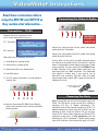
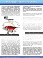
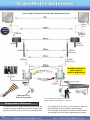
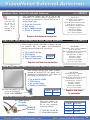
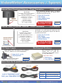
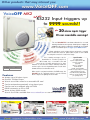
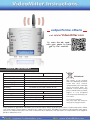
Version 2.0
2012
TM
✓ Digital Data Transmission
for cleaner, sharper images over longer distances
✓ Privacy Pairing Function
for private video transmission, helping comply
with the Data Protection Act
✓ Reverse
IR Transmission
sends IR signals from receiver to transmitter for
remote control of equipment
✓ Handshake Routine
2 way reporting for maximum security
✓ Whisper Mode
listens for data at a low power for energy efficiency
Digital, Reliable Transmission, up to 1Km!*
Typical Installation
*Additional antennas required for 1km
More info at:
www.videoMitter.com
TM
Things the professionals know!
Tip
- different sites will affect the range.
1. The signal will not go through hills. The density of the
hill and water it contains in the soil absorbs the
microwave signal.
2. The signal will go through branches of trees but
remember that microwave signals will be attenuated
greatly by water. Leaves and plants are full of water so
the distance is reduced. To help, fit the best directional
antennas and/or avoid the trees.
Foil backed
plasterboard
Rain or
snow
Directional antenna
blocks out the
interference
Router or other
RF equipment
2
3. In modern buildings sometimes the structure is lined
with “FOIL”. This can reflect or “ground” the wireless
signal. Avoid transmitting through such “shields”. If wiring
is not an option then use the powerful directional
antennas to help or mount the Rx unit on the exterior of
a building in an ABS box.
4.
Remember if you are installing on a day when the
weather is good the signal will be good. However, when
it is raining heavily the microwave signal will be absorbed
by the rain and reduce the distance. So always keep the
distance to a minimum and allow for the use of additional
directional antennas.
5. On some sites you may have other RF equipment that
can interfere with the VideoMitters and reduce the range
or cause poor performance. The best solution for a site
like this is fitting directional antennas as they help “block”
out the interference.
TM
Things the professionals know!
Tip
- getting maximum performance when fitting multiple pairs of
VideoMitters on the same site.
When you are fitting multiple pairs of VideoMitters on the
same site, it's really important to have some knowledge
of good installation practice of wireless devices.
When you are installing any transmission device, it's
always good practice to keep it a reasonable distance
away from another transmission devices. This is because
the signal from one could overwhelm the other leading to
poor performance of one or both devices. Poor
performance may result in intermittent loss of signal or
non operation.
The VideoMitters are actually “transceivers” this means
that the “transmitters” and the “receivers” BOTH transmit
and means you also need to keep pairs of receivers a
reasonable distance from each other.
1-2 mtr
Two transmitters close together with omni
directional antennas, the signal from each
can overwhelm each other. Try keeping them
at least 1-2 metres apart.
The standard antenna that the VideoMitters are supplied
with is called an “Omni-directional” antenna, this means
it transmits in “all” directions. So when two transmitters
are close to each other they will be transmitting signals at
each other as well as the receiver which is why you need
to keep them spaced apart, spacing of 1-2 metres is
required between each transmitting device.
Professional installers of wireless equipment would
always use “directional” antennas so that one transmitter
is aiming its signal directly at its own receiver and
therefore the signal is far less likely to interfere with
another transmitter located near it.
So on sites with multiple pairs of video transmitters, it is
always recommended to use directional antennas for a
professional installation.
Adding directional antennas means the
transmitters next to each other don’t
overwhelm each other with erroneous
transmission.
The added benefit of the directional antennas is that they
will also add increased range making the whole system
more reliable.
Tip
The VideoMitter has 20 channels so theoretically 20
pairs can be used per site however it is only
recommended to use 4 pairs per site to minimise any
chance of cross interference.
Using directional antennas
means the VideoMitters can
be fitted closer together.
3
TM
Read these instructions before
using the MIT100 and MIT150 as
they contain vital information...
Connections - TX/RX
Although identical in appearance each
unit is clearly marked on the face as:
TX - Transmitter
Connecting the Video & Audio
1
2
3 4 5
Connect the video input feed to the yellow video phono
socket (3) on the Transmitter.
RX - Receiver
Both units have the following connections
1 - Audio Right via a phono socket
2 - Audio Left via a phono socket
3 - Video connection via a phono socket
4 - Infra Red socket
5 - 12v D.C. power connection via a spring loaded
terminal strip
Connect the video output feed to the yellow video phono
socket (3) on the Receiver.
If using audio, use the red (1) and white (2) phono inputs
and connect to the audio R and L for stereo or L only for
mono. A video/audio lead with phono connections at both
ends is supplied. You may need to fit the CON003 Phono
to BNC converter to the yellow phono connector if the
video input feed has a BNC connection. The video/audio
lead supplied is 180cm long. If you need to use an
alternative lead, remember that both video and audio
signals require both a signal AND a ground connection to
complete the circuit.
Converts a Phono Plug
into a BNC Plug
1
2
3 4 5
6- Antenna Connection (RP SMA Female Socket)
connects to extension cables or direct connection
antenna models.
4
WARNING
POLARITY
SENSITIVE
6
CON003
Powering the Units
Both the transmitter and receiver need a power supply unit
(PSU). The PSU for the receiver needs to be capable of
supplying 12V D.C. @ 150mA continuously. The
transmitter needs a PSU capable of supplying 12V D.C. @
200mA continuously. Please keep this in mind if you are
intending to share a PSU for both the TX unit and your
chosen CCTV camera. When choosing any PSU for CCTV
equipment ensure that it is fully regulated or you risk
damaging the CCTV equipment. A good quality supply
such as the “AntiHum” series featured on page 14 is ideal.
TM
The spring loaded terminal strip (5) that connects power
to the units is clearly marked with the correct connection
polarity.
+ -
12 V
May also be
a red core.
12V
DC
5
WARNING
POLARITY
SENSITIVE
0V
Figure 1
If you are using an “AntiHum.com” PSU and have cut off
the D.C power plug you will be left with a two-cored cable.
The black core with the white strip is +12V; the solid black
core is 0V (figure 1). Take extreme care here as the TX
is polarity sensitive and must be correctly connected by
pressing the orange spring clips (5) in with a small
screwdriver and placing the power cable into the
respective hole below, ensuring positive and negative
cables are connected according to the diagrams shown.
If you are using any other PSU, you MUST check the
polarity of the power supply that you are using to ensure
the power is connected correctly.
Always check this with the actual PSU instructions!
Receiver end and it is necessary to ensure that the
BLACK IR connection cable is fitted to the RECEIVER
and the ORANGE connector is fitted to the
TRANSMITTER.
IR Receiver connection from TX unit
If you want to use the Infra Red receiver option ensure that
the IR connection cable with the ORANGE connector is
fitted to the TRANSMITTER IR socket (4).
TX
ORANGE
Note - The IR from the orange lead only transmits a short
distance to the device its being used to control, therefore
please place the end of this lead within 0.5 mtrs of the IR
input.
IR input connection to RX unit
If you want to use the Infra Red transmit option ensure
that the IR connection cable with the BLACK connector is
fitted to the RECEIVER IR socket (4).
RX
BLACK
Infra Red Transmissions
Infra Red transmission is also available on the
VideoMitter. This provides additional functionality such as
remote control of your DVR, other IR controlled CCTV
equipment (or even your Sky+ box). The Infra Red
transmission however is controlled from the VideoMitter
5
TM
Pairing Receiver with Transmitter
For security purposes and to ensure that transmissions
are only shared by the receiver connected, the transmitter
is paired with the receiver. This is done automatically by
randomly setting the same ID in both units from an
extensive ID range. Note that when purchasing a
transmitter and receiver they are already paired and it is
unlikely that you will need to rerun the pairing process.
However if one of the units is replaced or taken to another
site, it will be necessary to do this. This is a simple
process that will take only a few minutes.
Figure 2
Checking if the units are paired
1. Set the units up at least 2 feet apart.
2. Connect a 12v DC regulated power supply to the
Transmitter ensuring the polarity is correctly set. If you
depress the orange spring clip with a screwdriver, you can
then push the respective positive or negative cable into
the hole below the clip. The red power led will light, then
extinguish.
3. Connect a 12v DC regulated power supply to the
Receiver, ensuring that the polarity is correctly set. If
you depress the orange spring clip with a screwdriver, you
can then push the respective positive or negative cable
into the hole below the clip. The red power led will light,
then extinguish.
4. After 4 seconds, on both units, the power LEDs will light
permanently if the units are paired. (figure 2)
5. If the power LEDs are not lit then the units are not
paired, then follow the instructions on the next page.
6
TM
5
How to Pair Units
1
First ensure that a monitor is
connected to the RX Receiver and a
video feed to the TX Transmitter.
Press the RECEIVER pair matching
button down until the led starts
flashing and then release it. The monitor will then start
pairing to the transmitter and the led on the transmitter will
extinguish.
2
A countdown on the
monitor then gives you
one minute to press the
pairing button on the
TRANSMITTER. Hold the
button down again until
the led starts flashing.
3 When pairing is
complete the monitor
will display
PAIRING OK / SAVE
DATA
4
When the transmitter
and
receiver
are
successfully paired the
monitor will display the
camera picture and in the
top right hand corner of
the display screen a
signal strength bar will
show up to 5 bars.
Please press pairing
button of TX device
In the event that no
signal is displayed after
the pairing process, this
means that the transmitter
and receiver have failed to
pair within the countdown
period. Return to step 1.
6 If no video signal is
displayed, check that a
video source is connected
to the transmitter.
Return to step 1.
NO SIGNAL
NO VIDEO SIGNAL
59
✓ If both Transmitter and Receiver power LEDs are
lit permanently, the units are paired.
Pairing OK
Save Data
If the LEDs are not both lit, then start the pairing procedure
again. If you press only one pairing button on units that are
already paired, you do not lose the pairing. After one
minute it will be paired with its original unit.
Only one Transmitter and one Receiver
The pairing process
effectively works with only
one transmitter and one
NO SIGNAL
receiver. It will not allow
two or more receivers to
pair with the same
transmitters. If this is
attempted, the following is
displayed on the monitor
connected to the receiver that is not paired. Note that the
pairing process pairs the transmitter and receiver for
security purposes, so that only the data transmitted is seen
by the paired receiver. It does not determine the channel
used.
7
TM
Installation Procedure
The transmitter and receiver will give the best results if
there is line of sight between them. Obstructions will affect
transmissions if the digital signal is corrupted, but
provided the receiver sees the digital signal you will
always get excellent quality results similar to the picture
quality generated by the camera. With digital, it will
always be a good picture or nothing. It is therefore
advisable to mount the transmitter and receiver at an
adequate height to avoid vehicles and people.
If using several transmitters in the same location try
to keep them 1 metre or more apart. Also it is good
practice to fit directional antennas where multiple
pairs are used.
This also applies to the “receivers” try and also keep
them 1 metre apart.
The units have wall mount fixing lugs for internal
installation but for external applications, they must be
installed in a suitable IP rated plastic enclosure. Do not
use metal enclosures. If fitting the Transmitter or Receiver
in an enclosure it is not necessary to make a hole in the
plastic enclosure if it is large enough to house the
complete unit including the antenna. If not, it is not
recommended to have the antenna protruding from a hole
in the top of the enclosure unless a watertight seal can be
made between the antenna and box. It is therefore
recommended to mount the unit so that any hole cut for
the antenna is made in the base of the enclosure and a
good silicon seal made to protect from water/moisture
(figure 3).
Our Recommended System Design...
figure 3.
In some instances where you can not achieve a clear line
of sight, you may need to fit a more powerful antenna than
those supplied free with the kit. A range of both internal
and external models are available and shown later in this
manual. Whilst different models are available to suit
different installations, please note the same model of
antenna must be fitted at both TX & RX ends.
Once connected, the RX unit will overlay a signal strength
bar on the transmitted picture. This is a useful indicator if
you will be inputting the transmitted signal to
a device other than a monitor as whilst a monitor will
display a signal strength as low as 0.7V p-p, devices such
as DVRs, quads and switchers require a stronger signal of
1V p-p to display an image.
What is line of sight?
This is when the TX and RX can “see” each
other with no obstacles inbetween them.
The TX is mounted in an external weatherproof box and only has to send its signal “line of sight” through air.
There is little to attenuate the signal and good results should be achieved. The external antenna in the receiver
helps “pull-in” the signal from the transmitter.
8
TM
The diagram below shows how three sets of VideoMitters
can provide a wirefree connection to another piece of
equipment. It is recommended up to 4 pairs per site can
be utilised providing superior digital image quality from
that of analogue transmission equipment. Whilst
transmission distances can be affected due to the building
construction, extra video gain can be produced using an
improved antenna detailed later in these instructions. As
previously stated ensure the groups of receivers and the
groups of transmitters are installed at least 1 metre apart.
This also means that you must not put either device in a
metallic CCTV housing.
Mount the units at a reasonable height. If you mount both
units at over 2.5 metres indoors, people walking around
will not get in the line of sight of the two units and attenuate
the signal.
Similarly when using the units externally, mount them
above the height of any passing cars and lorries, which
could drastically attenuate the signal.
Note that metal objects can completely screen a wireless
signal, so avoid metal gates and do not install in a metal
cage such as a lorry or lift, unless you are able to position
an extension antenna on the outside. Also be aware that
the closer an obstacle to the transmitter, the weaker the
signal will be.
Therefore it is not advisable to place the transmitter directly
behind a wall. Whilst the VideoMitter may work indoors
through walls and office constructions, there are no easy
ways of confirming this, so use the signal strength bar and
attach a pair of antenna to improve transmission quality if
necessary. Ensure that if fitting multiple transmitters and
receivers, that the transmitters are more than 1m apart.
General Information
Installation Tips
When using the units externally, a line of sight will always
achieve the best results. Line of sight means the units can
visibly see each other without any obstructions.
Remember whatever is in the way of the line of sight
between the two units will attenuate the signal. A building,
people, hills or a mound of earth for example will reduce
the overall range at which a good picture quality is
attainable. You can often get good or near lines of sight,
by taking your power and video signals to the ends of
facing buildings using cabling and then transmitting
between the two buildings (rather than through them)
using the TX & RX. If you are going to put the units in
external enclosures make sure the enclosures are the
plastic/ABS type, as these will allow the radiated signal to
pass through them. Better still, put the transmitter and
receiver in the box and put an external antenna outside
the box. Whatever you do you must not put the receiving
or transmitting antenna in a metallic box as this will
adversely affect the products and their performance.
The VideoMitter transmitter and receiver are a new
generation of digital equipment, that convert an analogue
signal to digital format and transmit it to the receiver
wirelessly, where the receiver decodes the video back into
an analogue output. The analogue output can then be
taken to the DVR or monitor.
The advantage of using digital is that you get 100%
interference free video quality. As digital signals are binary
codes of 1’s and 0’s, providing the video signal can be
detected, you should be able to get a high quality,
interference free video signal.
These transmitters work over the 2.4Ghz band and are
paired to a receiver to provide security and signal quality.
The pairing selects a random ID code from an extensive ID
range and is shared only by the transmitter and receiver
pair. Therefore the wireless video signal cannot be
received by any receiver other than its own. It should
therefore only be necessary to rerun the pairing procedure
if either the transmitter or receiver has to be replaced.
9
TM
Unlike analogue transmitters, the VideoMitter has no
dipswitches for selecting transmission bands in the
2.4GHz range. It uses an automatic channel hopping
feature to select a clear usable channel and this channel
may change frequently dependent on the traffic detected
on the channel band. Therefore spurious use by other
equipment e.g WiFi, will trigger the unit to search for
another available channel seamlessly. The channel
hopping facility also allows a number of paired
VideoMitters to be installed at the same location. The total
number of channels that can operate at one site is a
maximum of 20. Note that this number is dependent on
other traffic density so the number may be less.
Always ensure that the transmitter and receiver have line
of sight. Any obstacles will have an effect on the video
signal. Line of sight means that there are no materials
between the transmitter and receiver, only air. Placing
units behind glass is not line of sight. Metal can completely
block a transmission, whereas non-metallic obstacles will
introduce a certain amount of signal attenuation. Providing
this attenuation does not corrupt the digital transmission,
the results should always be very good. Note that dense
material close to the transmitter will have the greatest
effect.
Increasing signal gain can be accomplished by fitting an
improved antenna. These are described in more detail,
later in this instruction manual. Without line of sight, no
guarantee can be given on transmission distance.
Troubleshooting
Q.1 I cannot pair the Transmitter and
Receiver. I keep getting a “No Video
Signal” displayed.
A.1 If no video signal is displayed but the power LEDs
are permanently lit on both the Transmitter and Receiver,
the units are paired. The No Video Signal is displayed if
the units are setup without a video input. Ensure a video
or camera signal is connected to the TX input.
Q.2 The monitor is displaying a static picture.
A.2 The video stream is no longer being transmitted.
Check that the power led on the Transmitter is
permanently lit. If not check the power supply is delivering
12vDC.
10
Q.3 I am getting No Video Signal or the video stream
is very slow.
A.3 If the distance is within range but you do not have
line of sight, then the problem may be due to obstacles
screening the video signal. Metal is the main substance
that can completely screen a wireless signal, therefore
avoid completely metal constructions. Metal gates,
plasterboard lined with aluminium sheeting, metal cages or
vehicle cabs or lorries etc can also screen the video signal.
As the VideoMitter pack will either provide good video
quality or nothing at all, you can either move the equipment
to provide line of sight, use an external antenna and
extension lead that will allow line of sight or you can try a
more powerful antenna. You will find that thick brick or
stone wall constructions will reduce signal strength and the
closer they are to the transmitter the greater their effect.
Q. 4 When the Transmitter or Receiver is first
connected to power, the power LED lights then
extinguishes and then after 4 seconds after both units
have been powered, they both show a permanent
power LED light on.
A.4 Although the LED is labelled as a power LED, it has
two functions. The initial illumination tells you that the unit
has detected power and when the power LED finally
displays a permanent LED light on both units, it tells you
that the units are paired and are able to transmit and
receive.
Q.5 In order to reduce costs, can one pair be used to
transmit the output from a DVR that has 16 cameras
connected to it?
A.5 Yes this will transmit whatever the DVR is outputting.
An added extra is that you can control the DVR from the
Receiver end, where you can transmit IR codes from the
IR remote control. This means IR codes for controlling a
PTZ camera can be transmitted to a DVR which has a PTZ
connected to it.
Q.6 I cannot control my DVR using my IR remote
Controller when using the VideoMitter units.
A.6 Ensure that the Black IR lead is connected to the
MIT150 RX unit and the Orange IR lead to the MIT100 TX.
The IR transmission only works when the... continued >
TM
Troubleshooting
...continued
IR Remote controller is aimed at the Black IR sensor. The
Orange IR sensor must be connected to the MIT100 and
directed at the front of the DVR where the IR sensor
resides.
Q.7 No power light on the Transmitter or Receiver.
A.7 This could mean that there is no power to the
Transmitter or Receiver. They are not paired. Check that
the power light comes on when power is applied. Check
the same at the transmitter.
Q.8 No power light on the Receiver but Transmitter
power light is on.
A.8 If using multiple transmitters and receivers at a site,
ensure that the receivers are at least 1m apart.
Q.9 The customer has reported that the picture from
the MITKIT appears to have frozen like it has locked
up, what is wrong?
A.9 It is because the receiver and transmitter can not
connect to each other this can be caused by one or more
of the following combinations. The cure is nearly always
good line of sight AND directional antennas. Main causes
of freezing or lock up A- The distance between the two is
too far, site conditions will reduce range, see page 2. To
help remedy this you need to bring them closer together
and/or use directional antenna, or B - There are multiple
pairs of MITKIT on the same site and they are interfering
with each other, to remedy this move adjacent TX units &
adjacent RX units to be at least 1m apart and also use
directional antennas, or C - There are other transmission
devices on the site, again the use of direction antennas
will help.
SYMPTOM
POWER LIGHTS
OFF
Not Paired
No Video Signal
ON
No Video at TX
ON
Poor Signal Strength
No Video Signal
Slow or
Static Image
Static Image
Static Image
REASON
TX LED OFF
RX too close to
RX LED ON another RX. Keep 1
Unit not pairing
metre apart
TX LED ON
TX too close to
RX LED OFF another TX. Keep 1
Unit Not Pairing
metre apart.
Tip
Remember, different sites will produce different results.
Microwave signals are reflected by metallic objects and
also absorbed by water, that’s how microwave ovens work,
they heat the water in the food to make it hot and the metal
casing of the oven keeps the microwave signal inside!
This means anything on a site that contains water can
reduce the signal and transmission distance, similarly
metal can reflect or block the signal. Where the signal has
been reduced and the VideoMitters performance affected
you will need to use additional antennas to help “boost” the
range. Directional antennas always work best.
To solve installation problems you need to read these
instructions from cover to cover and apply the advice
contained within them.
Q.10 I can’t get the IR control to work.
A.10 The IR from the orange lead only transmits a short
distance to the device its being used to control, therefore
please place the end of this lead within 0.5 mtrs of the IR
input.
11
TM
Line of sight* distance achievable with optional antennas
AER505
Antenna
connection
cable
AER505
External
Use
AER510
AER510
External
Use
AER537
AER537
Internal Use
AER535
Internal Use
AER535
AER530
AER530
External Use
as supplied
Professional 12V
Terminal Connection
Replacement Antennas
The antennas that are supplied with the transceivers are
specified to work up to 200 metres with line of sight. If you
need to extend this range up to 1km, or if you do not have
12
Available models for
both internal &
external applications.
*Line of sight means no physical obstacles
and the antennas can actually see each other.
line of sight, then you can try a set of antennas from our
omni-directional or semi-directional antenna range.
The next pages show antennas available for both internal
and external use as well as other appropriate accessories.
TM
Medium Gain Omni-Directional Antenna
Tip
You will need a
connection cable
(as below) in
order to connect
these optional
antennas to the
VideoMitter.
code:AER530
Specification
This antenna allows the TX & RX to be
enclosed in a small external enclosure with
this antenna mounted on top of the box for a
professional look.
✓
✓
✓
✓
Fit to the Tx and Rx
IP65 Rating
Up to 300mts Range
Female N Connector
IP65 Rating - Indoor or Outdoor
Connector N Female
Gain 6 dB (Max unobstructed 300m)
Vertical beam - 25 degrees
Horizontal Beam - Omni-Directional
Polarisation - Vertical
Impedance 50 Ohms
Frequency 2400-2480Mhz
Size - 330mm long (max)
ORDER CODE
AER530
Requires lead below for connection
High Gain Semi-Directional Flat Wall Mount Antenna
Nice modern design that offers a beam spread
of around 30° for good semi-directional
performance and ease of mounting.
✓
✓
✓
✓
ORDER CODE
Fit to the Tx and Rx
IP54 Rating
Up to 750mts Range
Female N Connector
AER510
Requires lead below for connection
code:AER510
Specification
IP54 Rating - Indoor or Sheltered Outdoor
Connector N Female
Gain 14 dB (Max unobstructed TX 750m)
Vertical beam - 30 degrees
Horizontal Beam - 30 degrees
Polarisation - Vertical
Impedance 50 Ohms
Frequency 2400-2500Mhz
Size - 230 x 200 x 50mm
Extra High Gain Semi-Directional Pole Mount Antenna
Nice modern design that offers a beam
spread of around 22° for good semidirectional performance and ease of
mounting on a pole or mast.
✓
✓
✓
✓
Fit to the Tx and Rx
IP65 Rating
Up to 1Km Range
Female N Connector
Can be mounted on a wall
using mini pole kit. >>>
Order code: AER500
ORDER CODE DESCRIPTION
AER505
AER500
Antenna
Pole Kit
code:AER505
Specification
IP65 Rating - Indoor or Outdoor
Connector N Female
Gain 18 dB (Max unobstructed TX 1Km)
Vertical beam - 22 degrees
Horizontal Beam - 22 degrees
Polarisation - Vertical
Impedance 50 Ohms
Frequency 2400-2480Mhz
Size - 330 x 330 x 65mm
Requires lead below
for connection
Antenna Extension Cables
RP SMA MALE
Fit to the
VideoMitter
N MALE
Fit to the
antenna
Extension cables to
connect the Tx and
Rx to the external
antennas above.
✓ Fit to the Tx and Rx
✓ 4 Available Lengths
ORDER CODE
CON902
CON910
CON912
CON915
DESCRIPTION
0.2m Long
1m Long
2m Long
5m Long
13
TM
Internal Semi-Directional Antenna - Direct Connection
Specification
IP54 Rating - Indoor or sheltered Outdoor
Antenna - RP SMA Female
Gain 14 dB (Max unobstructed TX 750m)
Vertical beam - 30 degrees
Horizontal Beam - 30 degrees
Polarisation - Vertical
Impedance 50 Ohms
Frequency 2400-2500Mhz
Size - 109.6(L) x 90.9(W)
Connect
antenna
directly to unit.
code:AER537
This antenna design offers a beam
spread of around 30° for good semidirectional performance.
✓
✓
✓
✓
Fit to the Tx and Rx
IP54 Rating
Up to 400mts Range
RP SMA Female
NO CABLE REQUIRED
FITS DIRECT TO UNIT
Internal Omni-Directional Antenna - Direct Connection
Specification
Connect antenna
directly to unit.
IP65 Rating - Indoor or Outdoor
Antenna - RP SMA Female
Gain 5 dB (Max unobstructed 300m)
Vertical beam - 25 degrees
Horizontal Beam - Omni-Directional
Polarisation - Vertical
Impedance 50 Ohms
Frequency 2400-2480Mhz
Size - 400mm(L)
(unit not included)
12V Power Supply
AER537
code:AER535
This antenna allows the TX & RX to be
enclosed in a small external enclosure with
this antenna mounted on top of the box for
a professional look.
✓ Fit to the Tx and Rx
✓ IP65 Rating
✓ Up to 300mts Range
✓ RP SMA Female
NO CABLE REQUIRED
FITS DIRECT TO UNIT
ORDER CODE
AER535
Weatherproof Enclosure
High quality low cost plug in PSU 500mA
12V DC, ideal to use with VideoMitters.
✓ Power the Tx and Rx
✓ Fully Regulated
NB: MIT100 TX draws 200mA
MIT150 RX draws 150mA
ORDER CODE
ORDER CODE
POW150
Box enclosure with lugs for
fitting the Tx and Rx
externally, rated IP65 comes
in ivory ABS build.
(190 x 190 x 70mm)
✓ IP65 Rating
✓ Ivory ABS Build
ORDER CODE
BOX420
Spare Parts for Tx and Rx VideoMitters
Video Lead
Lost or misplaced a part
from your VideoMitter Kit?
14
IR Tx Lead
IR Rx Lead
ORDER CODE
DESCRIPTION
MIT050
Video lead
MIT052
IR Rx Lead
MIT051
IR Tx Lead (Orange plug)
Other products that may interest you
TM
VoiceOFF MK2
Now with
RS232 Input triggers up
to 9999 sounds!!
plus
20 alarm inputs trigger
20 user recordable warnings!
The new VoiceOff MK2 is an alarm activated voice or sound
warning unit that has 20 separate alarm inputs to trigger up
to 20 different sound recording files and with the new added
feature of an RS232 input can trigger up to 9999 sounds!!!
Alarm activations can be triggered from an internal or external
PIR, break beam detectors, panic button, keyfob or from a DVR
detecting video motion in a camera’s footage.
CODE
Voice warning messages can be
downloaded or recorded yourself in a
MP3 format onto a removable SD card
stored in the VoiceOff unit and used to deter
intruders or even welcome visitors. Similarly sound files
such as a police siren or dog barking can be used to deter
unwanted visitors in vulnerable areas.
DESCRIPTION
VOX200 VoiceOff Unit
When used in conjunction with the alienDVR range, the
VoiceOff can be activated remotely over the internet
when a suspicious sighting has been made.
Features
●
●
●
●
●
●
●
●
Specification
20 x Alarm Inputs
Speaker output 8W 80 ohms
SD card compatible
(supplied)
MP3 file compatible
8-18V AC/ DC
12V DC 120mA Standby
200mA max (depending on volume)
Wall Mounting Fixing Lugs
Ivory ABS Housing, Rated IP65
Max Size: H234 x W188 x D85
(inc. gland/speaker)
Accepts up to 20 alarm inputs
Powerful 10 Watt Output
Voice & sound files stored on a removable SD card
Can be activated automatically using alarm inputs
Can be used as a talkback amp with DVRs
RS232 connection to PC or DVR
Stores & plays 9999 sounds
Voice & sound files available from www.voiceoff.com or scan the QR code >>>
Use the VoiceOff for...
Deterring
vandals
Welcome to
Groves Garden
Centre.
Welcoming
Visitors
Warning off
intruders
Warning! Intruder
detected, CCTV
system recording.
Hard hats
must be worn
in this area!
Inform in risk
areas
15
TM
outperforms others
Visit: www.VideoMitter.com
Or scan the QR code
with your phone to take
you to the website!
Technical Specification
Model
Operating Frequency
Transmission Channels
Operational Range
Channel Hopping
Transmission Options
ID Pairing
Power
Current Drawn
Power Supply Recommended
Video Connections
Audio Connections
Infra Red Socket
Antenna Connection
Unit Size Overall
MIT100 - TX
MIT150 - RX
2.400GHz - 2.4835GHz
20 (recommended maximum 4 pairs per site)
Up to 200 metres line of sight with antenna supplied
FHSS employed to frequently switch channels
Video - Audio (Stereo) - Infra Red
TX and RX are paired with a random ID code
12v DC
200mA
150mA
12v DC 500mA regulated per unit
Phono Input x 1
Phono Output x 1
Phono Inputs x 2
Phono Outputs x 2
Orange RX Lead
Black TX Lead
RP SMA Female
113mm x 95mm x 25mm
WEE/CG0783SS
This symbol on the products
and/or accompanying documents
means that used electronic
equipment must not be mixed with
general household waste. For
treatment, recovery and recycling
please return this unit to your trade
supplier or local designated
collection point as defined by your
local council.
Licence Exempt - EN300440
Short range digital data transmission
using frequency hopping modulation.
All specifications are approximate. VideoMitter.com reserves the right to change any product specifications or features without notice. Whilst
every effort is made to ensure that these instructions are complete and accurate, VideoMitter.com cannot be held responsible in any way for
any losses, no matter how they arise, from errors or omissions in these instructions, or the performance or non-performance of the equipment
that these instructions refer to.
16


![Manual de Instalación TOffice [PDF - 220k]](http://vs1.manualzilla.com/store/data/006216131_1-164d3ae6423ca1db9e4ee435ed7a390c-150x150.png)