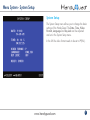
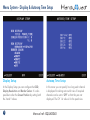
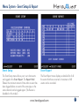
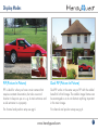
1
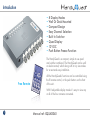
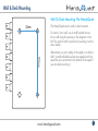
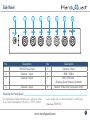
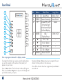
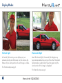
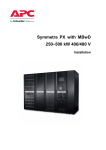
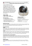
QUAD040 Useful compact quad unit that can be wall mounted or desk mounted. Multiple display options make it indispensable to the professional CCTV engineer. Handbook & Instructions 4 Camera Inputs with 8 display options (see pg 14-17) ...and more! Quad Pic In Pic H Split V Split XQUAD040 Introduction • • • • • • • • 8 Display Modes Wall Or Desk Mounted Compact Design Easy Channel Selection Built In Switcher Quad Display 12V DC Push Button Freeze Function The HandyQuad is a compact, simple to use quad and switcher combined. The HandyQuad can be wall or desk mounted, which along with its tiny size makes for a neat and easy installation. Free Remote All the HandyQuad’s functions can be controlled using the IR remote control, or the push buttons on the front of the unit. With 8 adjustable display modes it’s easy to view any or all of the four cameras connected. 2 Manual ref: XQUAD040 Wall & Desk Mounting Wall Or Desk Mounting The HandyQuad The HandyQuad can be wall or desk mounted. 52mm To mount it on a wall, use 4 small headed screws into a wall using the spacing in the diagram on the left. The quad is held in position by lowering it on the screw heads. 97mm Alternatively you can simply sit the quad on a desk or shelf. 4 small self-adhesive feet are supplied with the quad that you can attach to the bottom of the quad if you are desk mounting it. www.handyquad.com 3 Wiring Of The Quad DVR input is routed to “Monitor Output” by pressing the ‘DVR’ button on the HandyQuad, or the ‘PB’ button on the remote. DC 12V/1A CAM1 CAM2 CAM3 CAM4 DVR IN DVR OUT MONITOR OUT Just connect the 4 camera inputs to the BNC connectors labelled “CAM1-4”. The monitor simply connects to the BNC output labelled “Monitor out”. 12V Input 8 User definable display options (pic in pic, split screen etc) Camera 1 Camera 2 Camera 3 Permanent quad display Camera 4 4 The HandyQuad is really simple to wire up. Manual ref: XQUAD040 The “DVR In” connection is routed to “Monitor Output” by pressing the “DVR” button on the HandyQuad or the “PB” button on the remote. The “DVR Out” is a permanent quad display. This can be connected to a single channel on a DVR, alternatively it can be connected to a second monitor. Side Panel 1 2 CAM1 12V DC 3 4 5 6 7 8 CAM2 CAM3 CAM4 DVR IN DVR OUT MONITOR OUT No. 1 2 3 Description 12V DC Power Input Camera 1 Input Camera 2 Input No. 5 6 7 4 Camera 3 Input 8 Description Camera 4 Input DVR / VCR In DVR / VCR Out Displays Quad Screen Constantly Monitor Video Out (Composite Only) Powering the HandyQuad Our high quality, reliable AntiHum power supplies are ideal for use with the HandyQuad. We offer a 12V DC, 500mA power supply with an industry standard 2.1mm DC plug. Order Code: POW150 www.handyquad.com 5 Front Panel 1 2 3 POWER ESC 4 5 No. 1 2 3 Button ESC FREEZE PIP 4 ENTER 5 6 7 8 9 POWER MENU FREEZE AUTO PIP ZOOM ENTER DVR 6 7 8 9 Short Press Quad View Freeze Camera(s) 1x Dual PIP, 2x PIP 3x Vertical Split 4x Horizontal Split 5x Dual Display OK / Display Setup Ch 1 / Up Ch 2 / Down Ch 3 / Left Ch 4 / Right Power On/Off Long Press Menu / Exit Auto Switch Zoom DVR / VCR - How to program channels in display modes To program the channel you require, press the display mode you wish to program (on the remote or front panel) so it appears on your screen. Press the Enter button. The first channel number will begin to flash. Use the Left and Right arrow keys to scroll through until you find the channel you require. 6 Next press the Up or Down arrow keys to program the next channel or frame position in the same way. Once all the channels have been programmed press Enter to save and exit. Manual ref: XQUAD040 IR Remote Control Button MENU FRZ MENU PB ENTER ZOOM FRZ PB 1 A 2 B 3 AUTO 4 REMOTE CONTROL Function Button Menu / Exit ZOOM Freeze Current Image / ENTER 2x Unfreeze Up Left Display DVR / VCR Image / 2x Exit N/A Function Zoom / 2x Exit Zoom OK Down Right Quad View Start Auto-Switch N/A Dual PIP PIP Ch 1 Full screen 1x Vertical Split 2x Horizontal Split 3x Dual Display Ch 2 Full screen Ch 3 Full screen Ch 4 Full screen See opposite for setting channels in PIP, Dual PIP, Vertical Split, Horizontal Split and Dual Display. www.handyquad.com 7 Menu System - Main Menu Main Menu The HandyQuad has a really simple and easy to use menu system. Pressing Menu on the IR remote control, or holding ESC on the HandyQuad’s front panel will display the Main Menu. From here the Up and Down arrows are used to select the option/field required. The Left and Right arrows are used to change values and Enter is used to confirm selection. Pressing Menu whilst in the menu system will go back one screen. Pressing the Menu button whilst the Main Menu is displayed exits the menu system. 8 Manual ref: XQUAD040 Menu System - System Setup System Setup The System Setup menu allows you to change the basic settings of the HandyQuad. The Date, Time, Video Format, Language and Key Lock can be adjusted and set in the System Setup menu. In the UK the video format needs to be set to P (PAL). www.handyquad.com 9 Menu System - Display & Autoseq Time Setup Display Setup Autoseq Time Setup In the Display Setup you can configure the OSD, Display Resolution and Border Colour. It is also possible to alter the Screen Position by setting both the X and Y values. In this menu you can specify how long each channel is displayed for during auto switch view. If required channels can be set to ‘OFF’ so that they are not displayed. The CH 1-4 value is for the quad view. 10 Manual ref: XQUAD040 Menu System - Channel Setup Channel Setup In Channel Setup you can configure each channel separately to get the best image possible. You are able to set the channel Title (Max 4 characters), Brightness, Contrast, Saturation, Hue and Sharpness. You also have the option to Mirror the image either vertically or horizontally. www.handyquad.com 11 Menu System - Motion Setup Motion Setup In this menu you can configure Motion Detection for each channel. You can set the period of time you require Motion Detection to be enabled. Alternatively you can choose ‘Always On’ for constant detection. The Sensitivity, Velocity and Masking Area can also be set. (Once masking area has been set, move the cursor to the top of the frame to exit) The Sensitivity value can be set form -7 (Min) to +7 (Max). The higher the sensitivity value the more sensitive the HandyQuad is to slight movements. The Velocity value determines how sensitive the HandyQuad is to speed. If the velocity value is set low such as -6 or Min, slow moving objects will not be detected. 12 Manual ref: XQUAD040 Menu System - Event Setup & Report Event Setup Event Report The Event Setup menu allows you to set what events are logged in the Event Report. The Report Hold Time is the minimum amount of time after an event has been logged before an event of the same type on the same channel can be logged again. (The Buzzer is disabled on this model.) The Event Report menu displays a detailed list of all the events that have occurred. A maximum of 60 events can be recorded. www.handyquad.com 13 Display Modes Full Screen Quad Each channel can be displayed full screen by pressing the corresponding button on the remote, or on the front of the HandyQuad unit. This makes it easy to quickly switch between camera inputs. Quad view is a great way to display all four images at once ensuring nothing is missed. 14 Manual ref: XQUAD040 Display Modes PIP (Picture In Picture) Dual PIP (Picture In Picture) PIP is ideal for when you have a main camera that requires constant observation, but also a second location to keep an eye on. e.g. A main entrance and a side entrance to a property. Dual PIP works in the same way as PIP with the added benefit of a third image. The smaller image frames can be rearranged so as to not obstruct anything important in the main image. For channel and position setup see pg 6. For channel and position setup see pg 6. www.handyquad.com 15 Display Modes Vertical Split Horizontal Split In Vertical Split mode you can display any two cameras side by side full screen. As this narrows the frame only the centre portion of each image is visible. Much like Vertical Split, Horizontal Split displays any two cameras stacked one on top of the other. Horizontal Split provides a wider field of view but again only the centre section of the image is displayed. For channel setup see pg 6. 16 For channel setup see pg 6. Manual ref: XQUAD040 Display Modes Dual Display Auto Switching A great way to view two cameras at the same time. The full image of both cameras is displayed. Auto switch constantly cycles through all four camera inputs and the quad display. The amount of time each channel is displayed can be adjusted. Each camera can be turned off if not required during auto switch. For channel setup see pg 6. www.handyquad.com 17 Other Products To Consider - CAM220 Dome Camera • Auto Digital Zoom • Dual Voltage 12V DC, 24V AC • Built in Balun • Pelco D - (RS485 2 wire) • Pelco C - (Up the co-ax) • 700TVL colour mode - 800TVL B&W mode • NiteDevil low light – 0.00019Lux • Internal connections – no flying lead • Vandal-proof & Weatherproof • 3 Axis Gimbal for wall or ceiling mounting • Mega-pixel 2.8 ~ 12 mm Auto Iris Lens Maximum IR Sensitivity • Metal housing with Polycarbonate dome With a built in Balun the CAM220 can be installed with either CAT5 or Composite co-ax cable allowing flexible installation options. The camera’s menu can be controlled by “up the co-ax telemetry” (PELCO-C) or additional 2-wire telemetry (PELCO-D) making it easier to set up on site and remotely. Dual power (12V DC and 24V AC), a clever internal connection PCB for neat and fast installation and stunning picture quality make the CAM220 a great first choice CCTV Dome camera for any installation. 18 Order Code: CAM220 Find out more at www.nitedevil.com Other Products To Consider - CAM220 Dome Camera 1 Zoom Adjustment 3 Unlocking this screw allows you to adjust the zoom in and out of the camera. 2 Tilt Axis Unlock this screw and one on the other side to tilt the camera up and down. Focus Adjustment 4 7 Rotational Axis Turn this to rotate the cameras output image so that it is correct on a monitor. Unlocking this screw allows you to re-adjust the focus of the camera after adjusting the zoom. (Loosen tilt screws first) 5 Video Out - Main Unlock these screws to adjust the left-right orientation of the camera. Connect your co-ax to this for the main Video output. 8 (2 Screws, 1 either side) 6 Video Out - Spare Connection Block Spring lock connections to wire up the camera. Spare video out for local test using a test monitor. 9 Left-Right Axis Joystick 10 Press down to bring up the OSD then navigate using the joystick. Down again is select. Conduit Entry 20mm blank supplied. (Cable entry also at rear through a grommet) Find out more at www.nitedevil.com 19 Other Products To Consider - AlienDVR 10 Reasons the DVR is great value for money alienHero 16ch 1. 2. 3. 4. 5. 6. 7. 8. 9. 10. 20 Order Codes Built-in Video Analytics (finds evidence instantly!) 4ch 1TB: ALIEN654K True Realtime D1 Recording (even on the 16ch ) 8ch 1TB: ALIEN658K High Definition HDMI Output (along with VGA & BNC) 16ch 2TB:ALIEN666N Easy to Use Interface (said to be best in class) AutoPort Plug-and-Play (for easy internet setup) Compact Space Saving Case (slim modern design) Free Dynamic DNS Setup (saves you time) Full Alarm Inputs (16 on the 16 way) - (triggered how you want) Bespoke Software Available (you want it, we write it) Video Tagging (tag recording with keywords such as “theft”) Find out more at www.aliendvr.com Other Products To Consider - CCTV Mule Sends 4 video signals down 1 co-ax The CCTV Mule makes it easy to add extra cameras to existing installations, you save installation time and reduce the cost of buying and installing more cable. The Mules work in pairs. One Mule combines the video signals to transmit them down 1 single co-ax, the other Mule then reconstructs the individual video signals at the remote end. A low-cost, easy solution that offers huge installation benefits and opportunities to add extra cameras. 4x e Vid oI n & udio Ev e n a The clever electronics of the CCTV Mule also allow it to carry audio and RS485 data along the same co-ax cable. You can even carry three video signals in one direction and a fourth signal in the other direction! 1 ta da x O RG UT 59 Order Code: Order Code: Mule 4 - TX Specification Mule 4 - RX V1 12V DC 12V DC V2 V3 V4 DVR V1 V2 V3 V4 MULE004 (4-Way Pair) MULE002 (2-Way Pair) V1, V2, V3 & V4 in this direction Find out more at www.cctvmule.com Voltage - 12V DC, Tx 200mA, Rx 350mA Video inputs - 4, outputs - 1 Tx Video inputs - 1, outputs - 4 Rx Video quality - D1 @ 25fps - Every Camera Gain control for different cable lengths Operation modes - 5 types Cable required - RG59 or better Max Cable length - 200mtrs Size - 175 x 110 x 30mm 21 Other Products To Consider - VoiceOff Programmable Audio Alarm Unit RS232 inpu triggers up t 9999 sound to s!! • Trigger Up To 9999 Sounds • 20 Alarm Inputs Trigger, 20 Recordable Warnings • Removable SD Card • Talkback Function • RS232 Connection • Weatherproof • Activate Remotely Over The Internet • Additional Sound Files Can Be Downloaded at www.voiceoff.com The VoiceOff MK2 is an alarm activated voice or sound warning unit that has 20 separate alarm inputs, to trigger up to 20 different recorded sound files. With the new added feature of an RS232 input you can trigger up to 9999 sounds! 20 ala trigger rm inputs record 20 user able w arnings ! 22 Warning messages can be downloaded or recorded in MP3 format and stored on the removable SD card. These sounds can be used to welcome visitors, deter intruders, warn or inform people as they enter certain areas. Order Code: VOX200 Find out more at www.videomitter.com Other Products To Consider - Useful Tools CCTV Test Monitor BNC Ratchet Crimp • Easy PTZ Testing • Up to 6 Hours Battery Life • Monitor Output Testing • Check Video Signal Strength • Cable Continuity Checker • DC/AC Voltage Tester • Wrist/Neck Strap • Built-in Speaker Includes Crimps - 2pc 3pc Mini 3pc 248 Order Code: Order Code: LCD350 For more information visit www.cctvmate.com TOO980 Learn how to crimp a BNC! See online tip 248 More online tips at www.systemq.com 23 Specification Controls Freeze Frame Display Modes Power Input Current consumption PSU IR Remote Control Video In Video Inputs Video Out Video Outputs Dimensions Push Button Yes 8 12V DC - 2.1mm Plug 270mA Min 500mA PSU Required Supplied BNC 5 (4x Video, 1x DVR/VCR) BNC 2 (1x Monitor, 1x DVR/VCR) 149 x 124 x 28mm All specifications are approximate. System Q Ltd reserves the right to change any product specifications or features without notice. Whilst every effort is made to ensure that these instructions are complete and accurate, System Q Ltd cannot be held responsible in any way for any losses, no matter how they arise, from errors or omissions in these instructions, or the performance or non-performance of the equipment that these instructions refer to. WEE/CG0783SS 24 This symbol on the products and/or accompanying documents means that used electronic equipment must not be mixed with general household waste. For treatment, recovery and recycling please return this unit to your trade supplier or local designated collection point as defined by your local council. © Copyright System Q Ltd 2013