1
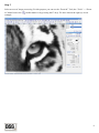
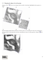
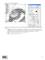
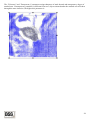
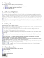
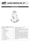
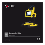
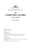
USER MANUAL
CONTENT
INTRODUCTION ................................................................................................................................................ 3
1
BASIC CONCEPTS .................................................................................................................................. 3
2
QUICK START ......................................................................................................................................... 7
2.1
3
4
Creating an element of a black-and white line drawing ............................................................ 7
DRAWING STROKES ........................................................................................................................... 15
3.1
Creating a group of strokes ........................................................................................................ 15
3.2
Drawing individual strokes......................................................................................................... 15
3.3
Changing the shape of a strokes group ...................................................................................... 16
PARAMETERS OF STROKES, THE “STROKES” TOOLBAR ...................................................... 17
4.1
Filtering loaded image................................................................................................................. 17
4.2
Rendering strokes........................................................................................................................ 18
4.3
Parameters of curve .................................................................................................................... 18
4.4
Dashed line parameters............................................................................................................... 24
4.5
Controlling thickness .................................................................................................................. 24
5
LAYERS, “OBJECTS” TOOLBAR...................................................................................................... 25
6
MASKS..................................................................................................................................................... 26
7
VIEW MODES ........................................................................................................................................ 29
8
TOOLS FOR CREATING STROKES ................................................................................................. 29
9
EDITING TOOLS ................................................................................................................................... 29
10
CLIPBOARD OPERATIONS................................................................................................................ 29
11
FILE OPERATIONS .............................................................................................................................. 30
12
SETTINGS AND HOTKEYS................................................................................................................. 31
12.1 Basic application parameters which may be set on the "Configure" toolbar .......................... 31
12.2 Hotkeys ............................................................................................................................................ 32
2
Introduction
The “BSS Strokes Maker” software is intended to create black-and-white and color stroke vector images on
basis of a source raster image. The program allows creating analogues of etchings and gravures in
semiautomatic mode, enabling the painter to use tools for automatic filling of stroke areas, as well as tools for
manual drawing of stroke line with subsequent automatic calculation of strokes.
1
Basic concepts
The basic element of the software is Strokes . This element contains one or several strokes, calculated by the
same parameters with regard to a source loadable image, for example: line type, inclination angle, dashed line
and thickness parameters. As well as by source image filtration mode, if a color image is used.
This version of the software has the following basic types of strokes:
•
Linear – strokes are assigned by straight line and parameters, applicable to straight line (inclination
angle, interval).
•
Sigmoid – strokes are assigned by wavy line (Sigmoid) and parameters, applicable to sigmoid line
(period, amplitude, inclination angle, and interval).
3
•
Concentric – strokes are assigned by circle lines and parameters, applicable to circle (center
coordinates, interval).
•
Radial – strokes are assigned by lines coming from circle center (center coordinates, interval, and initial
radius).
4
•
Template – strokes are assigned by free shape lines, given in a template. You can draw a template in
the application directly or load it from an external vector file.
•
Free curves – those drawn directly by hand basing on an image.
5
The next concept is Group of strokes . This element combines one or several strokes. For instance, one
group may combine linear and sigmoid strokes.
This software version defines 2 groups of strokes:
•
•
Convertible form changes type of strokes according to the shape of envelope line (FreeMeshtype).
Group of free curves includes strokes consisting of arbitrarily assigned curves.
The last (third) element is Layer . Layers combine groups of strokes and assign form and parameters of Masks.
Masks assigned in a layer are active for all groups of strokes, contained in this layer, and they determine
drawing areas.
Summary: Strokes contain stroke lines. Groups of strokes contain strokes and can assign form and position of
strokes. Layers contain groups and can assign masks to calculate the result.
Source raster image is used to calculate vector strokes. Both gray-scale black-and-white and color pictures can
be used. In the latter case, the application provides possibility to calculate strokes separately for each channel of
RGB and CMYK models.
6
2
Quick Start
2.1 Creating an element of a black-and white line drawing
Step 1
Start the EngravingsTools application.
Step 2
Load the test image. For this purpose select the menu item “File”-> “Open Image” or press the quick access
button
. Select the file “\Examples\TigerGS.tif” in the opened dialog box from the directory of the
EngravingsTools application examples and press OK. As a result, the selected image will be loaded into the
work area of the application.
7
Step 3
Select an area of image processing. For this purpose you can use the “Zoom In” Tool (the “Tools” -> “Zoom
in” Menu Item or the
example.
, toolbar button or by pressing the F2 key). We have chosen the right eye in our
8
Step 4
Select a tool for creating a strokes group (the “Tools” toolbar -> “Strokes Tool” or the
). Use this tool like a
tool for drawing a rectangle in any graphics editor. I.e., press the right mouse button and without releasing it
move the mouse until the desired area is highlighted, then release the right mouse button. As a result, a layer
with a rectangular area filled by strokes will be created. The area will be highlighted .
9
Step 5
Change Strokes Parameters . For this purpose use the “Strokes” toolbar (A detailed description of the Strokes
Parameters is given in “Strokes Parameters, “Strokes” toolbar” item). By default, it is situated at the right-hand
edge of screen. If you have accidentally closed the toolbar, you can open it again using the “Windows” ->
“Strokes” menu item.
Make sure, that the group of strokes is highlighted, and if the highlighting is lost, use the “Pick”
Tool for
highlighting. Change the angle of the current strokes by 60 degrees. Insert the value 60 into the “ Angle ” field .
To render the current strokes press the keyboard spacebar or use the “Render” -> “Render Current Strokes”
menu item, or the “Strokes”
toolbar button, or the similar button of the primary window toolbar.
10
Step 6
Add strokes with other parameters to the current group. For example, select the Sigmoid type of line and the
value of strokes angle equal to 15 degrees.
Then press the
. As a result new strokes will be added to the group.
You can see the listing of all strokes sets within the currently selected group in the list on the same “Strokes”
toolbar.
You can change parameters of any strokes selected in this list.
11
Step 7
Reduce the break of lines on white color for linear strokes. For this purpose select the linear strokes in the list
(as shown above). Then, change the position of the slider towards the line and press blank (or use other
indicated above options for rendering the current strokes).
As a result, the size of the break on the image white color will be reduced and the length of the current strokes
lines will be enlarged correspondingly.
12
Step 8
To view the result, disable the viewing of background image (the “View” menu -> “Show Source” or the
button ). ). Disable the viewing of contours (the “View” menu -> “Show Bounds” or the
button).
Step 9
To change the shape of a group of strokes use the “Shaper” Tool (the “Tools” menu -> “Shape Tool” or the
button ). After these changes are done, render the contents of the group completely, for which purpose press
the
button of the “Strokes” toolbar or select the corresponding item of the “Strokes” menu.
13
Step 10
Use the “Mask” -> “Free curve” or “Rectangle form” Tool (the “Mask” menu -> “Free curve”/ “Rectangle
form” or the
). buttons) for areas of strokes inclusion or exclusion. After these changes are done, render
the contents of the group completely, for which purpose press the
the corresponding item of the “Strokes” menu.
button of the “Strokes” toolbar or select
Step 11
Export the obtained result to Adobe Illustrator (*.AI) format for subsequent use. For this purpose make use of
the “Files” -> “Export” menu item or the
button on the toolbar.
14
3
Drawing Strokes
3.1 Creating a group of strokes
To draw a group of strokes the “Strokes Tool” is used (the “Tools” toolbar -> “Strokes Tool” or the
button
on the toolbar. Use this Tool like a tool for drawing a rectangle in any graphics editor. I.e., press the right
button of the mouse and without releasing it move the mouse until the desired area is highlighted, then release
the right button of the mouse. As a result, a layer with a rectangular area filled by strokes will be created. When
generating strokes, current parameters, assigned on the “Strokes” toolbar, are used. You can change the shape
of the created group, as required.
3.2 Drawing individual strokes
If it is necessary to draw several individual strokes, you can use the “Pen free curve”
Tool. This Tool draws
a continuous line, when the right button of the mouse is pressed. Upon completion of drawing, strokes
according to the shape of the drawn line and to the current parameters, assigned on the “Strokes” toolbar, are
created. At every subsequent drawing of a new line, the line will be inserted into the currently highlighted
strokes group. If there is no current highlighting, a new layer with a new strokes group will be created.
15
3.3 Changing the shape of a strokes group
Using the “Pick”
group.
Tool you can change position, modify size and rotate highlighted strokes groups or a
Besides changing standard linear parameters of strokes groups, you can change the shape of the setting line by
altering positions of individual nodes of the line and adding new nodes. For this purpose the “Shaper”
is used.
Tool
16
4
Parameters of Strokes, the “Strokes” Toolbar
You can use the “Strokes” toolbar to assign all parameters necessary for composing a line drawing.
4.1 Filtering loaded image
When using source color image, the parameters controlling RGB and CMYK channels are represented on the
toolbar. I.e., it is possible to plot strokes for each channel separately or in a set of selected ones. These
parameters are represented in the bottom part of the "Strokes" toolbar.
The drop-down list makes it possible to select a model of image representation. The three checkboxes on the
left enable the user to select Red, Green and Blue channels to be used for a RGB model, and Cyan-MagentaYellow-Black ones for a CMYK model, correspondingly. INV determines layer inversion.
Every set of strokes may have its own parameters of filtration. For example, one linear set of strokes in a group
may be rendered for Red value, an other sigmoid set may be rendered for Blue value, etc.
17
4.2 Rendering strokes
The following commands are used to process sets of strokes:
•
- renders strokes in the current streaking
•
- adds strokes to the currently selected group
•
- inserts strokes above the current strokes
•
- inserts strokes under the current strokes
•
- clears the current strokes
•
•
- renders all strokes in the current strokes group
- renders strokes in all selected groups
•
- clears strokes from all selected groups
•
- loads previously saved strokes into the currently selected group
•
- saves strokes of the currently selected group
The commands are accessible on the "Strokes" toolbar, the application toolbox, and in the "Rendering" menu.
4.3 Parameters of curve
Basic parameters of curve, according to which all strokes are further composed, are as follows:
• Type - assigns line shape. Different line types, including Linear, Sigmoid, Concentric, etc., are
determined by their parameters, and depending on selected type are loaded into the "Line" toolbar.
• Color - assigns the method of specifying line color. 4 options are available: Black, White, Palette and
Automatic.
- The first two options assign 2 line colors, i.e. black and white, correspondingly.
- “Palette” – this option enables the user to choose a line color from the color palette.
- “Automatic” – the color of a stroke is computed automatically depending on the average color of the image in
the area of the stroke and settings of the image filter, when processing a color picture (RGB or CMYK
channels).
•
Break – specifies the area of line break. The drop-down list assigns a break on light or dark area of an
image.
18
•
The slider
be broken.
assigns a threshold of color intensity, exceeding which the line will
The example below shows breaks under different values of these parameters:
Break on light:
19
Break on dark :
•
•
•
Min. length [mm] – this parameter assigns the minimum value of stroke length. Strokes having
length less than this parameter don't get in work area of the application.
Angle – assigns the angle of strokes.
Interval – assigns the interval between strokes.
20
Parameters for “Sigmoid” type line
Besides the mentioned above parameters, the following parameters are assigned for “Sigmoid” type line
as well:
• Amp.b/en – two values for the amplitude (wave height) of curve. The first value specifies the
height of the first curve, and the second one, of the last, respectively. The two parameters make
it possible to obtain a smooth transition from straight line to sigmoid line, as required.
• Bends – the number of bends (waves, or curve period).
• Disp – horizontal displacement of curve.
21
Parameters for “Concentric” type line
The following parameters are specified for concentric type lines:
• X0, Y0 – center coordinates. Changing these parameters you can displace circles inside a group.
22
Parameters for “Template” type lines (from a template)
This type of line enables you to assign manually a line shape and subsequently to fill a group with it according
to assigned parameters:
• Scale – increases a template in a group
• Rows/Cols – the number of rows and columns when multiplying a template
• [%] – overlap of rows and columns during multiplication.
• “Get curves” button – pressing this button opens a window, in which you can draw your curves
for a template or just export them from *.AI format.
23
4.4 Dashed line parameters
To control dashed lines, the following parameters are used:
•
- specifies the area of dashed line drawing. Two options are available:
Dashed line on light and Dashed line on dark . Therewith, dashed line will be drawn on light or dark
area of an image, correspondingly.
•
The Slider
- specifies a threshold value of the limit between continuous line
and dashed line.
Stroke length – specifies the minimum and the maximum length of a dashed line stroke.
Blank length (min./max.) – specifies the minimum and the maximum length of the blank between
dashed lines.
•
•
4.5 Controlling thickness
The following parameters are used to control thickness:
•
•
•
•
•
•
•
The drop-down list
- under the first value, the thickness increases on a
darker tone, while under the second, to the contrary, on a lighter tone.
Loss in break – line thickness in break decreases up to zero.
Loss on ends – independently on break, line thickness on ends falls to zero.
Multiplier – thickening factor. Increasing this parameter enlarges line thickness.
Base thickness – the minimum line thickness.
Smoothness – assigns smoothness of line thickness. The higher this parameter, the smoother drops of
line thickness.
Points of loss – the number of points on line ends, at which this loss occurs.
24
5
Layers, “Objects” Toolbar
The “Objects” toolbar represents structure of a project.
Using this toolbar you can displace layers and strokes in groups relative to each other (
highlight objects and remove them.
buttons),
You can displace objects between layers, using Drag and Drop operation as well.
25
6
Masks
Masks are intended to assign area of strokes generation. Masks are assigned for a layer, which means one set of
masks in a layer will be effective for all strokes belonging to this layer.
Two tools are available to draw masks:
•
- drawing a free shaped mask.
•
- drawing a rectangular mask
Two modes are accessible for masks on a plane:
- standard, objects will be represented within a limited area.
and
inverse mode – a limited area will not contain any objects.
26
Transparency mode for layers lying under a masked layer is also available:
- the masked area is transparent for all layers.
- the masked area is not transparent for underlying layers.
27
The “Tolerance” and “Transparency” parameters assign sharpness of mask bounds and transparency degree of
masked area. If transparency parameter is different from zero, objects situated under the masked area will show
through the more intensive, the higher this parameter is.
28
7
View modes
The application provides 3 options for viewing work area:
8
•
- area bounds, masks, source image and result are seen.
•
- area bounds, masks and result are seen.
•
- result is only seen.
Tools for creating strokes
Two Tools are intended for creating strokes: –
- creating a deformable group of strokes. Use this Tool like a tool for drawing a rectangle in any graphics
editor. I.e., press the right button of the mouse and without releasing it move the mouse until the desired area is
highlighted, and then release the right mouse button. As a result, a layer with a rectangular area filled by strokes
will be created. The area will be highlighted. The parameters of strokes will be indicated on the “Strokes Tool”
toolbar.
- is a Tool for creating strokes manually. It allows drawing strokes by hand. At that, every newly drawn line
will be added to the current highlighted strokes group. To create a new one, it is necessary to cancel the current
highlighting.
9
Editing tools
Standard tools are used for editing operations:
— the “Select Objects” Tool is intended to highlight and manipulate objects (masks, included and excluded
areas). It is similar to the “Tools/Pick” menu item.
— the “Select Nodes” Tool is intended to edit curves. It is similar to the “Tools / Shaper” menu item.
— the “Metric” Tool is intended for different measurements.
— the “Zoom In” Tool allows magnifying a screen image twice. It is similar to the “Tools / Zoom / Zoom
In” menu item.
— the “Zoom Out” Tool allows reducing a screen image twice. It is similar to the “Tools / Zoom / Zoom
Out” menu item .
— the “All Objects” Tool allows enlarging or reducing a screen image according to the size of work
window. It is similar to the “Tools / Zoom / All Objects” menu item.
— the “Selected” Tool allows enlarging or reducing a selected area of a screen image according to the size
of work window. It is similar to the “Tools / Zoom / Selected” menu item .
— the “Zoom” form allows scaling a screen image, choosing a percentage value of source image in the
drop-down list or by inserting a necessary value manually .
— using the “Area View” form you can denominate selected parts of traceable image to
navigate between them later on.
10
Clipboard operations
- copy an object to clipboard and delete from work area
- copy to clipboard
- copy from clipboard
- duplicate an object
- delete a highlighted object
29
11
File operations
To work with files, the following basic operations are accessible:
- create a new project
- open an already existing project
- add objects to an existing project
- save a work project
- open a source image
- export result in Adobe Illustrator format as wireframes with filling.
- export result in Adobe Illustrator format as parts of lines with thickness.
30
12
Settings and hotkeys
12.1 Basic application parameters which may be set on the "Configure" toolbar
The toolbar of preferred settings for measurement units, marking colors and optimization parameters.
The "General" Tab
“Optimization” – assigns parameters for optimization of curves during exportation:
• “Precision” -determines relative precision of result. The lower this parameter, the closer optimized
curve will be to source curve, but the number of nodes will be, respectively, larger. The default value is
0.1.
• “Density” - determines step for curve fitting during optimization. I.e., 10 segments of straight line are
usually enough to draw a portion of Bezier curve, that corresponds to the value of this parameter equal
to 1. But sometimes it is necessary to increase the interval between nodes at the expense of minor loss of
quality, and then this parameter may be increased. Or it may be decreased to improve result quality, but
that is required on very rare occasions.
“Metrics” - allows setting preferable measurement units (pixels, inches or millimeters).
“Directories” - enables you to assign your own catalogue for temporary files.
“Pen Hit Spot” -specifies the size of point of hitting on another line for tools used when drawing strokes and
masks by hand.
The "Controls" Tab is intended to assign hotkeys to commands and tools of the application.
Attention: The Software configuration, as well as definition of hotkeys are kept in Options.xml file. Before
changing settings make sure that Options.xml file has no Read-Only attribute selected. All changes in
configuration file are saved when closing the application.
31
12.2 Hotkeys
Hotkeys are key combinations to which the software can respond during operation. You can add new Hotkeys
and re-define existing ones in the "Configure" Toolbar (Windows menu / Configure), on the "Controls" Tab.
1. New — Ctrl+N
2. Open Project — Ctrl+O
3. Open Image — Ctrl+I
4. Save project — Ctrl+S
5. Export — Ctrl+E
6. Zoom In — F2
7. Zoom Out — F3
8. All Objects (Zoom) — F4
9. Selected (Zoom) — Shift+F2
10. Pick — Ctrl+Q
11. Shaper — Ctrl+A
12. Source Cleaner — Shift+1
13. Help — F1
14. Exit — Shift+Ctrl+E
15. Copy — Ctrl+C
16. Paste — Ctrl+V
17. Duplicate — Ctrl+D
18. Pen Line — 1
19. Pen Free Curve — 2
20. Include Prompts — 3
21. Exclude Prompts — 4
22. Filled Prompts — 5
23. Invert Mask — I
32