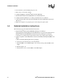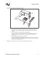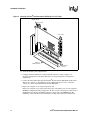
1
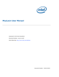
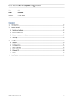
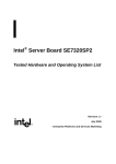
Intel® Raid Controller SRCS28X
User Manual
January 2005
Order Number: C89415-002
Contents
INFORMATION IN THIS DOCUMENT IS PROVIDED IN CONNECTION WITH INTEL® PRODUCTS. NO LICENSE, EXPRESS OR IMPLIED, BY
ESTOPPEL OR OTHERWISE, TO ANY INTELLECTUAL PROPERTY RIGHTS IS GRANTED BY THIS DOCUMENT. EXCEPT AS PROVIDED IN
INTEL'S TERMS AND CONDITIONS OF SALE FOR SUCH PRODUCTS, INTEL ASSUMES NO LIABILITY WHATSOEVER, AND INTEL DISCLAIMS
ANY EXPRESS OR IMPLIED WARRANTY, RELATING TO SALE AND/OR USE OF INTEL PRODUCTS INCLUDING LIABILITY OR WARRANTIES
RELATING TO FITNESS FOR A PARTICULAR PURPOSE, MERCHANTABILITY, OR INFRINGEMENT OF ANY PATENT, COPYRIGHT OR OTHER
INTELLECTUAL PROPERTY RIGHT. Intel products are not intended for use in medical, life saving, life sustaining applications.
Intel may make changes to specifications and product descriptions at any time, without notice.
Designers must not rely on the absence or characteristics of any features or instructions marked “reserved” or “undefined.” Intel reserves these for
future definition and shall have no responsibility whatsoever for conflicts or incompatibilities arising from future changes to them.
The Intel® Raid Controller SRCS28X may contain design defects or errors known as errata which may cause the product to deviate from published
specifications. Current characterized errata are available on request.
MPEG is an international standard for video compression/decompression promoted by ISO. Implementations of MPEG CODECs, or MPEG enabled
platforms may require licenses from various entities, including Intel Corporation.
This document and the software described in it are furnished under license and may only be used or copied in accordance with the terms of the
license. The information in this document is furnished for informational use only, is subject to change without notice, and should not be construed as a
commitment by Intel Corporation. Intel Corporation assumes no responsibility or liability for any errors or inaccuracies that may appear in this
document or any software that may be provided in association with this document. Except as permitted by such license, no part of this document may
be reproduced, stored in a retrieval system, or transmitted in any form or by any means without the express written consent of Intel Corporation.
Contact your local Intel sales office or your distributor to obtain the latest specifications and before placing your product order.
Copies of documents which have an ordering number and are referenced in this document, or other Intel literature may be obtained by calling
1-800-548-4725 or by visiting Intel's website at http://www.intel.com.
AlertVIEW, AnyPoint, AppChoice, BoardWatch, BunnyPeople, CablePort, Celeron, Chips, CT Connect, CT Media, Dialogic, DM3, EtherExpress,
ETOX, FlashFile, i386, i486, i960, iCOMP, InstantIP, Intel, Intel logo, Intel386, Intel486, Intel740, IntelDX2, IntelDX4, IntelSX2, Intel Create & Share,
Intel GigaBlade, Intel InBusiness, Intel Inside, Intel Inside logo, Intel NetBurst, Intel NetMerge, Intel NetStructure, Intel Play, Intel Play logo, Intel
SingleDriver, Intel SpeedStep, Intel StrataFlash, Intel TeamStation, Intel Xeon, Intel XScale, IPLink, Itanium, LANDesk, LanRover, MCS, MMX, MMX
logo, Optimizer logo, OverDrive, Paragon, PC Dads, PC Parents, PDCharm, Pentium, Pentium II Xeon, Pentium III Xeon, Performance at Your
Command, RemoteExpress, Shiva, SmartDie, Solutions960, Sound Mark, StorageExpress, The Computer Inside., The Journey Inside,
TokenExpress, Trillium, VoiceBrick, Vtune, and Xircom are trademarks or registered trademarks of Intel Corporation or its subsidiaries in the United
States and other countries.
*Other names and brands may be claimed as the property of others.
Copyright © Intel Corporation, 2005
2
Intel® Raid Controller SRCS28X User Manual
Contents
Electromagnetic Compatibility Notices
This device complies with Part 15 of the FCC Rules. Operation is subject to the following two conditions:
1. This device may not cause harmful interference, and
2. This device must accept any interference received, including interference that may cause undesired operation.
This equipment has been tested and found to comply with the limits for a Class B digital device, pursuant to part 15 of the FCC
Rules. These limits are designed to provide reasonable protection against harmful interference in a residential installation. This
equipment generates, uses, and can radiate radio frequency energy and, if not installed and used in accordance with the
instructions, may cause harmful interference to radio communications. However, there is no guarantee that interference will not
occur in a particular installation. If this equipment does cause harmful interference to radio or television reception, which can be
determined by turning the equipment off and on, the user is encouraged to try to correct the interference by one or more of the
following measures:
²
²
²
²
Reorient or relocate the receiving antenna.
Increase the separation between the equipment and the receiver.
Connect the equipment into an outlet on a circuit different from that to which the receiver is connected.
Consult the dealer or an experienced radio/TV technician for help.
Intel is not responsible for any radio or television interference caused by unauthorized modification of this equipment or the
substitution or attachment of connecting cables and equipment other than those specified by Intel. The correction of interferences
caused by such unauthorized modification, substitution, or attachment will be the responsibility of the user.
Intel RAID Controllers are tested to comply with FCC standards for home or office use.
This Class B digital apparatus meets all requirements of the Canadian Interference-Causing Equipment Regulations.
Cet appareil numérique de la classe B respecte toutes les exigences du Règlement sur le matériel brouilleur du Canada.
This is a Class B product based on the standard of the Voluntary Control Council for Interference from Information Technology
Equipment (VCCI). If this is used near a radio or television receiver in a domestic environment, it may cause radio interference.
Install and use the equipment according to the instruction manual.
Intel® Raid Controller SRCS28X User Manual
3
Contents
Contents
1
1.1
1.2
1.3
Preface ......................................................................................................................... 7
Organization ................................................................................................................................ 7
Related Publications .................................................................................................................... 7
1.2.1 Intel RAID Software User’s Guide .................................................................................. 7
Safety Instructions ....................................................................................................................... 7
1.3.1 When Using Your Computer System.............................................................................. 8
1.3.2 When Working Inside Your Computer ............................................................................ 8
1.3.3 Protecting Against Electrostatic Discharge..................................................................... 9
2
2.1
2.2
2.3
Introduction ................................................................................................................. 11
Overview..................................................................................................................................... 11
2.1.1 Adapter Description ....................................................................................................... 12
2.1.2 Enclosure Management................................................................................................. 12
2.1.3 Operating System Support ............................................................................................ 12
2.1.4 RAID Configuration Utilities ........................................................................................... 13
Features ..................................................................................................................................... 13
Intel® Raid Controller SRCS28X Specifications ......................................................................... 14
3
3.1
3.2
3.3
3.4
3.5
Hardware Installation .................................................................................................. 15
Installation Overview .................................................................................................................. 15
Requirements ............................................................................................................................. 15
Quick Installation Instructions ..................................................................................................... 15
Detailed Installation Instructions ................................................................................................. 16
After Installing the Intel® Raid Controller SRCS28X................................................................... 19
Intel® Raid Controller SRCS28X Characteristics........................................................ 21
4
4.1
4.2
Intel® Raid Controller SRCS28X Characteristics........................................................................ 21
4.1.1 Intel® Raid Controller SRCS28X Characteristics in Detail............................................. 21
Physical and Environmental Specifications ................................................................................ 23
4.2.1 Electrical Characteristics ............................................................................................... 23
4.2.2 Thermal and Atmospheric Characteristics..................................................................... 23
4.2.3 Safety Characteristics.................................................................................................... 24
A
Glossary of Terms ...................................................................................................... 25
Figures
1
2
3
4
Intel® Raid Controller SRCS28X Block Diagram ........................................................................ 11
Battery Backup Unit (BBU) Installation....................................................................................... 17
Inserting the Intel® Raid Controller SRCS28X in a PCI-X Slot ................................................... 18
Intel® Raid Controller SRCS28X Layout..................................................................................... 23
Tables
1
2
4
Intel® Raid Controller SRCS28X Characteristics........................................................................ 14
Intel® Raid Controller SRCS28X Characteristics........................................................................ 21
Intel® Raid Controller SRCS28X User Manual
Contents
3
4
5
Intel® Raid Controller SRCS28X Connector Information ............................................................22
Maximum Power Requirements..................................................................................................23
Glossary of Terms ......................................................................................................................25
Revision History
Date
Revision
October 2004
001
Intel® Raid Controller SRCS28X User Manual
Description
Initial release
5
Contents
6
Intel® Raid Controller SRCS28X User Manual
Preface
1
This document assumes that you have some familiarity with RAID controllers and related support
devices. The people who benefit from this book are:
• Anyone installing an Intel® Raid Controller SRCS28X storage adapter into a system
• Engineers who are designing an Intel® Raid Controller SRCS28X into a system
• Engineers and managers who are evaluating the Intel® Raid Controller SRCS28X storage
adapter for possible use in a system
1.1
Organization
Use this manual to install and configure your Intel® Raid Controller SRCS28X in the host system.
The information in this document is independent of the back-end bus that the system uses and
applies to both MegaRAID SCSI storage adapters and Serial ATA storage adapters.
This document has the following chapters and appendixes:
• Chapter 2, “Introduction”describes the Intel® Raid Controller SRCS28X.
• Chapter 3, “Hardware Installation”describes how to install an Intel® Raid Controller
SRCS28X in a system.
• Chapter 4, “Intel® Raid Controller SRCS28X Characteristics”provides the environmental and
electrical specifications for the Intel® Raid Controller SRCS28X. This chapter also provides
the mechanical drawing, jumper definitions, and connector locations for the Intel® Raid
Controller SRCS28X.
• Appendix A lists and explains terms and abbreviations that are used in this manual.
• Appendix B provides forms to send or fax to Intel if you encounter difficulty with your Intel®
Raid Controller SRCS28X.
1.2
Related Publications
1.2.1
Intel RAID Software User’s Guide
This document is on the resource CD included with the RAID Controller.
1.3
Safety Instructions
Use the following safety guidelines to help protect your computer system from potential damage
and to ensure your own personal safety.
Intel® Raid Controller SRCS28X User Manual
7
Preface
1.3.1
When Using Your Computer System
As you use your computer system, observe the following safety guidelines:
Caution:
Do not operate your computer system with any cover(s) (such as computer covers, bezels, filler
brackets, and front-panel inserts) removed:
• To help avoid damaging your computer, be sure the voltage selection switch on the power
supply is set to match the alternating current (AC) power available at your location:
— 115 volts (V)/60 hertz (Hz) in most of North and South America and some Far Eastern
countries such as Japan, South Korea, and Taiwan
— 230 V/50 Hz in most of Europe, the Middle East, and the Far East. Also be sure your
monitor and attached peripherals are electrically rated to operate with the AC power
available in your location.
• To help avoid possible damage to the system board, wait five seconds after turning off the
system before removing a component from the system board or disconnecting a peripheral
device from the computer.
• To help prevent electric shock, plug the computer and peripheral power cables into properly
grounded power sources. These cables are equipped with 3-prong plugs to ensure proper
grounding. Do not use adapter plugs or remove the grounding prong from a cable. If you must
use an extension cable, use a 3-wire cable with properly grounded plugs.
• To help protect your computer system from sudden, transient increases and decreases in
electrical power, use a surge suppressor, line conditioner, or uninterruptible power supply.
• Be sure nothing rests on your computer system’s cables and that the cables are not located
where they can be stepped on or tripped over.
• Do not spill food or liquids on your computer. If the computer gets wet, consult the
documentation that came with it.
• Do not push any objects into the openings of your computer. Doing so can cause fire or electric
shock by shorting out interior components.
• Keep your computer away from radiators and heat sources. Also, do not block cooling vents.
Avoid placing loose papers underneath your computer; do not place your computer in a closedin wall unit or on a rug.
1.3.2
When Working Inside Your Computer
Note:
Do not attempt to service the computer system yourself, except as explained in this guide and
elsewhere in Intel documentation. Always follow installation and service instructions closely.
1. Turn off your computer and any peripherals.
2. Disconnect your computer and peripherals from their power sources. Also disconnect any
telephone or telecommunications lines from the computer.
3. Doing so reduces the potential for personal injury or shock.
Also note these safety guidelines:
• When you disconnect a cable, pull on its connector or on its strain-relief loop, not on the cable
itself. Some cables have a connector with locking tabs; if you are disconnecting this type of
cable, press in on the locking tabs before disconnect the cable. As you pull connectors apart,
8
Intel® Raid Controller SRCS28X User Manual
Preface
keep them evenly aligned to avoid bending any connector pins. Also, before you connect a
cable, make sure both connectors are correctly oriented and aligned.
• Handle components and cards with care. Don’t touch the components or contacts on a card.
Hold a card by its edges or by its metal mounting bracket. Hold a component such as a
microprocessor chip by its edges, not by its pins.
1.3.3
Protecting Against Electrostatic Discharge
Static electricity can harm delicate components inside your computer. To prevent static damage,
discharge static electricity from your body before you touch any of your computer’s electronic
components, such as the microprocessor. You can do so by touching an unpainted metal surface,
such as the metal around the card-slot openings at the back of the computer.
As you continue to work inside the computer, periodically touch an unpainted metal surface to
remove any static charge your body may have accumulated. In addition to the preceding
precautions, you can also take the following steps to prevent damage from electrostatic discharge
(ESD):
• When unpacking a static-sensitive component from its shipping carton, do not remove the
component from the antistatic packing material until you are ready to install the component in
your computer. Just before unwrapping the antistatic packaging, be sure to discharge static
electricity from your body.
• When transporting a sensitive component, first place it in an antistatic container or packaging.
Handle all sensitive components in a static-safe area. If possible, use antistatic floor pads and
workbench pads.
Intel® Raid Controller SRCS28X User Manual
9
Preface
10
Intel® Raid Controller SRCS28X User Manual
Introduction
2
This chapter describes the Intel® Raid Controller SRCS28X and consists of the following sections:
• Section 2.1, “Overview” on page 11
• Section 2.2, “Features” on page 13
• Section 2.3, “Intel® Raid Controller SRCS28X Specifications” on page 14
2.1
Overview
The Intel® Raid Controller SRCS28X provides a high-performance intelligent PCI-X to Serial ATA
(Peripheral Component Interconnect-X to High Speed Serialized AT Attachment) interface with
RAID (Redundant Array of Independent Disks) control capabilities.
You can install the SATA board on a PCI-X bus and use it to connect Serial ATA drives to the host
computer over a Serial ATA cable.
The Intel® Raid Controller SRCS28X is an ideal RAID solution for the internal storage of
workgroup, departmental, and entry-level enterprise systems. It offers a cost-effective way to
implement RAID in a server.
Figure 1. Intel® Raid Controller SRCS28X Block Diagram
Intel® Raid Controller SRCS28X User Manual
11
Introduction
2.1.1
Adapter Description
The Intel® Raid Controller SRCS28X is a half-size storage adapter (6.875” x 4.2”) that provides
support for eight Serial ATA ports. You can attach a daughtercard to provide battery backup
support.
The Intel® Raid Controller SRCS28X uses an Intel 80331 I/O Processor to support the Serial ATA
ports. The Intel 80331 I/O Processor provides the intelligent RAID management capabilities. The
Intel® Raid Controller SRCS28X supports RAID 0, 1, 5, 10, and 50.
2.1.2
Enclosure Management
In addition, the Intel® Raid Controller SRCS28X offers enclosure management through the same
protocols used for SCSI Accessed Fault-Tolerant Enclosures (SAF-TE), using an I2C interface to
communicate with the storage enclosure processor (SEP). This feature allows you to use RAID
capabilities provided by the Intel® Raid Controller SRCS28X in an enclosure containing your hard
drives.
The Intel® Raid Controller SRCS28X uses the SAF-TE command protocol to communicate control
and status with the storage enclosure processor (SEP). The SAF-TE protocol defined in the SATA
II specification is used to communicate or perform SAF-TE operations such as setting the drive
state and turning off/on LED with the SEP device. SEP is a micro controller resides on SATA
backplane. It senses drive inserted status, drive activity and status LEDs near each hard drive slot.
The drive status is reported and LED control performed according to commands through I2C bus.
LEDs are located on the backplane near each hard drive slot.
2.1.3
Operating System Support
The Intel® Raid Controller SRCS28X supports several major operating systems. Intel provides
device drivers and RAID management tools for operating systems on the resource CD that
accompanies the Intel® Raid Controller SRCS28X.
In addition, you can download the latest drivers and software on the Intel support web site: http://
www.support.intel.com.
Refer to the Software User’s Guide on the Resource CD for instructions for installing the device
drivers. Be sure to use the latest Service Packs provided by the operating system manufacturer and
review the readme file that accompanies the driver.
The Intel® Raid Controller SRCS28X supports the following operating systems:
•
•
•
•
•
•
Note:
12
Microsoft* Windows* XP
Microsoft* Windows* 2000
Microsoft* Windows Server* 2003
Novell* NetWare*
Red Hat* Linux*, and
SuSE* Linux*
The operating systems supported by this controller may not be supported by your server board.
Please refer to the tested OS list for your server board at http://support.intel.com/support/
Intel® Raid Controller SRCS28X User Manual
Introduction
motherboards/server/. See also the tested hardware and operating system list for the Intel® Raid
Controller SRCS28X to make sure the RAID controller supports your operating system.
2.1.4
RAID Configuration Utilities
The Intel® Raid Controller SRCS28X provides several configuration utilities that you can use to
configure arrays and logical drives. The utilities are listed in Section 2.2, “Features” on page 13 in
this chapter.
For information on configuring RAID arrays and using the configuration and management tools,
refer to the Software User’s Guide.
2.2
Features
This section highlights the features of the Intel® Raid Controller SRCS28X. The Intel® Raid
Controller SRCS28X offers the following:
• Provides eight internal Serial ATA ports
• Support the Serial ATA, Revision 1.0, specification and Serial ATA II Extensions to Serial ATA
1.0:
— Provide a 150 Mbytes/s and 300 Mbytes/s bus speed
— Use a low-cost, small 7-pin connector with thin, flexible cables
— Use low-voltage signalling levels to reduce current draw, EM emission, and signal
switching time
— Support enclosure management, using an I2C interface to communicate with a storage
enclosure processor
• Support the PCI-X Specification, Version 1.0a:
— Provide up to 64-bit, 133 MHz data transfers from the host system to the Intel® Raid
Controller SRCS28X
— Are backward compatible with previous implementations of the PCI specification
— Conform to the half-size PCI form factor
• RAID 0, 1, 5, 10, and 50 I/O Processor:
— Use an Intel 80331 to provide intelligent RAID management
— Provide hardware-based exclusive-OR generation and checking
• Support RAID Management tools that enable the user to:
— Configure logical disks and physical arrays
— Fail physical disks and logical arrays
— Rebuild data from failed drives while the system is still operational
— Specify the rebuild rate
— Perform online RAID level migration
• Provide an optional battery backup via a daughter card with battery and power circuitry
Intel® Raid Controller SRCS28X User Manual
13
Introduction
2.3
Intel® Raid Controller SRCS28X Specifications
Table 1 summarizes the specifications of the Intel® Raid Controller SRCS28X.
Table 1.
Intel® Raid Controller SRCS28X Characteristics
Intel® Raid Controller SRCS28X
Feature
Number of Ports
8
Serial ATA Bus Speed
Serial ATA Data Transfer
1.5 Gbps and 3.0 Gbps
Rate1
150 MBps, 300 MBps
Intelligent RAID Management
Yes, using the Intel 80331 processor
PCI Bus Width and Speed
64-bit, 133 MHz
PCI Data Transfer
Ratea
RAID Levels
1064 MBps
0, 1, 5, 10, and 50
SDRAM Support
128 Mbytes ECC DDR 333 SDRAM
Cache Function
Write-back, Write-through, Adaptive Read Ahead,
Non-Read Ahead, Read Ahead, Cache I/O,
Direct I/O
Online Expansion
Yes
Hot Spare Pool
Yes
Hot Swap
Yes
Hardware Exclusive-OR
Yes
Enclosure Management Support
Yes
Optional BBU (sold separately)
Yes
a. Theoretical transfer rate
14
Intel® Raid Controller SRCS28X User Manual
Hardware Installation
3
This chapter describes the hardware installation of the Intel® Raid Controller SRCS28X. This
chapter consists of the following sections:
•
•
•
•
•
3.1
Section 3.1, “Installation Overview” on page 15
Section 3.2, “Requirements” on page 15
Section 3.3, “Quick Installation Instructions” on page 15
Section 3.4, “Detailed Installation Instructions” on page 16
Section 3.5, “After Installing the Intel® Raid Controller SRCS28X” on page 19
Installation Overview
The following steps provide an overview of the operations to install and configure the Intel® Raid
Controller SRCS28X for RAID operations.
1. Install the Hardware. Refer to Section 3.3, “Quick Installation Instructions” on page 15 or
Section 3.4, “Detailed Installation Instructions” on page 16 for hardware installation
instructions.
2. Configure the system BIOS. Refer to the system documentation for more information.
3. Run the setup utility to configure the Serial ATA drives into a RAID array. Refer to the Intel
Software Guide for RAID Products for more information.
4. Install the operating system driver. Refer to the Intel Software Guide for RAID Products for
more information.
5. Install and run the Intel® Raid Controller SRCS28X to manage the RAID system configuration
and performance. Refer to the Software User’s Guide for more information.
3.2
Requirements
You must have the following items to install and use a Intel® Raid Controller SRCS28X:
• An Intel® Raid Controller SRCS28X and device driver
• Host computer with an available PCI-X expansion slot
• Serial ATA disk drives and cables
3.3
Quick Installation Instructions
Follow these instructions to install your Intel® Raid Controller SRCS28X if you are comfortable
with the installation procedure.
1. Unpack the Intel® Raid Controller SRCS28X and inspect it for damage.
Intel® Raid Controller SRCS28X User Manual
15
Hardware Installation
2. Power down the system and unplug the power cord.
3. Remove the cover from the computer.
4. Configure the jumpers on the Intel® Raid Controller SRCS28X.
5. Insert the Intel® Raid Controller SRCS28X in an available PCI-X slot.
6. Configure the Serial ATA devices according to the instructions for each device.
7. Connect the Serial ATA cables between the Intel® Raid Controller SRCS28X and the Serial
ATA devices.
8. Replace the computer cover, plug the power cord in, and power up the system.
3.4
Detailed Installation Instructions
The following steps provide detailed installation instructions.
1. Unpack the Intel® Raid Controller SRCS28X and inspect it for damage.
Unpack and install the Intel® Raid Controller SRCS28X in a static-free environment. Remove
the Intel® Raid Controller SRCS28X from the anti-static bag and inspect it for damage.
Contact Intel or your Intel support representative if the storage adapter appears damaged.
2. (Optional, required to enable Write Back Cache) Attach the Battery Backup Unit (BBU) to the
adapter.
a. Remove the Battery Backup Unit from its packaging.
b. Connect the wire from the battery to the Circuit Board.
c. Position the BBU over the RAID adapter so the connectors line up. Press the BBU on the
adapter.
d. Turn the Adapter over.
e. Using the three screws, secure the BBU to the RAID Adapter.
16
Intel® Raid Controller SRCS28X User Manual
Hardware Installation
Figure 2. Battery Backup Unit (BBU) Installation
A
B
C
3. Power down the system.
Turn off the computer and physically remove the power cord from the back of the power
supply. Remove the cover from the computer chassis. Disconnect the system from any
networks.
4. Configure the jumpers on the Intel® Raid Controller SRCS28X.
Configure the jumper settings on the Intel® Raid Controller SRCS28X using the jumper
definitions and locations provided in Chapter 4, “Intel® Raid Controller SRCS28X
Characteristics.”
5. Carefully insert the Intel® Raid Controller SRCS28X.
Align the Intel® Raid Controller SRCS28X to a PCI-X slot. Press down gently but firmly to
properly seat the Intel® Raid Controller SRCS28X in the slot. Figure 3 shows how to insert the
Intel® Raid Controller SRCS28X in a slot.
Caution:
Do not apply pressure to the battery backup unit when installing the board.
Intel® Raid Controller SRCS28X User Manual
17
Hardware Installation
Figure 3. Inserting the Intel® Raid Controller SRCS28X in a PCI-X Slot
Bracket Screw
Press Here
Press Here
Edge of
Mother Board
64-bit Slots
(3.3 V)
6. Screw the bracket to the computer frame.
7. Configure the Serial ATA devices and install them in the host system computer case.
See the documentation for the Serial ATA device for any pre-installation configuration
requirements.
8. Connect the Serial ATA cables between the Intel® Raid Controller SRCS28X and the Serial
ATA devices. Chapter 4, “Intel® Raid Controller SRCS28X Characteristics,” shows the
connector locations on the Intel® Raid Controller SRCS28X.
9. Replace the computer cover and power up the system.
Replace the computer cover and reconnect the power cords. Turn power on to the computer.
The BIOS configuration utility prompt times out after several seconds. The second portion of
the BIOS message displays the number, firmware version and cache SDRAM size. The
numbering of the controller follows the PCI slot scanning order used by the motherboard.
18
Intel® Raid Controller SRCS28X User Manual
Hardware Installation
3.5
After Installing the Intel® Raid Controller SRCS28X
After you install the Intel® Raid Controller SRCS28X, you must install the device driver and define
the logical drives and physical disk arrays. Refer to the Software User’s Guide for detailed device
driver installation steps. Refer to it for detailed steps for configuring physical arrays and logical
drives.
Intel® Raid Controller SRCS28X User Manual
19
Hardware Installation
20
Intel® Raid Controller SRCS28X User Manual
Intel® Raid Controller SRCS28X
Characteristics
4
This chapter describes the characteristics of the Intel® Raid Controller SRCS28X. This chapter
includes these topics:
• Section 4.1, “Intel® Raid Controller SRCS28X Characteristics” on page 21
• Section 4.2, “Physical and Environmental Specifications” on page 23
4.1
Intel® Raid Controller SRCS28X Characteristics
The Intel® Raid Controller SRCS28X conforms to the PCI-X Local Bus Specification, Revision
1.0a and is backward compatible with previous revisions of the PCI specification. The Intel® Raid
Controller SRCS28X supports the Serial ATA Specification, version 1.0, and Serial ATA II
Extensions to Serial ATA 1.0, Revision 1.0.
Table 2 summarizes the characteristics of the Intel® Raid Controller SRCS28X.
Table 2.
Intel® Raid Controller SRCS28X Characteristics
Adapter
Intel® Raid
Controller
SRCS28X
Ports
8
RAID Levels
0, 1, 5, 10, and 50
PCI Bus Mode
64 bits, 133 MHz PCI-X
Board Dimensions
6.6 x 4.2 inches (168 ×
107 mm)
The following subsections provide detailed descriptions of the Intel® Raid Controller SRCS28X.
4.1.1
Intel® Raid Controller SRCS28X Characteristics in Detail
The Intel® Raid Controller SRCS28X is an intelligent RAID controller that provides eight Serial
ATA ports and support RAID 0, RAID 1, RAID 5, RAID 10, and RAID 50. The Intel® Raid
Controller SRCS28X does the following:
• Supports eight Serial ATA ports:
— Uses differential signalling
— Transfers data in frames
— Supports Serial ATA power management
• Are compliant with the PCI-X and PCI 2.3 Specifications
• Support up to a 64-bit/133 MHz PCI-X interface:
— Function in a 64-bit PCI slot
— Function at 133 MHz, 100 MHz, or 66 MHz
— Support 3.3 V
Intel® Raid Controller SRCS28X User Manual
21
Intel® Raid Controller SRCS28X Characteristics
— Are backward compatible with previous versions of the PCI specification
Table 3 defines the connectors on the Intel® Raid Controller SRCS28X.
Table 3.
Intel® Raid Controller SRCS28X Connector Information
Jumper
Type
Description
J1
LED SATA Activity Connector
2-pin connector. When lit, it
indicates SATA activity on one or
more SATA drives.
J3
Battery Backup Connector
(optional)
Connects Battery Backup Unit
SATA Ports
Ports 0 – 7. Used to attach the
cables from the adapter to the
SATA hard drives.
J6
Serial Port RS232 Interface
3-pin connector. Used for
diagnostic purposes.
J7
I2C Interface
4-pin connector (Engineering use
only)
Write Pending Activity (dirty
cache) LED
2-pin connector. When lit, it
indicates that the onboard cache
memory contains data and that a
write from cache to the hard drives
is pending.
Serial EEPROM Interface
2-pin connector. When equipped
with a connector from a serial
programming device, J9 provides
the interface for programming the
onboard manufacturing-tracking
serial EEPROM.
J2, J4, J5, J12
J8
J9
2-pin connector.
J10
Jumpered: BIOS disabled
BIOS Disable
Unjumpered: BIOS enabled This is
the default.
2-pin connector.
J11
Jumpered: Causes CPU core to be
held in reset (mode 0)
Mode Select
Unjumpered: Normal board
operation is open (mode 3). This is
the default.
3-pin connector.
J13
SAF-TE Hardware Connector
The I2C Interface is for
communication with storage
enclosure processor (SED) devices
Figure 1 provides the layout of the Intel® Raid Controller SRCS28X.
22
Intel® Raid Controller SRCS28X User Manual
Intel® Raid Controller SRCS28X Characteristics
Figure 2 provides the layout of the Intel® Raid Controller SRCS28X.
Figure 4. Intel® Raid Controller SRCS28X Layout
J1
J3
J2
J8
J4
Port 5
Port 4
J5
Port 3
Port 2
J12
Port 1
Port 0
U15
J13
J6
J9
J7
J10 J11
Port 7
Port 6
P1
4.2
Physical and Environmental Specifications
The design and implementation of the Intel® Raid Controller SRCS28X minimizes
electromagnetic emissions, susceptibility to radio frequency energy, and the effects of electrostatic
discharge. The board carries the CE mark, C-Tick mark, FCC Self-Certification logo, Canadian
Compliance Statement, Korean MIC, Taiwan BSMI, Japan VCCI, and meets the requirements of
CISPR Class B.
4.2.1
Electrical Characteristics
Table 4 lists the maximum power requirements for the Intel® Raid Controller SRCS28X under
normal operation.
Table 4.
4.2.2
Maximum Power Requirements
Host
Adapter
5.0 V
Current
3.3 V
Current
Power from
+5V
Power from
+3.3V
Total
Power
Intel® Raid
Controller
SRCS28X
2.2 A
.6 A
11W
2W
16w
Over the Operating
Range
0 °C to 40 °C with
BBU
0 °C to 45 °C without
BBU
Thermal and Atmospheric Characteristics
The atmospheric characteristics for the Intel® Raid Controller SRCS28X are:
• Temperature range: 0 °C to 40 °C with BBU; 0 °C to 45 °C without BBU (dry bulb)
• Relative humidity range: 20% to 80% noncondensing
• Maximum dew point temperature: 32 °C
Intel® Raid Controller SRCS28X User Manual
23
Intel® Raid Controller SRCS28X Characteristics
• Airflow must be at least 300 linear feet per minute (LFPM) to keep the heatsink temperature
below 80 °C
The following parameters define the storage and transit environment for the Intel® Raid Controller
SRCS28X:
• Temperature range: 40 °C to 105 °C (dry bulb)
• Relative humidity range: 20% to 80% noncondensing
4.2.3
Safety Characteristics
All Intel® Raid Controller SRCS28Xs meet or exceed the requirements of UL flammability rating
94 V0. Each bare board is also marked with the supplier’s name or trademark, type, and UL
flammability rating. Because these boards are installed in a PCI-X bus slot, all voltages are below
the SELV 42.4 V limit.
24
Intel® Raid Controller SRCS28X User Manual
Glossary of Terms
Table 5.
A
Glossary of Terms
Term
Definition
BIOS
Basic Input/Output System. Software that provides basic read/write capability.
Usually kept as firmware (ROM based). The system BIOS on the mainboard of a
computer is used to boot and control the system. The SCSI BIOS on your host
adapter acts as an extension of the system BIOS.
Configuration
Refers to the way a computer is setup; the combined hardware components
(computer, monitor, keyboard, and peripheral devices) that make up a computer
system; or the software settings that allow the hardware components to
communicate with each other.
Device Driver
A program that allows a microprocessor (through the operating system) to direct
the operation of a peripheral device.
Domain Validation
EEPROM
Domain Validation is a software procedure in which a host queries a device to
determine its ability to communicate at the negotiated Ultra320 data rate.
Electronically Erasable Programmable Read Only Memory. A memory chip
typically used to store configuration information. See NVRAM.
Fusion-MPT Architecture
Fusion-MPT (Message Passing Technology) architecture consists of several
main elements: Fusion-MPT firmware, the Fibre Channel and SCSI hardware,
and the operating system level drivers that support these architectures. FusionMPT architecture offers a single binary, operating system driver that supports
both Fibre Channel and SCSI devices now.
Host
The computer system in which a RAID controller is installed. It uses the RAID
controller to transfer information to and from devices attached to the SCSI bus.
Host Adapter Board
(HAB)
A circuit board or integrated circuit that provides a device connection to the
computer system.
Main Memory
The part of a computer’s memory which is directly accessible by the CPU (usually
synonymous with RAM).
NVRAM
NonVolatile Random Access Memory. Actually an EEPROM (Electronically
Erasable Read Only Memory chip) used to store configuration information. See
EEPROM.
PCI and PCI-X
Peripheral Component Interconnect. A high performance local bus specification
that allows connection of devices directly to computer memory. The PCI Local
Bus allows transparent upgrades from 32-bit data path at 33 MHz to 64-bit data
path at 33 MHz, and from 32-bit data path at 66 MHz to 64-bit data path at 66
MHz.
Peripheral Devices
A piece of hardware (such as a video monitor, disk drive, printer, orCD-ROM)
used with a computer and under the computer’s control. SCSI peripherals are
controlled through a SCSI SRCU42X controller (host adapter).
Intel® Raid Controller SRCS28X User Manual
25
Glossary of Terms
26
Intel® Raid Controller SRCS28X User Manual