1
» VX304x, VX3035, VM6050 & VM6052/54 «
Release Notes Fedora 16
on VX304x, VX3035, VM6050 & VM6052/54
Version 3.4 - ID 15111
SD.DT.G11-7e - July 2015
If it's embedded, it's Kontron.
Fedora 16 Release Notes
Preface
Revision History
Publication Title: Fedora 16 Release Notes
Doc. ID: SD.DT.G11-7e
Rev.
7e
Brief Description of Changes
Section 6.3 “GRUB Boot Loader” updated.
Date of Issue
07-2015
New sections:
- 11.3 Rebuild BSP Packages
- 11.4 Errata
6e
New version 3.4 ID15111
05-2015
Updated chapters/sections:
-2
Release Content
- 4.2.4 VM6052/VM6054 Board
- 6.5
SATA Hotplug
- 7.12.1 Almavme
- 7.12.2 Almavmechan
New section:
- 6.1.2 Udev Rule
- 7.13 Temperature Sensors Threshold and Alarm Report
- 7.1.4 Voltage Sensors Threshold and Alarm Report
- 7.12.3 VME IRQ Response Time Improvement
5e
Section 8.1 “How to manage the lack of RTC battery” updated.
02-2015
4e
VM6052 - VM6054 boards added.
04-2014
3e
Chapter 8 - RC boards added
10-2013
Section 8.3 RC Specifications added
2e
Chapters 8 and 9 added
08-2013
1e
VX3035 and VM6050 boards added
06-2013
0e
Initial Version
04-2013
Copyright © 2015 Kontron AG. All rights reserved. All data is for information purposes only and not guaranteed for legal
purposes. Information has been carefully checked and is believed to be accurate; however, no responsibility is assumed for
inaccuracies. Kontron and the Kontron logo and all other trademarks or registered trademarks are the property of their
respective owners and are recognized. Specifications are subject to change without notice.
Page i
SD.DT.G11-7e
Fedora 16 Release Notes
Preface
Proprietary Note
This document contains information proprietary to Kontron. It may not be copied or transmitted by any means,
disclosed to others, or stored in any retrieval system or media without the prior written consent of Kontron or one
of its authorized agents.
The information contained in this document is, to the best of our knowledge, entirely correct. However, Kontron
cannot accept liability for any inaccuracies or the consequences thereof, or for any liability arising from the use
or application of any circuit, product, or example shown in this document.
Kontron reserves the right to change, modify, or improve this document or the product described herein, as seen
fit by Kontron without further notice.
Trademarks
This document may include names, company logos and trademarks, which are registered trademarks and,
therefore, proprietary to their respective owners.
Environmental Protection Statement
This product has been manufactured to satisfy environmental protection requirements where possible. Many
of the components used (structural parts, printed circuit boards, connectors, batteries, etc.) are capable of being
recycled.
Final disposition of this product after its service life must be accomplished in accordance with applicable country,
state, or local laws or regulations.
The Waste Electrical and Electronic Equipment (WEEE) Directive aims to:
> reduce waste arising from electrical and electronic equipment (EEE)
> make producers of EEE responsible for the environmental impact of their products, especially when they
become waste
> encourage separate collection and subsequent treatment, reuse, recovery, recycling and sound
environmental disposal of EEE
> improve the environmental performance of all those involved during the lifecycle of EEE
SD.DT.G11-7e
Page ii
Preface
Fedora 16 Release Notes
Conventions
This guide uses several types of notice: Note, Caution, ESD.
Note: this notice calls attention to important features or instructions.
Caution: this notice alert you to system damage, loss of data, or risk of personal injury.
ESD: This banner indicates an Electrostatic Sensitive Device.
All numbers are expressed in decimal, except addresses and memory or register data, which are expressed in
hexadecimal. The prefix `0x' shows a hexadecimal number, following the `C' programming language convention.
The multipliers `k', `M' and `G' have their conventional scientific and engineering meanings of *103, *106 and *109
respectively. The only exception to this is in the description of the size of memory areas, when `K', `M' and `G'
mean *210, *220 and *230 respectively.
When describing transfer rates, `k' `M' and `G' mean *103, *106 and *109 not *2 10 *2 20 and *2 30.
In PowerPC terminology, multiple bit fields are numbered from 0 to n, where 0 is the MSB and n is the LSB. PCI
and CompactPCI terminology follows the more familiar convention that bit 0 is the LSB and n is the MSB.
Signal names ending with an asterisk (*) or a hash (#) denote active low signals; all other signals are active high.
Signal names follow the PICMG 2.0 R3.0 CompactPCI Specification and the PCI Local Bus 2.3 Specification.
For Your Safety
Your new Kontron product was developed and tested carefully to provide all features necessary to ensure its
compliance with electrical safety requirements. It was also designed for a long fault-free life. However, the life
expectancy of your product can be drastically reduced by improper treatment during unpacking and installation.
Therefore, in the interest of your own safety and of the correct operation of your new Kontron product, you are
requested to conform with the following guidelines.
High Voltage Safety Instructions
Warning!
All operations on this device must be carried out by sufficiently skilled personnel only.
Caution, Electric Shock!
Before installing a not hot-swappable Kontron product into a system always ensure that your mains power
is switched off. This applies also to the installation of piggybacks. Serious electrical shock hazards can
exist during all installation, repair and maintenance operations with this product. Therefore, always unplug
the power cable and any other cables which provide external voltages before performing work.
Page iii
SD.DT.G11-7e
Fedora 16 Release Notes
Preface
Special Handling and Unpacking Instructions
ESD Sensitive Device!
Electronic boards and their components are sensitive to static electricity. Therefore, care must be taken
during all handling operations and inspections of this product, in order to ensure product integrity at all
times
Do not handle this product out of its protective enclosure while it is not used for operational purposes unless it
is otherwise protected.
Whenever possible, unpack or pack this product only at EOS/ESD safe work stations. Where a safe work station
is not guaranteed, it is important for the user to be electrically discharged before touching the product with his/her
hands or tools. This is most easily done by touching a metal part of your system housing.
It is particularly important to observe standard anti-static precautions when changing piggybacks, ROM devices,
jumper settings etc. If the product contains batteries for RTC or memory backup, ensure that the board is not
placed on conductive surfaces, including anti-static plastics or sponges. They can cause short circuits and
damage the batteries or conductive circuits on the board.
General Instructions on Usage
In order to maintain Kontron’s product warranty, this product must not be altered or modified in any way. Changes
or modifications to the device, which are not explicitly approved by Kontron and described in this manual or
received from Kontron’s Technical Support as a special handling instruction, will void your warranty.
This device should only be installed in or connected to systems that fulfill all necessary technical and specific
environmental requirements. This applies also to the operational temperature range of the specific board
version, which must not be exceeded. If batteries are present, their temperature restrictions must be taken into
account.
In performing all necessary installation and application operations, please follow only the instructions supplied
by the present manual.
Keep all the original packaging material for future storage or warranty shipments. If it is necessary to store or
ship the board, please re-pack it as nearly as possible in the manner in which it was delivered.
Special care is necessary when handling or unpacking the product. Please consult the special handling and
unpacking instruction.
SD.DT.G11-7e
Page iv
Fedora 16 Release Notes
Table Of Contents
Table Of Contents
Chapter 1 -
Overview . . . . . . . . . . . . . . . . . . . . . . . . . . . . . . . . . . . . . . . . . . . . . . . . . . . . . . . . . . . .
1
Chapter 2 -
Release Content . . . . . . . . . . . . . . . . . . . . . . . . . . . . . . . . . . . . . . . . . . . . . . . . . . . . .
3
Chapter 3 -
Associated Documentation . . . . . . . . . . . . . . . . . . . . . . . . . . . . . . . . . . . . . . . . . . . .
5
Chapter 4 -
Required Configuration . . . . . . . . . . . . . . . . . . . . . . . . . . . . . . . . . . . . . . . . . . . . . . .
6
4.1 Hardware Requirements . . . . . . . . . . . . . . . . . . . . . . . . . . . . . . . . . . . . . . . . . . . . . . . . . . . . . . . . . . .
4.1.1 Hardware Requirements for VX304x Boards . . . . . . . . . . . . . . . . . . . . . . . . . . . . . . . . . . . . . .
4.1.2 Hardware Requirements for VX3035 Board . . . . . . . . . . . . . . . . . . . . . . . . . . . . . . . . . . . . . . .
4.1.3 Hardware Requirements for VM6050 Board . . . . . . . . . . . . . . . . . . . . . . . . . . . . . . . . . . . . . . .
4.1.4 Hardware Requirements for VM6052/VM6054 Board . . . . . . . . . . . . . . . . . . . . . . . . . . . . . . .
6
6
6
6
7
4.2
7
Firmware Requirements . . . . . . . . . . . . . . . . . . . . . . . . . . . . . . . . . . . . . . . . . . . . . . . . . . . . . . . . . . .
4.2.1
4.2.2
4.2.3
4.2.4
VX304x Boards . . . . . . . . . . . . . . . . . . . . . . . . . . . . . . . . . . . . . . . . . . . . . . . . . . . . . . . . . . . . . . .
VX3035 Board . . . . . . . . . . . . . . . . . . . . . . . . . . . . . . . . . . . . . . . . . . . . . . . . . . . . . . . . . . . . . . . .
VM6050 Board . . . . . . . . . . . . . . . . . . . . . . . . . . . . . . . . . . . . . . . . . . . . . . . . . . . . . . . . . . . . . . . .
VM6052/VM6054 Board . . . . . . . . . . . . . . . . . . . . . . . . . . . . . . . . . . . . . . . . . . . . . . . . . . . . . . . .
7
7
7
7
Software Requirements . . . . . . . . . . . . . . . . . . . . . . . . . . . . . . . . . . . . . . . . . . . . . . . . . . . . . . . . . . .
8
4.4 DVD-ROM Installation Example . . . . . . . . . . . . . . . . . . . . . . . . . . . . . . . . . . . . . . . . . . . . . . . . . . . .
4.4.1 DVD-ROM Installation Example for VX304x Board . . . . . . . . . . . . . . . . . . . . . . . . . . . . . . . . .
4.4.2 DVD-ROM Installation Example for VX3035 . . . . . . . . . . . . . . . . . . . . . . . . . . . . . . . . . . . . . .
4.4.3 DVD-ROM Installation Example for VM6050 . . . . . . . . . . . . . . . . . . . . . . . . . . . . . . . . . . . . . .
4.4.4 DVD-ROM Installation Example for VM6052/VM6054 . . . . . . . . . . . . . . . . . . . . . . . . . . . . . .
9
9
10
11
12
4.3
Chapter 5 -
Installation . . . . . . . . . . . . . . . . . . . . . . . . . . . . . . . . . . . . . . . . . . . . . . . . . . . . . . . . . . .
5.1 Disk Installation . . . . . . . . . . . . . . . . . . . . . . . . . . . . . . . . . . . . . . . . . . . . . . . . . . . . . . . . . . . . . . . . . .
5.1.1 Fedora 16 DVD Menu . . . . . . . . . . . . . . . . . . . . . . . . . . . . . . . . . . . . . . . . . . . . . . . . . . . . . . . . .
5.1.2 Fedora 16 Installation on Ki7 Boards . . . . . . . . . . . . . . . . . . . . . . . . . . . . . . . . . . . . . . . . . . . . .
5.1.3 LiveDVD Installation on SSD SATA Flash or USB Flash . . . . . . . . . . . . . . . . . . . . . . . . . . . .
Chapter 6 -
Fedora System Configuration . . . . . . . . . . . . . . . . . . . . . . . . . . . . . . . . . . . . . . . . . .
13
13
13
16
16
18
6.1 Network . . . . . . . . . . . . . . . . . . . . . . . . . . . . . . . . . . . . . . . . . . . . . . . . . . . . . . . . . . . . . . . . . . . . . . . . .
6.1.1 Network Manager . . . . . . . . . . . . . . . . . . . . . . . . . . . . . . . . . . . . . . . . . . . . . . . . . . . . . . . . . . . . .
6.1.2 Udev Rule (only for VX304x and VM6052/VM6054) . . . . . . . . . . . . . . . . . . . . . . . . . . . . . . . .
6.1.3 MAC Address . . . . . . . . . . . . . . . . . . . . . . . . . . . . . . . . . . . . . . . . . . . . . . . . . . . . . . . . . . . . . . . .
6.1.4 Firewall . . . . . . . . . . . . . . . . . . . . . . . . . . . . . . . . . . . . . . . . . . . . . . . . . . . . . . . . . . . . . . . . . . . . . .
18
18
18
19
19
6.2
SELinux . . . . . . . . . . . . . . . . . . . . . . . . . . . . . . . . . . . . . . . . . . . . . . . . . . . . . . . . . . . . . . . . . . . . . . . . .
20
6.3
GRUB Boot Loader . . . . . . . . . . . . . . . . . . . . . . . . . . . . . . . . . . . . . . . . . . . . . . . . . . . . . . . . . . . . . . .
20
6.4
SATA Speed . . . . . . . . . . . . . . . . . . . . . . . . . . . . . . . . . . . . . . . . . . . . . . . . . . . . . . . . . . . . . . . . . . . . .
21
6.5
SATA Hotplug . . . . . . . . . . . . . . . . . . . . . . . . . . . . . . . . . . . . . . . . . . . . . . . . . . . . . . . . . . . . . . . . . . . .
23
6.6
VITA 57 . . . . . . . . . . . . . . . . . . . . . . . . . . . . . . . . . . . . . . . . . . . . . . . . . . . . . . . . . . . . . . . . . . . . . . . . .
24
Page v
SD.DT.G11-7e
Fedora 16 Release Notes
6.7
VXFabric . . . . . . . . . . . . . . . . . . . . . . . . . . . . . . . . . . . . . . . . . . . . . . . . . . . . . . . . . . . . . . . . . . . . . . . .
Chapter 7 7.1
Table Of Contents
BSP Specific Features . . . . . . . . . . . . . . . . . . . . . . . . . . . . . . . . . . . . . . . . . . . . . . . .
Sensors . . . . . . . . . . . . . . . . . . . . . . . . . . . . . . . . . . . . . . . . . . . . . . . . . . . . . . . . . . . . . . . . . . . . . . . . .
7.1.1
7.1.2
7.1.3
7.1.4
24
25
25
Sensors Overview . . . . . . . . . . . . . . . . . . . . . . . . . . . . . . . . . . . . . . . . . . . . . . . . . . . . . . . . . . . . .
Sensors Values Limitations . . . . . . . . . . . . . . . . . . . . . . . . . . . . . . . . . . . . . . . . . . . . . . . . . . . . .
Temperature Sensors Threshold and Alarm Report . . . . . . . . . . . . . . . . . . . . . . . . . . . . . . . .
Voltage Sensors Threshold and Alarm Report . . . . . . . . . . . . . . . . . . . . . . . . . . . . . . . . . . . . .
25
26
26
27
7.2
CPLD-WDT . . . . . . . . . . . . . . . . . . . . . . . . . . . . . . . . . . . . . . . . . . . . . . . . . . . . . . . . . . . . . . . . . . . . . .
28
7.3
VPD Tool . . . . . . . . . . . . . . . . . . . . . . . . . . . . . . . . . . . . . . . . . . . . . . . . . . . . . . . . . . . . . . . . . . . . . . . .
31
7.4
LEDs . . . . . . . . . . . . . . . . . . . . . . . . . . . . . . . . . . . . . . . . . . . . . . . . . . . . . . . . . . . . . . . . . . . . . . . . . . .
33
7.5 Multinodes Diskless . . . . . . . . . . . . . . . . . . . . . . . . . . . . . . . . . . . . . . . . . . . . . . . . . . . . . . . . . . . . . . .
7.5.1 Introduction . . . . . . . . . . . . . . . . . . . . . . . . . . . . . . . . . . . . . . . . . . . . . . . . . . . . . . . . . . . . . . . . . .
7.5.2 Get the whole Fedora 16 Distribution on a Local Repository . . . . . . . . . . . . . . . . . . . . . . . . .
7.5.3 Build the diskless RFS ( root file system ) . . . . . . . . . . . . . . . . . . . . . . . . . . . . . . . . . . . . . . . .
7.5.4 Configure the DHCP and PXE Services in MAC Ethernet Address Mode . . . . . . . . . . . . .
7.5.5 Configure the DHCP and PXE Services in GEOID Ethernet Address Mode . . . . . . . . . . .
7.5.6 Export the Root File System . . . . . . . . . . . . . . . . . . . . . . . . . . . . . . . . . . . . . . . . . . . . . . . . . . . .
7.5.7 Boot the Target through the Network . . . . . . . . . . . . . . . . . . . . . . . . . . . . . . . . . . . . . . . . . . . . .
7.5.8 Diskless Service . . . . . . . . . . . . . . . . . . . . . . . . . . . . . . . . . . . . . . . . . . . . . . . . . . . . . . . . . . . . . .
7.5.9 Initiate a Reset of the Remote Targets . . . . . . . . . . . . . . . . . . . . . . . . . . . . . . . . . . . . . . . . . . .
34
34
34
35
35
36
37
37
38
38
7.6
Sysvartool . . . . . . . . . . . . . . . . . . . . . . . . . . . . . . . . . . . . . . . . . . . . . . . . . . . . . . . . . . . . . . . . . . . . . . .
39
7.7
GPIOs . . . . . . . . . . . . . . . . . . . . . . . . . . . . . . . . . . . . . . . . . . . . . . . . . . . . . . . . . . . . . . . . . . . . . . . . . .
40
7.8
cpldtool . . . . . . . . . . . . . . . . . . . . . . . . . . . . . . . . . . . . . . . . . . . . . . . . . . . . . . . . . . . . . . . . . . . . . . . . .
42
7.9
I2C Busses . . . . . . . . . . . . . . . . . . . . . . . . . . . . . . . . . . . . . . . . . . . . . . . . . . . . . . . . . . . . . . . . . . . . . .
44
7.10 BIOS Update . . . . . . . . . . . . . . . . . . . . . . . . . . . . . . . . . . . . . . . . . . . . . . . . . . . . . . . . . . . . . . . . . . . .
44
7.11 FMRAM Example . . . . . . . . . . . . . . . . . . . . . . . . . . . . . . . . . . . . . . . . . . . . . . . . . . . . . . . . . . . . . . . . .
46
7.12 VME . . . . . . . . . . . . . . . . . . . . . . . . . . . . . . . . . . . . . . . . . . . . . . . . . . . . . . . . . . . . . . . . . . . . . . . . . . . .
47
7.12.1 ALMAVME . . . . . . . . . . . . . . . . . . . . . . . . . . . . . . . . . . . . . . . . . . . . . . . . . . . . . . . . . . . . . . . . . .
7.12.2 almavmechan . . . . . . . . . . . . . . . . . . . . . . . . . . . . . . . . . . . . . . . . . . . . . . . . . . . . . . . . . . . . . . . .
7.12.3 VME IRQ Response Time Improvement . . . . . . . . . . . . . . . . . . . . . . . . . . . . . . . . . . . . . . . . . .
47
60
63
7.13 CPLD . . . . . . . . . . . . . . . . . . . . . . . . . . . . . . . . . . . . . . . . . . . . . . . . . . . . . . . . . . . . . . . . . . . . . . . . . . .
64
Chapter 8 -
RC Boards . . . . . . . . . . . . . . . . . . . . . . . . . . . . . . . . . . . . . . . . . . . . . . . . . . . . . . . . . .
66
8.1
How to Manage the Lack of RTC Battery . . . . . . . . . . . . . . . . . . . . . . . . . . . . . . . . . . . . . . . . . . . .
66
8.2
External Devices Connection . . . . . . . . . . . . . . . . . . . . . . . . . . . . . . . . . . . . . . . . . . . . . . . . . . . . . . .
66
8.3
RC Specifications . . . . . . . . . . . . . . . . . . . . . . . . . . . . . . . . . . . . . . . . . . . . . . . . . . . . . . . . . . . . . . . .
67
Chapter 9 -
Power Management . . . . . . . . . . . . . . . . . . . . . . . . . . . . . . . . . . . . . . . . . . . . . . . . . .
68
9.1
Introduction . . . . . . . . . . . . . . . . . . . . . . . . . . . . . . . . . . . . . . . . . . . . . . . . . . . . . . . . . . . . . . . . . . . . . .
68
9.2
Power Management Setting . . . . . . . . . . . . . . . . . . . . . . . . . . . . . . . . . . . . . . . . . . . . . . . . . . . . . . . .
68
SD.DT.G11-7e
Page vi
Table Of Contents
9.2.1
9.2.2
Fedora 16 Release Notes
Under BIOS . . . . . . . . . . . . . . . . . . . . . . . . . . . . . . . . . . . . . . . . . . . . . . . . . . . . . . . . . . . . . . . . . .
Under Linux . . . . . . . . . . . . . . . . . . . . . . . . . . . . . . . . . . . . . . . . . . . . . . . . . . . . . . . . . . . . . . . . . .
68
69
9.3 Impact of the Power Management Policy . . . . . . . . . . . . . . . . . . . . . . . . . . . . . . . . . . . . . . . . . . . .
9.3.1 Hyper-Threading + Turbo Mode Enabled . . . . . . . . . . . . . . . . . . . . . . . . . . . . . . . . . . . . . . . . .
9.3.2 Turbo mode disabled + CpuFreq policy=Powersave . . . . . . . . . . . . . . . . . . . . . . . . . . . . . . .
9.3.3 TDP LOW mode (low power comsumption oriented) . . . . . . . . . . . . . . . . . . . . . . . . . . . . . . .
71
71
74
75
Chapter 10 - Create a USB Flash Disk from DVD Iso Image . . . . . . . . . . . . . . . . . . . . . . . . . . .
76
Chapter 11 - Additional Information . . . . . . . . . . . . . . . . . . . . . . . . . . . . . . . . . . . . . . . . . . . . . . . . .
77
11.1 Known Limitations . . . . . . . . . . . . . . . . . . . . . . . . . . . . . . . . . . . . . . . . . . . . . . . . . . . . . . . . . . . . . . . .
77
11.2 BSP Installation on Ki7 Boards for BSP ID < 14085 . . . . . . . . . . . . . . . . . . . . . . . . . . . . . . . . . . .
78
11.3 Rebuild BSP Packages . . . . . . . . . . . . . . . . . . . . . . . . . . . . . . . . . . . . . . . . . . . . . . . . . . . . . . . . . . . .
79
11.3.1 Introduction . . . . . . . . . . . . . . . . . . . . . . . . . . . . . . . . . . . . . . . . . . . . . . . . . . . . . . . . . . . . . . . . . .
11.3.2 Example of Building a rpm from the Source rpm . . . . . . . . . . . . . . . . . . . . . . . . . . . . . . . . . . .
11.3.3 Rebuild the Kernel . . . . . . . . . . . . . . . . . . . . . . . . . . . . . . . . . . . . . . . . . . . . . . . . . . . . . . . . . . . .
79
79
81
11.4 Errata . . . . . . . . . . . . . . . . . . . . . . . . . . . . . . . . . . . . . . . . . . . . . . . . . . . . . . . . . . . . . . . . . . . . . . . . . . .
83
11.4.1 VME Timeout set by default in the Driver at Infinite - CRP 4286 . . . . . . . . . . . . . . . . . . . . .
11.4.2 VME A24 USER_MBLT and SUPER_USER_MBLT in DMA Mode Accesses does not work CRP 4287 . . . . . . . . . . . . . . . . . . . . . . . . . . . . . . . . . . . . . . . . . . . . . . . . . . . . . . . . . . . . . . . . . . . .
11.4.3 VME IRQ Response Time - CRP 4288 . . . . . . . . . . . . . . . . . . . . . . . . . . . . . . . . . . . . . . . . . . .
11.4.4 LTP Tests failed on VM6052/VM6054 - CRP 4289 . . . . . . . . . . . . . . . . . . . . . . . . . . . . . . . . .
11.4.5 MTRR Register detected as mismatch in 'dmesg' on VM6052/VM6054 - CRP 4290 . . . .
Page vii
83
83
83
83
83
SD.DT.G11-7e
Fedora 16 Release Notes
Chapter 1 -
Overview
Overview
Functional changes that differ from previous version of the document are identified by a vertical bar in the
margin.
Linux, the Open Source Operating System is now taking a significant share of the OS market in Defense and
Aerospace, after having taken ground initially in the enterprise server sector.
The goal of this document is to help you through the installation process of the Fedora 16 BSP distribution on
the Kontron VX304x, VX3035, VM6050 & VM6052/54 boards.
In this document, the terms VX304x, VX3035, VM6050 and VM6052/VM6054 are used for the VX304x, VX3035,
VM6050 and VM6052/VM6054 boards in standard or rugged conduction-cooled version:
VX304x 3U VPX Computing Node
> VX304x-SA Standard Commercial version
> VX304x-RC Rugged Conduction-Cooled version
VX3035 Single-slot 3U VPX board
> VX3035-SA Standard Commercial version
> VX3035-RC Rugged Conduction-Cooled version
VM6050 Single-slot 6U VME board
> VM6050-SA Standard Commercial version
> VM6050-RC Rugged Conduction-Cooled version
VM6052/VM6054 Single-slot 6U VME board
> VM6052-SA & VM6054-SA Standard Commercial version
> VM6052-RC & VM6054-RC Rugged Conduction-Cooled version
SD.DT.G11-7e
Page 1
Overview
Fedora 16 Release Notes
In this document, the terms VX304x-RTM, VX3035-RTM, VM6050-RTM and VM6052/VM6054-RTM are asso
ciated to the VX304x, VX3035, VM6050 and VM6052/VM6054 Rear Transition Module (RTM):
VX304x-RTM Rear Transition Module for the single-slot 3U VPX board
> PB-VX3-4xx
VX3035-RTM Rear Transition Module for the single-slot 6U VPX board
> PB-VX3-011
VM6050-RTM Rear Transition Module for the single-slot 6U VME board
> PBV36-P0-VM6-00
VM6052/VM6054-RTM Rear Transition Module for the single-slot 6U VME board
> PBV36-P0-VM6-00
Page 2
SD.DT.G11-7e
Release Content
Fedora 16 Release Notes
Chapter 2 -
Release Content
In this document the term Ki7 is used to refer to a board among the VX304x, VX3035, VM6050 & VM6052/54
boards.
The release is made of:
> Fedora 16 x86_64 DVD for Ki7 boards
This distribution includes the standard Fedora 16 Linux release as well as the BSP packages related to the Ki7
boards.
You can choose to install this distribution in a graphical configuration or in a serial console configuration.
> Fedora 16 x86_64 LiveDVD for Ki7 boards
The content of this distribution is identical to the previous one but the usage is different.
This distribution has a double role: at first it can be used in order to evaluate this new release without impacting
the content of an onboard SATA disk.
Secondly, it allows you to install a LiveUSB flavor of Linux on the onboard SATA flash SSD or USB flash (stick).
The main interest of a LiveUSB installation is to preserve as much as possible the flash devices by limiting the
writing cycles to them.
The Board Support Package (BSP) provides support for some specific features of the board:
> Kernel:
Update of the kernel of Fedora 16 to support Ki7 boards specifics features
and to fix issues.
Note that this kernel is required by the following features.
> Sensors:
CPU Cores and Board temperatures and voltages.
> Vital Product Data (VPD) Tool: Get board's serial number, order code, E.C. Level, ...
> LEDs:
Four Front Panel Tri-color LEDs
> GPIO:
Driver to support the GPIOs of the Ki7 boards
> Watchdog:
Drivers to setup the Watchdogs of the board.
> BIOS Update tool:
A command and script to update the BIOS of the board.
> CPLD register Tool (cpldtool):
Tool to deal with hardware registers of the onboard CPLD
> FRAM support:
Driver and special API file to read/write from/to the FRAM
> Diskless:
Tool to configure, boot and manage diskless boards.
> PBIT report:
sysvartool gives the report of the PBIT.
> I2C buses drivers:
i2c bus drivers for the local i2c bus and the two backplane i2c busses.
The VXFabric product is delivered apart from the BSP.
More information on Ki7 boards BSP in Chapter 7 “BSP Specific Features” page 25.
Information on Fedora 16 is available at http://fedoraproject.org/
SD.DT.G11-7e
Page 3
Release Content
Fedora 16 Release Notes
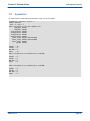
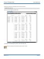
The 'Fedora 16 x86_64 DVD for Ki7 boards' contains Kontron source packages.
These packages are present in the 'SRPMS' folder.
Below an example of source packages available :
cpld-1.2-15111.src.rpm
e1000e-2.3.2-15111.src.rpm
hwtools-1.3.7-15111.src.rpm
ki7_bsp-3.4-15111.fc16.src.rpm
turbostat-1.0-1.fc16.src.rpm
cpld_smi-1.3-15111.src.rpm
flashrom-0.9.9-15111.src.rpm
ixgbe-3.18.7-1.src.rpm
sysvartool-1.7-15111.src.rpm
vmetoolkit-1.6-15111.src.rpm
cpldtool-1.5-15111.src.rpm
fmram-1.1-15111.src.rpm
kernel-3.4.9-15111.ki7.fc16.src.rpm
vpdtool-1.11-15111.src.rpm
Page 4
SD.DT.G11-7e
Fedora 16 Release Notes
Chapter 3 -
Associated Documentation
Associated Documentation
Kontron Documentation
> Hardware
4 VX304x 3U VPX Computing Node User's Guide . . . . . . . . . . . . . . . . . . . . . . . . . . . . CA.DT.A98
4 VX304x Hardware Release Notes . . . . . . . . . . . . . . . . . . . . . . . . . . . . . . . . . . . . . . . . CA.DT.A99
4 VX3035 3U VPX SBC User's Guide . . . . . . . . . . . . . . . . . . . . . . . . . . . . . . . . . . . . . . CA.DT.A95
4 VX3035 Hardware Release Notes . . . . . . . . . . . . . . . . . . . . . . . . . . . . . . . . . . . . . . . . CA.DT.A96
4 VM6050 6U VME SBC User's Guide . . . . . . . . . . . . . . . . . . . . . . . . . . . . . . . . . . . . . . CA.DT.A93
4 VM6050 Hardware Release Notes . . . . . . . . . . . . . . . . . . . . . . . . . . . . . . . . . . . . . . . CA.DT.A94
4 VM6052/VM6054 6U VME SBC User's Guide . . . . . . . . . . . . . . . . . . . . . . . . . . . . . . CA.DT.B16
4 VM6052/VM6054 Hardware Release Notes . . . . . . . . . . . . . . . . . . . . . . . . . . . . . . . . CA.DT.B17
> Firmware
4 VX304x BIOS User Manual . . . . . . . . . . . . . . . . . . . . . . . . . . . . . . . . . . . . . . . . . . . . . SD.DT.F96
4 VX3035 BIOS User Manual . . . . . . . . . . . . . . . . . . . . . . . . . . . . . . . . . . . . . . . . . . . . . SD.DT.F97
4 VM6050 BIOS User Manual . . . . . . . . . . . . . . . . . . . . . . . . . . . . . . . . . . . . . . . . . . . . . SD.DT.F89
4 VM6052/VM6054 BIOS User Manual . . . . . . . . . . . . . . . . . . . . . . . . . . . . . . . . . . . . . SD.DT.G34
Fedora 16 Documentation
> Documentation available at http://fedoraproject.org/
SD.DT.G11-7e
Page 5
Required Configuration
Chapter 4 4.1
4.1.1
Fedora 16 Release Notes
Required Configuration
Hardware Requirements
Hardware Requirements for VX304x Boards
> A Kontron VX304x board.
> The Fedora 16 release may be installed on one of the following bootable disks:
4 a SATA disk connected to the SATA connectors available on VX304x-RTM board.
4 an optional onboard USB Flash Disk.
4 an optional onboard SSD Flash Disk
> A USB DVD-ROM device (for installation from DVD-ROM) or a USB Flash disk generated as described in
chapter 11 “Additional Information” page 77.
> A graphical display (with mini DisplayPort interface), USB keyboard and USB mouse (for a graphics install)
OR
- A console on serial line (text or VNC install).
4.1.2
Hardware Requirements for VX3035 Board
> A Kontron VX3035 board.
> The Fedora 16 release may be installed on one of the following bootable disks:
4 a SATA disk connected to the SATA connectors available on VX3035-RTM board.
4 Optional onboard USB Flash Disk.
> A USB DVD-ROM device (for installation from DVD-ROM) or a USB Flash disk generated as described in
chapter 10 “Create a USB Flash Disk from DVD Iso Image” page 76.
> Graphical display, USB keyboard and USB mouse (for a graphics install) or a console on serial line (text or
VNC install).
4.1.3
Hardware Requirements for VM6050 Board
> A Kontron VM6050 board.
> The Fedora 16 release may be installed on one of the following bootable disks:
4 a SATA disk connected to the SATA connectors available on VM6050-RTM board.
4 Optional onboard USB Flash Disk.
> A USB DVD-ROM device (for installation from DVD-ROM) or a USB Flash disk generated as described in
chapter 10 “Create a USB Flash Disk from DVD Iso Image” page 76.
> A console on serial line (text or VNC install).
For a graphic configuration on VM6050 a specific order code and a specific graphic module are
required: VM6050-2SA34-12110 and MOD-GX-SA-00. The module provides two DP ports and a
VGA connector.
Page 6
SD.DT.G11-7e
Fedora 16 Release Notes
4.1.4
Required Configuration
Hardware Requirements for VM6052/VM6054 Board
> A Kontron VM6052/VM6054 board
> The Fedora 16 release may be installed on one of the following bootable disks:
4 a SATA disk connected to the SATA connectors available on the VM6052-RTM/VM6054-RTM board.
> A USB DVD-ROM device (for installation from DVD-ROM) or a USB Flash disk generated as described in
chapter 10 “Create a USB Flash Disk from DVD Iso Image” page 76.
> a console on serial line (text or VNC install)
For a graphic configuration on VM6052/VM6054, a specific order code and a specific grapic module are
required: VM6052-SA2x-x2xxx or VM6054-SA4x-x2xxx, and MOD-GX-SA-00. The module provides
two DP ports and a VGA connector.
4.2
4.2.1
Firmware Requirements
VX304x Boards
The version of the BIOS firmware must be at least:
> 12332
This version is displayed in the BIOS Setup.
4.2.2
VX3035 Board
The version of the BIOS firmware must be at least:
> 12174
This version is displayed in the BIOS Setup.
4.2.3
VM6050 Board
The version of the BIOS firmware must be at least:
> 11332
This version is displayed in the BIOS Setup.
4.2.4
VM6052/VM6054 Board
The version of the BIOS firmware must be at least:
> 15034
This version is displayed in the BIOS Setup.
SD.DT.G11-7e
Page 7
Required Configuration
4.3
Fedora 16 Release Notes
Software Requirements
> The DVD-ROMs:
4 Fedora 16 x86_64 DVD for Ki7 boards
4 Fedora 16 x86_64 LiveDVD for Ki7 boards
After the release is installed, the release version is saved in /etc/ki7-release:
# cat /etc/ki7-release
Ki7 Board Support Package 3.3 [14085]
> ISO file image: the Kontron DVD can be delivered as ISO image format to customer.
To know how to create a USB flash disk from ISO image on Fedora 16, see chapter 10
“Create a USB Flash Disk from DVD Iso Image” page 76.
Page 8
SD.DT.G11-7e
Required Configuration
Fedora 16 Release Notes
4.4
4.4.1
DVD-ROM Installation Example
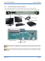
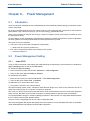
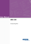
DVD-ROM Installation Example for VX304x Board
1. Plug a DVD-ROM USB device to the front panel USB connector using a standard USB cable.
2. Plug the HDD SATA device on the SATA0-A connector of the Rear Transition Module (VX304x-RTM).
USB 2.0
1
Standard USB cable
DVD-ROM USB device
2
SATA
HDD SATA device
There are 2 USB ports available: one on the front panel and the other one on the RTM board if an RTM is
available. So in order to use a USB keyboard and a USB mouse plus a USB DVD-ROM, a USB HUB is
required.
SD.DT.G11-7e
Page 9
Required Configuration
4.4.2
Fedora 16 Release Notes
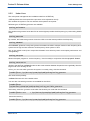
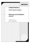
DVD-ROM Installation Example for VX3035
1. Plug a DVD-ROM USB device to the front panel USB connector using a standard USB cable.
2. Plug the HDD SATA device on the SATA0-A connector of the Rear Transition Module (VX3035-RTM).
USB 2.0
1
Standard USB cable
DVD-ROM USB device
2
SATA0-A
Standard SATA cable
HDD SATA device
There are 2 USB ports available: one on the front panel and the other one on the RTM board if an RTM is
available. So in order to use a USB keyboard and a USB mouse plus a USB DVD-ROM, a USB HUB is
required.
Page 10
SD.DT.G11-7e
Required Configuration
Fedora 16 Release Notes
4.4.3
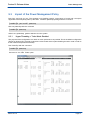
DVD-ROM Installation Example for VM6050
1. Plug a DVD-ROM USB device to the front panel USB connector using a standard USB cable.
2. Plug the HDD SATA device on the SATA0-A connector of the Rear Transition Module (VM6050-RTM).
USB 2.0
1
Standard USB cable
DVD-ROM USB device
2
HDD SATA device
SATA0-A
Standard SATA cable
Graphic configuration on VM6050 requires a specific order code and a specific graphic module:
VM6050-2SA34-12110 and MOD-GX-SA-00. The module provides two DP ports and a VGA connector.
There are 2 USB ports available: one on the front panel and the other one on the RTM board if an RTM is
available. So in order to use a USB keyboard and a USB mouse plus a USB DVD-ROM, a USB HUB is
required.
SD.DT.G11-7e
Page 11
Required Configuration
4.4.4
Fedora 16 Release Notes
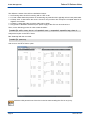
DVD-ROM Installation Example for VM6052/VM6054
1. Plug a DVD-ROM USB device to the front panel USB connector using a standard USB cable.
2. Plug the HDD SATA device on the SATA0-A connector of the Rear Transition Module
(VM6052/VM6054-RTM).
USB 2.0
1
Standard USB cable
DVD-ROM USB device
2
HDD SATA device
SATA0-A
Standard SATA cable
Graphic configuration on VM6050 requires a specific order code and a specific graphic module:
VM6050-2SA34-12110 and MOD-GX-SA-00. The module provides two DP ports and a VGA connector.
There are 2 USB ports available: one on the front panel and the other one on the RTM board if an RTM is
available. So in order to use a USB keyboard and a USB mouse plus a USB DVD-ROM, a USB HUB is
required.
Page 12
SD.DT.G11-7e
Fedora 16 Release Notes
Chapter 5 -
Installation
Installation
This chapter describes the specific steps of the installation process of Fedora 16 on Ki7 boards.
5.1
5.1.1
Disk Installation
Fedora 16 DVD Menu
This section describes the options added to the installation menu on the Fedora 16 x86_64 DVD for Ki7 boards
media.
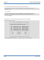
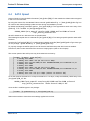
When booting from this media, the following menu appears on the serial line (and also on the graphics display
if present):
*
Welcome to Fedora 16 ki7
*
************************************************************
* Install or upgrade using GRAPHICS mode
*
* Install or upgrade using SERIAL console
*
* Install or upgrade using VNC
*
* Install system with basic video driver
*
* Rescue installed system using GRAPHICS mode
*
* Rescue installed system using SERIAL console
*
* Boot from local drive
*
* Memory test
*
*
*
*
*
*
*
*
*
************************************************************
Select one of these options :
> "Install or upgrade using SERIAL console": to do all the installation using the serial console. However in this
mode, the disk partitioning cannot be customized and only a fixed very minimal set of 200 packages is
installed. Depending on the needed services and libraries, some post installations may be required, so this is
not the recommended method. If possible, install using VNC (see below) or using a graphics display.
> "Install or upgrade using VNC": to start the installation using the serial console, but then use a VNC client on
another system to do the rest of the installation in graphics mode with all installation options available. This
requires the network to be connected to the board.
When installing using the "Install or upgrade using VNC", the default behaviour is to use a DHCP server to
provide the network settings to the board.
If no DHCP server is available, it is possible to provide these settings manually as follows:
> Move the cursor to the "Install or upgrade using VNC line"
SD.DT.G11-7e
Page 13
Installation
Fedora 16 Release Notes
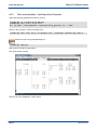
> Press <tab> and append the network settings; at least the IP address :
> vmlinuz initrd=initrd.img console=ttyS0,115200 text stage2=hd:LABEL=”Fedora” vnc
ip=172.20.144.95
or more settings :
> vmlinuz initrd=initrd.img console=ttyS0,115200 text stage2=hd:LABEL=”Fedora” vnc
ip=172.20.161.201 netmask=255.255.255.0 gateway=172.20.161.46 dns=172.20.144.1
> and press <ENTER>
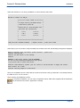
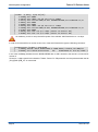
The following menu should be displayed (the Ethernet device list is an example):
Welcome to Fedora for x86_64
***************** Networking Device *****************
*
*
* You have multiple network devices on this system. *
* Which would you like to install through?
*
*
*
* eth0 - Ethernet device eth0 - 00:00:de:40:39:b5 *
* eth1 - Ethernet device eth1 - 00:00:de:40:39:b6 *
* eth2 - Ethernet device eth2 - 00:00:de:40:39:b7 *
* eth3 - Ethernet device eth3 - 00:00:de:40:39:b8 *
* eth4 - Ethernet device eth4 - 00:30:f7:98:2b:00 *
* eth5 - Ethernet device eth5 - 00:30:f7:98:2b:01 *
*
*
*
******
************
********
*
*
* OK *
* Identify *
* Back *
*
*
******
************
********
*
*
*
*
*
*****************************************************
<Tab>/<Alt-Tab> between elements
Page 14
| <Space> selects | <F12> next screen
SD.DT.G11-7e
Installation
Fedora 16 Release Notes
Select the interface to use during installation to connect with the VNC client
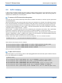
Welcome to Fedora for x86_64
************* Disc Found *************
*
*
* To begin testing the media before *
* installation press OK.
*
*
*
* Choose Skip to skip the media test *
* and start the installation.
*
*
*
*
******
********
*
*
* OK *
* Skip *
*
*
******
********
*
*
*
*
*
**************************************
<Tab>/<Alt-Tab> between elements
| <Space> selects | <F12> next screen
Select Skip if you do not want to verify the validity of the media. At the end, the following messages are displayed:
Running anaconda 14.22, the Fedora system installer - please wait.
19:01:12 Starting VNC...
19:01:14 The VNC server is now running.
19:01:14
WARNING!!! VNC server running with NO PASSWORD!
You can use the vncpassword=<password> boot option
if you would like to secure the server.
19:01:14 Please manually connect your vnc client to 172.20.144.95:1 to begin the install.
Press <enter> for a shell
19:01:18 Starting graphical installation.
Then on a workstation, launch a VNC client to connect to the server running on the board. In the example above,
the VNC server is 172.20.144.95:1
Then continue the installation process.
On a Fedora workstation, you can use the "TigerVNC Viewer" VNC client supplied with the distribution
(can be launched from menu Application / Internet)
SD.DT.G11-7e
Page 15
Installation
5.1.2
Fedora 16 Release Notes
Fedora 16 Installation on Ki7 Boards
This section describes the installation procedure from a USB DVD-ROM drive.
There is no major difference between the installation on the Ki7 boards and the standard Fedora 16 installation,
so refer to the Fedora documentation to get more details on all the Fedora installation menus.
Nevertheless, the Ki7 boards are a graphic board, so the installation may be done in graphic mode or in text mode
on the serial port 0.
1. Insert the DVD Fedora 16 in the DVD-ROM driver.
2. After a board reset, or a board power-on, type <F7> to get the the Boot Manager Menu or <F2> to get the
Setup from the BIOS and to select the DVD-ROM device as the boot device.
3. Select the installation method using the menu, as explained above.
4. Then the standard Fedora 16 Installer menus from anaconda should be displayed.
5. Proceed as a standard Fedora 16 installation.
6. Note that the mezzanine USB Flash device, if present, is probed as another SATA drive.
7. At the end of the installation, reboot on the installed disk drive through the Boot Manager Menu <F7>. The
BIOS Setup menu should be used to set the boot devices priorities. Refer to the BIOS Manual - SD.DT.F96.
It is strongly recommended to disable the swap partition if the installation is done on a USB or SATA flash
device.
5.1.3
LiveDVD Installation on SSD SATA Flash or USB Flash
The LiveDVD media allows to evaluate a new version of Linux in an easy way without degrading data present
on local SATA disk or flash SSD disk.
Another usage of the LiveDVD is the creation of liveUSB on flash devices.
The main advantage of the liveUSB is to prevent, by default, all writing accesses to the flash disk (or USB stick).
It is especially important for some USB flash (stick) or SSD SATA flash devices which do not tolerate a lot of
writing cycles. However it is needed to be able to preserve some changes from one boot to the other one. The
LiveUSB tool features this capability.
Creating a LiveUSB on the SSD flash disk implies the presence of the LiveDVD in the USB DVD-ROM drive.
At first, boot on the LiveDVD in the following way:
4 Insert the Kontron LiveDVD into the USB DVD-ROM drive. You should also have a console connected to the
serial port ttyS0.
4 Under BIOS context, select the USB DVD-ROM drive as the first boot device.
4 At the beginning of the boot step, a first menu should occur.
4 Select the option:
Start FEDORA16 Ki7
4 At the end of the boot step notice the presence of a login on the console.
Using the livecd-iso-to-disk is the easiest way to create a LiveUSB image on a USB stick/SSD disk.
In case you use the media for the first time, you have to re-partition and format your media. To do this, use fdisk.
Page 16
SD.DT.G11-7e
Fedora 16 Release Notes
Installation
For example:
# fdisk /dev/sdX
n
Return
Return
Return
Return
t
6
p
w!
should create a unique partition which covers the whole media.
Then, reformat the media:
# mkfs.vfat -F 32 /dev/sdb1
Write the ISO image to the USB/SSD SATA flash disk using livecd-iso-to-disk:
# ./livecd-iso-to-disk --overlay-size-mb <OVERLAY_SIZE> --force --format /dev/sr0
/dev/sdX1
4 Replace the reference sdX1 by the right one in your particular case.
4 Replace the field <OVERLAY_SIZE> by the value which fits your own configuration (1024 for example will
reserve a 1 Gigabyte writable area).
4 Press <Enter> to launch the process.
Then reboot the board and select the SSD device as new boot device this time.
A menu is displayed proposing 2 choices:
- Start FEDORA16 Ki7
- Troubleshooting
Choose Start FEDORA16 Ki7. As a result, you have access to a complete Fedora 16 x86_64 system including
the BSP specific to the Ki7 board.
Of course, you might customize this system with your own changes. All these changes will be preserved in the
overlay layer.
SD.DT.G11-7e
Page 17
Fedora System Configuration
Chapter 6 -
Fedora 16 Release Notes
Fedora System Configuration
In this chapter, information related to some specific configuration items of the Fedora 16 system are detailed.
6.1
Network
6.1.1
Network Manager
With Fedora 16, the network interfaces are managed by the NetworkManager service by default.
For an embedded system, it is recommended to use the older network service instead which is easier to configure
through configuration files.
For this:
> Disable the NetworkManager service:
[root@ki7]# chkconfig NetworkManager off
> Enable the network service:
[root@ki7]# chkconfig network on
> Stop the network manager: service NetworkManager stop
> Check the configuration files and modify them if needed :
4 /etc/sysconfig/network-scripts/ifcfg-ethx files
4 /etc/resolv.conf
4 /etc/sysconfig/network
> Start the network service: service network start
> Reboot if /etc/sysconfig/network has been modified
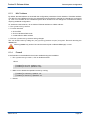
6.1.2
Udev Rule (only for VX304x and VM6052/VM6054)
Kontron udev rule exists to set the onboard Ethernet device name with ethx (where x is the interface number).
This rule is not applied by default and it is convenient only for users.
For example on VM6050/VM6052/VM6054 to set this rule, users need to type the following commands:
cp /etc/udev/rules/75-ki7.vm605x /etc/udev/rules/75-ki7.rules
dracut --force -I /etc/udev/rules.d/75-ki7.rules
The extension file of the udev rule indicates the name of the board. In this example 'vm605x' is a udev rule
for VM6050/VM6052/VM6054.
After relaunching the udev daemon or by rebooting the Linux distribution, the onboard Ethernet device name
should be eth0,eth1,...
Page 18
SD.DT.G11-7e
Fedora 16 Release Notes
6.1.3
Fedora System Configuration
MAC Address
By default, the MAC address is stored with the configuration parameters of each interface. If the MAC address
of a device is found different from the one expected (board changed for example), the interface is not brought
up. This is not suitable for an embedded system when boards must be changed for maintenance without
requiring additional configuration.
To workaround this behavior, do not bind an Ethernet interface to a MAC address:
> Run system-config-network
> For each interface:
4 click on Edit
4 click on Hardware Device tab
4 unselect Bind to MAC address
> Exit from system-config-network saving changes
This can be done also by editing the /etc/sysconfig/network-scripts/ifcfg-eth* files and removing the
HWADDR lines.
Removing HWADDR only works if the service network (and not NetworkManager) is used.
6.1.4
Firewall
If the firewall must be disabled but has been enabled during the installation:
> Run system-config-firewall, click on disable and exit
OR run
[root@ki7]# service iptables stop
[root@ki7]# service ip6tables stop
> Make sure to disable the iptables service by running:
[root@ki7]# chkconfig iptables off
[root@ki7]# chkconfig ip6tables off
> Reboot
SD.DT.G11-7e
Page 19
Fedora System Configuration
6.2
Fedora 16 Release Notes
SELinux
SELinux stands for Security-Enhanced Linux. The Security-Enhanced Linux kernel enforces mandatory access
control policies that confine user programs and system servers to the minimum amount of privilege they require
to do their jobs.
If you experience some trouble running some services or have some permission issues, try to set the System
Default Policy to Permissive instead of Enforcing by running the system-config-selinux tool, or from
command line doing as follows:
4 disable on boot by editing /etc/selinux/config to set SELINUX=permissive instead of
SELINUX=enforcing
4 disable now: setenforce 0
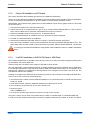
6.3
GRUB Boot Loader
If your console is on the serial line and that access to the grub boot menu is not required on the graphics console,
you should comment the following line in /boot/grub2/grub.conf if present :
terminal --timeout=5 serial console
This will prevent GRUB from waiting 5 seconds to let you select a console by typing a character on one console
to select it.
This setting has nothing to do with the timeout on the boot menu that is set by the line
timeout=<value>
Page 20
SD.DT.G11-7e
Fedora 16 Release Notes
6.4
Fedora System Configuration
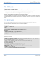
SATA Speed
Kontron introduce in the Ki7 BSP a file named /etc/grub.d/80_ki7 that contains the default value to append
in the Linux command line.
By using this custom file, the standard Fedora comand "grub2-mkconfig -o /boot/grub2/grub.cfg" can
be used for each kernel package update and also during the installation process.
By default the following parameters getfrom /etc/grub.d/80_ki7 are appended to each menu entry of the
grub.cfg file located to /boot/grub2/grub.cfg:
APPEND_LINUX=”pcie_aspm=off console=ttyS0,115200 vmalloc=512MB selinux=0
acpi_enforce_resources=lax”
All SATA interfaces of a Ki7 board are not speed limited.
The following line explain how to customize the /etc/grub.d/80_ki7 for having a specific speed for each SATA
interface.
Once the file /etc/grub.d/80_ki7 is configured and a backup of the file /boot/grub2/grub.cfg is done, type
as root privilege : "grub2-mkconfig -o /boot/grub2/grub.cfg."
To properly manage the SATA speed, first of all check at the BIOS setup that AHCI mode is enabled.
Futhermore, AHCI mode should allow the access to Hotplug option (refer to next chapter).
The current speed of the SATA ports may be checked at boot time by :
[root@ki7 ~]# dmesg | egrep ata[1-9]:
[
2.245738] ata1: DUMMY
[
2.248184] ata2: FORCE: PHY spd limit set to 3Gbps
[
2.253227] ata2: SATA max UDMA/133 abar m2048@0xf0b12000 port 0xf0b12180 irq 44
[
2.260605] ata3: DUMMY
[
2.263047] ata4: DUMMY
[
2.265490] ata5: FORCE: PHY spd limit set to 3Gbps
[
2.270531] ata5: SATA max UDMA/133 abar m2048@0xf0b12000 port 0xf0b12300 irq 44
[
2.277911] ata6: DUMMY
[
2.584377] ata5: SATA link up 1.5 Gbps (SStatus 113 SControl 310)
[
2.584411] ata2: SATA link up 1.5 Gbps (SStatus 113 SControl 310)
To set the speed of the ata2 bus to 3 Gbps and ata5 bus to 1.5 Gbps, modify the APPEND_LINUX entry in the
/etc/grub.d/80_ki7 file :
APPEND_LINUX=”pcie_aspm=off console=ttyS0,115200 vmalloc=512MB selinux=0
acpi_enforce_resources=lax libata.force=2:3.0G,5:1.5G”
Once the file is modified type as root privilege :
[root@ki7 ~]# grub2-mkconfig -o /boot/grub2/grub.cfg
Reboot the machine to have these new settings applied at boot time.
SD.DT.G11-7e
Page 21
Fedora System Configuration
Fedora 16 Release Notes
[root@ki7 ~]# dmesg | egrep ata[1-9]:
[
2.245689] ata1: DUMMY
[
2.248133] ata2: FORCE: PHY spd limit set to 3.0Gbps
[
2.253177] ata2: SATA max UDMA/133 abar m2048@0xf0b12000 port 0xf0b12180 irq 44
[
2.260557] ata3: DUMMY
[
2.263001] ata4: DUMMY
[
2.265445] ata5: FORCE: PHY spd limit set to 1.5Gbps
[
2.270488] ata5: SATA max UDMA/133 abar m2048@0xf0b12000 port 0xf0b12300 irq 44
[
2.277867] ata6: DUMMY
[
2.584331] ata5: SATA link up 1.5 Gbps (SStatus 113 SControl 310)
[
2.607884] ata2: SATA link up 3.0 Gbps (SStatus 123 SControl 320)
It is mandatory for Ki7 to setup the SATA Speed of the onboard SSD Flash device to 1.5 Gbps.
In order to find the SATA bus number under Linux of the SSD Flash device type the following command:
[root@localhost ~]# dmesg | egrep GLS85
[
2.630945] ata5.00: ATA-8: GLS85LS1032A CS 32GBN A101D3, N A101D3, max UDMA/133
[
2.763694] scsi 4:0:0:0: Direct-Access
ATA
GLS85LS1032A CS N A1 PQ: 0 ANSI: 5
In this case the dmesg indicates that the GLS85LS1032A with 32 GB is located to the ata5 bus, means SATA
number 5.
To keep a 1.5 Gbps speed for this interface libata.force=5:1.5G parameter must be preserved when the file
/etc/grub.d/80_ki7 is customized.
Page 22
SD.DT.G11-7e
Fedora System Configuration
Fedora 16 Release Notes
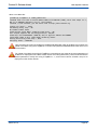
6.5
SATA Hotplug
In AHCI mode, the SATA controller of the Ki7 boards provides a hotplug function. First of all this has to be setup
at BIOS menus (Chipset->South Bridge Configuration->SATA Configuration). After the Hot Plug option is
enabled for the SATA ports, boot the system.
To remove a SATA device from the system:
Close all users of the device and backup device data as needed. Use umount to unmount any file systems that
mounted the device.
Remove the device from any md and LVM volume using it. If the device is a member of an LVM Volume group,
then it may be necessary to move data off the device using the pvmove command, then use the vgreduce com
mand to remove the physical volume, and (optionally) pvremove to remove the LVM metadata from the disk.
If the device uses multipathing, run multipath -l and note all the paths to the device. Afterwards, remove the
multipathed device using multipath -f device.
Run blockdev --flushbufs device to flush any outstanding I/O to all paths to the device. This is particularly
important for raw devices, where there is no umount or vgreduce operation to cause an I/O flush.
Remove any reference to the device's path-based name, like /dev/sd, /dev/disk/by-path or the major:minor
number, in applications, scripts, or utilities on the system. This is important in ensuring that different devices
added in the future will not be mistaken for the current device.
Finally, remove each path to the device from the SCSI subsystem. To do so, use the command:
[root@ki7]# echo 1 > /sys/block/device-name/device/delete
where device-name may be sde, for example.
Nov 10 15:16:24 Ki7 kernel: [10018.256462] sd 1:0:0:0: [sdb] Synchronizing SCSI cache
Nov 10 15:16:24 Ki7 kernel: [10018.534156] sd 1:0:0:0: [sdb] Stopping disk
Nov 10 15:16:24 Ki7 kernel: [10018.934519] ata2.00: disabled
Then you can shut off the device.
To add a SATA device:
When the system is up and running, power on the hotpluggable SATA device and the system should be warned
that a new SATA device is available:
[root@ki7]# dmesg
...
Nov 10 15:22:40 Ki7
Nov 10 15:22:40 Ki7
Nov 10 15:22:40 Ki7
Nov 10 15:22:43 Ki7
Nov 10 15:22:43 Ki7
Nov 10 15:22:43 Ki7
SD.DT.G11-7e
kernel:
kernel:
kernel:
kernel:
kernel:
kernel:
[10394.408164]
[10394.414149]
[10394.420310]
[10396.923493]
[10396.925408]
[10396.925414]
ata2: irq_stat 0x00400040, connection status changed
ata2: SError: { RecovComm PHYRdyChg CommWake DevExch }
ata2: hard resetting link
ata2: SATA link up 3.0 Gbps (SStatus 123 SControl 300)
ata2.00: ATA-8: ST9160314AS, 0001SDM1, max UDMA/133
ata2.00: 312581808 sectors, multi 16: LBA48 NCQ (depth 31/32)
Page 23
Fedora System Configuration
Nov
Nov
Nov
Nov
Nov
10
10
10
10
10
15:22:43
15:22:43
15:22:43
15:22:43
15:22:43
Ki7
Ki7
Ki7
Ki7
Ki7
kernel:
kernel:
kernel:
kernel:
kernel:
Fedora 16 Release Notes
[10396.927836]
[10396.927846]
[10396.927991]
[10396.928246]
[10396.928299]
Nov 10 15:22:43 Ki7 kernel: [10396.928398]
Nov 10 15:22:43 Ki7 kernel: [10396.928443]
Nov 10 15:22:43 Ki7 kernel: [10396.928772]
Nov 10 15:22:43 Ki7 kernel: [10396.955136]
ata2.00: configured for UDMA/133
ata2: EH complete
scsi 1:0:0:0: Direct-Access ATA ST9160314AS\0001 PQ: 0 ANSI: 5
sd 1:0:0:0: Attached scsi generic sg1 type 0
sd 1:0:0:0: [sdb] 312581808 512-byte logical blocks: \
(160 GB/149 GiB)
sd 1:0:0:0: [sdb] Write Protect is off
sd 1:0:0:0: [sdb] Write cache: enabled, \
read cache: enabled, doesn't support DPO or FUA
sdb: sdb1 sdb2
sd 1:0:0:0: [sdb] Attached SCSI disk
If automount services are enabled, the partitions should be mounted too.
6.6
VITA 57
Using VX3830 IO cards for VPX boards or VM6050, it is possible to use the VITA 57 option. Kontron is delivering
a toolkit to help the setup and development of application using the onboard FPGA and the FMC modules defined
though the VITA 57 standard. Refer to your representative to get more information about this option.
6.7
VXFabric
Kontron VXFabric™ is an open infrastructure which implements efficient inter board communication at hardware
speed. The architecture is compliant with the OpenVPX standard (VITA 65) which defines two main hardware
topologies of the backplane: distributed and centralized topologies.
To get more information about this software, go to the www.kontron.com web site and enter the key word
"vxfabric" into the search engine.
Page 24
SD.DT.G11-7e
BSP Specific Features
Fedora 16 Release Notes
Chapter 7 7.1
7.1.1
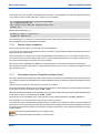
BSP Specific Features
Sensors
Sensors Overview
The BSP contains an RPM named sensors_addons that configures the standard lm_sensor software for the Ki7
boards.
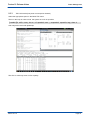
To display sensors information:
[root@ki7]# sensors
Example on VX304x
[root@ki7]# sensors
acpitz-virtual-0
Adapter: Virtual device
temp1:
+37.0°C (crit = +106.0°C)
temp2:
+36.0°C (crit = +106.0°C)
nct7802y-i2c-22-28
Adapter: I2C CPLD adapter
3V3 SB (A/D REF):
+3.24 V (min =
Processor Vcore :
+0.86 V (min =
1V5 Memory
:
+1.52 V (min =
12V VPX VS1
:
+12.10 V (min =
5V VPX VS3
:
+4.99 V (min =
VPX 3V3 aux
:
+0.00 V
nct7802y local temp: +30.0°C (low =
+0.18
+0.00
+0.40
+0.13
+0.78
V,
V,
V,
V,
V,
max
max
max
max
max
=
=
=
=
=
+0.38
+0.00
+0.04
+1.34
+1.15
V)
V)
V)
V)
V)
-40.0°C, high = +85.0°C)
coretemp-isa-0000
Adapter: ISA adapter
Physical id 0: +38.0°C (high = +87.0°C, crit = +105.0°C)
Core 0:
+35.0°C (high = +87.0°C, crit = +105.0°C)
Core 1:
+31.0°C (high = +87.0°C, crit = +105.0°C)
Core 2:
+34.0°C (high = +87.0°C, crit = +105.0°C)
Core 3:
+32.0°C (high = +87.0°C, crit = +105.0°C)
pchtemp-pci-00fe
Adapter: PCI adapter
temp1:
+43.5°C
The sensor command reveals the presence of low, high and critical thresholds. When the temperature temp1
goes beyond the critical threshold, an automatic reset of the board will occur.
When the temperature or the voltage goes beyond one of the limits low and high, an explicit alarm message will
occur in the sensors command output. So, in order to track down this kind of event, run the following command:
[root@ki7]# sensors | grep ALARM
SD.DT.G11-7e
Page 25
BSP Specific Features
Fedora 16 Release Notes
On the other hand, it is possible to synchronize the execution of an application on a high limit temperature event.
For example, at first, create a file name /tmp/test.sh containing:
cd /sys/devices/platform/i2c-cpld.6/i2c-22/22-0028
cat < temp1_max_alarm_intr
echo 'Nuvoton local temp went beyond the high limit'
shutdown now
Make it executable and run it:
[root@ki7]# chmod +x /tmp/test.sh
[root@ki7]# /tmp/test.sh
As a consequence, in case the nuvoton temperature goes beyond the high limit temperature, this shell script
will automatically cause a shutdown of the board.
7.1.2
Sensors Values Limitations
The sensors named "acpitz-virtual-0" has some limitations.
For these sensors, which are internal to the CPU, Intel does not guarantee the validity of temperature value in
high level range of temperature.
The Kontron BIOS, to inform the user that the temperature probe validity is not correct, return the value -56°C.
So if a probe of these sensors value returns -56°C, it does not mean that the board is currently running at -56°C,
but it only means that the probe value can not be reliable.
The sensor named "pchtemp-pci-00fe" has some limitations as indicated in the Intel documentations.
The temperature range of this sensors is approximately between 40°C to 130°C. Temperature below 40°C will
be truncated to 40°C.
7.1.3
Temperature Sensors Threshold and Alarm Report
The LM73 and/or Nuvoton NCT7802Y have some minimum and maximum thresholds configured by the BIOS.
Linux drivers present in this distribution for these temperature sensors, implement a polling mechanism to report
alarms.
Alarms are set by the driver, and reported by 'sensors' command.
When the temperature fetches on one of these sensor devices is lower than the minimum threshold the alarm
is set and the 'sensors' command report 'ALARM (LOW)'.
When the temperature fetches on one of these sensor devices is higher than the maximum threshold the alarm
is set and the 'sensors' command report 'ALARM (HIGH)'.
The interrupt mode is available only for the nct7802y by the module parameter 'nct7802y_smbalert'.
This parameter is set at 0 that means the interrupt mode is not active.
If the interrupt mode is activated, the thresholds must be modified. It is necessary to fit the mode pre-configured
by the BIOS. This mode set the interrupt when the temperature is higher than the maximum threshold, and unset
the interrupt when the temperature is lower than the minimum threshold. In this case both threshold must have
positive values.
The lower temperature threshold is a negative value.
The higher temperature threshold is a positive value
Page 26
SD.DT.G11-7e
Fedora 16 Release Notes
7.1.4
BSP Specific Features
Voltage Sensors Threshold and Alarm Report
Only the Nuvoton NCT7802Y manages lower and higher limits.
Only the polling mode is implemented in the Nuvoton NCT7802Y device driver.
'ALARM (MIN)' is reported by 'sensors' command when sensor value is lower than the minimum threshold.
'ALARM (MAX)' is reported by 'sensors' command when sensor value is higher than the maximum threshold.
SD.DT.G11-7e
Page 27
BSP Specific Features
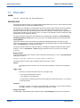
7.2
Fedora 16 Release Notes
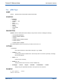
CPLD-WDT
NAME
cpld-wdt * Kontron board cpld_wdt watchdog driver
DESCRIPTION
This man page describes how to use the watchdog implemented by the cpld on various Kontron boards
including the VX304x, VX3035 and VM605x families.
The principle of a watchdog is to automatically provoke some action after a given time passes without
the watchdog being prodded by some process. This would indicate that the process is no longer
working correctly. The cpld_wdt watchdog actions are to do nothing, to reset the board, to generate an
interrupt that can wake up some other process, or to reboot. The prodding is done by writing to the wat
chdog device, which restarts the timeout.
The cpld_wdt module implements the standard Linux watchdog API, detailed in file Documentation/
watchdog/watchdog*api.txt in the kernel source rpm. The supported features are described below.
Loading Module
There can be many devices and modules providing the watchdog API. Ensure only the cpld_wdt
module is being used. For example, the standard iTCO_wdt watchdog module is usually blacklisted by
a file in /etc/modprobe.d/ to avoid it being loaded.
The cpld_wdt module has to be explicitly loaded, for example by creating a systemd file with a name
ending in ".conf" in /etc/modules*load.d/ listing the modules to load, one per line, for example:
cpld_wdt
Module Options
To provide initial options to the module, create a file with a name ending in ".conf" in /etc/modprobe.d/
holding a line such as:
options cpld_wdt timeout=50 trigger_mode=1 nowayout=1
The module options, shown by the command "modinfo cpld_wdt", include
timeout
the integer timeout in seconds, from 0 to 510 with a resolution of 2 seconds. The default is
30.
trigger_mode
the action to do when the timeout expires. An integer value
• 0 to simply countdown with no action,
• 1, the default, to reset the board,
• 2 to generate an interrupt that can be used to wake up a read on the device, or to reboot if
no read is pending.
nowayout
an integer 1 if there is no way to stop the watchdog. The default is 0, which stops the timer if
the magic character "V" is written just before the device is closed.
Usage from Scripts
The watchdog is implemented with the standard device /dev/watchdog. This file can accept ioctls to
Page 28
SD.DT.G11-7e
Fedora 16 Release Notes
BSP Specific Features
configure the watchdog, but can be used simply from a shell script as follows: Load the module with the
required configuration, for example to interrupt, with a timeout of 10 seconds:
[root@ki7]# rmmod cpld_wdt
[root@ki7]# modprobe cpld_wdt timeout=10 trigger_mode=2 nowayout=0
Start the watchdog by writing to the device:
[root@ki7]# echo >/dev/watchdog
Prod the watchdog faster than every 10 seconds:
[root@ki7]# while sleep 5; do echo >/dev/watchdog; done
After a while stop the loop and wait for a timeout:
[root@ki7]# cat /dev/watchdog
This will hang for 10 seconds. If you wait another 10 seconds without issuing another read, the OS will
reboot. To stop the watchdog instead:
[root@ki7]# echo V >/dev/watchdog
To avoid the need to be root, simply change the ownership or permissions of /dev/watchdog.
Watchdog Ioctl API
The following standard ioctls are supported.
WDIOC_GETSUPPORT
#include <linux/watchdog.h>
struct watchdog_info ident;
ioctl(fd, WDIOC_GETSUPPORT, &ident);
returns in the structure the fields
identity
the driver identification "cPLD WDT"
firmware_version
is always 1
options
describes the supported features, namely WDIOF_KEEPALIVEPING and
WDIOF_SETTIMEOUT.
WDIOC_SETTIMEOUT
int timeout = ...;
ioctl(fd, WDIOC_SETTIMEOUT, &timeout);
sets the timeout in seconds.
WDIOC_GETTIMEOUT
ioctl(fd, WDIOC_GETTIMEOUT, &timeout);
returns the current timeout setting in the argument (not the dynamically changing counter
value).
WDIOC_SETOPTIONS
SD.DT.G11-7e
Page 29
BSP Specific Features
Fedora 16 Release Notes
int options = ...;
ioctl(fd, WDIOC_SETOPTIONS, &options);
configures the given options. These are WDIOS_DISABLECARD to disable the watchdog, and
WDIOS_ENABLECARD to enable the watchdog.
WDIOC_KEEPALIVE
ioctl(fd, WDIOC_KEEPALIVE, 0);
prods the watchdog, restarting the countdown timer.
SEE ALSO
cpld(4)
cpldtool(1)
FILES
/dev/watchdog
Documentation/watchdog/watchdog*api.txt
COPYRIGHT
Kontron
Page 30
SD.DT.G11-7e
Fedora 16 Release Notes
7.3
BSP Specific Features
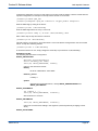
VPD Tool
NAME
vpdtool * display Kontron board VPDs (Vital Product Data)
SYNOPSIS
*a boardtype
**boardtype
**conffile or *f file
**eclevel
**help or *h
**human or *H
**keylist
**macaddr
**serialnumber
**variant
DESCRIPTION
vpdtool reads the VPDs (Vital Product Data) of many Kontron boards, including the following:
• ITC320/322 PENTXM2/4
• VM6050 VM6052 VM6054
• VM6250
• VX3020 VX3030 VX3035 VX3040
• VX3230 VX3240
• VX6060 VX6070 VX6080
As it reads hardware ports via /dev/mem you need to be root to run it.
OPTIONS
*a boardtype
forces the architecture of the board to that given, e.g. VX3020
**conffile or *f file
uses the given features definition file. This file says how to convert the vpd binary encodings
into text descriptions.
**help or *h
prints an option summary.
**human or *H
displays features of the board in a human readable way.
**boardtype **eclevel **keylist **macaddr **serialnumber **variant
displays only the requested information. The options can be combined.
EXAMPLE
$ sudo vpdtool **human
VM6050 detected
SD.DT.G11-7e
Page 31
BSP Specific Features
Fedora 16 Release Notes
i2cbus_num = 22
Board type
: VM6050*2SA34*01110
EC Level
: EC02005
Serial Number: 1811401050021
Variant
: 1020004180850000
Keylist
: /PCB_B/SACLASS/P2GPIOOFF/BHQUAD/IOFPGAON/IBOMOFF/PCIEMUXGEN2/NOJTAGPCH/XMC/COREI7LVK0/PWRMAGOFF/BATON/STD_EARTH/IRTC/XDPON/STDCLK/
CK505REFOSC/XMCPWR12VOFF/2GB_DDR3_1333/P0PWRMAGOFF/P0UHM/SATAHDD/2RANK/VME/
PXMC/1SLOT/FP422ON/FL/P80OFF/ITIN/I2CSTD/P5VOFF/NOFPIO/PMCON/JTAGON/
Features
:
PCB B
SA Class
No GPIOs 7 & 8 on P2
Quad link NH82580
IO FPGA no DDR2 with FMC
Normal BOM generation
PCIe mux GEN2
PCH JTAG is not available on XDP connector
XMCA and XMCB equipped
Low Voltage 620LE Core*i7 2GHz K0
Front magnetic power option off
Battery present
Standard EARTH connection
PCH internal RTC configuration
XDP port available
Standard clock option
CK505 oscillator source configuration
5V XMC power rail
2GB DDR3*1333 device
P0 magnetic power option off
P0 type is UHM
SATA equipped for VM6250 HDD carrier
Both rank equipped
vme 2esst available
PMC P64s, XMC X8d+X12d IOs available
1 VME slot version for SA
Front panel RS*422 option on
Use of SnPb component only
P80 debug option not available on debug connector
PCB plating: Immersion Tin
CPLD I2C equipment: one F*RAM, one EEPROM
No P5V only
No front IO option
PMC connector fitted on board
JTAG connector fitted on board
FILES
/dev/mem
/dev/i2c/*
COPYRIGHT
Kontron
Page 32
SD.DT.G11-7e
BSP Specific Features
Fedora 16 Release Notes
7.4
LEDs
The driver leds_cpld handles the front panel LEDs for user mode.
The driver leds_cpld creates a list of special files and classes in /sys:
[root@ki7]# ls /sys/class/leds/
led2:amber led2:OFF led3:amber
led2:green led2:red led3:green
led3:OFF
led3:red
For each LED, there are three different colors available: green, red, amber that can be set by addressing the
related file.
For each color (which are exclusive), there are four different modes:
4 ON (echo 0, see following example)
4 slow blinking (echo 1, see following example)
4 fast blinking (echo 2, see following example)
4 OFF (echo 1, see following example)
Example, to set these different modes on the LED 2 in amber:
[root@ki7]#
[root@ki7]#
[root@ki7]#
[root@ki7]#
echo
echo
echo
echo
0
1
2
0
>
>
>
>
led2:amber/brightness The LED
led2:amber/brightness The LED
led2:amber/brightness The LED
led2:OFF/brightness The LED 2
2 is ON in AMBER
2 blinks low in AMBER
2 blinks fast in AMBER
is OFF
When setting led2 or led3, both led2 and led3 are set to user mode.
To exit from this mode, set led<n>:OFF/brightness to a non null value; for example
[root@ki7]# echo 1 > led2:OFF/brightness
> VX304x: On the front panel, the name of the led1 is L1, led2 is L2 and led3 is L3.
The led1 (L1 and L4) is not manageable at user level, so no special file for led1 is available.
SD.DT.G11-7e
Page 33
BSP Specific Features
7.5
Fedora 16 Release Notes
Multinodes Diskless
Multinodes Diskless is a powerful set of python scripts to help the configuration of diskless root filesystems and
to boot distant nodes through the Ethernet network (PXE).
The main command is diskless:
[root@ki7] diskless --help
There are two xml files to configure the diskless system:
/etc/diskless/images.xml: describes the layers, the nodes and main configuration setup.
/etc/diskless/diskless_fs.xml: lists the rpms used to build the root filesystem of the distant nodes;
The user manual is available at: /usr/local/share/doc/diskless/pdf/manual.pdf
If diskless is not needed, you can disable this service at boot time :
[root@ki7]# chkconfig diskless off
7.5.1
Introduction
When you have several Ki7 boards in your machine, you can use one of the board as a diskless server.
Most of the time, it will be the first board present in a chassis but it is not mandatory. It must be equiped with
a SATA hard disk ( or SATA SSD ).
Of course, you won't need any disk media present on the other targets providing that the targets will boot on the
diskless server through the network (that is the point).
The package multinodes-diskless is available to setup and configure a NFS exportable root filesystem and to
get a kernel and a initrd bootable through PXE.
The diskless product is incompatible with SELINUX enforcing policy as well as iptables services.
So run the following commands in order to disable these services:
4 Stop the iptables service and disable SELINUX by running the commands:
[root@ki7]# chkconfig iptables off
[root@ki7]# service iptables stop
4 Set the variable SELINUX=disabled in the file: /etc/selinux/config
The following steps describe how to initialize a diskless configuration and how to boot it on a given number of
targets.
7.5.2
Get the whole Fedora 16 Distribution on a Local Repository
The very first step is to get a local repository on the diskless server of the Fedora 16 RPM packages.
To do this, insert the Fedora 16 DVD and run these commands :
[root@ki7]#
[root@ki7]#
[root@ki7]#
[root@ki7]#
[root@ki7]#
Page 34
mkdir -p /dist/Fedora_16_ki7_boards/{BSP,RPMS}
mount /dev/dvd /mnt
cp /mnt/Packages/* /dist/Fedora_16_ki7_boards/RPMS
cd /dist/Fedora_16_ki7_boards
createrepo .
SD.DT.G11-7e
Fedora 16 Release Notes
BSP Specific Features
Then code the right value into the following field of the /etc/diskless/diskless_fs.xml:
<baseurl>file:///dist/Fedora_16_ki7_boards/</baseurl>
In this way the diskless tool will know the location of the Fedora 16 RPMs just installed.
The next step is to build a diskless root file system based on these Fedora 16 RPMs.
7.5.3
Build the diskless RFS ( root file system )
Force the layer building even if it already exists by running:
[root@ki7]# diskless -B
The command will take a few minutes to complete.
The content of the RFS is defined in the section named <rpms> present in the xml file /etc/diskless_fs.xml
If you want change the content of the RFS, for example in order to add your own package, simply add the package
name to the list.
Be careful when you change one of the xml files : / e t c / d i s k l e s s / i m a g e s . x m l or
/etc/diskless/diskless_fs.xml . Keep a copy of the initial version.
You should notice the presence of two layers under /diskless/layers
[root@ki7]# ls /diskless/layers
fedora_base fedora_config
with
4 fedora_base:
Containing the reference root file system.
4 fedora_config:
A customizable layer you can change as you want.
For example, if you want to use your own /etc/hosts file, simply install it under /diskless/layers/fedora_con‐
fig by running:
[root@ki7]# cp --parents /etc/hosts /diskless/layers/fedora_config
In this way, the target(s) after booting throught the network will "see" your own /etc/hosts file instead of the
reference one (in fact, from the diskless client point of view, the layer fedora_config overloads the underneath
fedora_base layer).
The RFS is now ready. The next step is to configure the DHCP server as well as the PXE boot.
7.5.4
Configure the DHCP and PXE Services in MAC Ethernet Address Mode
This step is mandatory to authorize remote targets to boot over the LAN on the diskless server.
Two modes are available for this purpose:
4 MAC Ethernet mode: in this mode the IP address delivered by the DHCP server depends on the MAC
Ethernet address of the target board.
4 GEOID mode: in this mode the IP address delivered by the DHCP server depends on the location of the target
board in the chassis.
SD.DT.G11-7e
Page 35
BSP Specific Features
Fedora 16 Release Notes
This section presents the MAC Ethernet adress mode. The next one presents the GEOID Ethernet addres mode.
Of course both of them are exclusive.
At first, uncomment if needed the XML structure called <nodemap id=”MAC_ADDR-diskless-cluster”..> in the
file /etc/diskless/image.xml and comment out the one related to the GEOID mode.
Then code the right MAC Ethernet address (related to the network interface used during the boot step) into this
field:
<match criterium=”macaddress”>
<value>00:00:xx:xx:xx:xx</value>
</match>
From the server side, configure the network interface em1 (for example) with the right address with the command:
[root@ki7]# ifconfig em1 192.168.1.1
If you want to use a different network base address, simply code this in the field <ip>192.168.1.% (1+order.‐
value)</ip> of the structure <nodemap>.
Start the required service tftpd by running the command:
[root@ki7]# chkconfig tftp on
Finally run the command:
[root@ki7]# diskless -x
Verify the right files have been created under /diskless/tftp:
[root@ki7]# cd /diskless/tftp
[root@ki7]# find .
The created files should be:
./pxelinux.0
./pxelinux.cfg
./pxelinux.cfg/default
Another impact of the diskless -x command is the starting of the DHCPD daemon.
So verify all worked well in this area by running:
[root@ki7]# service dhcp status
The output should include: active (running)
At this step, unless you want to configure diskless in GEOID mode, go directly to the section 7.5.6 Export the Root File System.
7.5.5
Configure the DHCP and PXE Services in GEOID Ethernet Address Mode
An alternative to the MAC address mode is the GEOID mode. In this mode the IP address delivered by the DHCP
server depends on the location of the target board in the chassis.
This mode is interesting in the sense that it allows you to replace a board by another one without changing the
configuration file: image.xml (because the MAC Ethernet address, specific to each board, is not coded into the
image.xml file in this case).
Page 36
SD.DT.G11-7e
Fedora 16 Release Notes
BSP Specific Features
Indeed, in this case, it is required to code the GEOID range into the image.xml file instead of the explicit MAC
addresses related to the boards plugged into the rack.
So edit the file /etc/diskless/image.xml, uncomment the right XML structure called <nodemap id=”GEOID-disk‐
less-cluster”..>... and comment out the one related to the MAC-ADDR mode.
Then, code the right GEOID value into this file (field <match criterium=”geoid”>).
In order to take into account the previous change, run the following command:
[root@ki7]# diskless -x
At this step, the DHCPD daemon should be ready as well as the TFTPD one.
7.5.6
Export the Root File System
The diskless RFS based on aufs (which implements the different stackable layers ) must be exported now.
To do this, use this command:
[root@ki7]# diskless -e
Finally start the NFSD service with the command:
[root@ki7]# service nfs-server start
and verify the status is correct.
[root@ki7]# service nfs-server status | grep Active
At this step, the remote target should be ready to be booted in diskless mode.
Reboot the server to take into account the previous changes.
7.5.7
Boot the Target through the Network
On the diskless target and after a power-on, enter BIOS setup on CPUB by pressing <F2>.
Under BIOS Setup, select successively the menus: Chipset ->South Bridge -> Ibex Peak Option and enable the
PXE boot (example given on VM6050).
Save the changes and after reset, press again <F2>.
Select the menu "boot" and put the network device at the top of the list.
Save the change and exit. As a result the PXE boot will happen and the following should be displayed:
CLIENT MAC ADDR: 00 00 DE 40 36 F9
GUID: 00020003 0004 0005 0006
000700080009
DHCP.|
You should notice the occurence of a login at the end of the boot step.
Log in as root and verify the system is operational.
SD.DT.G11-7e
Page 37
BSP Specific Features
7.5.8
Fedora 16 Release Notes
Diskless Service
To automate the launching of the diskless at the boot step, simply enable the related service by running :
chkconfig diskless on
In this case, the next time you boot the server, the service diskless will be launched.
As result the commands diskless -x and diskless -e will be run automatically, authorizing the diskless boot
of the target.
7.5.9
Initiate a Reset of the Remote Targets
[root@ki7]# diskless -aR
Should cause a reset of all the remote targets.
Page 38
SD.DT.G11-7e
Fedora 16 Release Notes
7.6
BSP Specific Features
Sysvartool
To get the report of the PBIT (Power Built In Test), run the command:
[root@ki7]# sysvartool -A pbit -l
VX304x detected
area = 2, arch = 2
POSTs configured to run from command line:
mem_data: PASSED
mem_addr: PASSED
mem_pattern1: PASSED
mem_pattern2: PASSED
mem_pattern3: PASSED
mem_pattern4: PASSED
ether_loop0: PASSED (FAILED ONCE)
ether_loop1: PASSED (FAILED ONCE)
ether_loop2: PASSED
system: PASSED
PASSED
FAILED
NOT RUN
TOTAL
:
:
:
:
10
0
0
10
POSTs configured to run automatically from RAM:
PASSED
FAILED
NOT RUN
TOTAL
:
:
:
:
0
0
0
0
POSTs configured to run automatically from ROM:
PASSED
FAILED
NOT RUN
TOTAL
:
:
:
:
0
0
0
0
SD.DT.G11-7e
Page 39
BSP Specific Features
7.7
Fedora 16 Release Notes
GPIOs
NAME
cpld-gpio - Kontron board gpio-cpld driver gpios
DESCRIPTION
This man page describes how to use the gpios implemented by the cpld on various Kontron boards
including the VX304x, VX3035 and VM605x families.
The cpld gpio driver provides an API using files in the /sys filesystem. Reads and writes to the files are
directly handled by the driver, provoking reads and writes of hardware registers. Reads normally return
a short string terminated with a newline. Further reads need to seek back to the start of the file or reopen it. Writes should normally be of a single string, optionally terminated with a newline. Writing values
other than those described below are undefined, but usually result in a write error with errno EINVAL
Invalid argument.
Usage from Program
Operations can be easily done from a shell script. When used from a program, open the files for simul
taneous read and write, except for "intr_stat" (read only). Read in one go into a buffer big enough to
accept the whole reply, including newline (i.e 11 characters). Use lseek(2) to rewind the file descriptor
before each read. Write each value using a single system call. There is no need to lseek before writes.
Permissions
By default the files are owned by root and only writeable by the owner. If necessary, these ownerships
and permissions can be changed (each time the driver is loaded), for example by a udev rule.
Sysfs Files
There is one directory per gpio, starting with gpio1, under the class directory:
/sys/class/cpld-gpio/
The number of gpios depends on the board. Each directory has the following files. The string values
described are those that can be written, or will be read.
direction holds the value "in" (incoming signal) or "out" (outgoing). The default is "in". For example:
[root@ki7]# echo out >/sys/class/cpld−gpio/gpio4/direction
[root@ki7]# cat /sys/class/cpld−gpio/gpio4/direction
out
value holds the value "0" (low signal) or "1" (high). On read return the current value of the gpio. On write
sets the value of an outgoing gpio. For example:
[root@ki7]# echo 0 > /sys/class/cpld−gpio/gpio4/value
[root@ki7]# cat /sys/class/cpld−gpio/gpio3/value
1
polarity holds the value "hi" (interrupt when signal active on high level or rising edge), or "lo" (active on
low level or falling edge). The default is "hi".
mode holds the value "edge" (interrupt on rising or falling edge) or "level" (on high or low level). The
default is "edge".
toggle holds the value "on" (interrupt on any state change) or "off" (interrupt only on the configured pola
rity and mode). When on it overrides the polarity and mode settings. The default is "off".
interrupt holds the value "on" (enable interrupts) or "off" (disable). When an interrupt occurs in level
mode, this value is automatically reset to "off" to avoid a permanent interrupt. The default is "off".
Page 40
SD.DT.G11-7e
Fedora 16 Release Notes
BSP Specific Features
intr_stat is a read-only count of the number of interrupts received on the gpio. This is an unsigned 32
bit decimal value which can be up to 10 digits long, plus a newline. This file is read-only, and writing to
it will result in a write error of EPERM Permission denied, or EIO Input/output error. For example:
$ cat /sys/class/cpld−gpio/gpio5/intr_stat
12
value_it on read waits for an interrupt on the gpio, and then returns a string of length zero. If interrupts
have not been enabled, the file acts like the value file. The file acts like the value file for all writes.
To get an interrupt you must set the direction, polarity, mode, toggle and interrupt files appropriately, and
then read value_it until it returns, or poll the intr_stat value until it changes.
Dual Purpose GPIO
On some boards, gpio2 is a dual purpose gpio which can also be used to generate a Maskable Reset. It
is configured using cpld registers that can be set using cpldtool, or low level port accesses.
To check if the board provides this feature run the command:
[root@ki7]# cpldtool −a|grep MSKR2LOC
If MSKR2LOC is not found, gpio2 is not dual purpose. To configure gpio2 as a standard gpio which
does not issue a local reset, on a VPX board:
[root@ki7]# cpldtool −f VPX_CONTROL MSKR2LOC 0
on a VME board:
[root@ki7]# cpldtool −f VME_CONTROL MSKR2LOC 0
or on either type of board specify the register by number instead:
[root@ki7]# cpldtool −f 0x70 MSKR2LOC 0
Use the same command with value 1 to restore the configuration. To do the same using low level port
accesses, read the register and calculate the new value before writing it back. For example:
[root@ki7]# port 0x870
@0x870 = 0x1d
[root@ki7]# port 0x870 0xd
@0x870 <− 0x0d
[root@ki7]# port 0x870
@0x870 = 0x0d
SEE ALSO
cpld(4)
cpldtool(1)
FILES
/sys/devices/platform/cpld_gpios/cpld-gpio/gpio[1-8]
COPYRIGHT
Kontron
SD.DT.G11-7e
Page 41
BSP Specific Features
7.8
Fedora 16 Release Notes
cpldtool
NAME
cpldtool - Kontron board cPLD register utility
SYNOPSIS
-a
-d register
-f register fieldname hexvalue ...
-i register
-s register hexvalue
-v
DESCRIPTION
This utility interprets, displays, and sets flags in registers of the cPLD on Kontron boards including the
VX3230, VM6250, VX3030 and VX6060. The cPLD is a small device that controls some low-level
aspects of the board. See cpld(4). You need to be root to access the device. Do not change register
values accept as advised by Kontron.
OPTIONS
Registers should be given as a decimal number, or hexadecimal number prefixed by 0x, whereas
register content hexvalues are always assumed to be hexadecimal, whether prefixed or not.
-a displays all registers and interprets the bitfield flags as appropriate.
-d register displays the current value of the given register.
-i register displays information on the given register, naming each bitfield and saying where it starts.
-s register hexvalue sets the given register to the given hexadecimal value.
-f register fieldname hexvalue ... sets the given register field by field. Each field is specified by field
name, as shown by option -i, and the hexadecimal value for that field.
-v more verbose output for the -a and -d options, detailing what some values mean.
EXAMPLES
Describe register 9:
[root@ki7]# cpldtool −i 9
Ref 0x9 − FLASH MEMORY PROTECT
Field name: Boot flash CS swap DIP (7)
Explanation:
Boot flash chip select configuration
0 : Normal configuration
1 : Rescue configuration
...
Field name: USER WP (3)
Explanation:
USER level WP hardware protection
0 : No USER level WP correction
1 : USER level WP active
Page 42
SD.DT.G11-7e
Fedora 16 Release Notes
BSP Specific Features
Show the current value of fields in register 9:
[root@ki7]# cpldtool −d 9
Reg 0x9 − FLASH MEMORY PROTECT = 0x00
Boot flash CS swap DIP=0x0
Boot flash CS swap Valid#=0x0
Boot both flash=0x0
USER WP=0x0
SYS WP=0x0
VPD WP=0x0
VPX NVMRO=0x0
Set the "USER WP" bitfield in register 9:
[root@ki7]# cpldtool −f 9 ’USER WP’ 1
SEE ALSO
cpld(4)
COPYRIGHT
Kontron
SD.DT.G11-7e
Page 43
BSP Specific Features
7.9
Fedora 16 Release Notes
I2C Busses
The cpld_i2c driver is supporting the local i2c bus (I2C bus number 22) which is local to the board and used
to address sensors and system eeproms.
There are also two other I2C busses routed to the backplane; the bus numbers are 23 and 24:
4 /dev/i2c-23 is the SMB bus connecting it to the I2C devices in the chassis (if any).
4 /dev/i2c-24 is the IPMB bus connecting all boards through the backplane
By default, those two busses are available only on the system controller.
It is possible to enable those busses on other slots by adding the option force_i2c_extend=1 at the load of
the module "cpld". Add this argument "cpld.force_i2c_extend=1" at the kernel command line to enable this
option.
7.10 BIOS Update
The flashrom package provides a set of commands and scripts to update the BIOS of the boards.
To update the BIOS of the Ki7 boards, use the command ki7updbios:
Help command:
[root@ki7]# ki7updbios -h
usage:
/usr/local/sbin/ki7updbios <options> <bios image>
Script to update the BIOS on boards using flashrom tools.\n
Options:\n
-r Read the current BIOS in bios image file.\n
-w Update the BIOS image using the given bios image file.\n
-a Update the all BIOS eeprom.\n
[root@ki7]#
Read the current BIOS:
[root@ki7]# ki7updbios -r BIOS.bin
flashrom v0.9.4 on Linux 2.6.32.14-11035.vx304x.fc12.i686.PAE (i686), built with libpci 3.1.7,
GCC 4.4.2 20091027 (Red Hat 4.4.2-7), little endian
flashrom is free software, get the source code at http://www.flashrom.org
Calibrating delay loop... OK.
No coreboot table found.
Found chipset ”Intel QM57”, enabling flash write... OK.
This chipset supports the following protocols: FWH,SPI.
Found chip ”SST SST25VF032B” (4096 KB, SPI) at physical address 0xffc00000.
Reading flash... done.
[root@ki7]# ls -ltr BIOS.bin
-rw-r--r-- 1 root root 4194304 2011-03-03 15:54 BIOS.bin
Page 44
SD.DT.G11-7e
Fedora 16 Release Notes
BSP Specific Features
Write a new BIOS file:
[root@ki7]# ki7updbios -w vx304x_ID12xxx.bin
flashrom v0.9.4 on Linux 2.6.32.14-11035.vx304x.fc12.i686.PAE (i686), built with libpci 3.1.7,
GCC 4.4.2 20091027 (Red Hat 4.4.2-7), little endian
flashrom is free software, get the source code at http://www.flashrom.org
Looking for ”bios”... found.
Calibrating delay loop... OK.
No coreboot table found.
Found chipset ”Intel QM57”, enabling flash write... OK.
This chipset supports the following protocols: FWH,SPI.
Found chip ”SST SST25VF032B” (4096 KB, SPI) at physical address 0xffc00000.
Flash image seems to be a legacy BIOS. Disabling checks.
Erasing and writing flash chip... Done.
Verifying flash... VERIFIED.
Take care that if the system is booted from the RESCUE BIOS flash (refer to the BIOS user manual), the
update of the BIOS using the ki7updbios command will update the RESCUE BIOS Flash which is not
recommended.
The update of the BIOS through the ki7updbios command does not preserve the setup parameters of
the BIOS. For deployement of a BIOS version with its own setup parameters, preset one board with the
desired parameters, backup this using ki7updbios -r, and use this version of BIOS+ setup to be
deployed on other similar boards.
SD.DT.G11-7e
Page 45
BSP Specific Features
Fedora 16 Release Notes
7.11 FMRAM Example
The fmram packages gives an example of how access to the FMRAM device which may be used to save some
customer data which needs to be backuped.
[root@ki7]# fmram -h
Usage fmram [options]
a tool to read or write the FerroMagnetic RAM
Options are :
-h
-r
-w
-s
-f
<value>
<value>
<value>
<filename>
: this help
: read at offset <value> (default 0)
: write at offset <value> (default 0)
: data size to read or write (default 4)
: file name used to store (optional) or read (mandatory) data
Example:
fmram -w 0x10 -s 0x11 -f data_file :
store 17 bytes read from data_file to the ferromagnetic RAM at offset 16
With src package, the C code of this command is delivered as an example.
Page 46
SD.DT.G11-7e
Fedora 16 Release Notes
BSP Specific Features
7.12 VME
7.12.1
ALMAVME
NAME
almavme - Alma VME Linux toolkit driver API
SYNOPSIS
Kernel API (from a kernel driver)
#include <almavme.h>
int alma_pci_channel_alloc(char *name, u32 vmeaddr, unsigned long pciaddr, u32 size, u32 flag);
int alma_pci_channel_free(int id);
unsigned long alma_vme_channel_alloc(char *name, u32 vmeaddr, u32 size, u32 flag);
int alma_vme_channel_free(unsigned long address);
u32 alma_cpuadr_to_vmeadr "(unsigned long address);
int alma_user_dma(u32 vmeaddr,unsigned long pciaddr,u32 size,u32 flags);
int alma_user_dma_mcast(u32 vmeaddr, unsigned long pciaddr,u32 size,u32 flags,u32 select);
int alma_get_vme(void);
int alma_free_vme(void);
int alma_ctrl(int command, int config);
int request_vmeirq(unsigned int vector, void *handler);
int free_vmeirq(unsigned int vector);
void alma_vmeintcontrol(unsigned int mask, unsigned int ienable);
int disable_vmeirq(u32 level);
int enable_vmeirq(u32 level);
int alma_vmeinterrupt(unsigned char level, unsigned char vector);
int alma_phys_mem_alloc(struct alma_phys_mem_object *phys_mem);
int alma_phys_mem_free(struct alma_phys_mem_object *phys_mem);
User Space API (from an application)
#include <linux/almavme.h>
int fd = open("/dev/almavme", O_RDWR);
if(fd<0){
perror("Error opening the almavme device");
exit(1);
}
alma_ioctl_arg_t alma_ioctl;
alma_ioctl.intr.level = 1;
alma_ioctl.intr.vector = 2;
int error = ioctl(fd, VMEIOCTL_VMEINTR_GEN, &alma_ioctl);
close(fd);
See the User Space sections below.
DESCRIPTION
This describes the kernel service calls available for VME device drivers or application development on
Kontron platforms using the almavme driver for all boards equipped with Alma2e and Alma2f.
Alma2f provides a highly integrated single chip solution to interface a VME64 bus with 2eSST protocol
(two-edge Source-Synchroneous Transfer) and a 32-bit 66 MHz PCI Bus. All bridge features are prog
rammable from the PCI bus or the VME bus. See the Alma2f User Manual CI.DT.A00.
SD.DT.G11-7e
Page 47
BSP Specific Features
Fedora 16 Release Notes
In the following, functions are described from the kernel point of view, and examples show how to call
them from a user application.
User Space Ioctls
All ioctls take a command argument, and an appropriate struct as third argument. As alma_ioctl_arg_t
is a union of most of the possible struct types, it can be used as a suitable third argument for most of the
ioctls. The descriptions below assume the following usage:
alma_ioctl_arg_t A;
A... = ...;
ioctl(fd,command,&A);
VME Access
All accesses to or from the VMEbus go through the PCI32 bus and the PCI-to-VME bridge hardware.
No specific windows (slave or master) are opened at load time by the almavme device driver (except for
the slave window to access Alma register space (A16) that is inherited from the firmware setup on
VMPCx and PN3 boards). See the "Mapping Service Calls" section below on how to open slave or
master windows.
Mapping Service Calls
alma_pci_channel_alloc
int alma_pci_channel_alloc(char *name, u32 vmeaddr, unsigned long pciaddr,u32 size,u32 flag)
This allocates a slave channel from the VME to the PCI (i.e. incoming accesses to the board). Up to 15
channels can be opened, 8 of them support 2ESST (see the 2ESST section). The parameters of the
routine describe the VME-PCI channel:
name is the name of this channel. It can be up to 12 bytes long, including the final null char. It is only
used to label this channel in the list of channels printed by the almavmechan(1) utility.
vmeaddr is the VME physical address where the board will respond on the VME. It must be aligned
to a 1MB boundary and also to the rounded-up channel size.
pciaddr is the physical address generated on the board when the PCI/VME bridge responds to the
vmeaddr address on the VME bus. The address can be in PCI-IO space, PCI-MEM space or DRAM
space (the flag field defines which one is used). It must be aligned to a 1 MB boundary and to the
rounded-up channel size.
size is the size of the channel. It must be a multiple of 1 MB and it is rounded up to a power of 2.
flag contains the options for the channel. Options are 'ored' from the following:
MEFG_WRTPOST access is write posted (default NO)
VMEFG_READAHEAD access is read ahead (default NO)
VMEFG_LEBE_xx defines the little/big endian conversion mode (default is address coherency)
* The pci space which is one of:
VMEFG_PCIIO access PCI-IO
VMEFG_PCIMEM access PCI-MEM
VMEFG_DRAM access DRAM (default).
* The AM code, which is decoded on the VMEbus for this channel. The default is
VMEFG_AM_A32SDATA (0x0D). An AM code is specified as either:
VMEFG_AM_xxx flags that predefine standard AM codes, or
Page 48
SD.DT.G11-7e
Fedora 16 Release Notes
BSP Specific Features
VMEFG_AM_DIRECT ored with multiple AM selecting bitmasks. The bitmask 0x0FF00000
defines which AM[5..3] are valid and the bitmask 0x000FF000 defines which AM[2..0] are
valid. Each acceptable value of AM[2..0], i.e. the eight values 0 to 7, is selected by setting a
bit in the bitmask, (1<<12) for 0, (1<<13) for 1, etc. To simplify, the VMEFG_AMSLV_xxx
flags can be used when several AM codes must be decoded. This is below the defined set of
available AMs:
A32 USER MBLT (AM 0x08) fg = 0x00201013
A32 USER DATA (AM 0x09) fg = 0x00202013
A32 USER PROG (AM 0x0A) fg = 0x00204013
A32 USER BLT (AM 0x0B) fg = 0x00208013
A32 SUPER USER MBLT (AM 0x0C) fg = 0x00210013
A32 SUPER USER DATA (AM 0x0D) fg = 0x00220013
A32 SUPER PROG (AM 0x0E) fg = 0x00240013
A32 SUPER BLT (AM 0x0F) fg = 0x00280013
A24 USER MBLT (AM 0x38) fg = 0x08001013
A24 USER DATA (AM 0x39) fg = 0x08002013
A24 USER PROG (AM 0x3A) fg = 0x08004013
A24 USER BLT (AM 0x3B) fg = 0x08008013
A24 SUPER USER MBLT (AM 0x3C) fg = 0x08010013
A24 SUPER USER DATA (AM 0x3D) fg = 0x08020013
A24 SUPER USER PROG (AM 0x3E) fg = 0x08040013
A24 SUPER USER BLT (AM 0x3F) fg = 0x08080013
A16 USER (AM 0x29) fg = 0x02002013
A16 SUPER (AM 0x2D) fg = 0x02020013
A16 LCK (AM 0x2C) fg = 0x02010013
A16 USER, A16 SUPER, A16 LCK can not be used to initialize a VME to PCI memory window due
to the current driver window size definition that must be higher or equal to 1MB. A24 USER MBLT,
A24 SUPER USER MBLT are identify as AM that present some transfer error. For these cases
please contact the Kontron support.
This routine returns an identifier from 0 to 15 on success and -1 on failure. It can be called from user space with
the ioctl() VMEIOCTL_PCI_CHAN_ALLOC.
alma_pci_channel_free
int alma_pci_channel_free(int id)
This is used by the VME driver to free a VME-PCI channel allocated by alma_pci_channel_alloc(). The
parameter id is the channel identifier returned by alma_pci_channel_alloc(). It returns 0 on success, -1
on failure. It can be called from user space with the ioctl VMEIOCTL_PCI_CHAN_FREE.
alma_vme_channel_alloc
unsigned long alma_vme_channel_alloc(char *name, u32 vmeaddr, u32 size, u32 flag)
This allocates an outgoing master channel from PCI to VME. The parameters of the routine describe the
desired PCI-VME channel:
name is the name of this channel. It can be up to 12 bytes long, including the final null char. It is only
used to label this channel in the list of channels printed by the alma_vmechan utility.
vmeaddr is the VME physical address generated by the board. It must be aligned to 8 MB.
size is the size of the channel. It must be a multiple of 8 MB, and less than 256 MB.
flag contains the options for the channel. Options are 'ored' from the following:
VMEFG_WRTPOST access is write posted (default NO). It must be used with a BLT or MBLT
channel.
SD.DT.G11-7e
Page 49
BSP Specific Features
Fedora 16 Release Notes
VMEFG_READAHEAD access is read ahead (default NO). It must be used with a BLT or MBLT
channel.
VMEFG_LEBE_xx defines the little/big endian conversion mode (default address coherency).
VMEFG_PCIIO access is from PCI-IO to VME (default is access from PCI-MEM to VME). There
is no difference between PCI-MEM and PCI-IO.
AM code. One of the predefined VMEFG_AM_xxx flags. The default is VMEFG_AM_A32SDATA
(0x0D AM code).
This routine returns the CPU physical address on success and -1 on failure. The CPU physical address to be
used by the Operating System or a user program can be mapped using the routine mmap(). This routine can be
called from user space with the ioctl VMEIOCTL_VME_CHAN_ALLOC.
alma_vme_channel_free
int alma_vme_channel_free(unsigned long address)
This is used by the VME driver to free a PCI-VME channel allocated by alma_vme_channel_alloc().
address is the pointer returned by alma_vme_channel_alloc().
This routine returns 0 on success and SYSERR on failure. It can be called from user space with the ioctl
VMEIOCTL_VME_CHAN_FREE.
alma_cpuadr_to_vmeadr
u32 alma_cpuadr_to_vmeadr(unsigned long address)
This returns the VME address that can be used to get at the given cpu physical address, or -1 if not
visible from the VME.
User Space Mapping Service
ioctl(fd, VMEIOCTL_PCI_CHAN_ALLOC , &A)
does alma_pci_channel_alloc(A.pcichan.name, A.pcichan.vmeaddr, A.pcichan.pciaddr, A.pcichan.
size, A.pcichan.flag)
ioctl(fd, VMEIOCTL_PCI_CHAN_FREE , &A)
calls alma_pci_channel_free(A.index)
ioctl(fd, VMEIOCTL_VME_CHAN_ALLOC , &A)
returns alma_vme_channel_alloc(A.vmechan.name, A.vmechan.vmeaddr, A.vmechan.size, A.vmec
han.flag)
ioctl(fd, VMEIOCTL_VME_CHAN_FREE , &A)
calls alma_vme_channel_free(A.addr)
For example (from MasterSgl.c).
char *devName = ”mychan”;
alma_ioctl.vmechan.name = devName; // Name
alma_ioctl.vmechan.vmeaddr = aBaseAddr; // VME Physical Address
alma_ioctl.vmechan.size = PCIVME_BLKSIZE; // As small as possible (8 MB)
alma_ioctl.vmechan.flag = VMEFG_AM_A32UDATA;
physAddr = ioctl(fd, VMEIOCTL_VME_CHAN_ALLOC, &alma_ioctl);
if(physAddr==− 1){
printf(”vmeOpen: VME channel open / VMEIOCTL_VME_CHAN_ALLOC fail:
Page 50
SD.DT.G11-7e
Fedora 16 Release Notes
BSP Specific Features
%s\n”,devName);
return (ERROR);
}
virtualAddr = (unsigned long)mmap(0, PCIVME_BLKSIZE, PROT_READ |
PROT_WRITE,
MAP_SHARED, fd, (off_t)(physAddr&0xFFFFFFFF));
if(virtualAddr==− 1){
printf(”vmeOpen: VME channel open: mmap fail: %s\n”,devName);
ioctl(fd, VMEIOCTL_VME_CHAN_FREE, &physAddr);
}
DMA Operations
The VME/PCI bridge includes two physical DMA channels that can copy data between PCI and VME
buses. DMA bounce buffers are allocated if necessary, i.e. if the flags say the source or destination area
is a virtual address.
Note that by default each DMA transfer is 4 kB (a page). Contact Kontron for other possibilities.
alma_user_dma
int alma_user_dma(u32 vmeaddr,unsigned long pciaddr,u32 size,u32 flags)
This executes a dma between the given vmeaddr and a pci, cpu physical or user virtual address,
depending on the flags. It returns 0 on success.
vmeaddr is the VME physical address.
pciaddr is by default the DRAM logical address and DMA buffers are allocated. If the flag
VMEFG_DMA_PADDR is set, it is the cpu physical DRAM address and DMA buffers are not allo
cated, but the dart or iommu is programmed and the address converted to a pci bus physical
address. If the flag VMEFG_DMA_PCIADDR is set, it is the pci bus physical DRAM address and
DMA buffers are not allocated, and no change is made to the address, no dart or iommu entries are
made.
size is the size of the transfer in bytes. It is divided by 4 kB to get the number of DMA transfers.
flags contains the options for the channel. Options are 'ored' from the following:
VMEFG_DMA_VMEPCI the DMA is VME read and PCI write (default is PCI read VME write)
VMEFG_LEBE_xx define the little/big endian conversion mode (default is address coherency)
AM code. One of the predefined VMEFG_AM_xxx flags can be used. The default is
VMEFG_AM_A32SDATA (0x0D AM code).
VMEFG_DMA_CHBKSIZ changes the number of VME cycles in each block (default is 8). Note
that the maximum number of cycles in a block is 256 and that the number of cycles are numbered
starting from 0 (0 = 1 cycle, 1 = 2 cycles, etc.). The number of cycles uses the bitmask
0x0000FF00, so the blocksize has to be shifted left 8 and then 'ored' with a flag. For example, to
set 256 VME cycles in each block, 'or' ((256-1)<<8)|VMEFG_DMA_CHBKSIZ with the other
flags. Usually performance is improved by increasing the blocksize.
This does as alma_user_dma() but uses 2ESST broadcast cycles. Flags should include
VMEFG_AM_2ESST and VMEFG_XAM_A64BDCST. The select mask has a bit set for the geo
graphic id of each remote board that should accept the broadcast (little-endian bits 1..21). See
the section on 2ESST below.
User Space DMA Operations
ioctl(fd, VMEIOCTL_DMA_START, &A)
SD.DT.G11-7e
Page 51
BSP Specific Features
Fedora 16 Release Notes
calls alma_user_dma(A.dma.vmeaddr, A.dma.data, A.dma.size, A.dma.flag).
ioctl(fd, VMEIOCTL_DMA_START_MCAST, &A)
calls alma_user_dma_mcast(A.mcast.vmeaddr, A.mcast.data, A.mcast.size, A.mcast.flag, A.mcast.
select). This feature is not available on Alma2f.
For example:
dma_arg.vmeaddr = strtoul(argv[1], NULL, 0); // VME address
size = strtoul(argv[2], NULL, 0);
dma_arg.dmaaddr = malloc(size); // DMA buffer
if (dma_arg.dmaaddr == NULL) {
fprintf(stderr,” Error allocating DMA buffer\n”);
exit(1);
}
dma_arg.size = size; // size
if (argc <= 3) // Optional channel
dma_arg.flag = VMEFG_AM_A32SDATA|VMEFG_DMA_VMEPCI;
else
dma_arg.flag = strtoul(argv[3],NULL,0);
printf(” VME Addr: 0x%x, DMA buf: 0x%p, Size: 0x%x, Flags: 0x%x\n”,
dma_arg.vmeaddr,dma_arg.dmaaddr, dma_arg.size, dma_arg.flag);
err = ioctl(fd, VMEIOCTL_DMA_START, &dma_arg);
if (err != −1) {
unsigned int *ptr = (unsigned int *) dma_arg.dmaaddr;
for (i = 0; i < dma_arg.size/28; i++) {
printf(”[0x%p] %x %x %x %x %x %x %x\n”,
ptr, ptr[0], ptr[1], ptr[2],
ptr[3], ptr[4], ptr[5], ptr[6]);
ptr += 7;
}
}
Contiguous Memory Allocation
The following routines allocate and free the physically contiguous memory needed for dma.
alma_phys_mem_alloc
int alma_phys_mem_alloc(struct alma_phys_mem_object *phys_mem)
This allocates a contiguous physical memory area. In the phys_mem parameter, only phys_mem->size
needs to be set to the requested size, which can be up to 64 Mbytes. It returns 0 on success, -1 on fai
lure. It can be called from user space with the ioctl VMEIOCTL_PHYSICAL_MEM_ALLOC.
alma_phys_mem_free
int alma_phys_mem_free(struct alma_phys_mem_object *phys_mem)
This frees a previously allocated contiguous physical memory area. In the phys_mem parameter, only
phys_mem->cpu_phys_addr needs to be set to the address of the physical memory area. It returns 0
on success, -1 on failure. It can be called from user space with the ioctl VMEIOCTL_PHY
SICAL_MEM_FREE.
User Space Contiguous Memory Allocation
ioctl(fd, VMEIOCTL_PHYSICAL_MEM_ALLOC , struct alma_phys_mem_object *phys_mem)
calls alma_phys_mem_alloc(phys_mem).
Page 52
SD.DT.G11-7e
Fedora 16 Release Notes
BSP Specific Features
ioctl(fd, VMEIOCTL_PHYSICAL_MEM_FREE , struct alma_phys_mem_object *phys_mem)
calls alma_phys_mem_free(phys_mem).
For example (taken from the almavmechan tool):
mem_obj.size = ...;
rc = ioctl(fd,VMEIOCTL_PHYSICAL_MEM_ALLOC,&mem_obj);
printf(”0x%x\n”,mem_obj.cpu_phys_addr);
mem_obj.cpu_phys_addr = ...;
rc = ioctl(fd,VMEIOCTL_PHYSICAL_MEM_FREE,&mem_obj);
Locking
The VME bus can be explicitly locked before one or more accesses are done. It must always be paired
with a free. These routines return 0 on success. On the VM605x board, the VME bus should be locked
before issuing a simgle VME access concurrently with VME DMA accesses.
alma_get_vme
int alma_get_vme(void)
alma_free_vme
int alma_free_vme(void)
User Space Locking
ioctl(fd, VMEIOCTL_GET_VME, 0)
calls alma_get_vme()
ioctl(fd, VMEIOCTL_FREE_VME , 0)
calls alma_free_vme().
For example:
void fcop_withcapturevmebus(u32 *dst, u32 *src, u32 size){
int ret = ioctl(fd,VMEIOCTL_GET_VME,0); // Capture the VME Bus
if (ret==0) {
fcop(dst,src,size); // Do the job
ret = ioctl(fd,VMEIOCTL_FREE_VME,0); // Release the VME Bus
}
}
VME/PCI Bridge Configuration
Some parameters can be changed in the VME/PCI bridge, such as request level, release mode, and
arbitration.
alma_ctrl
int alma_ctrl(int command, int config)
If command is ACTL_GET_CONFIG the config is ignored, and the current configuration is returned. If
command is ACTL_SET_CONFIG, the given config becomes the new VME/PCI bridge configuration,
and 0 is returned. The config format is the following (bit 0 is the LSB):
request level is coded in the 3 LSB: ALMACFG_REQLEVELx for level x (from 0 to 3 inclusive). The
default value is level 3.
SD.DT.G11-7e
Page 53
BSP Specific Features
Fedora 16 Release Notes
fair mode is coded in bit 3 (ALMACFG_FAIRMODE). If active, the VME/PCI bridge does not request
the VME if another VME device requests it on the same level.
bus release mode is coded in bits 4..6 (ALMACFG_BUSREL_MSK). Four modes are supported:
ALMACFG_BUSREL_ROR (release on request), ALMACFG_BUSREL_RWD (release when done),
ALMACFG_BUSREL_ROC (release on clear) and ALMACFG_BUSREL_RNE (release never). The
default mode is ALMACFG_BUSREL_ROR.
fair mode timeout is coded in bit 7 (ALMACFG_FAIRTIMEOUT).
system controller is coded in bit 17 (ALMACFG_SYS_CTRL). It is READ ONLY. If active, the VME/
PCI bridge is the VME system controller.
arbitration type is coded in bit 16 (ALMACFG_ROT_PRIO). If the VME/PCI bridge is the system
controller, this bit sets the arbitration type: 0 fixed priority, 1 rotating priority.
timeout is coded in bits 8..15 (ALMACFG_TIMEOUTMSK). If the VME/PCI bridge is the system
controller, these bits are the timeout value in microseconds for data transfer on the VMEbus. For
example, if the timeout is 120 and if there is no response to a VME request after 120 microseconds,
the VME/PCI bridge will generate a bus error on the VMEbus.
VME speed is coded in bit 20 and 21 with ALMACFG_SPEED_XXXX. There are three modes: slow,
medium and fast. It programs the device to different speeds for VME 2ESST cycles.
This routine can be called from user space with the ioctls VMEIOCTL_SET_ALMACFG
and VMEIOCTL_GET_ALMACFG. It is possible to get the VMEbus and release the VMEbus by software;
alma_get_vme() gets the VMEbus and alma_free_vme() releases the VME bus. These routines can be called from
user space with the ioctls VMEIOCTL_GET_VME and VMEIOCTL_FREE_VME.
User Space VME/PCI Bridge Configuration
ioctl(fd, VMEIOCTL_SET_ALMACFG, &A)
calls alma_ctrl(ACTL_SET_CONFIG,A.almacfg)
ioctl(fd, VMEIOCTL_GET_ALMACFG, 0)
returns alma_ctrl(ACTL_GET_CONFIG,0)
Read() and Write() Primitives
The VME driver read() and write() primitives offer direct user access to VMEbus space, using the AM
code specified by the VMEIOCTL_SET_RWAM ioctl command. The DMA is used to do reads and
writes without remapping of VME buffers in kernel or user space. /dev/almavme and any /dev/vmeX
may be used to read/write on the VME. The usual lseek(2) system call can be used to change the
vmeaddr.
User Space Read() and Write() Configuration
ioctl(fd, VMEIOCTL_SET_RWAM, &A)
sets the AM code to be used by the driver's read() and write() entry points from A.defam.
ioctl(fd, VMEIOCTL_GET_RWAM, &A)
returns in A.defam the current AM code used by the driver's read() and write() entry points.
For example:
vmeaddr = strtoul(argv[1],NULL,0); // VME address
size = strtoul(argv[2], NULL, 0);
buffer = malloc(size); // DMA buffer
Page 54
SD.DT.G11-7e
Fedora 16 Release Notes
BSP Specific Features
if (buffer == NULL) {
fprintf(stderr,” Error allocating DMA buffer\n”);
exit(1);
}
if (argc <= 3) // Optional channel
flags = VMEFG_AM_A32SDATA;
else
flags = strtoul(argv[3],NULL,0);
printf(” VME Addr: 0x%x, DMA buf: 0x%p, Size: 0x%x, Flags: 0x%x\n”,
vmeaddr, buffer, size, flags);
err = ioctl(fd, VMEIOCTL_SET_RWAM, &flags); // Set the AM
err = lseek(fd, vmeaddr, SEEK_SET); // Set vmeaddr offset
err = read(fd, buffer, size); // Read data into buffer
if (err != −1) {
unsigned int *ptr = (unsigned int *) buffer;
for (i = 0; i < size/28; i++) {
printf(”[0x%p] %x %x %x %x %x %x %x\n”,
ptr, ptr[0], ptr[1], ptr[2],
ptr[3], ptr[4], ptr[5], ptr[6]);
ptr += 7;
}
}
Interrupt Service Calls
The VME driver associates interrupt vectors with handlers by calling the routines request_vmeirq() and
free_vmeirq(). The VME irq level may be masked/unmasked using alma_vmeintcontrol().
request_vmeirq
int request_vmeirq(unsigned int vector, void *handler)
Assign a handler to a specific VME vector. If the vector is between 8 and 15, it is for an addressed inter
rupt (see below). Otherwise, it is a VME irq vector from 0 to 255.
free_vmeirq
int free_vmeirq(unsigned int vector)
Release the specified vector.
alma_vmeintcontrol
void alma_vmeintcontrol(unsigned int mask, unsigned int ienable)
This masks or unmasks one or several interrupt levels.
mask is a 16 bit bitfield where each bit is associated with an interrupt level except bit 0. Bit n
corresponds to the interrupt level n on the VMEbus.
ienable is 0 to mask and non-zero to unmask all the interrupt levels set in mask.
disable_vmeirq
int disable_vmeirq(u32 level)
This deprecated routine disables a single VME interrupt level, from 1 to 7.
enable_vmeirq
int enable_vmeirq(u32 level)
SD.DT.G11-7e
Page 55
BSP Specific Features
Fedora 16 Release Notes
This deprecated routine enables a single VME interrupt level, from 1 to 7.
alma_vmeinterrupt
int alma_vmeinterrupt(unsigned char level, unsigned char vector)
This sends an interrupt on the VMEbus. Vector must be a multiple of 8. The interrupt vector generated is
(vector+level).
User Space Interrupt Service
ioctl(fd, VMEIOCTL_VMEINTR_GEN , &A)
calls alma_vmeinterrupt(A.intr.level,A.intr.vector)
ioctl(fd, VMEIOCTL_VMEINTR_CTRL, &A)
calls alma_vmeintcontrol(A.intrctl.mask,A.intrctl.enable)
ioctl(fd, VMEIOCTL_VMEIOINTSET, &A)
connects interrupt A.vector to the VME driver, and returns an identifier that can be used with
VMEIOCTL_INTRWAIT and VMEIOCTL_VMEIOINTCLR.
ioctl(fd, VMEIOCTL_VMEIOINTCLR, &A)
disconnects interrupt A.index from the VME driver.
ioctl(fd, VMEIOCTL_INTRWAIT, &A)
waits for an interrupt connected by VMEIOCTL_VMEIOINTSET. A.index is the identifier returned by
VMEIOCTL_VMEIOINTSET.
For example, generating an interrupt:
lvl = strtol(argv[1], NULL, 0); // VME IRQ level
vect = strtol(argv[2], NULL, 0); // VME vector
printf(”Level = 0x%lx, Vector = 0x%lx\n”, lvl, vect);
alma_ioctl.intr.level = (u32) (lvl&0xFFFFFFFF);
alma_ioctl.intr.vector = (u32) (vect&0xFFFFFFFF);
err = ioctl(fd, VMEIOCTL_VMEINTR_GEN, &alma_ioctl);
For example, waiting for an interrupt:
lvl = strtol(argv[1], NULL, 0);
vect = strtol(argv[2], NULL, 0);
alma_arg.vector = (vect&0xFF); // Vector
printf(”Init handling for interrupt level %d and vector 0x%x (0x%x)\n”,
lvl, vect, alma_arg.vector);
fflush(stdout);
Id = ioctl(fd, VMEIOCTL_VMEIOINTSET, &alma_arg);
// Enable the interrupt lvl
alma_arg.intrctl.mask = (1 << lvl); // VME IRQ level
alma_arg.intrctl.enable = 1; // Enable the IRQ
err = ioctl(fd, VMEIOCTL_VMEINTR_CTRL, &alma_arg);
printf(”Wait for interrupt level %d (vector 0x%x) id=%d...\n”, lvl, vect,
Id);
fflush(stdout);
alma_arg.index = Id; // Id in the user vector table
err = ioctl(fd, VMEIOCTL_INTRWAIT, &alma_arg);
printf(”RECEIVED\n”);
fflush(stdout);
Page 56
SD.DT.G11-7e
Fedora 16 Release Notes
BSP Specific Features
// Disable the interrupt lvl
alma_arg.intrctl.mask = (1 << lvl); // VME IRQ level
alma_arg.intrctl.enable = 0; // Disable the IRQ
err = ioctl(fd, VMEIOCTL_VMEINTR_CTRL, &alma_arg);
printf(”Disable VME IRQ level %d\n”, lvl);
alma_arg.index = Id; // Id in the user vector table
err = ioctl(fd, VMEIOCTL_VMEIOINTCLR, &alma_arg);
Addressed Interrupts
There is another way to transmit an interrupt across the VMEbus using addressed interrupts. A byte
write into a special register of the VME/PCI bridge will generate an interrupt on the board. A driver can
choose to discriminate between eight different sources of addressed interrupts. The VME/PCI bridge
registers can be accessed from the VMEbus in A16 mode. The A16 base address is setup by firmware
(VMEID) on a 256 byte boundary, and extends for 256 bytes. To generate an addressed interrupt, write
a byte at address (ALMAbase + 0xEE). The byte should have a value of (1<<x), where x is from 0 to 7
inclusive, chosen by the programmer. To receive addressed interrupts use request_vmeirq().
For example:
vmea16_addr = strtol(argv[3], NULL, 0); // VME A16 addr
printf(”Adressed VME interrupt %ld remote A16:0x%lx\n”, lvl−8,
vmea16_addr);
alma_ioctl.vmechan.name = ”GENintr”; // Name
alma_ioctl.vmechan.vmeaddr = 0; // VME Physical Address
alma_ioctl.vmechan.size = PCIVME_BLKSIZE; // As small as possible (8 MB)
alma_ioctl.vmechan.flag = VMEFG_AM_A16S;
physaddr = ioctl(fd, VMEIOCTL_VME_CHAN_ALLOC, &alma_ioctl);
vaddr = (unsigned long) mmap(0, vmea16_addr + 0x100 /*size of A16 window*/,
PROT_READ | PROT_WRITE, MAP_SHARED, fd, (off_t)(physaddr&0xFFFFFFFF));
if(vaddr==−1){
printf(”A16 VME channel open fail\n”);
ioctl(fd, VMEIOCTL_VME_CHAN_FREE, &physaddr);
exit(1);
}
printf(”VME_addr:0x%lx paddr:0x%lx vaddr:0x%lx\n”, vmea16_addr, physaddr,
vaddr);
write_addr = (char*) (vaddr + vmea16_addr + 0xee);
write_val = (char)(1<<(lvl−8));
printf(”WRITING 0x%x at 0x%p\n”, write_val, write_addr);
*write_addr = write_val;
sync();
printf(”READING 0x%x at 0x%p\n”, *write_addr, write_addr);
sync();
munmap((void *)vaddr, 0x100); // size of A16 window
ioctl(fd, VMEIOCTL_VME_CHAN_FREE, &physaddr);
Further IOCTL() Commands
The following commands are also available:
ioctl(fd, VMEIOCTL_VME_CHAN_GETIO , struct pcivme_window *p)
copies the PCI-IO to VME channel descriptions into the third arg. It is N structures of type struct
pcivme_window, where N is the number of PCI-IO to VME channels opened.
ioctl(fd, VMEIOCTL_VME_CHAN_GETMEM , struct pcivme_window *p)
copies the PCI-MEM to VME channel descriptions into the third arg. It is N structures of type struct
pcivme_window, where N is the number of PCI-MEM to VME channels opened.
ioctl(fd, VMEIOCTL_VME_CHAN_GETNB , &A)
SD.DT.G11-7e
Page 57
BSP Specific Features
Fedora 16 Release Notes
returns in A.vmechannb.mem the number of PCI-MEM to VME channels opened and in A.vmec
hannb.io the number of PCI-IO to VME channels opened.
ioctl(fd, VMEIOCTL_PCI_CHAN_GET, struct vmepci_window *p)
copies the VME to PCI channel descriptions into the third arg. It is 7 structures of type struct
vmepci_window.
ioctl(fd, VMEIOCTL_PCI_CHAN_GETEXT, struct vmepci_window *p)
copies the VME to PCI channel descriptions into the third arg. It is MAXVMEPCIWIN structures of
type struct vmepci_window.
ioctl(fd, VMEIOCTL_SET_BOARDID , int *ga)
set the GA (Geographical Address) for opening an A16S VME window pointing the the Alma bridge
registers. Note that if the 'ga' value is equal to 0xff, the current GA of the board is not modified. Fur
thermore if 'ga' equal to -1 than this window is closed.
Sysfs Files
The driver provides files under the sysfs "vme" class directory, /sys/class/vme/almavme. These
can be read or written.
/sys/class/vme/almavme/vme_bus_error
A read of this file returns as a string the number of VME bus errors seen by the driver. Any write will
clear the counter.
2ESST
The Alma PCI/VME bridge implements 2ESST (Two Edge Source Synchronous Vme Transfer). This is
an extension to the VME64 standard to allow the VME bus to operate at much greater speeds of nomi
nally 160, 267 and 320 Mbytes/second, between boards supporting the extension.
2ESST transfers use a new address modifier (AM) code, and so are ignored by boards that do not
support them. The supervisory/non-privileged and program/data sub-modes are replaced by a new
extended address modifier (XAM). The data transmitter uses both edges of the clock to strobe data and
does not wait for any acknowedgement (two edge source synchronous). 64 bits (8 bytes) of data are
clocked on each edge. Transmissions must use an even number of edges, so the minumum unit of
transfer is 16 bytes, though it is possible to flag the last cycle as ignored. It is not optimal to transfer only
16 bytes of data. A maximum of 128 beats of 2 edges of 8 bytes, ie 2048 bytes is allowed per transfer.
The initiator specifies in a three-part setup phase the maximum transfer rate. The slave can terminate
the transfer with an error if it is unable to perform at this rate. It can also suspend the transfer if it does
not currently have the resources, and the transfer will be retried later. The address transferred during
setup phase does not specify the low 4 bits, so addresses are always aligned on 16 bytes.
There are physical limitations imposed by the distance between boards, the length of the backplane,
and the effect of other boards in the rack, including a broadcast selecting many boards or not, so
2ESST transfers might work in one direction, and not in the reverse direction between the same two
boards. For example, the maximum speed of 320 Mbytes/second might only be possible in a rack of 6
slots, with only 4 boards in place.
The Alma bridge provides 8 extra VME slave channels, for incoming VME accesses, allocated by the
usual alma_pci_channel_alloc() routine when the VMEFG_AM_2ESST flag is used. These can be used
for 2ESST accesses or ordinary accesses. (The first 8 VME channels cannot be used for 2ESST).
The maximum 2ESST rate that a channel will accept can be specified. Higher rates will cause the
transfer to fail. The XAM must also be given and must match that used for the dma transfer.
2ESST transfers can only be generated by dma using the usual alma_queue_dmalist() routine, or
alma_user_dma() its broadcast version alma_user_dma_mcast(). They must be targeted to a 2ESST
window with the same AM, XAM, and the same or a higher rate.
Page 58
SD.DT.G11-7e
Fedora 16 Release Notes
BSP Specific Features
The rate chosen for the dma can be throttled globally to a lower value by ioctl
VMEIOCTL_SET_ALMACFG or kernel service alma_ctrl(), or the almavmechan(1) option -setal
mastate.
Addresses for 2ESST dma must be aligned on 16 bytes.
The 2ESST protocol also provides for a broadcast transfer, where one board can do a single write that
is received simultaneously by several boards. The boards to receive the broadcast are selected during
the address phase by their geographic id. Broadcast AM therefore need to provide a bitmask selecting
the remote boards that are to receive the write. Each board has a geographic id which is the slot num
ber in which it is positioned. The bitmask is an "or" of 1<<n where n is the geographic id of a targeted
board.
Select mask decoding by the slave is not currently supported by the Alma device, and it will accept all
broadcasts, even if it is not selected. One workaround is to setup several separate slave A64 windows
targetting the same physical memory, and only enable the appropriate ones for a given select mask.
The almavmechan(1) command has an option -dmabdcst to generate 2ESST broadcasts.
EXAMPLES
Refer also to the example files Dma.c, Dma2.c, GEN_intr.c, RECV_intr.c, MasterSgl.c in /usr/share/
vmetoolkit/examples.
RESTRICTIONS
Currently, the driver and ioctls do not provide meaningful errno values on error.
SEE ALSO
almavmechan(1), mbm3k(1)
Alma2f User Manual CI.DT.A00
FILES
/dev/almavme
/dev/vmeX
SD.DT.G11-7e
Page 59
BSP Specific Features
7.12.2
Fedora 16 Release Notes
almavmechan
NAME
almavmechan - VME bus utility for almavme driver
SYNOPSIS
-vmememalloc name vmeaddr size flag
-vmeioalloc name vmeaddr size flags
-vmefree cpu_addr
-pcialloc name vmeadr cpuadr size fg
-pcifree id
-printall
-vmeioprint
-vmememprint
-pciprint
-vmeintrgen level vector
-vmeintrctrl mask on/off
-vmeiointset vector
-vmeiointclr vector
-vmeintwait id
-setamrw value
-vmeedit
-getalmastate
-setalmastate val
-editalmastate
-dmastart vmeadr dramadr size fg
-dmabdcst vmeadr pwbadr size fg sel
-dmawait id
-physmemalloc size
-physmemfree phys_addr
DESCRIPTION
almavmechan can create and delete PCI to VME or VME to PCI channels using the ALMA PCI to VME
bridge. It prints the current channels opened. It can also read and modify the bridge's state. This utility
uses the ioctl's of the VME bus driver described in almavme(4).
OPTIONS
-vmememalloc name vmeaddr size flag
allocate a PCIMEM to VME channel
-vmeioalloc name vmeaddr size flags
allocate a PCIIO to VME channel
-vmefree cpu_addr
free a PCI to VME channel
-pcialloc name vmeadr cpuadr size fg
allocate a VME to PCI channel. fg parameter defines the VME standard AM as ALMA bridge
register format. The following table shows the fg values for the different VME standard AM
value:
Page 60
SD.DT.G11-7e
Fedora 16 Release Notes
BSP Specific Features
A32 USER MBLT (AM 0x08) fg = 0x00201013
A32 USER DATA (AM 0x09) fg = 0x00202013
A32 USER PROG (AM 0x0A) fg = 0x00204013
A32 USER BLT (AM 0x0B) fg = 0x00208013
A32 SUPER USER MBLT (AM 0x0C) fg = 0x00210013
A32 SUPER USER DATA (AM 0x0D) fg = 0x00220013
A32 SUPER PROG (AM 0x0E) fg = 0x00240013
A32 SUPER BLT (AM 0x0F) fg = 0x00280013
A24 USER MBLT (AM 0x38) fg = 0x08001013
A24 USER DATA (AM 0x39) fg = 0x08002013
A24 USER PROG (AM 0x3A) fg = 0x08004013
A24 USER BLT (AM 0x3B) fg = 0x08008013
A24 SUPER USER MBLT (AM 0x3C) fg = 0x08010013
A24 SUPER USER DATA (AM 0x3D) fg = 0x08020013
A24 SUPER USER PROG (AM 0x3E) fg = 0x08040013
A24 SUPER USER BLT (AM 0x3F) fg = 0x08080013
A16 USER (AM 0x29) fg = 0x02002013
A16 SUPER (AM 0x2D) fg = 0x02020013
A16 LCK (AM 0x2C) fg = 0x02010013
A16 USER, A16 SUPER, A16 LCK can not be used to initialize a VME to PCI
memory window due to the current driver window size definition that must
be higher or equal to 1MB.
A24 USER MBLT, A24 SUPER USER MBLT are identify as AM that present some
transfer error.
For these cases please contact the Kontron support.
-pcifree id
free a VME to PCI channel
-printall
print all allocated channels.
-vmeioprint
print all PCIIO to VME channels.
-vmememprint
print all PCIMEM to VME channels.
-pciprint
print all VME to PCI channels.
-vmeintrgen level vector
send a VME interrupt.
-vmeintrctrl mask on/off
mask or unmask VME interrupts.
-vmeiointset vector
connect a VME interrupt.
-vmeiointclr vector
disconnect a VME interrupt.
SD.DT.G11-7e
Page 61
BSP Specific Features
Fedora 16 Release Notes
-vmeintwait id
wait for a VME interrupt.
-setamrw value
set AM (address modifier) to use for accesses through standard read() and
write() routines.
-vmeedit
use the VME data editor to do direct VME bus read/writes (with VME addresses).
-getalmastate
print the current Alma state.
-setalmastate val
set the Alma state.
-editalmastate
change the Alma state interactively.
-dmastart vmeadr dramadr size fg
start a DMA between VME and PCI.
-dmabdcst vmeadr pwbadr size fg sel
start a broadcast DMA.
-dmawait id
wait for the end of a DMA.
-physmemalloc size
allocate a contiguous physical memory area.
-physmemfree phys_addr
free a contiguous physical memory area.
EXAMPLES
To create a PCI-MEM to VME channel at VME address 0x10000000, size of 8 MB with read ahead and
write posting modes:
# almavmechan −vmememalloc GREAT 0x10000000 0x8000000 0x3
0xd2000000
The result 0xd2000000 is the CPU physical address needed to access VME address 0x10000000.
To print all opened channels and the state of the ALMA bridge:
# almavmechan −printall
−−−−−−−−−−−−−−−−−−−−−−−−−−−−−−−−−−−−−−−−−−−−−−−−−−−−−−−−−−−−−−−−−−−−−−−−−
No PCIIO to VME CHANNEL
−−−−−−−−−−−−−−−−−−−−−−−−−−−−−−−−−−−−−−−−−−−−−−−−−−−−−−−−−−−−−−−−−−−−−−−−−
Page 62
SD.DT.G11-7e
Fedora 16 Release Notes
BSP Specific Features
−−−−−−−−−−−−−−−−−−−−−−−−−−−−−−−−−−−−−−−−−−−−−−−−−−−−−−−−−−−−−−−−−−−−−−−−−
PCIMEM to VME CHANNELS
−−−−−−−−−−−−−−−−−−−−−−−−−−−−−−−−−−−−−−−−−−−−−−−−−−−−−−−−−−−−−−−−−−−−−−−−−
Name
CPUaddr
PCIaddr
VMEaddr size(Mb)
AM
Conv WP RH
−−−−−−−−−−−−−−−−−−−−−−−−−−−−−−−−−−−−−−−−−−−−−−−−−−−−−−−−−−−−−−−−−−−−−−−−−
GREAT
0xd2000000 0x52000000 0x10000000 0128
A32SDATA ADDR Yes
Yes
−−−−−−−−−−−−−−−−−−−−−−−−−−−−−−−−−−−−−−−−−−−−−−−−−−−−−−−−−−−−−−−−−−−−−−−−−
−−−−−−−−−−−−−−−−−−−−−−−−−−−−−−−−−−−−−−−−−−−−−−−−−−−−−−−−−−−−−−−−−−−−−−−−−
No VME to PCI CHANNEL
−−−−−−−−−−−−−−−−−−−−−−−−−−−−−−−−−−−−−−−−−−−−−−−−−−−−−−−−−−−−−−−−−−−−−−−−−
Alma state:
System controller: fixed priority.
timeout 100
Fair mode timeout.
Not Fair mode.
VME bus release mode : ROR
Request level : BR3
Dead lock logic ON.
2ESST rate FAST
SEE ALSO
almavme(4), mbm3k(1)
7.12.3
VME IRQ Response Time Improvement
By default the Linux kernel uses the C-State mode in the IDLE loop.
This feature impacts the performance of waking up a IDLE CPU.
The VME IRQ response time can have some relationship with the IDLE CPU mode in the Linux kernel.
To avoid a lack of VME IRQ response time, the 'idle=poll' can be given to the linux kernel command line.
SD.DT.G11-7e
Page 63
BSP Specific Features
Fedora 16 Release Notes
7.13 CPLD
NAME
cpld * Kontron board facilities, cpld_i2c, cpld_smi, cpld_leds, cpld-gpio, cpld-wdt
DESCRIPTION
This man page describes some of the facilities made available by the cPLD (complex programmable
logic device) on several Kontron boards. Not all boards provide all the facilities.
The cPLD is a small device that controls some low*level aspects of the board, including power up
sequencing, reset, gpios, i2c buses including one for communication to the backplane, timer, watchdog,
leds, and many configuration and control features.
The device is visible through 1*byte registers in i/o port space from addresses 0x0800 to 0x08FF. The
facilities are implemented in several drivers, each in its own rpm. The driver sources are provided.
cpld
The cpld driver is needed by the other drivers. It provides the geographical id (slot number) of the board
in the file /proc/geo_id.
Some other basic features can be accessed with the cpldtool(1) utility, or by direct i/o on the appropriate
port. For example, use dd on /dev/port or the port command (from rpm hwtools) as user root (beware:
inappropriate i/o on ports may crash the system). As an example port 0x800 holds the version number
of the cpld:
[root@ki7]# port 0x800
@0x800 = 0x06
Reset cpuB
On boards with two separate cpus, you can reset cpuB from cpuA or vice versa by setting lsb
bit 0 to 0 in port 0x804. This is most easily done with the cpldtool utility:
[root@ki7]# cpldtool *f PWR_RST_CONFIG Software_Cross_Reset 0
The alternative is to read the port to find the current value, calculate the new value obtained
by clearing bit 0 (which should always read as 1), and write the new value back. The bit will
return to 1 on its own.
Access cpuB Serial Port
On boards with two separate cpus, you can enable access to cpuB's second console serial
port from cpuA by dynamically setting the appropriate bit in cpld register 0xc, or permanently
by configuring the bios. The two /dev/ttyS1 devices on the board are then linked together and
can communicate via some utility like minicom or pyserial's miniterm.py:
[root@ki7]# cpldtool *f BOARD_CONFIGURATION SERIAL2_cfg 1
[root@ki7]# miniterm.py /dev/ttyS1 115200
To configure this permanently with the bios on cpuA follow the menus:
Kontron
Serial Configuration
COM1 Link Mode: [Enabled]
To see the cpuB bios on ttyS1, configure the cpuB bios with:
Advanced
Serial Port Console Redirection
Page 64
SD.DT.G11-7e
Fedora 16 Release Notes
BSP Specific Features
COM1
Console Redirection [Enabled]
To have Linux use the ttyS1 console ensure it has the boot option:
console=ttyS1,115200
cpld_i2c
The cpld_i2c driver implements an i2c algorithm made available through the standard OS i2c interface.
cpld_smi
The cpld_smi driver provides a file and utility to program the onboard ethernet switch over the smi
(Serial Management Interface) bus. The device /dev/cpld_smi has 2 ioctls to read and write a given
register in the switch, snd the swsmi utility uses this device.
cpld_leds
The cpld_leds driver provides standard OS led class devices in /sys/class/leds/. They have filenames
of the form devicename:colour.
Each cpu has 2 user settable leds, with devices named led2 and led3. On the VM6050, each cpu also
has 2 additional user settable leds, named led4 and led5.
They implement 3 brightness levels by writing a value to devicename:colour/brightness
• 0 on
• 1 slow blink
• 2 fast blink
This switches each LED to user mode. Write 0 to devicename:OFF/brightness to switch an LED off, or
any other value to exit from user mode. See the discussion in file .../Documentation/leds*class.txt
(from rpm kernel*doc).
cpld*gpio
See the separate man page for the driver providing gpios implemented by the cpld.
cpld*wdt
See the separate man page for the driver providing a watchdog implemented by the cpld.
SEE ALSO
cpld*gpio(4)
cpld*wdt(4)
cpldtool(1)
FILES
/proc/geo_id
/dev/cpld_smi
/dev/port
/dev/i2c*0 ...
COPYRIGHT
Kontron
SD.DT.G11-7e
Page 65
RC Boards
Chapter 8 8.1
Fedora 16 Release Notes
RC Boards
How to Manage the Lack of RTC Battery
Some hardware constraints may prevent the use of the RTC's battery on the boards. This implies to workaround
or disable some standard behaviour of Fedora services. The very first one is "fsck" which is run at boot time.
fsck checks that the date of the last mount of the checked partition is prior to the current date. If not, the boot
is stopped in a maintenance mode. This could happen after with the power off and without the RTC's battery.
To workaround this, simply create a file named /etc/e2fsck.conf with the following content:
[options]
broken_system_clock=true
The same file has to be added to the initramfs too. To do this, simply run the command:
[root@ki7]# dracut --force -I /etc/e2fsck.conf
Without the right date for the system, some other services and functions may present problems. For example,
the command "make" warns if there is some previous build detected in the future and this could lead to bad
recompilation. If the network is available, it is recommended to setup the service ntpd to adjust the system date
with a date server.
8.2
External Devices Connection
One impact of the RC board is the missing of front panel.
As a consequence, devices requiring access to the system such as:
4 Serial line console.
4 USB mouse
4 USB keyboard
4 Display monitor (through the mini DP or VGA)
4 Ethernet
will be plugged in from the rear side through a Rear Transition Module (RTM) Paddle board.
The Kontron PB-VX3-4xx is a 3U VPX Rear Transition Module compliant with the definition of the Rear Transition
Module on VPX Standard –VITA 46.10.
It provides rear I/O peripherals connectivity for Kontron VX30xx Single Board Computers.
The Kontron VM6050-RTM (Order Code: PBV36-P0-VM6-00) rear transition module is compliant to PMC I/O
Module Standard VITA 36 - 199x Draft 0.1 July 19, 1999 (mechanical and PIM format) and is available for
VM6050 boards.
For example, in order to perform a graphical linux installation stage on a VX3040-RC, plug in the required devices
to the paddle board:
4 USB mouse and USB keyboard through a USB HUB.
4 The display monitor (through the mini DP).
After turning on the system, you should notice all devices have been recognized correctly allowing to take control
of the graphical environment.
Page 66
SD.DT.G11-7e
Fedora 16 Release Notes
8.3
RC Boards
RC Specifications
The RC version of the boards is designed to work in different environmental constraints and for different levels
of temperature and power dissipation.
This may imply specific setups (cpu frequencies, hardware parameters,…) to guarantee the specified behavior.
They are described in the “Hardware User’s Guide” of each board. Please check this document for your board
and for the required environment.
SD.DT.G11-7e
Page 67
Power Management
Chapter 9 9.1
Fedora 16 Release Notes
Power Management
Introduction
At the core of power management is an understanding of how to effectively optimize energy consumption of each
system component.
By studying the different tasks that your system performs, and configuring each component to ensure that its
performance is just sufficient for the job, you can save energy, generate less heat.
Many of the principles for analysis and tuning of a system in regard to power consumption are similar to those
for performance tuning.
To some degree, power management and performance tuning are opposite approaches to system configuration,
because systems are usually optimized either towards performance or power.
Two types of tools are available:
> The ones to set-up the power management configuration:
> BIOS menu and cpufreq (under linux).
> The ones to evaluate the impact of this setting on the system:
> powertop under linux.
9.2
9.2.1
Power Management Setting
Under BIOS
A way to reduce the power consumption (the drawback being the decreasing of performance) is to disable the
Hyper-Threading mode as well as the Turbo-Mode.
To disable the Hyper-Threading:
> Enter the bios and select the submenu Advanced -> CPU Configuration
> Then set the option hyper threading to Disabled.
To disable the Turbo Mode
> Enter bios and select the submenu Advanced -> CPU PPM Configuration
> Then set the option Turbo mode to Disabled.
An alternative is to use the BIOS TDP menu:
> This option is specific to the VX3044 board.
The thermal design power (TDP), sometimes called thermal design point, refers to the maximum amount of
power the cooling system in a computer is required to dissipate.
The move to a 22nm process and Tri-Gate transistors alone should already account for some pretty significant
power savings. But there are a few other changes in Ivy Bridge meant to optimize power consumption.
An important addition brought to mobile Ivy Bridge processors is the inclusion of a configurable TDP that allows
them to switch between three different ratings:
nominal, a lower configurable TDP and an upper configurable TDP.
The lower configurable TDP implies the lowest power comsumption of course.The BIOS TDP menu is accessible
under enhanced/CPU Configuration/CPU PPM Configuration.
Page 68
SD.DT.G11-7e
Power Management
Fedora 16 Release Notes
9.2.2
Under Linux
The main power management tool available under linux is CPUFreq.
CPUfreq allows the clock speed of the processor to be adjusted on the fly.
This enables the system to run at a reduced clock speed to save power.
Different types of CPUfreq governors are available:
cpufreq_performance
The performance governor forces the CPU to use the highest possible clock frequency (no power saving benefit
at all).
cpufreq_powersave
By contrast, the Powersave governor forces the CPU to use the lowest possible clock frequency.
cpufreq_ondemand
The ondemand governor is a dynamic governor that allows the CPU to achieve maximum clock frequency when
system load is high and also minimum clock frequency when system is idle.
This is the default mode (best compromise between heat emission,power consumption,performance and
manageability).
cpufreq_userspace
Allows userspace program to set the frequency. Used normally in conjunction with the cpuspeed daemon.
cpufreq_conservative
Similar to the cpufreq_ondemand mode but this mode switches between frequencies more gradually. Boot the
target under linux and log as root.
At first, you can view which governor the system is currently using with the command:
[root@ki7]#cat /sys/devices/system/cpu/cpu0/cpufreq/scaling_governor
The result will be probably:
ondemand because this is the default value.
You can also view which governors are available for the CPUs:
[root@ki7]#cat
/sys/devices/system/cpu/cpu0/cpufreq/scaling_available_governors
At this step, select the governor mode which fits the best your need with the command:
[root@ki7]#echo xxxx
> /sys/devices/system/cpu/cpu0/cpufreq/scaling_governor
Control the result by:
[root@ki7]#cat /sys/devices/system/cpu/cpu0/cpufreq/scaling_governor
SD.DT.G11-7e
Page 69
Power Management
Fedora 16 Release Notes
An alternative consists of selecting an explicit frequency by using a command such as:
[root@ki7]# cd /sys/devices/system/cpu
[root@ki7]# for i in 0 1 2 3
do ; cd cpu$i ; echo 1300000 > cpufreq/scaling_max_freq; cd ..; done
This sets frequency 1.3 GHZ for all the CPUs. If you want to know the set of available frequencies:
[root@ki7]# cd /sys/devices/system/cpu
[root@ki7]# for i in 0 1 2 3
do ; cd cpu$i ; cat cpufreq/scaling_available_frequencies; cd ..; done
Page 70
SD.DT.G11-7e
Fedora 16 Release Notes
9.3
Power Management
Impact of the Power Management Policy
Boot linux and login as root. The powertop tool identifies specific components of kernel and user-space
applications that frequently wake up the CPU. Install the powertop package with the command:
[root@ki7]# yum install powertop
Next run powertop with the command
[root@ki7]# powertop
while it runs, powertop gathers statistics from the system.
9.3.1
Hyper-Threading + Turbo Mode Enabled
The purpose of this configuration is to obtain as much performance as possible. This is the default configuration
(Except on Kontron RC -Rugged Conduction-Cooled- board which implies disabling the turbo mode in order to
fit the maximal temperature constraint).
Run PowerTop with the command:
[root@ki7]# powertop
And move to the Idle Stats option.
SD.DT.G11-7e
Page 71
Power Management
Fedora 16 Release Notes
The different C-states of the CPU are defined as follows:
> C0: Running state: the CPU is working with no idle at all.
> C1, Halt: a state where the processor is not executing any instruction but is typically not in a lower power state.
> C2 Stop clock: a state where the clock is frozen for the processor but it keeps the complete state for its
registers and caches.
> C3 sleep: a state where the processor really goes to sleep.
> C6: (specific to Nehalem architecture) the power supply of the CPU can be reduced to 0.
Then, run the following process in order to load the CPUs:
[root@ki7]# while true; do rm -rf squashfs-root ; unsquashfs squashfs.img; done &
Analyse the impact on the Idle Stats:
Run Powertop with the command:
[root@ki7]# powertop
And move to the Idle Stats option.
Notice the CPU passed most of the time in the C0 state revealing the CPU is very busy.
Page 72
SD.DT.G11-7e
Fedora 16 Release Notes
Power Management
Analyse the frequencies of the different CPUs with the command:
[root@ki7]# powertop
And move to the Frequency Stats option.
LOG related to the powertop Freq Stats in turbo mode with load
Notice the frequencies remain at the top level around 2.8 GHZ.
SD.DT.G11-7e
Page 73
Power Management
9.3.2
Fedora 16 Release Notes
Turbo mode disabled + CpuFreq policy=Powersave
Select the CpuFreq powersave mode by running:
[root@ki7]# cd /sys/devices/system/cpu
[root@ki7]# for i in 0 1 2 3 4 5 6 7
do ; cd cpu$i ; echo powersave > cpufreq/scaling_governor; cd ..; done
Then run this process in order to load the CPU:
[root@ki7]# while true; do rm -rf squashfs-root ; unsquashfs squashfs.img; done &
Notice the impact using the powertop tool.
[root@ki7]# powertop
And move to the Idle Stats option.
The result should look like:
Then move to the Frequency Stats option.
Page 74
SD.DT.G11-7e
Fedora 16 Release Notes
9.3.3
Power Management
TDP LOW mode (low power comsumption oriented)
Select the appropriate option in the BIOS TDP menu.
Then run this loop in order to load the system as much as possible:
[root@ki7]# while true; do rm -rf squashfs-root ; unsquashfs squashfs.img; done &
And analyse the result with powertop
The CPU is used only at 36 % of its capacity.
SD.DT.G11-7e
Page 75
Create a USB Flash Disk from DVD Iso Image
Fedora 16 Release Notes
Chapter 10 - Create a USB Flash Disk from DVD Iso
Image
Kontron can provide DVD-ROM media or ISO disk images.
This chapter provides information for customer to be able to generate a USB flash disk from the iso image.
This USB flash disk build allows to emulate a USB DVD-ROM from BIOS boot.
What do you need:
1. Host machine with at least Fedora 16.
2. A USB Flash Disk.
3. Kontron Fedora 16 BSP iso image.
Please Verify that the package 'livecd-tools' is installed.
Then type the following command with the root privilege:
livecd-iso-to-disk --format --msdos --reset-mbr
/root/BuildDVD/16/Fedora/x86_64/iso/Fedora-16_ki7-x86_64-DVD.iso /dev/sdb
Where:
4 Fedora-16_ki7-x86_64-DVD.iso is the Kontron BSP iso image
4 /dev/sdb: USB Flash disk connected for example on RTM or front panel.
4 livecd-iso-to-disk: Command available in the package 'livecd-tools'
Page 76
SD.DT.G11-7e
Fedora 16 Release Notes
Additional Information
Chapter 11 - Additional Information
11.1 Known Limitations
SUSPEND Mode not supported
The SUSPEND mode is not supported by the current graphic chipset hardware.
So, follow this procedure in order to disable it:
4 Create a new configuration file under /etc/polkit-1/localauthority
# vi /etc/polkit-1/localauthority/50-local.d/50-disable-suspend.pkla
4 Copy the following code into that file:
[Disable Suspend]
Identity=unix-user:*
Action=org.freedesktop.upower.hibernate;org.freedesktop.upower.suspend
ResultAny=no
ResultInactive=no
ResultActive=no
4 Finally check that the permission was successfully revoked
$ pkcheck --action-id org.freedesktop.upower.suspend --process $$
Not authorized.
If you get no output from the pkcheck command (make sure to run it as a normal user, not root) the permission
is still there.
That is it, after re-login the annoying Suspend will be replaced by a friendly Power Off.
SATA interface on VM6052/VM6054
For the PCB level A, the SATA interface speed must be limited to 1.5 Gbps.
The file /etc/grub.d/80_ki7 must have the following line modified as shown below:
APPEND_LINUX=”pcie_aspm=off console=ttyS0,115200 vmalloc=512MB selinux=0
acpi_enforce_resources=lax libata.force=1.5G”
Follow the instruction in section 6.4 “SATA Speed” page 21.
Boot time in graphic mode higher than 30s
With full graphic Fedora 16 packages installed on SATA disk, the boot time from an exit in the EFI shell to the
GDM graphical login window can be higher that 30 seconds.
For more details contact the Kontron support team.
SD.DT.G11-7e
Page 77
Additional Information
Fedora 16 Release Notes
11.2 BSP Installation on Ki7 Boards for BSP ID < 14085
During the installation the Kontron Fedora 16 BSP DVD provides and installs all necessary standard and
Kontron BSP packages automatically.
After the installation manpages, specific Kontron drivers and tools are already installed.
In this section, the following explanations are not needed for release BSP ID < 14085.
The BSP packages are present on the media: Fedora 16 x86_64 DVD for Ki7 boards.
Follow the procedure below to install the BSP onto an existing bootable media (SATA disk or USB flash) or to
access to the source packages:
1. Insert the Kontron media Fedora 16 x86_64 DVD for Ki7 boards in the USB DVD-ROM drive.
2. Boot the Ki7 board on the SATA disk previously installed with the Fedora 16.
3. Login as root and run the following commands:
4 At first, create a repo file in order to acces the packages present on the DVD.
# mount /dev/sr0 /mnt
# cat >/etc/yum.repos.d/ki7_bsp.repo <<EOF
[ki7_bsp]
name=ki7_bsp
gpgcheck=0
enabled=0
baseurl=file:///mnt/
EOF
4 Then install the BSP with the command:
# yum -y --disablerepo=* --enablerepo=ki7_bsp install ki7_bsp
The installation process will take a few minutes.
4. Reboot the machine to take into account the new version of the BSP.
When the BSP is installed, the kernel is updated.
At this step you should configure the system to use the network service instead of the NetworkManager,
and also do some other settings to configure the network interfaces to meet the requirements of an
embedded system. See important information about that at section "6.1 - Network page 18"
Page 78
SD.DT.G11-7e
Additional Information
Fedora 16 Release Notes
11.3 Rebuild BSP Packages
11.3.1
Introduction
The source code of the BSP packages is provided with the DVD (Fedora 16 x86_64 DVD for Ki7 boards) in the
SRPMS/ directory.
Those source codes are in source rpm format. The following chapter describes the steps to rebuild the binary
packages using the rpmbuild command.
Table of the source packages:
cpld-1.2-15111.src.rpm
cPLD man pages
cpld_smi-1.3-15111.src.rpm
only for VX6080
cpldtool-1.5-15111.src.rpm
cPLD tools
e1000e-2.3.2-15111.src.rpm
e1000e driver from Intel
flashrom-0.9.9-15111.src.rpm
read/write/verify SPI flash (BIOS update)
fmram-1.1-15111.src.rpm
sample code to access FRAM
hwtools-1.3.7-15111.src.rpm
some tools
ixgbe-3.18.7-1.src.rpm
driver for the 10G Ethernet from Intel
kernel-3.4.9-15111.ki7.fc16.src.rpm
update of the standard Fedora kernel with Kontron BSP drivers
ki7_bsp-3.4-15111.fc16.src.rpm
BSP rpm requiring other rpms as dependencies
sysvartool-1.7-15111.src.rpm
utility to get the PBIT report
turbostat-1.0-1.fc16.src.rpm
turbostat delivery (update for Ivy Bridge)
vmetoolkit-1.6-15111.src.rpm
VME utilities and samples
vpdtool-1.11-15111.src.rpm
vpdtool
11.3.2
Example of Building a rpm from the Source rpm
Installation of the source rpm:
# rpm -ivh fmram-1.1-15111.src.rpm
Source and build environment should be at ~/rpmbuild.
To full rebuild the rpm, use the -ba option of the rpmbuild command:
# cd ~/rpmbuild/SPECS
# rpmbuild -ba fmram.spec
Executing(%prep): /bin/sh -e /var/tmp/rpm-tmp.5wML8P
+ umask 022
+ cd /root/rpmbuild/BUILD
+ '[' /root/rpmbuild/BUILDROOT/fmram-1.1-15161.x86_64 ']'
+ '[' /root/rpmbuild/BUILDROOT/fmram-1.1-15161.x86_64 '!=' / ']'
+ rm -rf /root/rpmbuild/BUILDROOT/fmram-1.1-15161.x86_64
+ cd /root/rpmbuild/BUILD
+ rm -rf fmram-1.1
+ /usr/bin/gzip -dc /root/rpmbuild/SOURCES/fmram-1.1.tar.gz
SD.DT.G11-7e
Page 79
Additional Information
Fedora 16 Release Notes
+ /bin/tar -xvvf drwxr-xr-x root/root
0 2015-04-21 12:31 fmram-1.1/
-rw-r--r-- root/root
1173 2010-10-15 11:55 fmram-1.1/Makefile
-rw-r--r-- root/root
10795 2010-09-24 15:41 fmram-1.1/i2c-dev.h
-rw-r--r-- root/root
929 2014-10-02 16:42 fmram-1.1/fmram.spec
-rw-r--r-- root/root
345 2010-09-24 15:41 fmram-1.1/rpmmacros
-rw-r--r-- root/root
1434 2010-09-24 15:41 fmram-1.1/i2c_access.h
-rw-r--r-- root/root
3920 2010-09-24 15:41 fmram-1.1/i2c_access.c
-rw-r--r-- root/root
315 2010-09-24 15:41 fmram-1.1/rpmrc
-rw-r--r-- root/root
8407 2015-02-27 13:41 fmram-1.1/fmram.c
+ STATUS=0
+ '[' 0 -ne 0 ']'
+ cd fmram-1.1
+ /bin/chmod -Rf a+rX,u+w,g-w,o-w .
+ exit 0
Executing(%build): /bin/sh -e /var/tmp/rpm-tmp.BPUlW5
+ umask 022
+ cd /root/rpmbuild/BUILD
+ cd fmram-1.1
+ make fmram
cc -g -Wall -o fmram fmram.c i2c_access.c
+ exit 0
Executing(%install): /bin/sh -e /var/tmp/rpm-tmp.puQn6l
+ umask 022
+ cd /root/rpmbuild/BUILD
+ cd fmram-1.1
+ make DESTDIR=/root/rpmbuild/BUILDROOT/fmram-1.1-15161.x86_64 install
install -d /root/rpmbuild/BUILDROOT/fmram-1.1-15161.x86_64/usr/bin
install -m755 fmram /root/rpmbuild/BUILDROOT/fmram-1.1-15161.x86_64/usr/bin/fmram
+ /usr/lib/rpm/brp-compress
+ /usr/lib/rpm/brp-strip /usr/bin/strip
+ /usr/lib/rpm/brp-strip-static-archive /usr/bin/strip
+ /usr/lib/rpm/brp-strip-comment-note /usr/bin/strip /usr/bin/objdump
Processing files: fmram-1.1-15161.x86_64
Requires(rpmlib): rpmlib(CompressedFileNames) <= 3.0.4-1 rpmlib(PayloadFilesHavePrefix) <= 4.0-1
Requires: libc.so.6()(64bit) libc.so.6(GLIBC_2.2.5)(64bit) rtld(GNU_HASH)
Checking
for
unpackaged
file(s):
/usr/lib/rpm/check-files
/root/rpmbuild/BUILDROOT/
fmram-1.1-15161.x86_64
Wrote: /root/rpmbuild/SRPMS/fmram-1.1-15161.src.rpm
Wrote: /root/rpmbuild/RPMS/x86_64/fmram-1.1-15161.x86_64.rpm
Executing(%clean): /bin/sh -e /var/tmp/rpm-tmp.hegU28
+ umask 022
+ cd /root/rpmbuild/BUILD
+ cd fmram-1.1
+ '[' /root/rpmbuild/BUILDROOT/fmram-1.1-15161.x86_64 ']'
+ '[' /root/rpmbuild/BUILDROOT/fmram-1.1-15161.x86_64 '!=' / ']'
+ rm -rf /root/rpmbuild/BUILDROOT/fmram-1.1-15161.x86_64
+ exit 0
#
The new package is /root/rpmbuild/RPMS/x86_64/fmram-1.1-15161.x86_64.rpm
Page 80
SD.DT.G11-7e
Fedora 16 Release Notes
Additional Information
The source code is available at /root/rpmbuild/BUILD/fmram-1.1 and can be adapted, modified and rebuilt
using Makefile.
This process can be reproduced for the other rpms except for the kernel rebuild which is described here after.
11.3.3
Rebuild the Kernel
The kernel source rpm contains the patch of the drivers and updates required for the Kontron VME/VPX boards.
The steps to rebuild the kernel from the SRPM are quite similar to a standard rpm but note that some other rpms
may be required as dependencies:
[root@localhost SPECS]# rpmbuild -ba --target x86_64 kernel.spec
Building target platforms: x86_64
Building for target x86_64
error: Failed build dependencies:
redhat-rpm-config is needed by kernel-3.4.9-15161.ki7.fc16.x86_64
binutils-devel is needed by kernel-3.4.9-15161.ki7.fc16.x86_64
newt-devel is needed by kernel-3.4.9-15161.ki7.fc16.x86_64
python-devel is needed by kernel-3.4.9-15161.ki7.fc16.x86_64
perl(ExtUtils::Embed) is needed by kernel-3.4.9-15161.ki7.fc16.x86_64
[root@localhost SPECS]#
Install missing dependencies (yum repository should be available):
[root@localhost SPECS]# yum install redhat-rpm-config binutils-devel newt-devel python-devel perl
perl-ExtUtils-Embed.noarch
...
Then build the kernel rpms (it takes a while when all rpm options are targeted):
[root@localhost SPECS]# rpmbuild -ba --target x86_64 kernel.spec
Building target platforms: x86_64
Building for target x86_64
Executing(%prep): /bin/sh -e /var/tmp/rpm-tmp.o6gFDy
+ umask 022
+ cd /root/rpmbuild/BUILD
+ LANG=C
+ export LANG
+ unset DISPLAY
+ patch_command='patch -p1 -F1 -s'
++ find /root/rpmbuild/BUILD -maxdepth 1 -type d -name 'kernel-3.*'
++ grep -x -v /root/rpmbuild/BUILD/kernel-3.4.fc16
+ sharedirs=
+ :
+ '[' '!' -d kernel-3.4.fc16/vanilla-3.4 ']'
...
Wrote: /root/rpmbuild/RPMS/x86_64/kernel-debuginfo-3.4.9-15162.ki7.fc16.x86_64.rpm
Wrote: /root/rpmbuild/RPMS/x86_64/kernel-debug-3.4.9-15162.ki7.fc16.x86_64.rpm
Wrote: /root/rpmbuild/RPMS/x86_64/kernel-debug-devel-3.4.9-15162.ki7.fc16.x86_64.rpm
SD.DT.G11-7e
Page 81
Additional Information
Fedora 16 Release Notes
Wrote: /root/rpmbuild/RPMS/x86_64/kernel-debug-debuginfo-3.4.9-15162.ki7.fc16.x86_64.rpm
Executing(%clean): /bin/sh -e /var/tmp/rpm-tmp.4VNnf9
+ umask 022
+ cd /root/rpmbuild/BUILD
+ cd kernel-3.4.fc16
+ rm -rf /root/rpmbuild/BUILDROOT/kernel-3.4.9-15162.ki7.fc16.x86_64
+ exit 0
The
kernel
patch
for
Kontron
VME/VPX
boards
is
located
at
/root/rpmbuild/SOURCES/
linux-3.4.9.2-ki7.patch.
It contains the specific drivers and aufs patch (required for multinodes-diskless tool).
This patch can be used and port to another kernel version.
Page 82
SD.DT.G11-7e
Fedora 16 Release Notes
Additional Information
11.4 Errata
11.4.1
VME Timeout set by default in the Driver at Infinite - CRP 4286
Description:
Workaround:
The VME timeout is defaulty set at infinite. The module parameter 'alma_vmetim' that
corresponds to VME timeout is set at 0. It means infinite VME timeout. The Inifnite VME
timeout driver default is to preserve the Kontron Legacy VME. This default parameter value
(at 0) can hang the VME bus in some specific use cases.
To avoid VME bus issue, we advice the user to append these different alma_vme module
parameters to the Linux bootline as follows:
alma_vme.alma_vmetim=255 alma_vme.alma_pcitim=1
11.4.2
VME A24 USER_MBLT and SUPER_USER_MBLT in DMA Mode Accesses does
not work - CRP 4287
Description:
Workaround:
11.4.3
VME IRQ Response Time - CRP 4288
Description:
Workaround:
11.4.4
VME IRQ response time can have less performance as expected. This problem is mainly due
to CPU idle mode on Intel Architecture.
Refer to section 7.12.3 “VME IRQ Response Time Improvement” page 63.
LTP Tests failed on VM6052/VM6054 - CRP 4289
Description:
Workaround:
11.4.5
All access to VME A24 USER_MBLT (AM=0x38) and SUPER_USER_MBLT (AM=0x3c) in
DMA mode failed
None
LTP test release ltp-full-20140115 has a score of 92.87.
Even if this score is more than correct some fails appeared.
None. For more details contact Kontron support.
MTRR Register detected as mismatch in 'dmesg' on VM6052/VM6054 - CRP 4290
Description:
This line is present in the dmesg :
[
3.377093] mtrr: type mismatch for d0000000,10000000 old: write-back
new: write-combining
Workaround:
SD.DT.G11-7e
None.
Page 83
MAILING ADDRESS
Kontron Modular Computers S.A.S.
150 rue Marcelin Berthelot - BP 244
ZI TOULON EST
83078 TOULON CEDEX - France
TELEPHONE AND E-MAIL
+33 (0) 4 98 16 34 00
Sales: [email protected]
Support: [email protected]
For further information about other Kontron products, please visit our Internet web site:
www.kontron.com.