1
RAPID reference manual
BaseWare
RAPID reference part 1, Instructions A-Z
RobotWare-OS 4.0
RAPID reference manual
3HAC 7774-1
Revision B
BaseWare
RAPID reference part 1, Instructions A-Z
Table of contents
RobotWare-OS 4.0
Instructions A-Z
Index
RAPID reference part 1, Instructions A-Z
The information in this manual is subject to change without notice and should not be construed as a commitment
by ABB. ABB assumes no responsibility for any errors that may appear in this manual.
Except as may be expressly stated anywhere in this manual, nothing herein shall be construed as any kind of guarantee or warranty by ABB for losses, damages to persons or property, fitness for a specific purpose or the like.
This manual and parts thereof must not be reproduced or copied without ABB's written permission, and contents
thereof must not be imparted to a third party nor be used for any unauthorized purpose. Contravention will be prosecuted.
Additional copies of this manual may be obtained from ABB at its then current charge.
© 2003 ABB All rights reserved.
ABB Automation Technology Products AB
Robotics
SE-721 68 Västerås
Sweden
RAPID reference part 1, Instructions A-Z
Contents
AccSet - Reduces the acceleration ............................................................................................. 1
ActUnit - Activates a mechanical unit....................................................................................... 3
Add - Adds a numeric value....................................................................................................... 5
“:=” - Assigns a value.................................................................................................................. 7
Break - Break program execution ............................................................................................. 9
CallByVar - Call a procedure by a variable............................................................................ 11
CancelLoad - Cancel loading of a module .............................................................................. 15
CirPathMode - Tool reorientation during circle path ........................................................... 17
Clear - Clears the value ............................................................................................................ 21
ClearIOBuff - Clear input buffer of a serial channel ............................................................ 23
ClearPath - Clear current path................................................................................................ 25
ClkReset - Resets a clock used for timing ............................................................................... 27
ClkStart - Starts a clock used for timing................................................................................. 29
ClkStop - Stops a clock used for timing................................................................................... 31
comment - Comment................................................................................................................. 33
Compact IF - If a condition is met, then... (one instruction) ................................................. 35
ConfJ - Controls the configuration during joint movement ................................................. 37
ConfL - Monitors the configuration during linear movement.............................................. 39
Close - Closes a file or serial channel ...................................................................................... 41
CONNECT - Connects an interrupt to a trap routine........................................................... 43
DeactUnit - Deactivates a mechanical unit ............................................................................. 45
Decr - Decrements by 1............................................................................................................. 47
DitherAct - Enables dither for soft servo................................................................................ 49
DitherDeact - Disables dither for soft servo ........................................................................... 51
EOffsOff - Deactivates an offset for external axes ................................................................. 53
EOffsOn - Activates an offset for external axes ..................................................................... 55
EOffsSet - Activates an offset for external axes using a value .............................................. 57
ErrWrite - Write an error message ......................................................................................... 59
EXIT - Terminates program execution ................................................................................... 61
ExitCycle - Break current cycle and start next ...................................................................... 63
FOR - Repeats a given number of times ................................................................................. 65
GetSysData - Get system data.................................................................................................. 69
GetTrapData - Get interrupt data for current TRAP ........................................................... 71
GOTO - Goes to a new instruction .......................................................................................... 73
GripLoad - Defines the payload of the robot.......................................................................... 75
IDelete - Cancels an interrupt.................................................................................................. 77
IDisable - Disables interrupts................................................................................................... 79
IEnable - Enables interrupts .................................................................................................... 81
RAPID reference part 1, Instructions A-Z
I
Contents
IError - Orders an interrupt on errors ................................................................................... 83
IF - If a condition is met, then ...; otherwise ... ....................................................................... 87
Incr - Increments by 1............................................................................................................... 89
InvertDO - Inverts the value of a digital output signal.......................................................... 91
IODisable - Disable I/O unit..................................................................................................... 93
IODNGetAttr - Get attribute from I/O-unit........................................................................... 97
IODNSetAttr - Set attribute for an I/O-unit........................................................................... 99
IOEnable - Enable I/O unit .................................................................................................... 101
ISignalAI - Interrupts from analog input signal .................................................................. 105
ISignalAO - Interrupts from analog output signal .............................................................. 117
ISignalDI - Orders interrupts from a digital input signal................................................... 121
ISignalDO - Interrupts from a digital output signal............................................................ 125
ISleep - Deactivates an interrupt ........................................................................................... 129
ITimer - Orders a timed interrupt ........................................................................................ 131
IVarValue - Orders a variable value interrupt..................................................................... 135
IWatch - Activates an interrupt ............................................................................................. 137
label - Line name ..................................................................................................................... 139
Load - Load a program module during execution ............................................................... 141
MechUnitLoad - Defines a payload for a mechanical unit.................................................. 145
MoveAbsJ - Moves the robot to an absolute joint position ................................................. 149
MoveC - Moves the robot circularly...................................................................................... 155
MoveCDO - Moves the robot circularly and sets digital output in the corner.................. 161
MoveCSync - Moves the robot circularly and executes a RAPID procedure.................... 165
MoveJ - Moves the robot by joint movement ....................................................................... 169
MoveJDO - Moves the robot by joint movement and sets digital output in the corner ... 173
MoveJSync - Moves the robot by joint movement and executes a RAPID procedure ..... 177
MoveL - Moves the robot linearly ......................................................................................... 181
MoveLDO - Moves the robot linearly and sets digital output in the corner ..................... 185
MoveL Sync - Moves the robot linearly and executes a RAPID procedure ...................... 189
MToolRotCalib - Calibration of rotation for moving tool................................................... 193
MToolTCPCalib - Calibration of TCP for moving tool....................................................... 197
Open - Opens a file or serial channel .................................................................................... 201
PathAccLim - Reduce TCP acceleration along the path ..................................................... 205
PathResol - Override path resolution.................................................................................... 209
PDispOff - Deactivates program displacement .................................................................... 213
PDispOn - Activates program displacement......................................................................... 215
PDispSet - Activates program displacement using a value ................................................. 219
ProcCall - Calls a new procedure .......................................................................................... 223
RAPID reference part 1, Instructions A-Z
II
Contents
PulseDO - Generates a pulse on a digital output signal....................................................... 225
RAISE - Calls an error handler ............................................................................................. 229
ReadAnyBin - Read data from a binary serial channel or file ........................................... 231
ReadErrData - Gets information about an error................................................................. 235
Reset - Resets a digital output signal ..................................................................................... 239
RestoPath - Restores the path after an interrupt ................................................................. 241
RETRY - Resume execution after an error .......................................................................... 243
RETURN - Finishes execution of a routine........................................................................... 245
Rewind - Rewind file position ................................................................................................ 247
Save - Save a program module............................................................................................... 249
SearchC - Searches circularly using the robot ..................................................................... 253
SearchL - Searches linearly using the robot ......................................................................... 261
Set - Sets a digital output signal ............................................................................................. 269
SetAO - Changes the value of an analog output signal........................................................ 271
SetDO - Changes the value of a digital output signal .......................................................... 273
SetGO - Changes the value of a group of digital output signals ......................................... 275
SingArea - Defines interpolation around singular points.................................................... 277
SkipWarn - Skip the latest warning ...................................................................................... 279
SoftAct - Activating the soft servo ......................................................................................... 281
SoftDeact - Deactivating the soft servo.................................................................................. 283
SpyStart - Start recording of execution time data................................................................ 285
SpyStop - Stop recording of time execution data.................................................................. 289
StartLoad - Load a program module during execution....................................................... 291
StartMove - Restarts robot motion ........................................................................................ 295
SToolRotCalib - Calibration of TCP and rotation for stationary tool ............................... 297
SToolTCPCalib - Calibration of TCP for stationary tool ................................................... 301
Stop - Stops program execution ............................................................................................. 305
StopMove - Stops robot motion.............................................................................................. 307
StorePath - Stores the path when an interrupt occurs......................................................... 309
TEST - Depending on the value of an expression ................................................................ 311
TestSignDefine - Define test signal......................................................................................... 313
TestSignReset - Reset all test signal definitions .................................................................... 317
TPErase - Erases text printed on the teach pendant ........................................................... 319
TPReadFK - Reads function keys.......................................................................................... 321
TPReadNum - Reads a number from the teach pendant .................................................... 325
TPShow - Switch window on the teach pendant .................................................................. 329
TPWrite - Writes on the teach pendant ................................................................................ 331
TriggC - Circular robot movement with events ................................................................... 333
RAPID reference part 1, Instructions A-Z
III
Contents
TriggCheckIO - Defines IO check at a fixed position .......................................................... 339
TriggEquip - Defines a fixed position-time I/O event .......................................................... 345
TriggInt - Defines a position related interrupt ..................................................................... 351
TriggIO - Defines a fixed position I/O event ......................................................................... 357
TriggJ - Axis-wise robot movements with events ................................................................. 363
TriggL - Linear robot movements with events ..................................................................... 369
TRYNEXT - Jumps over an instruction which has caused an error ................................. 375
TuneReset - Resetting servo tuning ....................................................................................... 377
TuneServo - Tuning servos .................................................................................................... 379
UnLoad - Unload a program module during execution ...................................................... 385
WaitDI - Waits until a digital input signal is set................................................................... 389
WaitDO - Waits until a digital output signal is set............................................................... 391
WaitLoad - Connect the loaded module to the task ............................................................. 393
WaitTime - Waits a given amount of time ............................................................................ 397
WaitUntil - Waits until a condition is met............................................................................. 399
VelSet - Changes the programmed velocity .......................................................................... 403
WHILE - Repeats as long as ... .............................................................................................. 405
WorldAccLim - Control acceleration in world coordinate system ..................................... 407
Write - Writes to a character-based file or serial channel................................................... 409
WriteAnyBin - Writes data to a binary serial channel or a file.......................................... 413
WriteBin - Writes to a binary serial channel........................................................................ 415
WriteStrBin - Writes a string to a binary serial channel..................................................... 419
WZBoxDef - Define a box-shaped world zone...................................................................... 421
WZCylDef - Define a cylinder-shaped world zone............................................................... 423
WZDisable - Deactivate temporary world zone supervision............................................... 427
WZDOSet - Activate world zone to set digital output ......................................................... 429
WZEnable - Activate temporary world zone supervision ................................................... 433
WZFree - Erase temporary world zone supervision............................................................ 435
WZHomeJointDef - Define a world zone for home joints ................................................... 437
WZLimJointDef - Define a world zone for limitation in joints .......................................... 441
WZLimSup - Activate world zone limit supervision ........................................................... 445
WZSphDef - Define a sphere-shaped world zone................................................................. 449
RAPID reference part 1, Instructions A-Z
IV
AccSet
Instruction
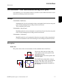
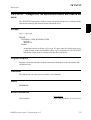
AccSet - Reduces the acceleration
AccSet is used when handling fragile loads. It allows slower acceleration and deceleration, which results in smoother robot movements.
Examples
AccSet 50, 100;
The acceleration is limited to 50% of the normal value.
AccSet 100, 50;
The acceleration ramp is limited to 50% of the normal value.
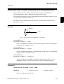
Arguments
AccSet
Acc Ramp
Acc
Data type: num
Acceleration and deceleration as a percentage of the normal values.
100% corresponds to maximum acceleration. Maximum value: 100%.
Input value < 20% gives 20% of maximum acceleration.
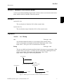
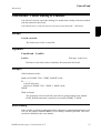
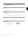
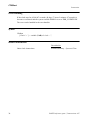
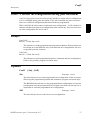
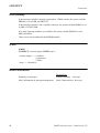
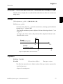
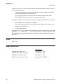
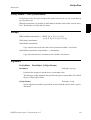
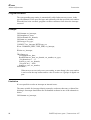
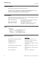
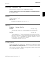
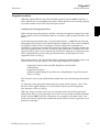
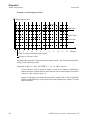
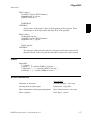
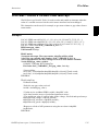
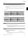
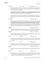
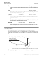
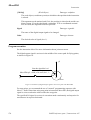
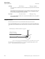
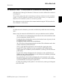
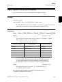
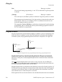
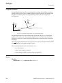
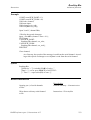
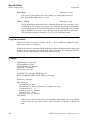
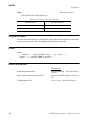
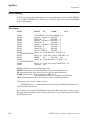
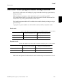
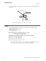
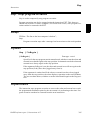
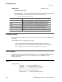
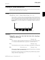
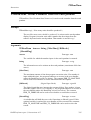
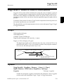
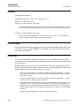
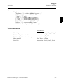
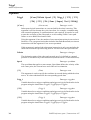
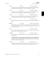
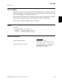
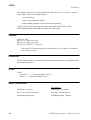
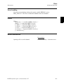
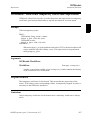
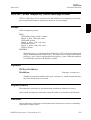
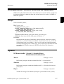
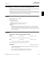
Ramp
Data type: num
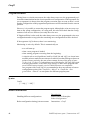
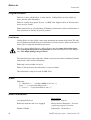
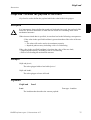
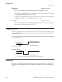
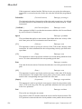
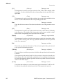
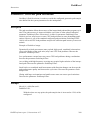
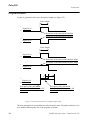
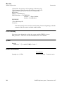
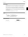
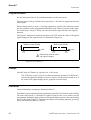
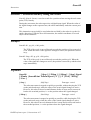
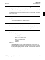
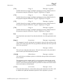
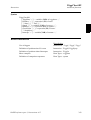
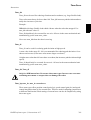
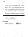
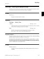
The rate at which acceleration and deceleration increases as a percentage of the
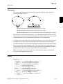
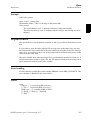
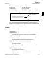
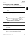
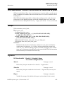
normal values (see Figure 1). Jerking can be restricted by reducing this value.
100% corresponds to maximum rate. Maximum value: 100%.
Input value < 10% gives 10% of maximum rate.
Acceleration
Time
AccSet 100, 100, i.e. normal acceleration
Acceleration
Acceleration
Time
Time
AccSet 30, 100
AccSet 100, 30
Figure 1 Reducing the acceleration results in smoother movements.
RAPID reference part 1, Instructions A-Z
1
AccSet
Instruction
Program execution
The acceleration applies to both the robot and external axes until a new AccSet instruction is executed.
The default values (100%) are automatically set
- at a cold start-up
- when a new program is loaded
- when starting program executing from the beginning.
Syntax
AccSet
[ Acc ’:=’ ] < expression (IN) of num > ’,’
[ Ramp ’:=’ ] < expression (IN) of num > ’;’
Related information
Described in:
Positioning instructions
2
RAPID Summary - Motion
RAPID reference part 1, Instructions A-Z
ActUnit
Instruction
ActUnit - Activates a mechanical unit
ActUnit is used to activate a mechanical unit.
It can be used to determine which unit is to be active when, for example, common drive
units are used.
Example
ActUnit orbit_a;
Activation of the orbit_a mechanical unit.
Arguments
ActUnit MechUnit
MechUnit
(Mechanical Unit)
Data type: mecunit
The name of the mechanical unit that is to be activated.
Program execution
When the robot and external axes have come to a standstill, the specified mechanical
unit is activated. This means that it is controlled and monitored by the robot.
If several mechanical units share a common drive unit, activation of one of these
mechanical units will also connect that unit to the common drive unit.
Limitations
Instruction ActUnit cannot be used in
- program sequence StorePath ... RestoPath
- event routine RESTART
If this instruction is preceded by a move instruction, that move instruction must be programmed with a stop point (zonedata fine), not a fly-by point, otherwise restart after
power failure will not be possible.
RAPID reference part 1, Instructions A-Z
3
ActUnit
Instruction
Syntax
ActUnit
[MechUnit ’:=’ ] < variable (VAR) of mecunit> ’;’
Related information
Described in:
4
Deactivating mechanical units
Instructions - DeactUnit
Mechanical units
Data Types - mecunit
More examples
Instructions - DeactUnit
RAPID reference part 1, Instructions A-Z
Add
Instruction
Add - Adds a numeric value
Add is used to add or subtract a value to or from a numeric variable or persistent.
Examples
Add reg1, 3;
3 is added to reg1, i.e. reg1:=reg1+3.
Add reg1, -reg2;
The value of reg2 is subtracted from reg1, i.e. reg1:=reg1-reg2.
Arguments
Add
Name AddValue
Name
Data type: num
The name of the variable or persistent to be changed.
AddValue
Data type: num
The value to be added.
Syntax
Add
[ Name ’:=’ ] < var or pers (INOUT) of num > ’,’
[ AddValue ’:=’ ] < expression (IN) of num > ’;’
Related information
Described in:
Incrementing a variable by 1
Instructions - Incr
Decrementing a variable by 1
Instructions - Decr
Changing data using an arbitrary
expression, e.g. multiplication
Instructions - :=
RAPID reference part 1, Instructions A-Z
5
Add
Instruction
6
RAPID reference part 1, Instructions A-Z
“:=”
Instruction
“:=” - Assigns a value
The “:=” instruction is used to assign a new value to data. This value can be anything
from a constant value to an arithmetic expression, e.g. reg1+5*reg3.
Examples
reg1 := 5;
reg1 is assigned the value 5.
reg1 := reg2 - reg3;
reg1 is assigned the value that the reg2-reg3 calculation returns.
counter := counter + 1;
counter is incremented by one.
Arguments
Data := Value
Data
Data type: All
The data that is to be assigned a new value.
Value
Data type: Same as Data
The desired value.
Examples
tool1.tframe.trans.x := tool1.tframe.trans.x + 20;
The TCP for tool1 is shifted 20 mm in the X-direction.
pallet{5,8} := Abs(value);
An element in the pallet matrix is assigned a value equal to the absolute value of
the value variable.
RAPID reference part 1, Instructions A-Z
7
“:=”
Instruction
Limitations
The data (whose value is to be changed) must not be
- a constant
- a non-value data type.
The data and value must have similar (the same or alias) data types.
Syntax
(EBNF)
<assignment target> ’:=’ <expression> ’;’
<assignment target> ::=
<variable>
| <persistent>
| <parameter>
| <VAR>
Related information
Described in:
8
Expressions
Basic Characteristics - Expressions
Non-value data types
Basic Characteristics - Data Types
Assigning an initial value to data
Basic Characteristics - Data
Programming and Testing
Manually assigning a value to data
Programming and Testing
RAPID reference part 1, Instructions A-Z
Break
Instruction
Break - Break program execution
Break is used to make an immediate break in program execution for RAPID program
code debugging purposes.
Example
..
Break;
...
Program execution stops and it is possible to analyse variables, values etc. for
debugging purposes.
Program execution
The instruction stops program execution at once, without waiting for the robot and
external axes to reach their programmed destination points for the movement being
performed at the time. Program execution can then be restarted from the next instruction.
If there is a Break instruction in some event routine, the routine will be executed from
the beginning of the next event.
Syntax
Break’;’
Related information
Described in:
Stopping for program actions
Instructions - Stop
Stopping after a fatal error
Instructions - EXIT
Terminating program execution
Instructions - EXIT
Only stopping robot movements
Instructions - StopMove
RAPID reference part 1, Instructions A-Z
9
Break
Instruction
10
RAPID reference part 1, Instructions A-Z
CallByVar
Instruction
CallByVar - Call a procedure by a variable
CallByVar (Call By Variable) can be used to call procedures with specific names, e.g.
proc_name1, proc_name2, proc_name3 ... proc_namex via a variable.
Example
reg1 := 2;
CallByVar “proc”, reg1;
The procedure proc2 is called.
Arguments
CallByVar Name Number
Name
Data type: string
The first part of the procedure name, e.g. proc_name.
Number
Data type: num
The numeric value for the number of the procedure. This value will be converted
to a string and gives the 2:nd part of the procedure name e.g. 1. The value must
be a positive integer.
Example
Static selection of procedure call
TEST reg1
CASE 1:
lf_door door_loc;
CASE 2:
rf_door door_loc;
CASE 3:
lr_door door_loc;
CASE 4:
rr_door door_loc;
DEFAULT:
EXIT;
ENDTEST
Depending on whether the value of register reg1 is 1, 2, 3 or 4, different procedures are called that perform the appropriate type of work for the selected door.
The door location in argument door_loc.
RAPID reference part 1, Instructions A-Z
11
CallByVar
Instruction
Dynamic selection of procedure call with RAPID syntax
reg1 := 2;
%”proc”+NumToStr(reg1,0)% door_loc;
The procedure proc2 is called with argument door_loc.
Limitation: All procedures must have a specific name e.g. proc1, proc2, proc3.
Dynamic selection of procedure call with CallByVar
reg1 := 2;
CallByVar “proc”,reg1;
The procedure proc2 is called.
Limitation: All procedures must have specific name, e.g. proc1, proc2, proc3,
and no arguments can be used.
Limitations
Can only be used to call procedures without parameters.
Execution of CallByVar takes a little more time than execution of a normal procedure
call.
Error handling
In the event of a reference to an unknown procedure, the system variable ERRNO is set
to ERR_REFUNKPRC.
In the event of the procedure call error (not procedure), the system variable ERRNO is
set to ERR_CALLPROC.
These errors can be handled in the error handler.
Syntax
CallByVar
[Name ‘:=’] <expression (IN) of string>’,’
[Number ‘:=‘] <expression (IN) of num>’;’
12
RAPID reference part 1, Instructions A-Z
CallByVar
Instruction
Related information
Described in:
Calling procedures
RAPID reference part 1, Instructions A-Z
Basic Characteristic - Routines
User’s Guide - The programming
language RAPID
13
CallByVar
Instruction
14
RAPID reference part 1, Instructions A-Z
CancelLoad
Instruction
CancelLoad - Cancel loading of a module
CancelLoad is used to cancel the loading of a module that is being or has been loaded
with the instruction StartLoad.
CancelLoad can be used only between the instruction Startload ... WaitLoad.
Example
CancelLoad load1;
The load session load1 is cancelled.
Arguments
CancelLoad
LoadNo
LoadNo
Data type: loadsession
Reference to the load session, fetched by the instruction StartLoad.
Examples
VAR loadsession load1;
StartLoad “HOME:”\File:=”PART_B.MOD”,load1;
...
IF .................
CancelLoad load1;
StartLoad “HOME:”\File:=”PART_C.MOD”,load1;
ENDIF
...
WaitLoad load1;
The instruction CancelLoad will cancel the on-going loading of the module
PART_B.MOD and make it possible to in stead load PART_C.MOD.
Error handling
If the variable specified in argument LoadNo is not in use, meaning that no load session
is in use, the system variable ERRNO is set to ERR_LOADNO_NOUSE. This error
can then be handled in the error handler.
RAPID reference part 1, Instructions A-Z
15
CancelLoad
Instruction
Syntax
CancelLoad
[ LoadNo ’:=’ ] < variable (VAR) of loadsession > ’;’
Related information
Described in:
16
Load a program module during execution
Instructions - StartLoad
Connect the loaded module to the task
Instructions - WaitLoad
Load session
Data Types - loadsession
Load a program module
Instructions - Load
Unload a program module
Instructions - UnLoad
Accept unsolved references
System Parameters - Controller/Task/
BindRef
RAPID reference part 1, Instructions A-Z
CirPathMode
Instruction
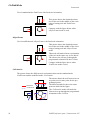
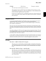
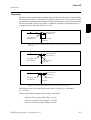
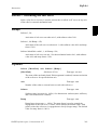
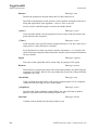
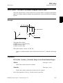
CirPathMode - Tool reorientation during circle path
CirPathMode (Circle Path Mode) makes it possible to select different modes to reorientate the tool during circular movements.
Example
CirPathMode \PathFrame;
Standard mode for tool reorientation in the actual path frame from the start point
to the ToPoint during all succeeding circular movements.
This is default in the system.
CirPathMode \ObjectFrame;
Modified mode for tool reorientation in actual object frame from the start point
to the ToPoint during all succeeding circular movements.
CirPathMode \CirPointOri;
Modified mode for tool reorientation from the start point via the programmed
CirPoint orientation to the ToPoint during all succeeding circular movements.
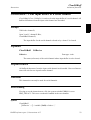
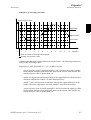
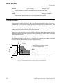
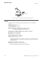
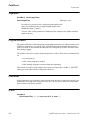
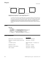
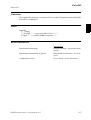
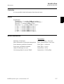
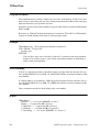
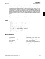
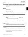
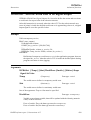
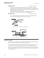
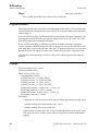
Description
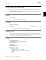
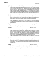
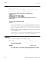
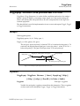
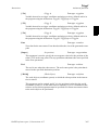
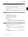
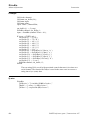
PathFrame
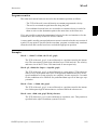
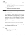
The picture shows the tool reorientation for the standard mode \PathFrame.
The arrows shows the tool from wrist
centre point to tool centre point for the
programmed points.
The path for the wrist centre point is dotted in the figure.
The \PathFrame mode make it easy to
get the same angle of the tool around the
cylinder. The robot wrist will not go
through the programmed orientation in
the CirPoint.
RAPID reference part 1, Instructions A-Z
17
CirPathMode
Instruction
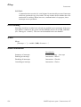
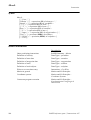
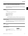
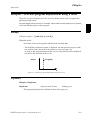
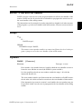
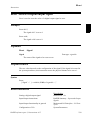
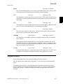
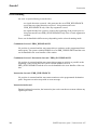
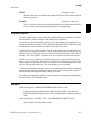
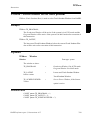
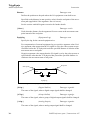
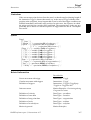
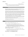
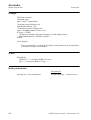
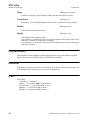
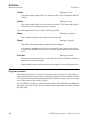
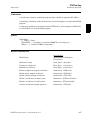
Use of standard mode \PathFrame with fixed tool orientation:
This picture shows the obtained orientation of the tool in the middle of the circle
using a leaning tool and \PathFrame
mode.
Compare with the figure below when
\ObjectFrame mode is used
ObjectFrame
Use of modified mode \ObjectFrame with fixed tool orientation:
This picture shows the obtained orientation of the tool in the middle of the circle
using a leaning tool and \ObjectFrame
mode.
This mode will make a linear reorientation
of the tool in the same way as for MoveL.
The robot wrist will not go through the
programmed orientation in the CirPoint.
Compare with the figure above when
\PathFrame mode is used
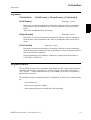
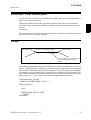
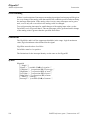
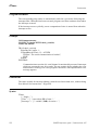
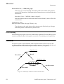
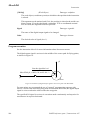
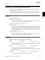
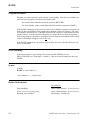
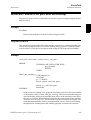
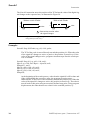
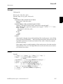
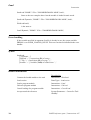
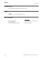
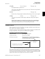
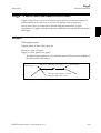
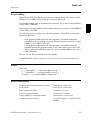
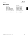
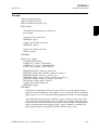
CirPointOri
The picture shows the different tool reorientation between the standard mode
\PathFrame and the modified mode \CirPointOri.
\Pathframe
\CirPointOri
The arrows shows the tool from wrist centre point to tool centre point for the programmed points.
The different paths for the wrist centre
point are dotted in the figure.
The \CirPointOri mode will make the
robot wrist to go through the programmed
orientation in the CirPoint.
18
RAPID reference part 1, Instructions A-Z
CirPathMode
Instruction
Arguments
CirPathMode
[\PathFrame] | [\ObjectFrame] | [\CirPointOri]
[\PathFrame]
Data type: switch
During the circular movement the reorientaion of the tool is done continuous
from the start point orientation to the ToPoint orientation in the actual path
frame.
This is the standard mode in the system.
[\ObjectFrame]
Data type: switch
During the circular movement the reorientaion of the tool is done continuous
from the start point orientation to the ToPoint orientation in the actual object
frame.
[\CirPointOri]
Data type: switch
During the circular movement the reorientaion of the tool is done continuous
from the start point orientation to the programmed CirPoint orientation and further to the ToPoint orientation.
Only programming CirPathMode; without any switch result in the same as
CirPointOri \PathFrame;
Program execution
The specified circular tool reorientation mode applies for the next executed robot circular movements of any type (MoveC, SearchC, TriggC, MoveCDO, MoveCSync,
ArcC, PaintC ... ) and is valid until a new CirPathMode (or obsolete CirPathReori)
instruction is executed.
The standard circular reorientation mode (CirPathMode \PathFrame) is automatically
set
- at a cold start-up
- when a new program is loaded
- when starting program executing from the beginning.
RAPID reference part 1, Instructions A-Z
19
CirPathMode
Instruction
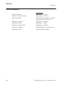
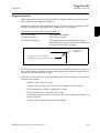
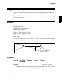
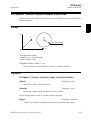
Limitations
The instruction only affects circular movements.
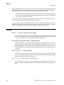
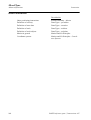
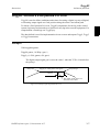
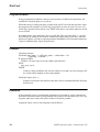
When using the \CirPointOri mode, the CirPoint must be between the points
A and B according to the figure below to make the circle movement to go through
the programmed orientation in the CirPoint.
1 /4
A 1 /4
1 /4 B
1 /4
CirPoint
If working in wrist singularity area and the instruction SingArea \Wrist has been executed, the instruction CirPathMode has no effect because the system then select
another tool reorientation mode for circular movements (joint interpolation).
This instruction replace the old instruction CirPathReori
(will work even in future but will not be documented any more).
Syntax
CirPathMode
[‘\’PathFrame] | [‘\’ObjectFrame] | [‘\’CirPointOri] ‘;’
Related information
Described in:
20
Interpolation
Program Execution
Motion Principles - Positioning during
Motion settings data
Data Types - motsetdata
Circular move instruction
Instructions - MoveC
RAPID reference part 1, Instructions A-Z
Clear
Instruction
Clear - Clears the value
Clear is used to clear a numeric variable or persistent , i.e. it sets it to 0.
Example
Clear reg1;
Reg1 is cleared, i.e. reg1:=0.
Arguments
Clear
Name
Name
Data type: num
The name of the variable or persistent to be cleared.
Syntax
Clear
[ Name ’:=’ ] < var or pers (INOUT) of num > ’;’
Related information
Described in:
Incrementing a variable by 1
Instructions - Incr
Decrementing a variable by 1
Instructions - Decr
RAPID reference part 1, Instructions A-Z
21
Clear
Instruction
22
RAPID reference part 1, Instructions A-Z
ClearIOBuff
Instruction
Advanced functions
ClearIOBuff - Clear input buffer of a serial channel
ClearIOBuff (Clear I/O Buffer) is used to clear the input buffer of a serial channel. All
buffered characters from the input serial channel are discarded.
Example
VAR iodev channel2;
...
Open "com2:", channel2 \Bin;
ClearIOBuff channel2;
The input buffer for the serial channel referred to by channel2 is cleared.
Arguments
ClearIOBuff
IODevice
IODevice
Data type: iodev
The name (reference) of the serial channel whose input buffer is to be cleared.
Program execution
All buffered characters from the input serial channel are discarded. Next read instructions will wait for new input from the channel.
Limitations
This instruction can only be used for serial channels.
Error handling
If trying to use the instruction on a file, the system variable ERRNO is set to
ERR_FILEACC. This error can then be handled in the error handler.
Syntax
ClearIOBuff
[IODevice ’:=’] <variable (VAR) of iodev>’;’
RAPID reference part 1, Instructions A-Z
23
ClearIOBuff
Advanced functions
Instruction
Related information
Described in:
Opening a serial channel
24
RAPID Summary - Communication
RAPID reference part 1, Instructions A-Z
ClearPath
Instruction
ClearPath - Clear current path
ClearPath (Clear Path) clear the whole motion path on the current motion path level
(base level or StorePath level).
With motion path means all the movement segments from any move instructions
which has been executed in RAPID but not performed by the robot at the execution
time of
ClearPath.
The robot must be in a stop point position or must be stopped by StopMove before the
instruction ClearPath can be executed.
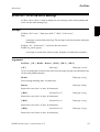
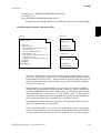
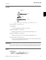
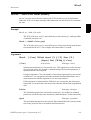
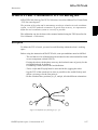
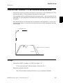
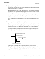
Example
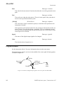
Start point home
MoveL p1, v500, fine, gripper;
End point p1
px
The robot drops its payload here and
execution continues in the trap
routine
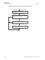
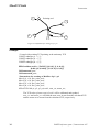
In the following program example, the robot moves from the position home to the position p1. At the point px the signal di1 will indicate that the payload has been dropped.
The execution continues in the trap routine gohome. The robot will stop moving (start
the braking) at px, the path will be cleared, the robot will move to position home. The
error will be raised up to the calling routine minicycle and the whole user defined program cycle proc1 .. proc2 will be executed from beginning one more time.
VAR intnum drop_payload;
CONST errnum ERR_DROP_LOAD := 1;
PROC minicycle()
..........
proc1;
..........
ERROR (ERR_DROP_LOAD)
RETRY;
ENDPROC
RAPID reference part 1, Instructions A-Z
25
ClearPath
Instruction
PROC proc1()
..........
proc2;
..........
ENDPROC
PROC proc2()
CONNECT drop_payload WITH gohome;
ISignalDI \Single, di1, 1, drop_payload;
MoveL p1, v500, fine, gripper;
...........
IDelete drop_payload
ENDPROC
TRAP gohome
StopMove \Quick;
ClearPath;
IDelete drop_payload;
MoveL home, v500, fine, gripper;
RAISE ERR_DROP_LOAD;
ERROR
RAISE;
ENDTRAP
If the same program is being run but without StopMove and ClearPath in the
trap routine gohome, the robot will continue to position p1 before going back to
position home.
If programming MoveL home with flying-point (zone) instead of stop-point
(fine), the movement is going on during the RAISE to the error handler in procedure minicycle and further until the movement is ready.
Syntax
ClearPath ’;’
Related information
Described in:
26
Stop robot movements
Instructions - StopMove
Error recovery
RAPID Summary - Error Recovery
Basic Characteristics - Error Recovery
RAPID reference part 1, Instructions A-Z
ClkReset
Instruction
ClkReset - Resets a clock used for timing
ClkReset is used to reset a clock that functions as a stop-watch used for timing.
This instruction can be used before using a clock to make sure that it is set to 0.
Example
ClkReset clock1;
The clock clock1 is reset.
Arguments
ClkReset
Clock
Clock
Data type: clock
The name of the clock to reset.
Program execution
When a clock is reset, it is set to 0.
If a clock is running, it will be stopped and then reset.
Syntax
ClkReset
[ Clock ’:=’ ] < variable (VAR) of clock > ’;’
Related information
Described in:
Other clock instructions
RAPID reference part 1, Instructions A-Z
RAPID Summary - System & Time
27
ClkReset
Instruction
28
RAPID reference part 1, Instructions A-Z
ClkStart
Instruction
ClkStart - Starts a clock used for timing
ClkStart is used to start a clock that functions as a stop-watch used for timing.
Example
ClkStart clock1;
The clock clock1 is started.
Arguments
ClkStart
Clock
Clock
Data type: clock
The name of the clock to start.
Program execution
When a clock is started, it will run and continue counting seconds until it is stopped.
A clock continues to run when the program that started it is stopped. However, the
event that you intended to time may no longer be valid. For example, if the program
was measuring the waiting time for an input, the input may have been received while
the program was stopped. In this case, the program will not be able to “see” the event
that occurred while the program was stopped.
A clock continues to run when the robot is powered down as long as the battery backup retains the program that contains the clock variable.
If a clock is running it can be read, stopped or reset.
Example
VAR clock clock2;
ClkReset clock2;
ClkStart clock2;
WaitUntil DInput(di1) = 1;
ClkStop clock2;
time:=ClkRead(clock2);
The waiting time for di1 to become 1 is measured.
RAPID reference part 1, Instructions A-Z
29
ClkStart
Instruction
Error handling
If the clock runs for 4,294,967 seconds (49 days 17 hours 2 minutes 47 seconds) it
becomes overflowed and the system variable ERRNO is set to ERR_OVERFLOW.
The error can be handled in the error handler.
Syntax
ClkStart
[ Clock ’:=’ ] < variable (VAR) of clock > ’;’
Related information
Described in:
Other clock instructions
30
RAPID Summary - System & Time
RAPID reference part 1, Instructions A-Z
ClkStop
Instruction
ClkStop - Stops a clock used for timing
ClkStop is used to stop a clock that functions as a stop-watch used for timing.
Example
ClkStop clock1;
The clock clock1 is stopped.
Arguments
ClkStop
Clock
Clock
Data type: clock
The name of the clock to stop.
Program execution
When a clock is stopped, it will stop running.
If a clock is stopped, it can be read, started again or reset.
Error handling
If the clock runs for 4,294,967 seconds (49 days 17 hours 2 minutes 47 seconds) it
becomes overflowed and the system variable ERRNO is set to ERR_OVERFLOW.
The error can be handled in the error handler.
Syntax
ClkStop
[ Clock ’:=’ ] < variable (VAR) of clock > ’;’
RAPID reference part 1, Instructions A-Z
31
ClkStop
Instruction
Related Information
Described in:
32
Other clock instructions
RAPID Summary - System & Time
More examples
Instructions - ClkStart
RAPID reference part 1, Instructions A-Z
comment
Instruction
comment - Comment
Comment is only used to make the program easier to understand. It has no effect on the
execution of the program.
Example
! Goto the position above pallet
MoveL p100, v500, z20, tool1;
A comment is inserted into the program to make it easier to understand.
Arguments
! Comment
Comment
Text string
Any text.
Program execution
Nothing happens when you execute this instruction.
Syntax
(EBNF)
’!’ {<character>} <newline>
Related information
Described in:
Characters permitted in a comment
Basic CharacteristicsBasic Elements
Comments within data and routine
declarations
Basic CharacteristicsBasic Elements
RAPID reference part 1, Instructions A-Z
33
comment
Instruction
34
RAPID reference part 1, Instructions A-Z
Compact IF
Instruction
Compact IF - If a condition is met, then... (one instruction)
Compact IF is used when a single instruction is only to be executed if a given condition
is met.
If different instructions are to be executed, depending on whether the specified
condition is met or not, the IF instruction is used.
Examples
IF reg1 > 5 GOTO next;
If reg1 is greater than 5, program execution continues at the next label.
IF counter > 10 Set do1;
The do1 signal is set if counter > 10.
Arguments
IF
Condition
...
Condition
Data type: bool
The condition that must be satisfied for the instruction to be executed.
Syntax
(EBNF)
IF <conditional expression> ( <instruction> | <SMT>) ’;’
Related information
Described in:
Conditions (logical expressions)
Basic Characteristics - Expressions
IF with several instructions
Instructions - IF
RAPID reference part 1, Instructions A-Z
35
Compact IF
Instruction
36
RAPID reference part 1, Instructions A-Z
ConfJ
Instruction
ConfJ - Controls the configuration during joint movement
ConfJ (Configuration Joint) is used to specify whether or not the robot’s configuration
is to be controlled during joint movement. If it is not controlled, the robot can sometimes use a different configuration than that which was programmed.
With ConfJ\Off, the robot cannot switch main axes configuration - it will search for a
solution with the same main axes configuration as the current one. It moves to the closest wrist configuration for axes 4 and 6.
Examples
ConfJ \Off;
MoveJ *, v1000, fine, tool1;
The robot moves to the programmed position and orientation. If this position can
be reached in several different ways, with different axis configurations, the closest possible position is chosen.
ConfJ \On;
MoveJ *, v1000, fine, tool1;
The robot moves to the programmed position, orientation and axis configuration.
If this is not possible, program execution stops.
Arguments
ConfJ
[\On] | [\Off]
\On
Data type: switch
The robot always moves to the programmed axis configuration. If this is not possible using the programmed position and orientation, program execution stops.
The IRB5400 robot will move to the programmed axis configuration or to an axis
configuration close the programmed one. Program execution will not stop if it is
impossible to reach the programmed axis configuration.
\Off
Data type: switch
The robot always moves to the closest axis configuration.
RAPID reference part 1, Instructions A-Z
37
ConfJ
Instruction
Program execution
If the argument \On (or no argument) is chosen, the robot always moves to the programmed axis configuration. If this is not possible using the programmed position and
orientation, program execution stops before the movement starts.
If the argument \Off is chosen, the robot always moves to the closest axis configuration.
This may be different to the programmed one if the configuration has been incorrectly
specified manually, or if a program displacement has been carried out.
The control is active by default. This is automatically set
- at a cold start-up
- when a new program is loaded
- when starting program executing from the beginning.
Syntax
ConfJ
[ ’\’ On] | [ ’\’ Off] ’;’
Related information
Described in:
Handling different configurations
Motion Principles Robot Configuration
Robot configuration during linear movement Instructions - ConfL
38
RAPID reference part 1, Instructions A-Z
ConfL
Instruction
ConfL - Monitors the configuration during linear movement
ConfL (Configuration Linear) is used to specify whether or not the robot’s configuration is to be monitored during linear or circular movement. If it is not monitored, the
configuration at execution time may differ from that at programmed time. It may also
result in unexpected sweeping robot movements when the mode is changed to joint
movement.
NOTE: For the IRB 5400 robot the monotoring is always off independent of what
is specified in ConfL.
Examples
ConfL \On;
MoveL *, v1000, fine, tool1;
Program execution stops when the programmed configuration is not possible to
reach from the current position.
SingArea \Wrist;
ConfL \On;
MoveL *, v1000, fine, tool1;
The robot moves to the programmed position, orientation and wrist axis configuration. If this is not possible, program execution stops.
ConfL \Off;
MoveL *, v1000, fine, tool1;
The robot moves to the programmed position and orientation, but to the closest
possible axis configuration, which can be different from the programmed.
Arguments
ConfL
[\On] | [\Off]
\On
Data type: switch
The robot configuration is monitored.
\Off
Data type: switch
The robot configuration is not monitored.
RAPID reference part 1, Instructions A-Z
39
ConfL
Instruction
Program execution
During linear or circular movement, the robot always moves to the programmed position and orientation that has the closest possible axis configuration. If the argument \On
(or no argument) is chosen, then the program execution stops as soon as there’s a risk
that the configuration of the programmed position not will be attained from the current
position.
However, it is possible to restart the program again, although the wrist axes may continue to the wrong configuration. At a stop point, the robot will check that the configurations of all axes are achieved, not only the wrist axes.
If SingArea\Wrist is also used, the robot always moves to the programmed wrist axes
configuration and at a stop point the remaining axes configurations will be checked.
If the argument \Off is chosen, there is no monitoring.
Monitoring is active by default. This is automatically set
- at a cold start-up
- when a new program is loaded
- when starting program executing from the beginning.
- A simple rule to avoid problems, both for ConfL\On and \Off, is to insert intermediate points to make the movement of each axis less than 90 degrees between
points or more precisely, the sum of movements for any of the pairs of axes
(1+4), (1+6), (3+4) or (3+6) should not exceed 180 degrees. If ConfL\Off is used
with a big movement, it can cause stops directly or later in the program with
error 50050 Position outside reach or 50080 Position not compatible.
In a program with ConfL\Off it’s recommended to have movements to known
configurations points with “ConfJ\On + MoveJ” or “ConfL\On + SingArea\Wrist + MoveL” as start points for different program parts.
Syntax
ConfL
[ ’\’ On] | [ ’\’ Off] ’;’
Related information
Described in:
40
Handling different configurations
Motion and I/O PrinciplesRobot Configuration
Robot configuration during joint movement
Instructions - ConfJ
RAPID reference part 1, Instructions A-Z
Close
Instruction
Advanced functions
Close - Closes a file or serial channel
Close is used to close a file or serial channel.
Example
Close channel2;
The serial channel referred to by channel2 is closed.
Arguments
Close
IODevice
IODevice
Data type: iodev
The name (reference) of the file or serial channel to be closed.
Program execution
The specified file or serial channel is closed and must be re-opened before reading or
writing. If it is already closed, the instruction is ignored.
Syntax
Close
[IODevice ’:=’] <variable (VAR) of iodev>’;’
Related information
Described in:
Opening a file or serial channel
RAPID reference part 1, Instructions A-Z
RAPID Summary - Communication
41
Close
Advanced functions
42
Instruction
RAPID reference part 1, Instructions A-Z
CONNECT
Instruction
CONNECT - Connects an interrupt to a trap routine
CONNECT is used to find the identity of an interrupt and connect it to a trap routine.
The interrupt is defined by ordering an interrupt event and specifying its identity. Thus,
when that event occurs, the trap routine is automatically executed.
Example
VAR intnum feeder_low;
CONNECT feeder_low WITH feeder_empty;
ISignalDI di1, 1 , feeder_low;
An interrupt identity feeder_low is created which is connected to the trap routine
feeder_empty. The interrupt is defined as input di1 is getting high. In other
words, when this signal becomes high, the feeder_empty trap routine is executed.
Arguments
CONNECT Interrupt WITH Trap routine
Interrupt
Data type: intnum
The variable that is to be assigned the identity of the interrupt.
This must not be declared within a routine (routine data).
Trap routine
Identifier
The name of the trap routine.
Program execution
The variable is assigned an interrupt identity which can then be used when ordering or
disabling interrupts. This identity is also connected to the specified trap routine.
Note that before an event can be handled, an interrupt must also be ordered, i.e. the
event specified.
Limitations
An interrupt (interrupt identity) cannot be connected to more than one trap routine. Different interrupts, however, can be connected to the same trap routine.
When an interrupt has been connected to a trap routine, it cannot be reconnected or
transferred to another routine; it must first be deleted using the instruction IDelete.
RAPID reference part 1, Instructions A-Z
43
CONNECT
Instruction
Error handling
If the interrupt variable is already connected to a TRAP routine, the system variable
ERRNO is set to ERR_ALRDYCNT.
If the interrupt variable is not a variable reference, the system variable ERRNO is set
to ERR_CNTNOTVAR.
If no more interrupt numbers are available, the system variable ERRNO is set to
ERR_INOMAX.
These errors can be handled in the ERROR handler.
Syntax
(EBNF)
CONNECT <connect target> WITH <trap>‘;’
<connect target> ::= <variable>
| <parameter>
| <VAR>
<trap> ::= <identifier>
Related information
Described in:
44
Summary of interrupts
RAPID Summary - Interrupts
More information on interrupt management
Basic Characteristics- Interrupts
RAPID reference part 1, Instructions A-Z
DeactUnit
Instruction
DeactUnit - Deactivates a mechanical unit
DeactUnit is used to deactivate a mechanical unit.
It can be used to determine which unit is to be active when, for example, common drive
units are used.
Examples
DeactUnit orbit_a;
Deactivation of the orbit_a mechanical unit.
MoveL p10, v100, fine, tool1;
DeactUnit track_motion;
MoveL p20, v100, z10, tool1;
MoveL p30, v100, fine, tool1;
ActUnit track_motion;
MoveL p40, v100, z10, tool1;
The unit track_motion will be stationary when the robot moves to p20 and p30.
After this, both the robot and track_motion will move to p40.
MoveL p10, v100, fine, tool1;
DeactUnit orbit1;
ActUnit orbit2;
MoveL p20, v100, z10, tool1;
The unit orbit1 is deactivated and orbit2 activated.
Arguments
DeactUnit MechUnit
MechUnit
(Mechanical Unit)
Data type: mecunit
The name of the mechanical unit that is to be deactivated.
Program execution
When the robot and external axes have come to a standstill, the specified mechanical
unit is deactivated. This means that it will neither be controlled nor monitored until it
is re-activated.
If several mechanical units share a common drive unit, deactivation of one of the
mechanical units will also disconnect that unit from the common drive unit.
RAPID reference part 1, Instructions A-Z
45
DeactUnit
Instruction
Limitations
Instruction DeactUnit cannot be used
- in program sequence StorePath ... RestoPath
- in event routine RESTART
- when one of the axes in the mechanical unit is in independent mode.
If this instruction is preceded by a move instruction, that move instruction must be programmed with a stop point (zonedata fine), not a fly-by point, otherwise restart after
power failure will not be possible.
Syntax
DeactUnit
[MechUnit ’:=’ ] < variable (VAR) of mecunit> ’;’
Related information
Described in:
46
Activating mechanical units
Instructions - ActUnit
Mechanical units
Data Types - mecunit
RAPID reference part 1, Instructions A-Z
Decr
Instruction
Decr - Decrements by 1
Decr is used to subtract 1 from a numeric variable or persistent.
Example
Decr reg1;
1 is subtracted from reg1, i.e. reg1:=reg1-1.
Arguments
Decr
Name
Name
Data type: num
The name of the variable or persistent to be decremented.
Example
TPReadNum no_of_parts, "How many parts should be produced? ";
WHILE no_of_parts>0 DO
produce_part;
Decr no_of_parts;
ENDWHILE
The operator is asked to input the number of parts to be produced. The variable
no_of_parts is used to count the number that still have to be produced.
Syntax
Decr
[ Name ’:=’ ] < var or pers (INOUT) of num > ’;’
RAPID reference part 1, Instructions A-Z
47
Decr
Instruction
Related information
Described in:
48
Incrementing a variable by 1
Instructions - Incr
Subtracting any value from a variable
Instructions - Add
Changing data using an arbitrary
expression, e.g. multiplication
Instructions - :=
RAPID reference part 1, Instructions A-Z
DitherAct
Instruction
DitherAct - Enables dither for soft servo
DitherAct is used to enable the dither functionality, which will reduce the friction in
soft servo for IRB 7600.
Examples
SoftAct \MechUnit:=IRB, 2, 100;
WaitTime 2;
DitherAct \MechUnit:=IRB, 2;
WaitTime 1;
DitherDeact;
SoftDeact;
Dither is enabled only for one second while in soft servo.
DitherAct \MechUnit:=IRB, 2;
SoftAct \MechUnit:=IRB, 2, 100;
WaitTime 1;
MoveL p1, v50, z20, tool1;
SoftDeact;
DitherDeact;
Dither is enabled for axis 2. Movement is delayed one second to allow sufficient
transition time for the SoftAct ramp. If DitherAct is called before SoftAct, dither
will start whenever a SoftAct is executed for that axis. If no DitherDeact is called,
dither will stay enabled for all subsequent SoftAct calls.
Arguments
DitherAct
[ \MechUnit ] Axis [ \Level ]
[ \MechUnit ]
(Mechanical Unit)
Data type: mecunit
The name of the mechanical unit. If argument is omitted, it means activation of
the soft servo for specified robot axis.
Axis
Data type: num
Axis number (1-6).
[ \Level ]
Data type: num
Amplitude of dither (50-150%). At 50%, oscillations are reduced (increased friction). At 150%, amplitude is maximum (may result in vibrations of endeffector).
The default value is 100%.
RAPID reference part 1, Instructions A-Z
49
DitherAct
Instruction
Program execution
DitherAct can be called before, or after SoftAct. Calling DitherAct after SoftAct is
faster, but has other limitations.
Dither is usually not required for axis 1 of IRB 7600. Highest effect of friction reduction is on axes 2 and 3.
Dither parameters are self-adjusting. Full dither performance is achieved after three or
four executions of SoftAct in process position.
Limitations
Calling DitherAct after SoftAct may cause unwanted movement of the robot.The only
way to eliminate this behaviour is to call DitherAct before SoftAct. If there still is movement, SoftAct ramp time should be increased.
However, when calling DitherAct before SoftAct the robot must be in a fine point.
Also, leaving the fine point is not permitted until the transition time of the ramp is
over. This might damage the gear boxes.
The transition time is the ramp time, which varies between robots, multiplied with the
ramp factor of the SoftAct-instruction.
Dithering is not available for axis 6.
Dither is always deactivated when there is a power failure.
The instruction is only to be used for IRB 7600.
Syntax
DitherAct
[ ’\’ MechUnit ’:=’ < variable (VAR) of mecunit > ]
[Axis ’:=’ ] < expression (IN) of num >
[ ’\’ Level ‘:=’ < expression (IN) of num > ] ’;’
Related information
Described in:
50
Activating Soft Servo
Instructions - SoftAct
Behaviour with the soft servo engaged
Motion and I/O Principles - Positioning during program execution
Disable of dither
Instructions - DitherDeact
RAPID reference part 1, Instructions A-Z
DitherDeact
Instruction
DitherDeact - Disables dither for soft servo
DitherDeact is used to disable the dither functionality for soft servo of IRB 7600.
Examples
DitherDeact;
Deactivates dither on all axis.
Program execution
DitherDeact can be used at any time. If in soft servo, dither stops immediatley on all
axis. If not in soft servo, dither will not be active when next SoftAct is executed.
Syntax
DitherDeact ‘;’
Related information
Described in:
Activating dither
RAPID reference part 1, Instructions A-Z
Instructions - DitherAct
51
DitherDeact
Instruction
52
RAPID reference part 1, Instructions A-Z
EOffsOff
Instruction
EOffsOff - Deactivates an offset for external axes
EOffsOff (External Offset Off) is used to deactivate an offset for external axes.
The offset for external axes is activated by the instruction EOffsSet or EOffsOn and
applies to all movements until some other offset for external axes is activated or until
the offset for external axes is deactivated.
Examples
EOffsOff;
Deactivation of the offset for external axes.
MoveL p10, v500, z10, tool1;
EOffsOn \ExeP:=p10, p11;
MoveL p20, v500, z10, tool1;
MoveL p30, v500, z10, tool1;
EOffsOff;
MoveL p40, v500, z10, tool1;
An offset is defined as the difference between the position of each axis at p10
and p11. This displacement affects the movement to p20 and p30, but not to p40.
Program execution
Active offsets for external axes are reset.
Syntax
EOffsOff ‘;’
Related information
Described in:
Definition of offset using two positions
Instructions - EOffsOn
Definition of offset using values
Instructions - EOffsSet
Deactivation of the robot’s motion displacementInstructions - PDispOff
RAPID reference part 1, Instructions A-Z
53
EOffsOff
Instruction
54
RAPID reference part 1, Instructions A-Z
EOffsOn
Instruction
EOffsOn - Activates an offset for external axes
EOffsOn (External Offset On) is used to define and activate an offset for external axes
using two positions.
Examples
MoveL p10, v500, z10, tool1;
EOffsOn \ExeP:=p10, p20;
Activation of an offset for external axes. This is calculated for each axis based
on the difference between positions p10 and p20.
MoveL p10, v500, fine \Inpos := inpos50, tool1;
EOffsOn *;
Activation of an offset for external axes. Since a stop point that is accurately
defined has been used in the previous instruction, the argument \ExeP does not
have to be used. The displacement is calculated on the basis of the difference
between the actual position of each axis and the programmed point (*) stored in
the instruction.
Arguments
EOffsOn [ \ExeP ] ProgPoint
[\ExeP ]
(Executed Point)
Data type: robtarget
The new position of the axes at the time of the program execution. If this argument is omitted, the current position of the axes at the time of the program execution is used.
ProgPoint
(Programmed Point)
Data type: robtarget
The original position of the axes at the time of programming.
Program execution
The offset is calculated as the difference between ExeP and ProgPoint for each separate external axis. If ExeP has not been specified, the current position of the axes at the
time of the program execution is used instead. Since it is the actual position of the axes
that is used, the axes should not move when EOffsOn is executed.
RAPID reference part 1, Instructions A-Z
55
EOffsOn
Instruction
This offset is then used to displace the position of external axes in subsequent positioning instructions and remains active until some other offset is activated (the instruction
EOffsSet or EOffsOn) or until the offset for external axes is deactivated (the instruction
EOffsOff).
Only one offset for each individual external axis can be activated at any one time. Several EOffsOn, on the other hand, can be programmed one after the other and, if they are,
the different offsets will be added.
The external axes’ offset is automatically reset
- at a cold start-up
- when a new program is loaded
- when starting program executing from the beginning.
Example
SearchL sen1, psearch, p10, v100, tool1;
PDispOn \ExeP:=psearch, *, tool1;
EOffsOn \ExeP:=psearch, *;
A search is carried out in which the searched position of both the robot and the
external axes is stored in the position psearch. Any movement carried out after
this starts from this position using a program displacement of both the robot and
the external axes. This is calculated based on the difference between the searched
position and the programmed point (*) stored in the instruction.
Syntax
EOffsOn
[ ‘\’ ExeP ’:=’ < expression (IN) of robtarget > ’,’]
[ ProgPoint ’:=’ ] < expression (IN) of robtarget > ’;’
Related information
Described in:
56
Deactivation of offset for external axes
Instructions - EOffsOff
Definition of offset using values
Instructions - EOffsSet
Displacement of the robot’s movements
Instructions - PDispOn
Coordinate Systems
Motion Principles- Coordinate Systems
RAPID reference part 1, Instructions A-Z
EOffsSet
Instruction
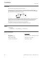
EOffsSet - Activates an offset for external axes using a value
EOffsSet (External Offset Set) is used to define and activate an offset for external axes
using values.
Example
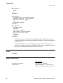
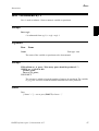
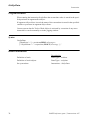
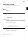
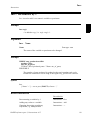
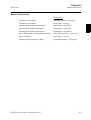
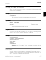
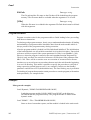
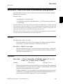
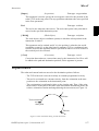
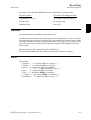
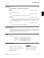
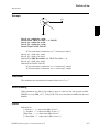
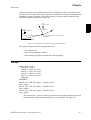
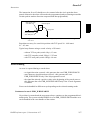
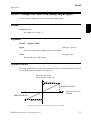
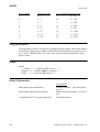
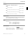
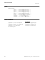
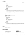
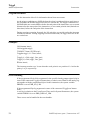
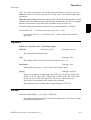
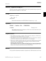
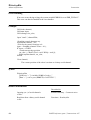
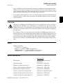
VAR extjoint eax_a_p100 := [100, 0, 0, 0, 0, 0];
.
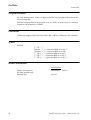
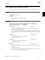
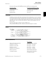
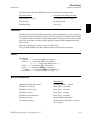
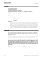
EOffsSet eax_a_p100;
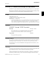
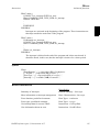
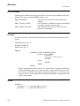
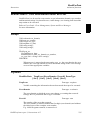
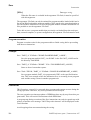
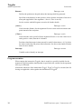
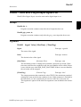
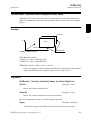
Activation of an offset eax_a_p100 for external axes, meaning (provided that the
external axis “a” is linear) that:
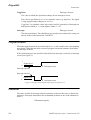
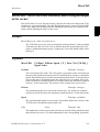
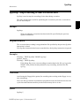
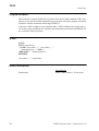
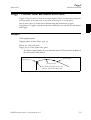
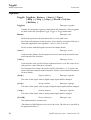
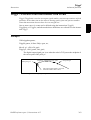
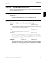
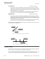
- The ExtOffs coordinate system is displaced 100 mm for the logical axis “a” (see
Figure 2).
- As long as this offset is active, all positions will be displaced 100 mm in the
direction of the x-axis.
.
100
Normal
Coordinate System
0
+X
ExtOffs
Coordinate System
0
+X
Figure 2 Displacement of an external axis.
Arguments
EOffsSet EAxOffs
EAxOffs
(External Axes Offset)
Data type: extjoint
The offset for external axes is defined as data of the type extjoint, expressed in:
- mm for linear axes
- degrees for rotating axes
RAPID reference part 1, Instructions A-Z
57
EOffsSet
Instruction
Program execution
The offset for external axes is activated when the EOffsSet instruction is activated and
remains active until some other offset is activated (the instruction EOffsSet or EOffsOn)
or until the offset for external axes is deactivated (the EOffsOff).
Only one offset for external axes can be activated at any one time. Offsets cannot be
added to one another using EOffsSet.
The external axes’ offset is automatically reset
- at a cold start-up
- when a new program is loaded
- when starting program executing from the beginning.
Syntax
EOffsSet
[ EAxOffs ’:=’ ] < expression (IN) of extjoint> ’;’
Related information
Described in:
58
Deactivation of offset for external axes
Instructions - EOffsOff
Definition of offset using two positions
Instructions - EOffsOn
Displacement of the robot’s movements
Instructions - PDispOn
Definition of data of the type extjoint
Data Types - extjoint
Coordinate Systems
Motion Principles- Coordinate Systems
RAPID reference part 1, Instructions A-Z
ErrWrite
Instruction
ErrWrite - Write an error message
ErrWrite (Error Write) is used to display an error message on the teach pendant and
write it in the robot message log.
Example
ErrWrite “PLC error”, “Fatal error in PLC” \RL2:=”Call service”;
Stop;
A message is stored in the robot log. The message is also shown on the teach pendant display.
ErrWrite \ W, “ Search error”, “No hit for the first search”;
RAISE try_search_again;
A message is stored in the robot log only. Program execution then continues.
Arguments
ErrWrite [ \W ] Header Reason [ \RL2] [ \RL3] [ \RL4]
[ \W ]
(Warning)
Data type: switch
Gives a warning that is stored in the robot error message log only (not shown directly
on the teach pendant display).
Header
Data type: string
Error message heading (max. 24 characters).
Reason
Data type: string
Reason for error (line 1 of max. 40 characters).
[ \RL2]
(Reason Line 2)
Data type: string
Reason for error (line 2 of max. 40 characters).
[ \RL3]
(Reason Line 3)
Data type: string
Reason for error (line 3 of max. 40 characters).
[ \RL4]
(Reason Line 4)
Data type: string
Reason for error (line 4 of max. 40 characters).
RAPID reference part 1, Instructions A-Z
59
ErrWrite
Instruction
Program execution
An error message (max. 5 lines) is displayed on the teach pendant and written in the
robot message log.
ErrWrite always generates the program error no. 80001 or in the event of a warning
(argument \W) generates no. 80002.
Limitations
Total string length (Header+Reason+\RL2+\RL3+\RL4) is limited to 145 characters.
Syntax
ErrWrite
[ ’\’ W ’,’ ]
[ Header ’:=’ ] < expression (IN) of string> ‘,’
[ Reason ’:=’ ] < expression (IN) of string>
[ ’\’ RL2 ’:=’ < expression (IN) of string> ]
[ ’\’ RL3 ’:=’ < expression (IN) of string> ]
[ ’\’ RL4 ’:=’ < expression (IN) of string> ] ‘;’
Related information
Described in:
60
Display a message on
the teach pendant only
Instructions - TPWrite
Message logs
Service
RAPID reference part 1, Instructions A-Z
EXIT
Instruction
EXIT - Terminates program execution
EXIT is used to terminate program execution. Program restart will then be blocked, i.e.
the program can only be restarted from the first instruction of the main routine (if the
start point is not moved manually).
The EXIT instruction should be used when fatal errors occur or when program execution is to be stopped permanently. The Stop instruction is used to temporarily stop program execution.
Example
ErrWrite "Fatal error","Illegal state";
EXIT;
Program execution stops and cannot be restarted from that position in the program.
Syntax
EXIT ’;’
Related information
Described in:
Stopping program execution temporarily
RAPID reference part 1, Instructions A-Z
Instructions - Stop
61
EXIT
Instruction
62
RAPID reference part 1, Instructions A-Z
ExitCycle
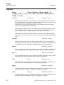
Instruction
ExitCycle - Break current cycle and start next
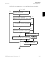
ExitCycle is used to break the current cycle and move the PP back to the first instruction in the main routine.
If the program is executed in continuous mode, it will start to execute the next cycle.
If the execution is in cycle mode, the execution will stop at the first instruction in the
main routine.
Example
VAR num cyclecount:=0;
VAR intnum error_intno;
PROC main()
IF cyclecount = 0 THEN
CONNECT error_intno WITH error_trap;
ISignalDI di_error,1,error_intno;
ENDIF
cyclecount:=cyclecount+1;
! start to do something intelligent
....
ENDPROC
TRAP error_trap
TPWrite “ERROR, I will start on the next item”;
ExitCycle;
ENDTRAP
This will start the next cycle if the signal di_error is set.
Program execution
Execution of ExitCycle in the MAIN program task, results in the following in the
MAIN task:
- On-going robot movements stops
- All robot paths that are not performed at all path levels (both normal and StorePath level) are cleared
- All instructions that are started but not finished at all execution levels (both normal and TRAP level) are interrupted
- The program pointer is moved to the first instruction in the main routine
- The program execution continues to execute the next cycle
RAPID reference part 1, Instructions A-Z
63
ExitCycle
Instruction
Execution of ExitCycle in some other program task (besides MAIN) results in the following in the actual task:
- All instructions that are started but not finished on all execution levels (both
normal and TRAP level) are interrupted
- The program pointer is moved to the first instruction in the main routine
- The program execution continues to execute the next cycle
All other modal things in the program and system are not affected by ExitCycle such as:
- The actual value of variables or persistents
- Any motion settings such as StorePath-RestoPath sequence, world zones, etc.
- Open files, directories, etc.
- Defined interrupts, etc.
When using ExitCycle in routine calls and the entry routine is defined with “Move PP
to Routine ...” or “Call Routine ...”, ExitCycle breaks the current cycle and moves the
PP back to the first instruction in the entry routine (instead of the main routine as specified above).
Syntax
ExitCycle’;’
Related information
Described in:
64
Stopping after a fatal error
Instructions - EXIT
Terminating program execution
Instructions - EXIT
Stopping for program actions
Instructions - Stop
Finishing execution of a routine
Instructions - RETURN
RAPID reference part 1, Instructions A-Z
FOR
Instruction
FOR - Repeats a given number of times
FOR is used when one or several instructions are to be repeated a number of times.
Example
FOR i FROM 1 TO 10 DO
routine1;
ENDFOR
Repeats the routine1 procedure 10 times.
Arguments
FOR Loop counter FROM Start value TO End value
[STEP Step value] DO ... ENDFOR
Loop counter
Identifier
The name of the data that will contain the value of the current loop counter.
The data is declared automatically.
If the loop counter name is the same as any data that already exists in the actual
scope, the existing data will be hidden in the FOR loop and not affected in any
way.
Start value
Data type: Num
The desired start value of the loop counter.
(usually integer values)
End value
Data type: Num
The desired end value of the loop counter.
(usually integer values)
Step value
Data type: Num
The value by which the loop counter is to be incremented (or decremented) each
loop.
(usually integer values)
If this value is not specified, the step value will automatically be set to 1 (or -1 if
the start value is greater than the end value).
RAPID reference part 1, Instructions A-Z
65
FOR
Instruction
Example
FOR i FROM 10 TO 2 STEP -1 DO
a{i} := a{i-1};
ENDFOR
The values in an array are adjusted upwards so that a{10}:=a{9}, a{9}:=a{8} etc.
Program execution
1. The expressions for the start, end, and step values are evaluated.
2. The loop counter is assigned the start value.
3. The value of the loop counter is checked to see whether its value lies between the
start and end value, or whether it is equal to the start or end value. If the value of the
loop counter is outside of this range, the FOR loop stops and program execution continues with the instruction following ENDFOR.
4. The instructions in the FOR loop are executed.
5. The loop counter is incremented (or decremented) in accordance with the step value.
6. The FOR loop is repeated, starting from point 3.
Limitations
The loop counter (of data type num) can only be accessed from within the FOR loop
and consequently hides other data and routines that have the same name. It can only be
read (not updated) by the instructions in the FOR loop.
Decimal values for start, end or step values, in combination with exact termination conditions for the FOR loop, cannot be used (undefined whether or not the last loop is running).
Remarks
If the number of repetitions is to be repeated as long as a given expression is evaluated
to a TRUE value, the WHILE instructions should be used instead.
66
RAPID reference part 1, Instructions A-Z
FOR
Instruction
Syntax
(EBNF)
FOR <loop variable> FROM <expression> TO <expression>
[ STEP <expression> ] DO
<instruction list>
ENDFOR
<loop variable> ::= <identifier>
Related information
Described in:
Expressions
Repeats as long as...
Basic Characteristics - Expressions
Instructions - WHILE
Identifiers
Basic Characteristics Basic Elements
RAPID reference part 1, Instructions A-Z
67
FOR
Instruction
68
RAPID reference part 1, Instructions A-Z
GetSysData
Instruction
GetSysData - Get system data
GetSysData fetches the value and optional symbol name for the current system data of
specified data type.
With this instruction it is possible to fetch data for and the name of the current active
Tool , Work Object or PayLoad (for robot).
Example
PERS tooldata curtoolvalue := [TRUE, [[0, 0, 0], [1, 0, 0, 0]],
[0, [0, 0, 0], [1, 0, 0, 0], 0, 0, 0]];
VAR string curtoolname;
GetSysData curtoolvalue;
Copy current active tool data value to the persistent variable curtoolvalue.
GetSysData curtoolvalue \ObjectName := curtoolname;
Copy also current active tool name to the variable curtoolname.
Arguments
GetSysData
DestObject [\ ObjectName ]
DestObject
Data type: anytype
Persistent for storage of current active system data value.
The data type of this argument also specifies the type of system data (Tool, Work
Object or PayLoad) to fetch.
[\ObjectName]
Data type: string
Option argument (variable or persistent) to also fetch the current active system
data name.
RAPID reference part 1, Instructions A-Z
69
GetSysData
Instruction
Program execution
When running the instruction GetSysData the current data value is stored in the specified persistent in argument DestObject.
If argument \ObjectName is used, the name of the current data is stored in the specified
variable or persistent in argument ObjectName.
Current system data for Tool or Work Object is activated by execution of any move
instruction or can be manually set in the jogging window.
Syntax
GetSysData
[ DestObject’:=’] < persistent(PERS) of anytype>
[’\’ObjectName’:=’ < expression (INOUT) of string> ] ’;’
Related information
Described in:
70
Definition of tools
Data Types - tooldata
Definition of work objects
Data Types - wobjdata
Set system data
Instructions - SetSysData
RAPID reference part 1, Instructions A-Z
GetTrapData
Instruction
Advanced functions
GetTrapData - Get interrupt data for current TRAP
GetTrapData is used in a trap routine to obtain all information about the interrupt that
caused the trap routine to be executed.
To be used in trap routines generated by instruction IError, before use of the instruction ReadErrData.
Example
VAR trapdata err_data;
GetTrapData err_data;
Store interrupt information in the non-value variable err_data.
Arguments
GetTrapData
TrapEvent
TrapEvent
Data type: trapdata
Variable for storage of the information about what caused the trap to be executed.
Limitation
This instruction can only be used in a TRAP routine.
Example
VAR errdomain err_domain;
VAR num err_number;
VAR errtype err_type;
VAR trapdata err_data;
.
TRAP trap_err
GetTrapData err_data;
ReadErrData err_data, err_domain, err_number, err_type;
ENDTRAP
When an error is trapped to the trap routine trap_err, the error domain, the error
number, and the error type are saved into appropriate non-value variables of the
type trapdata.
RAPID reference part 1, Instructions A-Z
71
GetTrapData
Advanced functions
Instruction
Syntax
GetTrapData
[TrapEvent ’:=’] <variable (VAR) of trapdata>’;’
Related information
Described in:
72
Summary of interrupts
RAPID Summary - Interrupts
More information on interrupt management
Basic Characteristics- Interrupts
Interrupt data for current TRAP
Data Types - trapdata
Orders an interrupt on errors
Instructions - IError
Get interrupt data for current TRAP
Instructions- GetTrapData
Gets information about an error
Instructions - ReadErrData
RAPID reference part 1, Instructions A-Z
GOTO
Instruction
GOTO - Goes to a new instruction
GOTO is used to transfer program execution to another line (a label) within the same
routine.
Examples
GOTO next;
.
next:
Program execution continues with the instruction following next.
reg1 := 1;
next:
.
reg1 := reg1 + 1;
IF reg1<=5 GOTO next;
The next program loop is executed five times.
IF reg1>100 GOTO highvalue;
lowvalue:
.
GOTO ready;
highvalue:
.
ready:
If reg1 is greater than 100, the highvalue program loop is executed; otherwise
the lowvalue loop is executed.
Arguments
GOTO
Label
Label
Identifier
The label from where program execution is to continue.
RAPID reference part 1, Instructions A-Z
73
GOTO
Instruction
Limitations
It is only possible to transfer program execution to a label within the same routine.
It is only possible to transfer program execution to a label within an IF or TEST instruction if the GOTO instruction is also located within the same branch of that instruction.
It is only possible to transfer program execution to a label within a FOR or WHILE
instruction if the GOTO instruction is also located within that instruction.
Syntax
(EBNF)
GOTO <identifier>’;’
Related information
Described in:
74
Label
Instructions - label
Other instructions that change the program
flow
RAPID Summary Controlling the Program Flow
RAPID reference part 1, Instructions A-Z
GripLoad
Instruction
GripLoad - Defines the payload of the robot
GripLoad is used to define the payload which the robot holds in its gripper.
Description
It is important to always define the actual tool load and when used, the payload of the
robot too. Incorrect definitions of load data can result in overloading of the robot
mechanical structure.
When incorrect load data is specified, it can often lead to the following consequences:
- If the value in the specified load data is greater than that of the value of the true
load;
-> The robot will not be used to its maximum capacity
-> Impaired path accuracy including a risk of overshooting
If the value in the specified load data is less than the value of the true load;
-> Impaired path accuracy including a risk of overshooting
-> Risk of overloading the mechanical structure
Examples
GripLoad piece1;
The robot gripper holds a load called piece1.
GripLoad load0;
The robot gripper releases all loads.
Arguments
GripLoad
Load
Load
Data type: loaddata
The load data that describes the current payload.
RAPID reference part 1, Instructions A-Z
75
GripLoad
Instruction
Program execution
The specified load affects the performance of the robot.
The default load, 0 kg, is automatically set
- at a cold start-up
- when a new program is loaded
- when starting program executing from the beginning.
Syntax
GripLoad
[ Load ’:=’ ] < persistent (PERS) of loaddata > ’;’
Related information
Described in:
76
Definition of load data
Data Types - loaddata
Definition of tool load
Data Types - tooldata
RAPID reference part 1, Instructions A-Z
IDelete
Instruction
IDelete - Cancels an interrupt
IDelete (Interrupt Delete) is used to cancel (delete) an interrupt.
If the interrupt is to be only temporarily disabled, the instruction ISleep or IDisable
should be used.
Example
IDelete feeder_low;
The interrupt feeder_low is cancelled.
Arguments
IDelete
Interrupt
Interrupt
Data type: intnum
The interrupt identity.
Program execution
The definition of the interrupt is completely erased. To define it again, it must first be
re-connected to the trap routine.
The instruction should be preceded by a stop point. Otherwise the interrupt will be
deactivated before the end point is reached.
Interrupts do not have to be erased; this is done automatically when
- a new program is loaded
- the program is restarted from the beginning
- the program pointer is moved to the start of a routine
Syntax
IDelete
[ Interrupt ‘:=’ ] < variable (VAR) of intnum > ‘;’
RAPID reference part 1, Instructions A-Z
77
IDelete
Instruction
Related information
Described in:
78
Summary of interrupts
RAPID Summary - Interrupts
Temporarily disabling an interrupt
Instructions - ISleep
Temporarily disabling all interrupts
Instructions - IDisable
RAPID reference part 1, Instructions A-Z
IDisable
Instruction
IDisable - Disables interrupts
IDisable (Interrupt Disable) is used to disable all interrupts temporarily. It may, for
example, be used in a particularly sensitive part of the program where no interrupts
may be permitted to take place in case they disturb normal program execution.
Example
IDisable;
FOR i FROM 1 TO 100 DO
character[i]:=ReadBin(sensor);
ENDFOR
IEnable;
No interrupts are permitted as long as the serial channel is reading.
Program execution
Interrupts, that occur during the time in which an IDisable instruction is in effect, are
placed in a queue. When interrupts are permitted once more, the interrupt(s) of the program then immediately starts generating, executed in “first in - first out” order in the
queue.
IEnable is active by default. IEnable is automatically set
- at a cold start-up
- when starting program execution from the beginning of main
- after executing one cycle (passing main) or executing ExitCycle
Syntax
IDisable‘;’
Related information
Described in:
Summary of interrupts
RAPID Summary - Interrupt
Permitting interrupts
Instructions - IEnable
RAPID reference part 1, Instructions A-Z
79
IDisable
Instruction
80
RAPID reference part 1, Instructions A-Z
IEnable
Instruction
IEnable - Enables interrupts
IEnable (Interrupt Enable) is used to enable interrupts during program execution.
Example
IDisable;
FOR i FROM 1 TO 100 DO
character[i]:=ReadBin(sensor);
ENDFOR
IEnable;
No interrupts are permitted as long as the serial channel is reading. When it has
finished reading, interrupts are once more permitted.
Program execution
Interrupts which occur during the time in which an IDisable instruction is in effect, are
placed in a queue. When interrupts are permitted once more (IEnable), the interrupt(s)
of the program then immediately start generating, executed in “first in - first out” order
in the queue.Program execution then continues in the ordinary program and interrupts
which occur after this are dealt with as soon as they occur.
Interrupts are always permitted when a program is started from the beginning,. Interrupts disabled by the ISleep instruction are not affected by the IEnable instruction.
Syntax
IEnable‘;’
Related information
Described in:
Summary of interrupts
RAPID Summary - Interrupts
Permitting no interrupts
Instructions - IDisable
RAPID reference part 1, Instructions A-Z
81
IEnable
Instruction
82
RAPID reference part 1, Instructions A-Z
IError
Instruction
Advanced functions
IError - Orders an interrupt on errors
IError (Interrupt Errors) is used to order and enable an interrupt when an error occurs.
Error, warning, or state change can be logged with IError.
Refer to the User Guide - Error Management, System and Error Messages
for more information.
Example
VAR intnum err_int;
...
CONNECT err_int WITH err_trap;
IError COMMON_ERR, TYPE_ALL, err_int;
Orders an interrupt in RAPID and execution of the TRAP routine err_trap each
time an error, warning, or state change is generated in the system.
Arguments
IError
ErrorDomain [\ErrorId] ErrorType Interrupt
ErrorDomain
Data type: errdomain
The error domain that is to be monitored.
Refer to predefined data of type errdomain.
To specify any domain, use COMMON_ERR.
[\ErrorId]
Data type: num
Optionally, the number of a specific error that is to be monitored.
The error number must be specified without the first digit (error domain) of the
complete error number.
E.g. 10008 Program restarted, must be specified as 0008 or only 8.
ErrorType
Data type: errtype
The type of event, such as error, warning, or state change, that is to be monitored.
Refer to predefined data of type errtype.
To specify any type, use TYPE_ALL.
Interrupt
Data type: intnum
The interrupt identity. This should have been previously connected to a trap routine by means of the instruction CONNECT.
RAPID reference part 1, Instructions A-Z
83
IError
Advanced functions
Instruction
Program execution
The corresponding trap routine is automatically called when an error occurs, in the
specified domain, of the specified type and optionally with the specified error number.
When this has been executed, program execution continues from where the interrupt
occurred
Example
VAR intnum err_interrupt;
VAR trapdata err_data;
VAR errdomain err_domain;
VAR num err_number;
VAR errtype err_type;
...
CONNECT err_interrupt WITH trap_err;
IError COMMON_ERR, TYPE_ERR, err_interupt;
...
IDelete err_interrupt;
...
TRAP trap_err
GetTrapData err_data;
ReadErrData err_data, err_domain, err_number, err_type;
! Set domain no 1 ... 13
SetGO go_err1, err_domain;
! Set error no 1 ...9999
SetGO go_err2, err_number;
ENDTRAP
When an error occurs (only error, not warning, or state change), the error number
is retrieved in the trap routine and its value is used to set 2 groups of digital outputs.
Limitation
It is not possible to order an interrupt on internal errors.
The same variable for interrupt identity cannot be used more than once, without first
deleting it. Interrupts should therefore be handled as shown in one of the alternatives
below.
VAR intnum err_interrupt;
84
RAPID reference part 1, Instructions A-Z
IError
Instruction
Advanced functions
PROC main ( )
CONNECT err_interrupt WITH err_trap;
IError COMMON_ERR, TYPE_ERR, err_interupt;
WHILE TRUE DO
:
:
ENDWHILE
ENDPROC
Interrupts are activated at the beginning of the program. These instructions are
then kept outside the main flow of the program.
PROC main ( )
VAR intnum err_interrupt;
CONNECT err_interrupt WITH err_trap;
IError COMMON_ERR, TYPE_ERR, err_interupt;
:
:
IDelete err_interrupt;
ENDPROC
The interrupt is deleted at the end of the program and is then reactivated. It
should be noted, in this case, that the interrupt is inactive for a short period.
Syntax
IError
[ErrorDomain ’:=’] <expression (IN) of errdomain>
[’\’ErrorId’:=’ <expression (IN) of num>’]’ ’,’
[ErrorType ’:=’] <expression (IN) of errtype> ‘,’
[Interrupt ’:=’] <variable (VAR) of intnum>’;’
Related information
Described in:
Summary of interrupts
RAPID Summary - Interrupts
More information on interrupt management
Basic Characteristics- Interrupts
Error domains, predefined constants
Data Types - errdomain
Error types, predefined constants
Data Types - errtype
Get interrupt data for current TRAP
Instructions - GetTrapData
Gets information about an error
Instructions - ReadErrData
RAPID reference part 1, Instructions A-Z
85
IError
Advanced functions
86
Instruction
RAPID reference part 1, Instructions A-Z
IF
Instruction
IF - If a condition is met, then ...; otherwise ...
IF is used when different instructions are to be executed depending on whether a condition is met or not.
Examples
IF reg1 > 5 THEN
Set do1;
Set do2;
ENDIF
The do1 and do2 signals are set only if reg1 is greater than 5.
IF reg1 > 5 THEN
Set do1;
Set do2;
ELSE
Reset do1;
Reset do2;
ENDIF
The do1 and do2 signals are set or reset depending on whether reg1 is greater
than 5 or not.
Arguments
IF Condition THEN ...
{ELSEIF Condition THEN ...}
[ELSE ...]
ENDIF
Condition
Data type: bool
The condition that must be satisfied for the instructions between THEN and
ELSE/ELSEIF to be executed.
RAPID reference part 1, Instructions A-Z
87
IF
Instruction
Example
IF counter > 100 THEN
counter := 100;
ELSEIF counter < 0 THEN
counter := 0;
ELSE
counter := counter + 1;
ENDIF
Counter is incremented by 1. However, if the value of counter is outside the limit
0-100, counter is assigned the corresponding limit value.
Program execution
The conditions are tested in sequential order, until one of them is satisfied. Program
execution continues with the instructions associated with that condition. If none of the
conditions are satisfied, program execution continues with the instructions following
ELSE. If more than one condition is met, only the instructions associated with the first
of those conditions are executed.
Syntax
(EBNF)
IF <conditional expression> THEN
<instruction list>
{ELSEIF <conditional expression> THEN <instruction list> | <EIF>}
[ELSE
<instruction list>]
ENDIF
Related information
Described in:
Conditions (logical expressions)
88
Basic Characteristics - Expressions
RAPID reference part 1, Instructions A-Z
Incr
Instruction
Incr - Increments by 1
Incr is used to add 1 to a numeric variable or persistent.
Example
Incr reg1;
1 is added to reg1, i.e. reg1:=reg1+1.
Arguments
Incr Name
Name
Data type: num
The name of the variable or persistent to be changed.
Example
WHILE stop_production=0 DO
produce_part;
Incr no_of_parts;
TPWrite "No of produced parts= "\Num:=no_of_parts;
ENDWHILE
The number of parts produced is updated on the teach pendant each cycle.
Production continues to run as long as the signal stop_production is not set.
Syntax
Incr
[ Name ’:=’ ] < var or pers (INOUT) of num > ’;’
Related information
Described in:
Decrementing a variable by 1
Instructions - Decr
Adding any value to a variable
Instructions - Add
Changing data using an arbitrary
expression, e.g. multiplication
Instructions - :=
RAPID reference part 1, Instructions A-Z
89
Incr
Instruction
90
RAPID reference part 1, Instructions A-Z
InvertDO
Instruction
InvertDO - Inverts the value of a digital output signal
InvertDO (Invert Digital Output) inverts the value of a digital output signal (0 -> 1 and
1 -> 0).
Example
InvertDO do15;
The current value of the signal do15 is inverted.
Arguments
InvertDO
Signal
Signal
Data type: signaldo
The name of the signal to be inverted.
Program execution
The current value of the signal is inverted (see Figure 3).
:
1
Signal level
0
Execution of the instruction InvertDO
Execution of the instruction InvertDO
1
Signal level
0
Figure 3 Inversion of a digital output signal.
Syntax
InvertDO
[ Signal ’:=’ ] < variable (VAR) of signaldo > ’;’
RAPID reference part 1, Instructions A-Z
91
InvertDO
Instruction
Related information
Described in:
92
Input/Output instructions
RAPID Summary - Input and Output
Signals
Input/Output functionality in general
Motion and I/O Principles - I/O Principles
Configuration of I/O
System Parameters
RAPID reference part 1, Instructions A-Z
IODisable
Instruction
IODisable - Disable I/O unit
IODisable is used to disable an I/O unit during program execution.
I/O units are automatically enabled after start-up if they are defined in the system
parameters. When required for some reason, I/O units can be disabled or enabled during program execution.
Examples
CONST string cell1:=”cell1”;
IODisable cell1, 5;
Disable I/O unit with name cell1.Wait max. 5 s.
Arguments
IODisable
UnitName MaxTime
UnitName
Data type: string
The name of the I/O unit to be disabled (with same name as configured).
MaxTime
Data type: num
The maximum period of waiting time permitted, expressed in seconds. If this
time runs out before the I/O unit has finished the disable steps, the error handler
will be called, if there is one, with the error code ERR_IODISABLE. If there is
no error handler, the execution will be stopped.
To disable an I/O unit takes about 0-5 s.
Program execution
The specified I/O unit starts the disable steps. The instruction is ready when the disable
steps are finished. If the MaxTime runs out before the I/O unit has finished the disable
steps, a recoverable error will be generated.
After disabling an I/O unit, any setting of outputs in this unit will result in an error.
RAPID reference part 1, Instructions A-Z
93
IODisable
Instruction
Error handling
Following recoverable errors can be generated. The errors can be handled in an error
handler. The system variable ERRNO will be set to:
ERR_IODISABLE
ERR_CALLIO_INTER
ERR_NAME_INVALID
if the time out time runs out before the unit is
disabled.
if an IOEnable or IODisable request is interrupted
by another request to the same unit.
if the unit name don’t exist or if the unit isn’t
allowed to be disabled.
Example
PROC go_home()
VAR num recover_flag :=0;
...
! Start to disable I/O unit cell1
recover_flag := 1;
IODisable “cell1”, 0;
! Move to home position
MoveJ home, v1000,fine,tool1;
! Wait until disable of I/O unit cell1 is ready
recover_flag := 2;
IODisable “cell1”, 5;
...
ERROR
IF ERRNO = ERR_IODISABLE THEN
IF recover_flag = 1 THEN
TRYNEXT;
ELSEIF recover_flag = 2 THEN
RETRY;
ENDIF
ELSEIF ERRNO = ERR_EXCRTYMAX THEN
ErrWrite “IODisable error”, “Not possible to disable I/O unit cell1”;
Stop;
ENDIF
ENDPROC
To save cycle time, the I/O unit cell1 is disabled during robot movement to the
home position. With the robot at the home position, a test is done to establish
whether or not the I/O unit cell1 is fully disabled. After the max. number of retries
(5 with a waiting time of 5 s), the robot execution will stop with an error message.
The same principle can be used with IOEnable (this will save more cycle time
compared with IODisable).
94
RAPID reference part 1, Instructions A-Z
IODisable
Instruction
Syntax
IODisable
[ UnitName ’:=’ ] < expression (IN) of string> ’,’
[ MaxTime ’:=’ ] < expression (IN) of num > ’;’
Related information
Described in:
Enabling an I/O unit
Instructions - IOEnable
Input/Output instructions
RAPID Summary Input and Output Signals
Input/Output functionality in general
I/O Principles
Motion and I/O Principles -
Configuration of I/O
User’s Guide - System Parameters
RAPID reference part 1, Instructions A-Z
95
IODisable
Instruction
96
RAPID reference part 1, Instructions A-Z
IODNGetAttr
Instruction
IODNGetAttr - Get attribute from I/O-unit
IODNGetAttr (I/O DeviceNet Get Attribute) is used to get an attribute from an I/O unit
on the DeviceNet.
Examples
VAR string name;
...
IODNGetAttr "dsqc328", "6,20 01 24 01 30 07,17,20", name \Timeout:=3;
This will get the product name from the I/O unit dsqc328. The product name will
be stored in the string variable name. Timeout after 3 seconds.
VAR string serialno;
...
IODNGetAttr "dsqc328", "6,20 01 24 01 30 06,9,4", serialno;
This will get the serial number from the I/O unit dsqc328. The value will be
stored in the string variable serialno. Timeout after default 5 seconds.
Arguments
IODNGetAttr
UnitName Path GetValue [ \Timeout ]
UnitName
Data type: string
The name of the I/O unit (same name as configured).
Path
Data type: string
The values for the path are found in the EDS file. For a more detailed description
see the Open DeviceNet Vendor Association “DeviceNet Specification rev. 2.0”.
GetValue
Data type: string
The value of the attribute will be stored in this string variable. The string length
is limited to 30 characters.
[ \Timeout]
Data type: num
The period of waiting time permitted, expressed in seconds.
Default timeout 5 second, if this argument is omitted.
RAPID reference part 1, Instructions A-Z
97
IODNGetAttr
Instruction
Program execution
The program is waiting until the I/O unit has answered.
If the Timeout runs out before the I/O unit has answered, the error handler will be
called, if there is one, with the error code ERR_IODN_TIMEOUT.
If there is no error handler, the execution will be stopped.
Error handling
Following recoverable errors can be generated. The errors can be handled in an error
handler. The system variable ERRNO will be set to:
ERR_IODN_TIMEOUT
ERR_NAME_INVALID
ERR_MSG_PENDING
If the timeout time runs out before the unit has
answered back to confirm ready.
If the unit name doesn’t exist
A message is already sent to the unit. Wait a
short while (e.g. 100ms) and try again.
Syntax
IODNGetAttr
[ UnitName ’:=’ ] < expression (IN) of string > ’,’
[ Path ’:=’ ] < expression (IN) of string > ’,’
[ GetValue ’:=’ ] < variable (VAR) of string >
[ ’\’ Timeout ’:=’ < expression (IN) of num > ] ’;’
Related information
Described in:
98
Open DeviceNet Vendor Association
DeviceNet Specification rev. 2.0
Configuration of I/O
User’s Guide - System Parameters
Configuration of I/O
IO Plus User’s Guide
Configuration of I/O
RAPID Developer’s Manual - System
Parameters
Input/Output functionality in general
Motion and I/O Principles - I/O Principles
Input/Output instructions
RAPID Summary - Input and Output
Signals
Set I/O unit attribute
Instructions - IODNSetAttr
RAPID reference part 1, Instructions A-Z
IODNSetAttr
Instruction
IODNSetAttr - Set attribute for an I/O-unit
IODNSetAttr (I/O DeviceNet Set Attribute) is used to set an attribute for an I/O unit on
the DeviceNet.
Examples
IODNSetAttr "dsqc328", "6,20 1D 24 01 30 65,8,1", ”5” \Timeout:=3;
This will set the filter time to 5 for the falling edge on insignal 1 on the unit
dsqc328. Timeout after 3 seconds.
IODNSetAttr "dsqc328", "6,20 1D 24 01 30 64,8,1", ”4”;
This will set the filter time to 4 for the rising edge on insignal 1 on the unit
dsqc328. Timeout after default 5 seconds.
Arguments
IODNSetAttr
UnitName Path SetValue [ \Timeout ]
UnitName
Data type: string
The name of the I/O unit (same name as configured).
Path
Data type: string
The values for the path is found in the EDS file. For a more detailed description
see the Open DeviceNet Vendor Association “DeviceNet Specification rev. 2.0”.
SetValue
Data type: string
The value to set the attribute to. The string length is limited to 30 characters.
[ \Timeout]
Data type: num
The period of waiting time permitted, expressed in seconds.
Default timeout 5 second, if this argument is omitted.
Program execution
The program is waiting until the I/O unit has answered.
If the Timeout runs out before the I/O unit has answered, the error handler will be
called, if there is one, with the error code ERR_IODN_TIMEOUT. If there is no error
handler, the execution will be stopped.
RAPID reference part 1, Instructions A-Z
99
IODNSetAttr
Instruction
Error handling
Following recoverable errors can be generated. The errors can be handled in an error
handler. The system variable ERRNO will be set to:
ERR_IODN_TIMEOUT
If the timeout time runs out before the unit has
answered back to confirm ready.
ERR_NAME_INVALID
If the unit name doesn’t exist.
ERR_MSG_PENDING
A message is already sent to the unit. Wait a short
while (e.g. 100ms) and try again.
Syntax
IODNSetAttr
[ UnitName ’:=’ ] < expression (IN) of string > ’,’
[ Path ’:=’ ] < expression (IN) of string > ’,’
[ SetValue’:=’ ] < expression (IN) of string >
[ ’\’ Timeout’:=’ < expression (IN) of num > ] ’;’
Related information
Described in:
100
Open DeviceNet Vendor Association
DeviceNet Specification rev. 2.0
Configuration of I/O
User’s Guide - System Parameters
Configuration of I/O
IO Plus User’s Guide
Configuration of I/O
RAPID Developer’s Manual - System
Parameters
Input/Output functionality in general
Motion and I/O Principles - I/O Principles
Input/Output instructions
RAPID Summary - Input and Output
Signals
Get I/O unit attribute
Instructions - IODNGetAttr
RAPID reference part 1, Instructions A-Z
IOEnable
Instruction
IOEnable - Enable I/O unit
IOEnable is used to enable an I/O unit during program execution.
I/O units are automatically enabled after start-up if they are defined in the system
parameters. When required for some reason, I/O units can be disabled or enabled during program execution.
Examples
CONST string cell1:=”cell1”;
IOEnable cell1, 5;
Enable I/O unit with name cell1. Wait max. 5 s.
Arguments
IOEnable
UnitName MaxTime
UnitName
Data type: string
The name of the I/O unit to be enabled (with same name as configured).
MaxTime
Data type: num
The maximum period of waiting time permitted, expressed in seconds. If this
time runs out before the I/O unit has finished the enable steps, the error handler
will be called, if there is one, with the error code ERR_IOENABLE. If there is
no error handler, the execution will be stopped.
To enable an I/O unit takes about 2-5 s.
Program execution
The specified I/O unit starts the enable steps. The instruction is ready when the enable
steps are finished. If the MaxTime runs out before the I/O unit has finished the enable
steps, a recoverable error will be generated.
After a sequence of IODisable - IOEnable, all outputs for the current I/O unit will be
set to the old values (before IODisable).
RAPID reference part 1, Instructions A-Z
101
IOEnable
Instruction
Error handling
Following recoverable errors can be generated. The errors can be handled in an error
handler. The system variable ERRNO will be set to:
ERR_IOENABLE
ERR_CALLIO_INTER
ERR_NAME_INVALID
if the time out time runs out before the unit is
enabled.
if an IOEnable or IODisable request is interrupted
by another request to the same unit.
if the unit name don’t exist or if the unit isn’t
allowed to be disabled.
Example
IOEnable can also be used to check whether some I/O unit is disconnected for some
reason.
VAR num max_retry:=0;
...
IOEnable “cell1”, 0;
SetDO cell1_sig3, 1;
...
ERROR
IF ERRNO = ERR_IOENABLE THEN
IF max_retry < 5 THEN
WaitTime 1;
max_retry := max_retry + 1;
RETRY;
ELSE
RAISE;
ENDIF
ENDIF
Before using signals on the I/O unit cell1, a test is done by trying to enable the I/
O unit with timeout after 0 sec. If the test fails, a jump is made to the error handler. In the error handler, the program execution waits for 1 sec. and a new retry
is made. After 5 retry attempts the error ERR_IOENABLE is propagated to the
caller of this routine.
Syntax
IOEnable
[ UnitName ’:=’ ] < expression (IN) of string> ’,’
[ MaxTime ’:=’ ] < expression (IN) of num > ’;’
102
RAPID reference part 1, Instructions A-Z
IOEnable
Instruction
Related information
Described in:
More examples
Instructions - IODisable
Disabling an I/O unit
Instructions - IODisable
Input/Output instructions
RAPID Summary Input and Output Signals
Input/Output functionality in general
Motion and I/O Principles I/O Principles
Configuration of I/O
User’s Guide - System Parameters
RAPID reference part 1, Instructions A-Z
103
IOEnable
Instruction
104
RAPID reference part 1, Instructions A-Z
ISignalAI
Instruction
Advanced functions
ISignalAI - Interrupts from analog input signal
ISignalAI (Interrupt Signal Analog Input) is used to order and enable interrupts from
an analog input signal.
Example
VAR intnum sig1int;
CONNECT sig1int WITH iroutine1;
ISignalAI \Single, ai1, AIO_BETWEEN, 1.5, 0.5, 0, sig1int;
Orders an interrupt which is to occur the first time the logical value of the analog
input signal ai1 is between 0.5 and 1.5. A call is then made to the iroutine1 trap
routine.
ISignalAI ai1, AIO_BETWEEN, 1.5, 0.5, 0.1, sig1int;
Orders an interrupt which is to occur each time the logical value of the analog
input signal ai1 is between 0.5 and 1.5, and the absolute signal difference compared to the stored reference value is bigger than 0.1.
ISignalAI ai1, AIO_OUTSIDE, 1.5, 0.5, 0.1, sig1int;
Orders an interrupt which is to occur each time the logical value of the analog
input signal ai1 is lower than 0.5 or higher than 1.5, and the absolute signal difference compared to the stored reference value is bigger than 0.1.
Arguments
ISignalAI [\Single] Signal Condition HighValue LowValue
DeltaValue [\DPos] | [\DNeg] Interrupt
[\Single]
Data type: switch
Specifies whether the interrupt is to occur once or cyclically.
If the argument Single is set, the interrupt occurs once at the most. If the argument is omitted, an interrupt will occur each time its condition is satisfied.
Signal
Data type: signalai
The name of the signal that is to generate interrupts.
RAPID reference part 1, Instructions A-Z
105
ISignalAI
Advanced functions
Instruction
Condition
Data type: aiotrigg
Specifies how HighValue and LowValue define the condition to be satisfied:
- AIO_ABOVE_HIGH:logical value of the signal is above HighValue
- AIO_BELOW_HIGH:logical value of the signal is below HighValue
- AIO_ABOVE_LOW:logical value of the signal is above LowValue
- AIO_BELOW_LOW:logical value of the signal is below LowValue
- AIO_BETWEEN:logical value of the signal is between LowValue
and HighValue
- AIO_OUTSIDE:logical value of the signal is above HighValue or
below LowValue
- AIO_ALWAYS:independently of HighValue and LowValue
HighValue
Data type: num
High logical value to define the condition.
LowValue
Data type: num
Low logical value to define the condition.
DeltaValue
Data type: num
Defines the minimum logical signal difference before generation of a new interrupt. The current signal value compared to the stored reference value must be
greater than the specified DeltaValue before generation of a new interrupt.
[\DPos]
Data type: switch
Specifies that only positive logical signal differences will give new interrupts.
[\DNeg]
Data type: switch
Specifies that only negative logical signal differences will give new interrupts.
If none of \DPos and \DNeg argument is used, both positive and negative differences will generate new interrupts.
Interrupt
Data type: intnum
The interrupt identity. This interrupt should have previously been connected to a
trap routine by means of the instruction CONNECT.
106
RAPID reference part 1, Instructions A-Z
ISignalAI
Instruction
Advanced functions
Program execution
When the signal fulfils the specified conditions (both Condition and DeltaValue), a
call is made to the corresponding trap routine. When this has been executed, program
execution continues from where the interrupt occurred.
Conditions for interrupt generation
Before the interrupt subscription is ordered, each time the signal is sampled, the value
of the signal is read, saved, and later used as a reference value for the DeltaValue condition.
At the interrupt subscription time, if specified DeltaValue = 0 and after the interrupt
subscription time always at each time the signal is sampled, its value is then compared
to HighValue and LowValue according to Condition and with consideration to
DeltaValue, to generate or not generate an interrupt. If the new read value satisfies the
specified HighValue and LowValue Condition, but its difference compared to the last
stored reference value is less or equal to the DeltaValue argument, no interrupt occurs.
If the signal difference is not in the specified direction, no interrupts will occur.
(argument \DPos or \DNeg).
The stored reference value for the DeltaValue condition is updated with a newly read
value for later use at any sample, if the following conditions are satisfied:
- Argument Condition with specified HighValue and LowValue
(within limits)
- Argument DeltaValue
(sufficient signal change in any direction, independently of specified switch
\DPos or \DNeg)
The reference value is only updated at the sample time, not at the interrupt subscription
time.
An interrupt is also generated at the sample for update of the reference value, if the
direction of the signal difference is in accordance with the specified argument
(any direction, \DPos or \DNeg).
When the \Single switch is used, only one interrupt at the most will be generated.
If the switch \Single (cyclic interrupt) is not used, a new test of the specified conditions
(both Condition and DeltaValue) is made at every sample of the signal value, compared to the current signal value and the last stored reference value, to generate or not
generate an interrupt.
RAPID reference part 1, Instructions A-Z
107
ISignalAI
Advanced functions
Instruction
Condition for interrupt generation at interrupt subscription time
Sample before interrupt subscription
RefValue := CurrentValue
Interrupt
False
subscription
CurrentValue tested against Condition
HighValue and LowValue
True
False
DeltaValue = 0
True
Interrupt generated
Continue
108
RAPID reference part 1, Instructions A-Z
ISignalAI
Instruction
Advanced functions
Condition for interrupt generation at each sample after interrupt subscription
New Sample
False
CurrentValue checked against Condition
HighValue and LowValue
True
True
No DPos or DNeg specified and
ABS(CurrentValue - RefValue) > DeltaValue
False
DPos specified and
(CurrentValue - RefValue) > DeltaValue
True
False
DNeg specified and
(RefValue - CurrentValue) > DeltaValue
True
False
RefValue := CurrentValue
ABS(CurrentValue - RefValue) > DeltaValue
False
Interrupt
generated
True
RefValue := CurrentValue
Continue
RAPID reference part 1, Instructions A-Z
109
ISignalAI
Advanced functions
Instruction
Example 1 of interrupt generation
Signal logical value
HighValue
Signal Value
LowValue
0
1
2
3
4
5
6
7
8
Time for order of interrupt subscription
Storage of reference value
9
10
11
12
Samples
Assuming the interrupt is ordered between sample 0 and 1, the following instruction
will give the following results:
ISignalAI ai1, AIO_BETWEEN, 6.1, 2,2, 1.0, sig1int;
sample 1 will generate an interrupt, because the signal value is between HighValue and LowValue and the signal difference compared to sample 0 is more than
DeltaValue.
sample 2 will generate an interrupt, because the signal value is between HighValue and LowValue and the signal difference compared to sample 1 is more than
DeltaValue.
samples 3, 4, 5 will not generate any interrupt, because the signal difference is
less than DeltaValue.
sample 6 will generate an interrupt.
samples 7 to 10 will not generate any interrupt, because the signal is above
HighValue
sample 11 will not generate any interrupt, because the signal difference compared
to sample 6 is equal to DeltaValue.
sample 12 will not generate any interrupt, because the signal difference compared
to sample 6 is less than DeltaValue.
110
RAPID reference part 1, Instructions A-Z
ISignalAI
Instruction
Advanced functions
Example 2 of interrupt generation
Signal logical value
HighValue
Signal Value
LowValue
0
1
2
3
4
5
6
7
8
Time for order of interrupt subscription
Storage of reference value
9
10
11
12
Samples
Assuming the interrupt is ordered between sample 0 and 1, the following instruction
will give the following results:
ISignalAI ai1, AIO_BETWEEN, 6.1, 2,2, 1.0 \DPos, sig1int;
A new reference value is stored at sample 1 and 2, because the signal is within
limits and the absolute signal difference between the current value and the last
stored reference value is greater than 1.0.
No interrupt will be generated because the signal changes are in the negative
direction.
sample 6 will generate an interrupt, because the signal value is between HighValue and LowValue and the signal difference in the positive direction compared
to sample 2 is more than DeltaValue.
RAPID reference part 1, Instructions A-Z
111
ISignalAI
Advanced functions
Instruction
Example 3 of interrupt generation
Signal logical value
HighValue
Signal Value
LowValue
0
1
2
3
4
5
6
7
8
Time for order of interrupt subscription
Storage of reference value
9
10
11
12
Samples
Assuming the interrupt is ordered between sample 0 and 1, the following instruction
will give the following results:
ISignalAI \Single, ai1, AIO_OUTSIDE, 6.1, 2,2, 1.0 \DPos, sig1int;
A new reference value is stored at sample 7, because the signal is within limits
and the absolute signal difference between the current value and the last stored
reference value is greater than 1.0
sample 8 will generate an interrupt, because the signal value is above HighValue
and the signal difference in the positive direction compared to sample 7 is more
than DeltaValue.
112
RAPID reference part 1, Instructions A-Z
ISignalAI
Instruction
Advanced functions
Example 4 of interrupt generation
Signal logical value
HighValue
Signal Value
LowValue
0
1
2
3
4
5
6
7
8
Time for order of interrupt subscription
Storage of reference value
9
10
11
12
Samples
Assuming the interrupt is ordered between sample 0 and 1, the following instruction
will give the following results:
ISignalAI ai1, AIO_ALWAYS, 6.1, 2,2, 1.0 \DPos, sig1int;
A new reference value is stored at sample 1 and 2, because the signal is within
limits and the absolute signal difference between the current value and the last
stored reference value is greater than 1.0
sample 6 will generate an interrupt, because the signal difference in the positive
direction compared to sample 2 is more than DeltaValue.
sample 7 and 8 will generate an interrupt, because the signal difference in the
positive direction compared to previous sample is more than DeltaValue.
A new reference value is stored at sample 11 and 12, because the signal is within
limits and the absolute signal difference between the current value and the last
stored reference value is greater than 1.0
RAPID reference part 1, Instructions A-Z
113
ISignalAI
Advanced functions
Instruction
Error handling
If there is a subscription of interrupt on an analog input signal, an interrupt will be given
for every change in the analog value that satisfies the condition specified when ordering
the interrupt subscription. If the analog value is noisy, many interrupts can be generated, even if only one or two bits in the analog value are changed.
To avoid generating interrupts for small changes of the analog input value, set the
DeltaValue to a level greater than 0. Then no interrupts will be generated until a change
of the analog value is greater than the specified DeltaValue.
Limitations
The HighValue and LowValue arguments should be in the range: logical maximum
value, logical minimum value defined for the signal.
HighValue must be above LowValue.
DeltaValue must be 0 or positive.
The limitations for the interrupt identity are the same as for ISignalDI.
Syntax
ISignalAI
[ ’\’Single’,’]
[ Signal’:=’ ]<variable (VAR) of signalai>’,’
[ Condition’:=’ ]<expression (IN) of aiotrigg>’,’
[ HighValue’:=’ ]<expression (IN) of num>’,’
[ LowValue’:=’ ]<expression (IN) of num>’,’
[ DeltaValue’:=’ ]<expression (IN) of num>
[ ’\’DPos] | [ ’\’DNeg] ’,’
[ Interrupt’:=’ ]<variable (VAR) of intnum>’;’
114
RAPID reference part 1, Instructions A-Z
ISignalAI
Instruction
Advanced functions
Related information
Described in:
Summary of interrupts
RAPID Summary - Interrupts
Definition of constants
Data Types - aiotrigg
Interrupt from analog output signal
Instructions - ISignalAO
Interrupt from digital input signal
Instructions - ISignalDI
Interrupt from digital output signal
Instructions - ISignalDO
More information on interrupt management
Basic Characteristics - Interrupts
More examples
Data Types - intnum
Related system parameters (filter)
System Parameters - IO Signals
RAPID reference part 1, Instructions A-Z
115
ISignalAI
Advanced functions
116
Instruction
RAPID reference part 1, Instructions A-Z
ISignalAO
Instruction
Advanced functions
ISignalAO - Interrupts from analog output signal
ISignalAO (Interrupt Signal Analog Output) is used to order and enable interrupts from
an analog output signal.
Example
VAR intnum sig1int;
CONNECT sig1int WITH iroutine1;
ISignalAO \Single, ao1, AIO_BETWEEN, 1.5, 0.5, 0, sig1int;
Orders an interrupt which is to occur the first time the logical value of the analog
output signal ao1 is between 0.5 and 1.5. A call is then made to the iroutine1 trap
routine.
ISignalAO ao1, AIO_BETWEEN, 1.5, 0.5, 0.1, sig1int;
Orders an interrupt which is to occur each time the logical value of the analog
output signal ao1 is between 0.5 and 1.5, and the absolute signal difference compared to the previous stored reference value is bigger than 0.1.
ISignalAO ao1, AIO_OUTSIDE, 1.5, 0.5, 0.1, sig1int;
Orders an interrupt which is to occur each time the logical value of the analog
output signal ao1 is lower than 0.5 or higher than 1.5, and the absolute signal difference compared to the previous stored reference value is bigger than 0.1.
Arguments
ISignalAO [\Single] Signal Condition HighValue LowValue
DeltaValue [\DPos] | [\DNeg] Interrupt
[\Single]
Data type: switch
Specifies whether the interrupt is to occur once or cyclically.
If the argument Single is set, the interrupt occurs once at the most. If the argument is omitted, an interrupt will occur each time its condition is satisfied.
Signal
Data type: signalao
The name of the signal that is to generate interrupts.
Condition
Data type: aiotrigg
Specifies how HighValue and LowValue define the condition to be satisfied:
RAPID reference part 1, Instructions A-Z
117
ISignalAO
Advanced functions
Instruction
AIO_ABOVE_HIGH: logical value of the signal is above HighValue
AIO_BELOW_HIGH: logical value of the signal is below HighValue
AIO_ABOVE_LOW: logical value of the signal is above LowValue
AIO_BELOW_LOW: logical value of the signal is below LowValue
AIO_BETWEEN:
logical value of the signal is between LowValue and
HighValue
AIO_OUTSIDE:
logical value of the signal is above HighValue or
below LowValue
AIO_ALWAYS:
independently of HighValue and LowValue
HighValue
Data type: num
High logical value to define the condition.
LowValue
Data type: num
Low logical value to define the condition.
DeltaValue
Data type: num
Defines the minimum logical signal difference before generation of a new interrupt. The current signal value compared to the previous stored reference value
must be greater than the specified DeltaValue before generation of a new interrupt.
[\DPos]
Data type: switch
Specifies that only positive logical signal differences will give new interrupts.
[\DNeg]
Data type: switch
Specifies that only negative logical signal differences will give new interrupts.
If neither of the \DPos and \DNeg arguments are used, both positive and negative
differences will generate new interrupts.
Interrupt
Data type: intnum
The interrupt identity. This interrupt should have previously been connected to a
trap routine by means of the instruction CONNECT.
118
RAPID reference part 1, Instructions A-Z
ISignalAO
Instruction
Advanced functions
Program execution
See instruction ISignalAI for information about:
- Program execution
- Condition for interrupt generation
- More examples
Same principles are valid for ISignalAO as for ISignalAI.
Limitations
The HighValue and LowValue arguments should be in the range: logical maximum
value, logical minimum value, defined for the signal.
HighValue must be above LowValue.
DeltaValue must be 0 or positive.
The limitations for the interrupt identity are the same as for ISignalDO.
Syntax
ISignalAO
[ ’\’Single’,’]
[ Signal’:=’ ]<variable (VAR) of signalao>’,’
[ Condition’:=’ ]<expression (IN) of aiotrigg>’,’
[ HighValue’:=’ ]<expression (IN) of num>’,’
[ LowValue’:=’ ]<expression (IN) of num>’,’
[ DeltaValue’:=’ ]<expression (IN) of num>
[ ’\’DPos] | [ ’\’DNeg] ’,’
[ Interrupt’:=’ ]<variable (VAR) of intnum>’;’
RAPID reference part 1, Instructions A-Z
119
ISignalAO
Advanced functions
Instruction
Related information
Described in:
120
Summary of interrupts
RAPID Summary - Interrupts
Definition of constants
Data Types - aiotrigg
Interrupt from analog input signal
Instructions - ISignalAI
Interrupt from digital input signal
Instructions - ISignalDI
Interrupt from digital output signal
Instructions - ISignalDO
More information on interrupt management
Basic Characteristics - Interrupts
More examples
Data Types - intnum
Related system parameters (filter)
System Parameters - IO Signals
RAPID reference part 1, Instructions A-Z
ISignalDI
Instruction
ISignalDI - Orders interrupts from a digital input signal
ISignalDI (Interrupt Signal Digital In) is used to order and enable interrupts from a
digital input signal.
System signals can also generate interrupts.
Examples
VAR intnum sig1int;
CONNECT sig1int WITH iroutine1;
ISignalDI di1,1,sig1int;
Orders an interrupt which is to occur each time the digital input signal di1 is set
to 1. A call is then made to the iroutine1 trap routine.
ISignalDI di1,0,sig1int;
Orders an interrupt which is to occur each time the digital input signal di1 is set
to 0.
ISignalDI \Single, di1,1,sig1int;
Orders an interrupt which is to occur only the first time the digital input signal
di1 is set to 1.
Arguments
ISignalDI
[ \Single ] Signal TriggValue Interrupt
[ \Single ]
Data type: switch
Specifies whether the interrupt is to occur once or cyclically.
If the argument Single is set, the interrupt occurs once at the most. If the argument is omitted, an interrupt will occur each time its condition is satisfied.
Signal
Data type: signaldi
The name of the signal that is to generate interrupts.
RAPID reference part 1, Instructions A-Z
121
ISignalDI
Instruction
TriggValue
Data type: dionum
The value to which the signal must change for an interrupt to occur.
The value is specified as 0 or 1 or as a symbolic value (e.g. high/low). The signal
is edge-triggered upon changeover to 0 or 1.
TriggValue 2 or symbolic value edge can be used for generation of interrupts on
both positive flank (0 -> 1) and negative flank (1 -> 0).
Interrupt
Data type: intnum
The interrupt identity. This should have previously been connected to a trap routine by means of the instruction CONNECT.
Program execution
When the signal assumes the specified value, a call is made to the corresponding trap
routine. When this has been executed, program execution continues from where the
interrupt occurred.
If the signal changes to the specified value before the interrupt is ordered, no interrupt
occurs (see Figure 4).
:
1
Signal level
0
Interrupt ordered
Interrupt ordered
1
Signal level
0
Interrupt occurs
Interrupt occurs
Figure 4 Interrupts from a digital input signal at signal level 1.
Limitations
The same variable for interrupt identity cannot be used more than once, without first
deleting it. Interrupts should therefore be handled as shown in one of the alternatives
below.
122
RAPID reference part 1, Instructions A-Z
ISignalDI
Instruction
PROC main ( )
VAR intnum sig1int;
CONNECT sig1int WITH iroutine1;
ISignalDI di1, 1, sig1int;
WHILE TRUE DO
:
:
ENDWHILE
ENDPROC
All activation of interrupts is done at the beginning of the program. These
instructions are then kept outside the main flow of the program.
PROC main ( )
VAR intnum sig1int;
CONNECT sig1int WITH iroutine1;
ISignalDI di1, 1, sig1int;
:
:
IDelete sig1int;
ENDPROC
The interrupt is deleted at the end of the program, and is then reactivated. It
should be noted, in this case, that the interrupt is inactive for a short period.
Syntax
ISignalDI
[ ’\’ Single’,’]
[ Signal ’:=’ ] < variable (VAR) of signaldi > ’,’
[ TriggValue ’:=’ ] < expression (IN) of dionum >’,’
[ Interrupt ’:=’ ] < variable (VAR) of intnum > ’;’
Related information
Described in:
Summary of interrupts
RAPID Summary - Interrupts
Interrupt from an output signal
Instructions - ISignalDO
More information on interrupt management
Basic Characteristics - Interrupts
More examples
Data Types - intnum
RAPID reference part 1, Instructions A-Z
123
ISignalDI
Instruction
124
RAPID reference part 1, Instructions A-Z
ISignalDO
Instruction
ISignalDO - Interrupts from a digital output signal
ISignalDO (Interrupt Signal Digital Out) is used to order and enable interrupts from a
digital output signal.
System signals can also generate interrupts.
Examples
VAR intnum sig1int;
CONNECT sig1int WITH iroutine1;
ISignalDO do1,1,sig1int;
Orders an interrupt which is to occur each time the digital output signal do1 is
set to 1. A call is then made to the iroutine1 trap routine.
ISignalDO do1,0,sig1int;
Orders an interrupt which is to occur each time the digital output signal do1 is
set to 0.
ISignalDO\Single, do1,1,sig1int;
Orders an interrupt which is to occur only the first time the digital output signal
do1 is set to 1.
Arguments
ISignalDO
[ \Single ] Signal TriggValue Interrupt
[ \Single ]
Data type: switch
Specifies whether the interrupt is to occur once or cyclically.
If the argument Single is set, the interrupt occurs once at the most. If the argument is omitted, an interrupt will occur each time its condition is satisfied.
Signal
Data type: signaldo
The name of the signal that is to generate interrupts.
RAPID reference part 1, Instructions A-Z
125
ISignalDO
Instruction
TriggValue
Data type: dionum
The value to which the signal must change for an interrupt to occur.
The value is specified as 0 or 1 or as a symbolic value (e.g. high/low). The signal
is edge-triggered upon changeover to 0 or 1.
TriggValue 2 or symbolic value edge can be used for generation of interrupts on
both positive flank (0 -> 1) and negative flank (1 -> 0).
Interrupt
Data type: intnum
The interrupt identity. This should have previously been connected to a trap routine by means of the instruction CONNECT.
Program execution
When the signal assumes the specified value 0 or 1, a call is made to the corresponding
trap routine. When this has been executed, program execution continues from where
the interrupt occurred.
If the signal changes to the specified value before the interrupt is ordered, no interrupt
occurs (see Figure 5).
:
1
Signal level
0
Interrupt ordered
Interrupt ordered
1
Signal level
0
Interrupt occurs
Interrupt occurs
Figure 5 Interrupts from a digital output signal at signal level 1.
Limitations
The same variable for interrupt identity cannot be used more than once, without first
deleting it. Interrupts should therefore be handled as shown in one of the alternatives
below.
VAR intnum sig1int;
126
RAPID reference part 1, Instructions A-Z
ISignalDO
Instruction
PROC main ( )
CONNECT sig1int WITH iroutine1;
ISignalDO do1, 1, sig1int;
WHILE TRUE DO
:
:
ENDWHILE
ENDPROC
All activation of interrupts is done at the beginning of the program. These
instructions are then kept outside the main flow of the program.
PROC main ( )
VAR intnum sig1int;
CONNECT sig1int WITH iroutine1;
ISignalDO do1, 1, sig1int;
:
:
IDelete sig1int;
ENDPROC
The interrupt is deleted at the end of the program, and is then reactivated. It
should be noted, in this case, that the interrupt is inactive for a short period.
Syntax
ISignalDO
[ ’\’ Single’,’]
[ Signal ’:=’ ] < variable (VAR) of signaldo > ’,’
[ TriggValue ’:=’ ] < expression (IN) of dionum >’,’
[ Interrupt ’:=’ ] < variable (VAR) of intnum > ’;’
Related information
Described in:
Summary of interrupts
RAPID Summary - Interrupts
Interrupt from an input signal
Instructions - ISignalDI
More information on interrupt management
Basic Characteristics- Interrupts
More examples
Data Types - intnum
RAPID reference part 1, Instructions A-Z
127
ISignalDO
Instruction
128
RAPID reference part 1, Instructions A-Z
ISleep
Instruction
ISleep - Deactivates an interrupt
ISleep (Interrupt Sleep) is used to deactivate an individual interrupt temporarily.
During the deactivation time, any generated interrupts of the specified type are discarded without any trap execution.
Example
ISleep sig1int;
The interrupt sig1int is deactivated.
Arguments
ISleep
Interrupt
Interrupt
Data type: intnum
The variable (interrupt identity) of the interrupt.
Program execution
Any generated interrupts of the specified type are discarded without any trap execution, until the interrupt has been re-activated by means of the instruction IWatch. Interrupts which are generated while ISleep is in effect are ignored.
Example
VAR intnum timeint;
CONNECT timeint WITH check_serialch;
ITimer 60, timeint;
.
ISleep timeint;
WriteBin ch1, buffer, 30;
IWatch timeint;
.
TRAP check_serialch
WriteBin ch1, buffer, 1;
IF ReadBin(ch1\Time:=5) < 0 THEN
TPWrite “The serial communication is broken”;
EXIT;
ENDIF
RAPID reference part 1, Instructions A-Z
129
ISleep
Instruction
ENDTRAP
Communication across the ch1 serial channel is monitored by means of interrupts
which are generated every 60 seconds. The trap routine checks whether the communication is working. When, however, communication is in progress, these
interrupts are not permitted.
Error handling
Interrupts which have neither been ordered nor enabled are not permitted. If the interrupt number is unknown, the system variable ERRNO will be set to ERR_UNKINO
(see “Data types - errnum”). The error can be handled in the error handler.
Syntax
ISleep
[ Interrupt ‘:=’ ] < variable (VAR) of intnum > ‘;’
Related information
Described in:
130
Summary of interrupts
RAPID Summary - Interrupts
Enabling an interrupt
Instructions - IWatch
Disabling all interrupts
Instructions - IDisable
Cancelling an interrupt
Instructions - IDelete
RAPID reference part 1, Instructions A-Z
ITimer
Instruction
ITimer - Orders a timed interrupt
ITimer (Interrupt Timer) is used to order and enable a timed interrupt.
This instruction can be used, for example, to check the status of peripheral equipment
once every minute.
Examples
VAR intnum timeint;
CONNECT timeint WITH iroutine1;
ITimer 60, timeint;
Orders an interrupt that is to occur cyclically every 60 seconds. A call is then
made to the trap routine iroutine1.
ITimer \Single, 60, timeint;
Orders an interrupt that is to occur once, after 60 seconds.
Arguments
ITimer
[ \Single ] Time Interrupt
[ \Single ]
Data type: switch
Specifies whether the interrupt is to occur once or cyclically.
If the argument Single is set, the interrupt occurs only once. If the argument is
omitted, an interrupt will occur each time at the specified time.
Time
Data type: num
The amount of time that must lapse before the interrupt occurs.
The value is specified in second if Single is set, this time may not be less than
0.05 seconds. The corresponding time for cyclical interrupts is 0.25 seconds.
Interrupt
Data type: intnum
The variable (interrupt identity) of the interrupt. This should have previously
been connected to a trap routine by means of the instruction CONNECT.
RAPID reference part 1, Instructions A-Z
131
ITimer
Instruction
Program execution
The corresponding trap routine is automatically called at a given time following the
interrupt order. When this has been executed, program execution continues from where
the interrupt occurred.
If the interrupt occurs cyclically, a new computation of time is started from when the
interrupt occurs.
Example
VAR intnum timeint;
CONNECT timeint WITH check_serialch;
ITimer 60, timeint;
.
TRAP check_serialch
WriteBin ch1, buffer, 1;
IF ReadBin(ch1\Time:=5) < 0 THEN
TPWrite “The serial communication is broken”;
EXIT;
ENDIF
ENDTRAP
Communication across the ch1 serial channel is monitored by means of interrupts
which are generated every 60 seconds. The trap routine checks whether the communication is working. If it is not, program execution is interrupted and an error
message appears.
Limitations
The same variable for interrupt identity cannot be used more than once, without being
first deleted. See Instructions - ISignalDI.
Syntax
ITimer
[ ’\’Single ’,’]
[ Time ’:=’ ] < expression (IN) of num >’,’
[ Interrupt ’:=’ ] < variable (VAR) of intnum > ’;’
132
RAPID reference part 1, Instructions A-Z
ITimer
Instruction
Related information
Described in:
Summary of interrupts
RAPID Summary - Interrupts
More information on interrupt management
Basic Characteristics- Interrupts
RAPID reference part 1, Instructions A-Z
133
ITimer
Instruction
134
RAPID reference part 1, Instructions A-Z
IVarValue
Instruction
IVarValue - Orders a variable value interrupt
IVarVal(Interrupt Variable Value) is used to order and enable an interrupt when the
value of a variable accessed via the serial sensor interface has been changed.
This instruction can be used, for example, to get seam volume or gap values from a
seam tracker.
Examples
LOCAL PERS num adtVlt{25}:=[1,1.2,1.4,1.6,1.8,2,2.16667,2.33333,2.5,...];
LOCAL PERS num adptWfd{25}:=[2,2.2,2.4,2.6,2.8,3,3.16667,3.33333,3.5,...];
LOCAL PERS num adptSpd{25}:=10,12,14,16,18,20,21.6667,23.3333,25[,...];
LOCAL CONST num GAP_VARIABLE_NO:=11;
PERS num gap_value;
VAR intnum IntAdap;
PROC main()
! Setup the interrupt. The trap routine AdapTrp will be called
! when the gap variable with number ‘GAP_VARIABLE_NO’ in
! the sensor interface has been changed. The new value will be available
! in the PERS gp_value variable.
CONNECT IntAdap WITH AdapTrp;
IVarValue GAP_VARIABLE_NO, gap_value, IntAdap;
! Start welding
ArcL\On,*,v100,adaptSm,adaptWd,adaptWv,z10,tool\j\Track:=track;
ArcL\On,*,v100,adaptSm,adaptWd,adaptWv,z10,tool\j\Track:=track;
ENDPROC
TRAP AdapTrap
VAR num ArrInd;
!Scale the raw gap value received
ArrInd:=ArrIndx(gap_value);
! Update active welddata PERS variable ‘adaptWd’ with
! new data from the arrays of predefined parameter arrays.
! The scaled gap value is used as index in the voltage, wirefeed and speed arrays.
adaptWd.weld_voltage:=adptVlt{ArrInd};
adaptWd.weld_wirefeed:=adptWfd{ArrInd};
adaptWd.weld_speed:=adptSpd{ArrInd};
!Request a refresh of AW parameters using the new data i adaptWd
ArcRefresh;
ENDTRAP
RAPID reference part 1, Instructions A-Z
135
IVarValue
Instruction
Arguments
IVarValue
VarNo Value, Interrupt
VarNo
Data type: num
The number of the variable to be supervised.
Value
Data type: num
A PERS variable which will hold the new value of Varno.
Interrupt
Data type: intnum
The variable (interrupt identity) of the interrupt. This should have previously
been connected to a trap routine by means of the instruction CONNECT.
Program execution
The corresponding trap routine is automatically called at a given time following the
interrupt order. When this has been executed, program execution continues from where
the interrupt occurred.
Limitations
The same variable for interrupt identity cannot be used more than five times, without
first being deleted.
Syntax
IVarValue
[ VarNo ’:=’ ] < expression (IN) of num >’,’
[ Value ’:=’ ] < persistent(PERS) of num >’,’
[ Interrupt ’:=’ ] < variable (VAR) of intnum > ’;’
Related information
Described in:
136
Summary of interrupts
RAPID Summary - Interrupts
More information on interrupt management
Basic Characteristics- Interrupts
RAPID reference part 1, Instructions A-Z
IWatch
Instruction
IWatch - Activates an interrupt
IWatch (Interrupt Watch) is used to activate an interrupt which was previously ordered
but was deactivated with ISleep.
Example
IWatch sig1int;
The interrupt sig1int that was previously deactivated is activated.
Arguments
IWatch
Interrupt
Interrupt
Data type: intnum
Variable (interrupt identity) of the interrupt.
Program execution
Re-activates interrupts of the specified type once again. However, interrupts generated
during the time the ISleep instruction was in effect, are ignored.
Example
VAR intnum sig1int;
CONNECT sig1int WITH iroutine1;
ISignalDI di1,1,sig1int;
.
ISleep sig1int;
weldpart1;
IWatch sig1int;
During execution of the weldpart1 routine, no interrupts are permitted from the
signal di1.
Error handling
Interrupts which have not been ordered are not permitted. If the interrupt number is
unknown, the system variable ERRNO is set to ERR_UNKINO (see “Date types - errnum”). The error can be handled in the error handler.
RAPID reference part 1, Instructions A-Z
137
IWatch
Instruction
Syntax
IWatch
[ Interrupt ‘:=’ ] < variable (VAR) of intnum > ‘;’
Related information
Described in:
138
Summary of interrupts
RAPID Summary - Interrupts
Deactivating an interrupt
Instructions - ISleep
RAPID reference part 1, Instructions A-Z
label
Instruction
label - Line name
Label is used to name a line in the program. Using the GOTO instruction, this name
can then be used to move program execution.
Example
GOTO next;
.
next:
Program execution continues with the instruction following next.
Arguments
Label:
Label
Identifier
The name you wish to give the line.
Program execution
Nothing happens when you execute this instruction.
Limitations
The label must not be the same as
- any other label within the same routine,
- any data name within the same routine.
A label hides global data and routines with the same name within the routine it is
located in.
Syntax
(EBNF)
<identifier>’:’
RAPID reference part 1, Instructions A-Z
139
label
Instruction
Related information
Described in:
140
Identifiers
Basic CharacteristicsBasic Elements
Moving program execution to a label
Instructions - GOTO
RAPID reference part 1, Instructions A-Z
Load
Instruction
Load - Load a program module during execution
Load is used to load a program module into the program memory during execution.
The loaded program module will be added to the already existing modules in the program memory.
A program or system module can be loaded in static (default) or dynamic mode:
Static mode
Tabell 1 How different operations affects static loaded program or system modules
Set PP to main from TP
Open new RAPID program
Program Module
Not affected
Unloaded
System Module
Not affected
Not affected
Dynamic mode
Tabell 2 How different operations affects dynamic loaded program or system modules
Set PP to main from TP
Open new RAPID program
Program Module
Unloaded
Unloaded
System Module
Unloaded
Unloaded
Both static and dynamic loaded modules can be unloaded by the instruction UnLoad.
Example
Load \Dynamic, diskhome \File:="PART_A.MOD";
Load the program module PART_A.MOD from the diskhome into the program
memory. diskhome is a predefined string constant "HOME:". Load the program
module in the dynamic mode.
Arguments
Load [\Dynamic] FilePath [\File]
[\Dynamic]
Data type: switch
The switch enables load of a program module in dynamic mode. Otherwise the
load is in static mode.
RAPID reference part 1, Instructions A-Z
141
Load
Instruction
FilePath
Data type: string
The file path and the file name to the file that will be loaded into the program
memory. The file name shall be excluded when the argument \File is used.
[\File]
Data type: string
When the file name is excluded in the argument FilePath then it must be defined
with this argument.
Program execution
Program execution waits for the program module to finish loading before proceeding
with the next instruction.
To obtain a good program structure, that is easy to understand and maintain, all loading
and unloading of program modules should be done from the main module which is
always present in the program memory during execution.
After the program module is loaded it will be linked and initialised. The initialisation
of the loaded module sets all variables at module level to their init values. Unresolved
references will be accepted if the system parameter for Tasks is set (BindRef = NO).
However, when the program is started or the teach pendant function Program/File/
Check is used, no check for unresolved references will be done if the parameter BindRef = NO. There will be a run time error on execution of an unresolved reference.
Another way to use references to procedures that are not in the task from the beginning,
is to use Late Binding. This makes it possible to specify the procedure to call with a
string expression, quoted between two % (see example). In this case the BindRef
parameter could be set to YES (default behaviour). The Late Binding way is preferable.
For loading of program that contains a main procedure to a main program (with another
main procedure), see example below.
Examples
More general examples
Load \Dynamic, "HOME:/DOORDIR/DOOR1.MOD";
Loads the program module DOOR1.MOD from HOME: at the directory
DOORDIR into the program memory. The program module is loaded in the
dynamic mode.
Load "HOME:" \File:="DOORDIR/DOOR1.MOD";
Same as above but another syntax, and the module is loaded in the static mode.
142
RAPID reference part 1, Instructions A-Z
Load
Instruction
Load\Dynamic, "HOME:/DOORDIR/DOOR1.MOD";
%”routine_x”%;
UnLoad "HOME:/DOORDIR/DOOR1.MOD";
Program module DOOR1.MOD, will be binded during execution (late binding).
Loaded program contains a main procedure
car.prg
door.prg
MODULE car
PROC main()
................
TEST part
CASE door_part:
Load \Dynamic, “HOME:/door.prg”;
%”door:main”%;
UnLoad “HOME:/door.prg”;
CASE window_part:
Load \Dynamic, “HOME:/window.prg”;
%”window:main”%;
UnLoad \Save, “HOME:/window.prg”;
ENDTEST
ENDPROC
ENDMODULE
MODULE door
PROC main()
.................
.................
ENDPROC
ENDMODULE
window.prg
MODULE window
PROC main()
..................
..................
ENDPROC
ENDMODULE
The above example shows how You can load program which includes a main
procedure. This program can have been developed and tested separate and later
loaded with Load or StartLoad ... WaitLoad into the system useing some type of
main program framewok. In this example car.prg, which load other programs
door.prg or window.prg.
In the program car.prg you load door.prg or window.prg located at “HOME:”.
Because the main procedures in door.prg and window.prg after the loading are
considered LOCAL in the module by the system, the procedure calls are made
in the following way: %”door:main”% or %”window: main”%. This syntax is
used when you want to get access to LOCAL procedures in other modules, in
this example procedure main in module door or module window.
Unloading the modules with \Save argument, will again make the main procedures to be global in the saved program.
If You, when the module car or window are loaded in the system, set program
pointer to main from any part of the program, the program pointer will always be
set to the global main procedure in the main program, car.prg in this example.
RAPID reference part 1, Instructions A-Z
143
Load
Instruction
Limitations
Avoid ongoing robot movements during the loading.
Avoid using the floppy disk for loading since reading from the floppy drive is very time
consuming.
Error handling
If the file in the Load instructions cannot be found, then the system variable ERRNO
is set to ERR_FILNOTFND. If the module already is loaded into the program memory
then the system variable ERRNO is set to ERR_LOADED (see "Data types - errnum").
The errors above can be handled in an error handler.
Syntax
Load
[‘\’Dynamic ‘,’]
[FilePath’:=’]<expression (IN) of string>
[’\’File’:=’ <expression (IN) of string>]’;’
Related information
Described in:
144
Unload a program module
Instructions - UnLoad
Load a program module in parallel
with another program execution
Instructions - StartLoad-WaitLoad
Accept unresolved references
System Parameters - Controller / Tasks
/ BindRef
RAPID reference part 1, Instructions A-Z
MechUnitLoad
Instruction
MechUnitLoad - Defines a payload for a mechanical unit
MechUnitLoad is used to define a payload for an external mechanical unit.
(The payload for the robot is defined with instruction GripLoad)
This instruction should be used for all mechanical units with dynamic model in servo
to achieve the best motion performance.
The MechUnitLoad instruction should always be executed after execution of the
instruction ActUnit.
Example
IRBP_L
axis 1
Figure 6 A mechanical unit named IRBP_L of type IRBP L.
ActUnit IRBP_L;
MechUnitLoad IRBP_L, 1, load0;
Activate mechanical unit IRBP_L and define the payload load0 corresponding to
no load (at all) mounted on axis 1.
ActUnit IRBP_L;
MechUnitLoad IRBP_L, 1, fixture1;
Activate mechanical unit IRBP_L and define the payload fixture1 corresponding
to fixture fixture1 mounted on axis 1.
ActUnit IRBP_L;
MechUnitLoad IRBP_L, 1, workpiece1;
Activate mechanical unit IRBP_L and define the payload workpiece1 corresponding to fixture and work piece named workpiece1 mounted on axis 1.
Arguments
MechUnitLoad MechUnit AxisNo Load
MechUnit
(Mechanical Unit)
Data type: mecunit
The name of the mechanical unit.
RAPID reference part 1, Instructions A-Z
145
MechUnitLoad
Instruction
AxisNo
(Axis Number)
Data type: num
The axis number, within the mechanical unit, that holds the load.
Load
Data type: loaddata
The load data that describes the current payload to be defined.
Program execution
After execution of MechUnitLoad, when the robot and external axes have come to a
standstill, the specified load is defined for the specified mechanical unit and axis. This
means that the payload is controlled and monitored by the control system.
The default payload at cold start-up, for a certain mechanical unit type, is the predefined maximal payload for this mechanical unit type.
When some other payload is used, the actual payload for the mechanical unit and axis
should be redefined with this instruction. This should always be done after activation
of the mechanical unit.
The defined payload will survive a power failure restart.
The defined payload will also survive a restart of the program after manual activation
of some other mechanical units from the jogging window.
X
Fixture
End-effector coordinate system
for the mechanical unit
Z
Work piece
Y
The centre of gravity for the payload (fixture + work piece)
Mechanical unit
Figure 7 Payload mounted on the end-effector of a mechanical unit.
146
RAPID reference part 1, Instructions A-Z
MechUnitLoad
Instruction
Example
IRBP_K
axis 2
axis 1
axis 3
Figure 8 A mechanical unit named IRBP_K of type IRBP K with three axes.
MoveL homeside1, v1000, fine, gun1;
...
ActUnit IRBP_K;
The whole mechanical unit IRBP_K is activated.
MechUnitLoad IRBP_K, 2, workpiece1;
Defines payload workpiece1 on the mechanical unit IRBP_K axis 2.
MechUnitLoad IRBP_K, 3, workpiece2;
Defines payload workpiece2 on the mechanical unit IRBP_K axis 3.
MoveL homeside2, v1000, fine, gun1
The axes of the mechanical unit IRBP_K move to the switch position homeside2
with mounted payload on both axes 2 and 3.
Limitations
The movement instruction previous to this instruction should be terminated with a stop
point in order to make a restart in this instruction possible following a power failure.
Syntax
MechUnitLoad
[MechUnit ’:=’ ] < variable (VAR) of mecunit> ’,’
[AxisNo ‘:=’ ] <expression (IN) of num ‘,’
[ Load ’:=’ ] < persistent (PERS) of loaddata > ’;’
RAPID reference part 1, Instructions A-Z
147
MechUnitLoad
Instruction
Related information
Described in:
148
Identification of payload for external
mechanical units
LoadID&CollDetect
- Program muloadid.prg
Mechanical units
Data Types - mecunit
Definition of load data
Data Types - loaddata
Definition of payload for the robot
Instructions - GripLoad
Data Types - tooldata
RAPID reference part 1, Instructions A-Z
MoveAbsJ
Instruction
MoveAbsJ - Moves the robot to an absolute joint position
MoveAbsJ (Move Absolute Joint) is used to move the robot to an absolute position,
defined in axes positions.
Example of use:
- the end point is a singular point
- for ambiguous positions on the IRB 6400C, e.g. for movements with the tool
over the robot.
The final position of the robot, during a movement with MoveAbsJ, is neither affected
by the given tool and work object, nor by active program displacement. However, the
robot uses these data to calculating the load, TCP velocity, and the corner path. The
same tools can be used as in adjacent movement instructions.
The robot and external axes move to the destination position along a non-linear path.
All axes reach the destination position at the same time.
Examples
MoveAbsJ p50, v1000, z50, tool2;
The robot with the tool tool2 is moved along a non-linear path to the absolute
axis position, p50, with velocity data v1000 and zone data z50.
MoveAbsJ *, v1000\T:=5, fine, grip3;
The robot with the tool grip3, is moved along a non-linear path to a stop point
which is stored as an absolute axis position in the instruction (marked with an *).
The entire movement takes 5 s.
Arguments
MoveAbsJ
[ \Conc ] ToJointPos [\NoEOffs] Speed [ \V ] | [ \T ]
Zone [ \Z ] [ \Inpos ] Tool [ \WObj ]
[ \Conc ]
(Concurrent)
Data type: switch
Subsequent instructions are executed while the robot is moving. The argument is
used to shorten the cycle time when, for example, communicating with external
equipment, if synchronisation is not required.
Using the argument \Conc, the number of movement instructions in succession
is limited to 5. In a program section that includes StorePath-RestoPath, movement instructions with the argument \Conc are not permitted.
RAPID reference part 1, Instructions A-Z
149
MoveAbsJ
Instruction
If this argument is omitted and the ToPoint is not a stop point, the subsequent
instruction is executed some time before the robot has reached the programmed
zone.
ToJointPos
(To Joint Position)
Data type: jointtarget
The destination absolute joint position of the robot and external axes. It is defined
as a named position or stored directly in the instruction (marked with an * in the
instruction).
[ \NoEOffs ]
(No External Offsets)
Data type: switch
If the argument NoEOffs is set, then the movement with MoveAbsJ is not affected
by active offsets for external axes.
Speed
Data type: speeddata
The speed data that applies to movements. Speed data defines the velocity of the
tool centre point, the tool reorientation and external axes.
[ \V ]
(Velocity)
Data type: num
This argument is used to specify the velocity of the TCP in mm/s directly in the
instruction. It is then substituted for the corresponding velocity specified in the
speed data.
[ \T ]
(Time)
Data type: num
This argument is used to specify the total time in seconds during which the robot
moves. It is then substituted for the corresponding speed data.
Zone
Data type: zonedata
Zone data for the movement. Zone data describes the size of the generated corner
path.
[ \Z ]
(Zone)
Data type: num
This argument is used to specify the position accuracy of the robot TCP directly
in the instruction. The length of the corner path is given in mm, which is substituted for the corresponding zone specified in the zone data.
[\Inpos]
(In position)
Data type: stoppointdata
This argument is used to specify the convergence criteria for the position of the
robot’s TCP in the stop point. The stop point data substitutes the zone specified
in the Zone parameter.
Tool
Data type: tooldata
The tool in use during the movement.
The position of the TCP and the load on the tool are defined in the tool data. The
TCP position is used to decide the velocity and the corner path for the movement.
150
RAPID reference part 1, Instructions A-Z
MoveAbsJ
Instruction
[ \WObj]
(Work Object)
Data type: wobjdata
The work object used during the movement.
This argument can be omitted if the tool is held by the robot. However, if the
robot holds the work object, i.e. the tool is stationary, or with coordinated external axes, then the argument must be specified.
In the case of a stationary tool or coordinated external axes, the data used by the
system to decide the velocity and the corner path for the movement, is defined in
the work object.
Program execution
A movement with MoveAbsJ is not affected by active program displacement and if
executed with switch \NoEOffs, there will be no offset for external axes.
Without switch \NoEOffs, the external axes in the destination target are affected by
active offset for external axes.
The tool is moved to the destination absolute joint position with interpolation of the
axis angles. This means that each axis is moved with constant axis velocity and that all
axes reach the destination joint position at the same time, which results in a non-linear
path.
Generally speaking, the TCP is moved at approximate programmed velocity. The tool
is reoriented and the external axes are moved at the same time as the TCP moves. If
the programmed velocity for reorientation, or for the external axes, cannot be attained,
the velocity of the TCP will be reduced.
A corner path is usually generated when movement is transferred to the next section of
the path. If a stop point is specified in the zone data, program execution only continues
when the robot and external axes have reached the appropriate joint position.
Examples
MoveAbsJ *, v2000\V:=2200, z40 \Z:=45, grip3;
The tool, grip3, is moved along a non-linear path to an absolute joint position
stored in the instruction. The movement is carried out with data set to v2000 and
z40. The velocity and zone size of the TCP are 2200 mm/s and 45 mm respectively.
MoveAbsJ p5, v2000, fine \Inpos := inpos50, grip3;
The tool, grip3, is moved along a non-linear path to an absolute joint position p5.
The robot considers it to be in the point when 50% of the position condition and
50% of the speed condition for a stop point fine are satisfied. It waits at most for
2 seconds for the conditions to be satisfied. See predefined data inpos50 of data
type stoppointdata.
RAPID reference part 1, Instructions A-Z
151
MoveAbsJ
Instruction
MoveAbsJ \Conc, *, v2000, z40, grip3;
The tool, grip3, is moved along a non-linear path to an absolute joint position
stored in the instruction. Subsequent logical instructions are executed while the
robot moves.
MoveAbsJ \Conc, * \NoEOffs, v2000, z40, grip3;
Same movement as above but the movement is not affected by active offsets for
external axes.
GripLoad obj_mass;
MoveAbsJ start, v2000, z40, grip3 \WObj:= obj;
The robot moves the work object obj in relation to the fixed tool grip3 along a
non-linear path to an absolute axis position start.
Error handling
When running the program, a check is made that the arguments Tool and \WObj do not
contain contradictory data with regard to a movable or a stationary tool respectively.
Limitations
In order to be able to run backwards with the instruction MoveAbsJ involved, and
avoiding problems with singular points or ambiguous areas, it is essential that the subsequent instructions fulfil certain requirements, as follows (see Figure 1).
Singular point
MoveJ
MoveAbsJ
Ambiguous area
MoveAbsJ
Any Move instr.
MoveAbsJ
Figure 9 Limitation for backward execution with MoveAbsJ.
152
RAPID reference part 1, Instructions A-Z
MoveAbsJ
Instruction
Syntax
MoveAbsJ
[ ’\’ Conc ’,’ ]
[ ToJointPos ’:=’ ] < expression (IN) of jointtarget >
[ ’\’ NoEoffs ] ’,’
[ Speed ’:=’ ] < expression (IN) of speeddata >
[ ’\’ V ’:=’ < expression (IN) of num > ]
| [ ’\’ T ’:=’ < expression (IN) of num > ] ’,’
[Zone ’:=’ ] < expression (IN) of zonedata >
[ ’\’ Z ‘:=’ < expression (IN) of num > ]
[ ’\’ Inpos ’:=’ < expression (IN) of stoppointdata > ] ‘,’
[ Tool ’:=’ ] < persistent (PERS) of tooldata >
[ ’\’ WObj ’:=’ < persistent (PERS) of wobjdata > ] ’;’
Related information
Described in:
Other positioning instructions
RAPID Summary - Motion
Definition of jointtarget
Data Types - jointtarget
Definition of velocity
Data Types - speeddata
Definition of zone data
Data Types - zonedata
Definition of stop point data
Data Types - stoppointdata
Definition of tools
Data Types - tooldata
Definition of work objects
Data Types - wobjdata
Motion in general
Motion and I/O Principles
Concurrent program execution
Motion and I/O Principles Synchronisation Using Logical
Instructions
RAPID reference part 1, Instructions A-Z
153
MoveAbsJ
Instruction
154
RAPID reference part 1, Instructions A-Z
MoveC
Instruction
MoveC - Moves the robot circularly
MoveC is used to move the tool centre point (TCP) circularly to a given destination.
During the movement, the orientation normally remains unchanged relative to the circle.
Examples
MoveC p1, p2, v500, z30, tool2;
The TCP of the tool, tool2, is moved circularly to the position p2, with speed data
v500 and zone data z30. The circle is defined from the start position, the circle
point p1 and the destination point p2.
MoveC *, *, v500 \T:=5, fine, grip3;
The TCP of the tool, grip3, is moved circularly to a fine point stored in the
instruction (marked by the second *). The circle point is also stored in the
instruction (marked by the first *). The complete movement takes 5 seconds.
MoveL p1, v500, fine, tool1;
MoveC p2, p3, v500, z20, tool1;
MoveC p4, p1, v500, fine, tool1;
A complete circle is performed if the positions are the same as those shown in
Figure 10.
p1
p2
p4
p3
Figure 10 A complete circle is performed by two MoveC instructions.
Arguments
MoveC
[ \Conc ] CirPoint ToPoint Speed [ \V ] | [ \T ] Zone [ \Z]
[ \Inpos ] Tool [ \WObj ] [ \Corr ]
RAPID reference part 1, Instructions A-Z
155
MoveC
Instruction
[ \Conc ]
(Concurrent)
Data type: switch
Subsequent instructions are executed at once. This argument is used to shorten
the cycle time when, for example, communicating with external equipment, if
synchronisation is not required.
Using the argument \Conc, the number of movement instructions in succession is
limited to 5. In a program section that includes StorePath-RestoPath, movement
instructions with the argument \Conc are not permitted.
If this argument is omitted, and the ToPoint is not a Stop point the subsequent
instruction is executed some time before the robot has reached the programmed
zone.
CirPoint
Data type: robtarget
The circle point of the robot. The circle point is a position on the circle between
the start point and the destination point. To obtain the best accuracy, it should be
placed about halfway between the start and destination points. If it is placed too
close to the start or destination point, the robot may give a warning. The circle
point is defined as a named position or stored directly in the instruction (marked
with an * in the instruction). The position of the external axes are not used.
ToPoint
Data type: robtarget
The destination point of the robot and external axes. It is defined as a named position or stored directly in the instruction (marked with an * in the instruction).
Speed
Data type: speeddata
The speed data that applies to movements. Speed data defines the velocity of the
TCP, the tool reorientation and external axes.
[ \V ]
(Velocity)
Data type: num
This argument is used to specify the velocity of the TCP in mm/s directly in the
instruction. It is then substituted for the corresponding velocity specified in the
speed data.
[ \T ]
(Time)
Data type: num
This argument is used to specify the total time in seconds during which the robot
and external axes move. It is then substituted for the corresponding speed data.
Zone
Data type: zonedata
Zone data for the movement. Zone data describes the size of the generated corner
path.
[ \Z ]
(Zone)
Data type: num
This argument is used to specify the position accuracy of the robot TCP directly
in the instruction. The length of the corner path is given in mm, which is substituted for the corresponding zone specified in the zone data.
156
RAPID reference part 1, Instructions A-Z
MoveC
Instruction
[\Inpos]
(In position)
Data type: stoppointdata
This argument is used to specify the convergence criteria for the position of the
robot’s TCP in the stop point. The stop point data substitutes the zone specified
in the Zone parameter.
Tool
Data type: tooldata
The tool in use when the robot moves. The tool centre point is the point that is
moved to the specified destination point.
[ \WObj]
(Work Object)
Data type: wobjdata
The work object (object coordinate system) to which the robot position in the
instruction is related.
This argument can be omitted, and if it is, the position is related to the world
coordinate system. If, on the other hand, a stationary TCP or coordinated external axes are used, this argument must be specified in order for a circle relative to
the work object to be executed.
[ \Corr]
(Correction)
Data type: switch
Correction data written to a corrections entry by the instruction CorrWrite will
be added to the path and destination position, if this argument is present.
Program execution
The robot and external units are moved to the destination point as follows:
- The TCP of the tool is moved circularly at constant programmed velocity.
- The tool is reoriented at a constant velocity, from the orientation at the start
position to the orientation at the destination point.
- The reorientation is performed relative to the circular path. Thus, if the orientation relative to the path is the same at the start and the destination points, the
relative orientation remains unchanged during the movement (see Figure 11).
.
CirPoint
Tool orientation
Start point
ToPoint
Figure 11 Tool orientation during circular movement.
RAPID reference part 1, Instructions A-Z
157
MoveC
Instruction
The orientation at the circle point is not critical. It is only used to distinguish between
two possible directions of reorientation. The accuracy of the reorientation along the
path depends only on the orientation at the start and destination points.
- Uncoordinated external axes are executed at constant velocity in order for them
to arrive at the destination point at the same time as the robot axes. The position
in the circle position is not used.
If it is not possible to attain the programmed velocity for the reorientation or for the
external axes, the velocity of the TCP will be reduced.
A corner path is usually generated when movement is transferred to the next section of
a path. If a stop point is specified in the zone data, program execution only continues
when the robot and external axes have reached the appropriate position.
Examples
MoveC *, *, v500 \V:=550, z40 \Z:=45, grip3;
The TCP of the tool, grip3, is moved circularly to a position stored in the instruction. The movement is carried out with data set to v500 and z40; the velocity and
zone size of the TCP are 550 mm/s and 45 mm respectively.
MoveC p5, p6, v2000, fine \Inpos := inpos50, grip3;
The TCP of the tool, grip3, is moved circularly to a stop point p6. The robot considers it to be in the point when 50% of the position condition and 50% of the
speed condition for a stop point fine are satisfied. It waits at most for 2 seconds
for the conditions to be satisfied. See predefined data inpos50 of data type stoppointdata.
MoveC \Conc, *, *, v500, z40, grip3;
The TCP of the tool, grip3, is moved circularly to a position stored in the instruction. The circle point is also stored in the instruction. Subsequent logical instructions are executed while the robot moves.
MoveC cir1, p15, v500, z40, grip3 \WObj:=fixture;
The TCP of the tool, grip3, is moved circularly to a position, p15, via the circle
point cir1. These positions are specified in the object coordinate system for fixture.
158
RAPID reference part 1, Instructions A-Z
MoveC
Instruction
Limitations
There are some limitations in how the CirPoint and the ToPoint can be placed, as
shown in the figure below.
x
CirPoint
0.1 mm
x
CirPoint
x start
start
x
x
ToPoint
x
0.1 mm
x
start
a
a > 1 degree
ToPoint
x CirPoint
x
ToPoint
- Minimum distance between start and ToPoint is 0.1 mm
- Minimum distance between start and CirPoint is 0.1 mm
- Minimum angle between CirPoint and ToPoint from the start point is 1 degree
The accuracy can be poor near the limits, e.g. if the start point and the ToPoint on the
circle are close to each other, the fault caused by the leaning of the circle can be much
greater than the accuracy with which the points have been programmed.
A change of execution mode from forward to backward or vice versa, while the robot
is stopped on a circular path, is not permitted and will result in an error message.
The instruction MoveC (or any other instruction including circular movement) should
never be started from the beginning, with TCP between the circle point and the end
point. Otherwise the robot will not take the programmed path (positioning around the
circular path in another direction compared with that programmed).
Make sure that the robot can reach the circle point during program execution and
divide the circle segment if necessary.
Syntax
MoveC
[ ’\’ Conc ’,’ ]
[ CirPoint ’:=’ ] < expression (IN) of robtarget > ’,’
[ ToPoint ’:=’ ] < expression (IN) of robtarget > ’,’
[ Speed ’:=’ ] < expression (IN) of speeddata >
[ ’\’ V ’:=’ < expression (IN) of num > ]
| [ ’\’ T ’:=’ < expression (IN) of num > ] ’,’
[Zone ’:=’ ] < expression (IN) of zonedata >
[ ’\’ Z ’:=’ < expression (IN) of num > ]
[ ’\’ Inpos ’:=’ < expression (IN) of stoppointdata > ] ‘,’
[ Tool ’:=’ ] < persistent (PERS) of tooldata >
[ ’\’ WObj ’:=’ < persistent (PERS) of wobjdata > ]
[ ’\’ Corr ]’;’
RAPID reference part 1, Instructions A-Z
159
MoveC
Instruction
Related information
Described in:
160
Other positioning instructions
RAPID Summary - Motion
Definition of velocity
Data Types - speeddata
Definition of zone data
Data Types - zonedata
Definition of stop point data
Data Types - stoppointdata
Definition of tools
Data Types - tooldata
Definition of work objects
Data Types - wobjdata
Writes to a corrections entry
Instructions - CorrWrite
Motion in general
Motion and I/O Principles
Coordinate systems
Motion and I/O Principles Coordinate Systems
Concurrent program execution
Motion and I/O Principles Synchronisation Using Logical
Instructions
RAPID reference part 1, Instructions A-Z
MoveCDO
Instruction
MoveCDO - Moves the robot circularly and sets digital output
in the corner
MoveCDO (Move Circular Digital Output) is used to move the tool centre point (TCP)
circularly to a given destination. The specified digital output is set/reset in the middle
of the corner path at the destination point. During the movement, the orientation normally remains unchanged relative to the circle.
Examples
MoveCDO p1, p2, v500, z30, tool2, do1,1;
The TCP of the tool, tool2, is moved circularly to the position p2, with speed data
v500 and zone data z30. The circle is defined from the start position, the circle
point p1 and the destination point p2. Output do1 is set in the middle of the corner
path at p2.
Arguments
MoveCDO
CirPoint ToPoint Speed [ \T ] Zone Tool [\WObj ]
Signal Value
CirPoint
Data type: robtarget
The circle point of the robot. The circle point is a position on the circle between
the start point and the destination point. To obtain the best accuracy, it should be
placed about halfway between the start and destination points. If it is placed too
close to the start or destination point, the robot may give a warning. The circle
point is defined as a named position or stored directly in the instruction (marked
with an * in the instruction). The position of the external axes are not used.
ToPoint
Data type: robtarget
The destination point of the robot and external axes. It is defined as a named
position or stored directly in the instruction (marked with an * in the instruction).
Speed
Data type: speeddata
The speed data that applies to movements. Speed data defines the velocity of the
TCP, the tool reorientation and external axes.
[ \T ]
(Time)
Data type: num
This argument is used to specify the total time in seconds during which the robot
and external axes move. It is then substituted for the corresponding speed data.
RAPID reference part 1, Instructions A-Z
161
MoveCDO
Instruction
Zone
Data type: zonedata
Zone data for the movement. Zone data describes the size of the generated corner
path.
Tool
Data type: tooldata
The tool in use when the robot moves. The tool centre point is the point that is
moved to the specified destination point.
[ \WObj]
(Work Object)
Data type: wobjdata
The work object (object coordinate system) to which the robot position in the
instruction is related.
This argument can be omitted, and if it is, the position is related to the world coordinate system. If, on the other hand, a stationary TCP or coordinated external
axes are used, this argument must be specified in order for a circle relative to the
work object to be executed.
Signal
Data type: signaldo
The name of the digital output signal to be changed.
Value
Data type: dionum
The desired value of signal (0 or 1).
Program execution
See the instruction MoveC for more information about circular movement.
The digital output signal is set/reset in the middle of the corner path for flying points,
as shown in Figure 12.
.
CirPoint
Set/Reset
the signal
Start point
Next
point
ToPoint
Zone
Figure 12 Set/Reset of digital output signal in the corner path with MoveCDO.
162
RAPID reference part 1, Instructions A-Z
MoveCDO
Instruction
For stop points, we recommend the use of “normal” programming sequence with
MoveC + SetDO. But when using stop point in instruction MoveCDO, the digital output signal is set/reset when the robot reaches the stop point.
The specified I/O signal is set/reset in execution mode continuously and stepwise forward but not in stepwise backward.
Limitations
General limitations according to instruction MoveC.
Syntax
MoveCDO
[ CirPoint ’:=’ ] < expression (IN) of robtarget > ’,’
[ ToPoint ’:=’ ] < expression (IN) of robtarget > ’,’
[ Speed ’:=’ ] < expression (IN) of speeddata >
[ ’\’ T ’:=’ < expression (IN) of num > ] ’,’
[ Zone ’:=’ ] < expression (IN) of zonedata > ’,’
[ Tool ’:=’ ] < persistent (PERS) of tooldata >
[ ’\’ WObj ’:=’ < persistent (PERS) of wobjdata > ] ’,’
[ Signal ’:=’ ] < variable (VAR) of signaldo>] ‘,’
[ Value ‘:=’ ] < expression (IN) of dionum > ] ’;’
Related information
Described in:
Other positioning instructions
RAPID Summary - Motion
Definition of velocity
Data Types - speeddata
Definition of zone data
Data Types - zonedata
Definition of tools
Data Types - tooldata
Definition of work objects
Data Types - wobjdata
Motion in general
Motion and I/O Principles
Coordinate systems
Motion and I/O Principles - Coordinate Systems
Movements with I/O settings
Motion and I/O Principles - Synchronisation Using Logical Instructions
RAPID reference part 1, Instructions A-Z
163
MoveCDO
Instruction
164
RAPID reference part 1, Instructions A-Z
MoveCSync
Instruction
Advanced functions
MoveCSync - Moves the robot circularly and executes a
RAPID procedure
MoveCSync (Move Circular Synchronously) is used to move the tool centre point (TCP)
circularly to a given destination. The specified RAPID procedure is executed at the middle of the corner path in the destination point. During the movement, the orientation normally remains unchanged relative to the circle.
Examples
MoveCSync p1, p2, v500, z30, tool2, “proc1”;
The TCP of the tool, tool2, is moved circularly to the position p2, with speed data
v500 and zone data z30. The circle is defined from the start position, the circle
point p1 and the destination point p2. Procedure proc1 is executed in the middle
of the corner path at p2.
Arguments
MoveCSync
CirPoint ToPoint Speed [ \T ] Zone Tool [\WObj ]
ProcName
CirPoint
Data type: robtarget
The circle point of the robot. The circle point is a position on the circle between
the start point and the destination point. To obtain the best accuracy, it should be
placed about halfway between the start and destination points. If it is placed too
close to the start or destination point, the robot may give a warning. The circle
point is defined as a named position or stored directly in the instruction (marked
with an * in the instruction). The position of the external axes are not used.
ToPoint
Data type: robtarget
The destination point of the robot and external axes. It is defined as a named
position or stored directly in the instruction (marked with an * in the instruction).
Speed
Data type: speeddata
The speed data that applies to movements. Speed data defines the velocity of the
TCP, the tool reorientation and external axes.
[ \T ]
(Time)
Data type: num
This argument is used to specify the total time in seconds during which the robot
and external axes move. It is then substituted for the corresponding speed data.
RAPID reference part 1, Instructions A-Z
165
MoveCSync
Advanced functions
Instruction
Zone
Data type: zonedata
Zone data for the movement. Zone data describes the size of the generated corner
path.
Tool
Data type: tooldata
The tool in use when the robot moves. The tool centre point is the point that is
moved to the specified destination point.
[ \WObj]
(Work Object)
Data type: wobjdata
The work object (object coordinate system) to which the robot position in the
instruction is related.
This argument can be omitted, and if it is, the position is related to the world coordinate system. If, on the other hand, a stationary TCP or coordinated external
axes are used, this argument must be specified.
ProcName
(Procedure Name)
Data type: string
Name of the RAPID procedure to be executed at the middle of the corner path in
the destination point.
Program execution
See the instruction MoveC for more information about circular movements.
The specified RAPID procedure is executed when the TCP reaches the middle of the
corner path in the destination point of the MoveCSync instruction, as shown in Figure
13:
MoveCSync p2, p3, v1000, z30, tool2, “my_proc”;
When TCP is here,
my_proc is executed
p4
p1
Zone
p3
p2
Figure 13 Execution of user-defined RAPID procedure at the middle of the corner path.
For stop points, we recommend the use of “normal” programming sequence with
MoveC + other RAPID instructions in sequence.
166
RAPID reference part 1, Instructions A-Z
MoveCSync
Instruction
Advanced functions
Execution of the specified RAPID procedure in different execution modes:
Execution mode:
Execution of RAPID procedure:
Continuously or Cycle
According to this description
Forward step
In the stop point
Backward step
Not at all
Limitation
General limitations according to instruction MoveC.
Switching execution mode after program stop from continuously or cycle to stepwise
forward or backward results in an error. This error tells the user that the mode switch
can result in missed execution of a RAPID procedure in the queue for execution on the
path. This error can be avoided if the program is stopped with StopInstr before the
mode switch.
Instruction MoveCSync cannot be used on TRAP level.
The specified RAPID procedure cannot be tested with stepwise execution.
Syntax
MoveCSync
[ CirPoint ’:=’ ] < expression (IN) of robtarget > ’,’
[ ToPoint ’:=’ ] < expression (IN) of robtarget > ’,’
[ Speed ’:=’ ] < expression (IN) of speeddata >
[ ’\’ T ’:=’ < expression (IN) of num > ] ’,’
[ Zone ’:=’ ] < expression (IN) of zonedata > ’,’
[ Tool ’:=’ ] < persistent (PERS) of tooldata >
[ ’\’ WObj ’:=’ < persistent (PERS) of wobjdata > ] ’,’
[ ProcName ‘:=’ ] < expression (IN) of string > ] ’;’
RAPID reference part 1, Instructions A-Z
167
MoveCSync
Advanced functions
Instruction
Related information
Described in:
168
Other positioning instructions
RAPID Summary - Motion
Definition of velocity
Data Types - speeddata
Definition of zone data
Data Types - zonedata
Definition of tools
Data Types - tooldata
Definition of work objects
Data Types - wobjdata
Motion in general
Motion and I/O Principles
Coordinate systems
Motion and I/O Principles - Coordinate Systems
RAPID reference part 1, Instructions A-Z
MoveJ
Instruction
MoveJ - Moves the robot by joint movement
MoveJ is used to move the robot quickly from one point to another when that movement does not have to be in a straight line.
The robot and external axes move to the destination position along a non-linear path.
All axes reach the destination position at the same time.
Examples
MoveJ p1, vmax, z30, tool2;
The tool centre point (TCP) of the tool, tool2, is moved along a non-linear path
to the position, p1, with speed data vmax and zone data z30.
MoveJ *, vmax \T:=5, fine, grip3;
The TCP of the tool, grip3, is moved along a non-linear path to a stop point
stored in the instruction (marked with an *). The entire movement takes 5 seconds.
Arguments
MoveJ
[ \Conc ] ToPoint Speed [ \V ] | [ \T ] Zone [ \Z ]
[ \Inpos ] Tool [ \WObj ]
[ \Conc ]
(Concurrent)
Data type: switch
Subsequent instructions are executed while the robot is moving. The argument is
used to shorten the cycle time when, for example, communicating with external
equipment, if synchronisation is not required.
Using the argument \Conc, the number of movement instructions in succession
is limited to 5. In a program section that includes StorePath-RestoPath, movement instructions with the argument \Conc are not permitted.
If this argument is omitted and the ToPoint is not a stop point, the subsequent
instruction is executed some time before the robot has reached the programmed
zone.
ToPoint
Data type: robtarget
The destination point of the robot and external axes. It is defined as a named
position or stored directly in the instruction (marked with an * in the instruction).
RAPID reference part 1, Instructions A-Z
169
MoveJ
Instruction
Speed
Data type: speeddata
The speed data that applies to movements. Speed data defines the velocity of the
tool centre point, the tool reorientation and external axes.
[ \V ]
(Velocity)
Data type: num
This argument is used to specify the velocity of the TCP in mm/s directly in the
instruction. It is then substituted for the corresponding velocity specified in the
speed data.
[ \T ]
(Time)
Data type: num
This argument is used to specify the total time in seconds during which the robot
moves. It is then substituted for the corresponding speed data.
Zone
Data type: zonedata
Zone data for the movement. Zone data describes the size of the generated corner
path.
[ \Z ]
(Zone)
Data type: num
This argument is used to specify the position accuracy of the robot TCP directly
in the instruction. The length of the corner path is given in mm, which is substituted for the corresponding zone specified in the zone data.
[\Inpos]
(In position)
Data type: stoppointdata
This argument is used to specify the convergence criteria for the position of the
robot’s TCP in the stop point. The stop point data substitutes the zone specified
in the Zone parameter.
Tool
Data type: tooldata
The tool in use when the robot moves. The tool centre point is the point moved
to the specified destination point.
[ \WObj]
(Work Object)
Data type: wobjdata
The work object (coordinate system) to which the robot position in the instruction
is related.
This argument can be omitted, and if it is, the position is related to the world coordinate system. If, on the other hand, a stationary TCP or coordinated external
axes are used, this argument must be specified.
170
RAPID reference part 1, Instructions A-Z
MoveJ
Instruction
Program execution
The tool centre point is moved to the destination point with interpolation of the axis
angles. This means that each axis is moved with constant axis velocity and that all axes
reach the destination point at the same time, which results in a non-linear path.
Generally speaking, the TCP is moved at the approximate programmed velocity
(regardless of whether or not the external axes are coordinated). The tool is reoriented
and the external axes are moved at the same time as the TCP moves. If the programmed
velocity for reorientation, or for the external axes, cannot be attained, the velocity of
the TCP will be reduced.
A corner path is usually generated when movement is transferred to the next section of
the path. If a stop point is specified in the zone data, program execution only continues
when the robot and external axes have reached the appropriate position.
Examples
MoveJ *, v2000\V:=2200, z40 \Z:=45, grip3;
The TCP of the tool, grip3, is moved along a non-linear path to a position stored
in the instruction. The movement is carried out with data set to v2000 and z40;
the velocity and zone size of the TCP are 2200 mm/s and 45 mm respectively.
MoveJ p5, v2000, fine \Inpos := inpos50, grip3;
The TCP of the tool, grip3, is moved a non-linear path to a stop point p5. The
robot considers it to be in the point when 50% of the position condition and 50%
of the speed condition for a stop point fine are satisfied. It waits at most for 2 seconds for the conditions to be satisfied. See predefined data inpos50 of data type
stoppointdata.
MoveJ \Conc, *, v2000, z40, grip3;
The TCP of the tool, grip3, is moved along a non-linear path to a position stored
in the instruction. Subsequent logical instructions are executed while the robot
moves.
MoveJ start, v2000, z40, grip3 \WObj:=fixture;
The TCP of the tool, grip3, is moved along a non-linear path to a position, start.
This position is specified in the object coordinate system for fixture.
RAPID reference part 1, Instructions A-Z
171
MoveJ
Instruction
Syntax
MoveJ
[ ’\’ Conc ’,’ ]
[ ToPoint ’:=’ ] < expression (IN) of robtarget > ’,’
[ Speed ’:=’ ] < expression (IN) of speeddata >
[ ’\’ V ’:=’ < expression (IN) of num > ]
| [ ’\’ T ’:=’ < expression (IN) of num > ] ’,’
[Zone ’:=’ ] < expression (IN) of zonedata >
[ ’\’ Z ‘:=’ < expression (IN) of num > ]
[ ’\’ Inpos ’:=’ < expression (IN) of stoppointdata > ] ‘,’
[ Tool ’:=’ ] < persistent (PERS) of tooldata >
[ ’\’ WObj ’:=’ < persistent (PERS) of wobjdata > ] ’;’
Related information
Described in:
172
Other positioning instructions
RAPID Summary - Motion
Definition of velocity
Data Types - speeddata
Definition of zone data
Data Types - zonedata
Definition of stop point data
Data Types - stoppointdata
Definition of tools
Data Types - tooldata
Definition of work objects
Data Types - wobjdata
Motion in general
Motion and I/O Principles
Coordinate systems
Motion and I/O Principles Coordinate Systems
Concurrent program execution
Motion and I/O Principles Synchronisation Using Logical
Instructions
RAPID reference part 1, Instructions A-Z
MoveJDO
Instruction
MoveJDO - Moves the robot by joint movement and sets digital output in the corner
MoveJDO (Move Joint Digital Output) is used to move the robot quickly from one
point to another when that movement does not have to be in a straight line. The specified digital output signal is set/reset at the middle of the corner path.
The robot and external axes move to the destination position along a non-linear path.
All axes reach the destination position at the same time.
Examples
MoveJDO p1, vmax, z30, tool2, do1, 1;
The tool centre point (TCP) of the tool, tool2, is moved along a non-linear path
to the position, p1, with speed data vmax and zone data z30. Output do1 is set in
the middle of the corner path at p1.
Arguments
MoveJDO ToPoint Speed [ \T ] Zone Tool
[ \WObj ] Signal Value
ToPoint
Data type: robtarget
The destination point of the robot and external axes. It is defined as a named
position or stored directly in the instruction (marked with an * in the instruction).
Speed
Data type: speeddata
The speed data that applies to movements. Speed data defines the velocity of the
tool centre point, the tool reorientation and external axes.
[ \T ]
(Time)
Data type: num
This argument is used to specify the total time in seconds during which the robot
moves. It is then substituted for the corresponding speed data.
Zone
Data type: zonedata
Zone data for the movement. Zone data describes the size of the generated corner
path.
Tool
Data type: tooldata
The tool in use when the robot moves. The tool centre point is the point moved
to the specified destination point.
RAPID reference part 1, Instructions A-Z
173
MoveJDO
Instruction
[ \WObj]
(Work Object)
Data type: wobjdata
The work object (coordinate system) to which the robot position in the instruction
is related.
This argument can be omitted, and if it is, the position is related to the world coordinate system. If, on the other hand, a stationary TCP or coordinated external
axes are used, this argument must be specified.
Signal
Data type: signaldo
The name of the digital output signal to be changed.
Value
Data type: dionum
The desired value of signal (0 or 1).
Program execution
See the instruction MoveJ for more information about joint movement.
The digital output signal is set/reset in the middle of the corner path for flying points,
as shown in Figure 14.
p3
Sets the signal do1 to 1
MoveJDO p2, v1000, z30, tool2, do1, 1;
p1
p2
Zone
Figure 14 Set/Reset of digital output signal in the corner path with MoveJDO.
For stop points, we recommend the use of “normal” programming sequence with
MoveJ + SetDO. But when using stop point in instruction MoveJDO, the digital output
signal is set/reset when the robot reaches the stop point.
The specified I/O signal is set/reset in execution mode continuously and stepwise forward but not in stepwise backward.
174
RAPID reference part 1, Instructions A-Z
MoveJDO
Instruction
Syntax
MoveJDO
[ ToPoint ’:=’ ] < expression (IN) of robtarget > ’,’
[ Speed ’:=’ ] < expression (IN) of speeddata >
[ ’\’ T ’:=’ < expression (IN) of num > ] ’,’
[ Zone ’:=’ ] < expression (IN) of zonedata > ’,’
[ Tool ’:=’ ] < persistent (PERS) of tooldata >
[ ’\’ WObj ’:=’ < persistent (PERS) of wobjdata > ] ’,’
[ Signal ’:=’ ] < variable (VAR) of signaldo>] ‘,’
[ Value ‘:=’ ] < expression (IN) of dionum > ] ’;’
Related information
Described in:
Other positioning instructions
RAPID Summary - Motion
Definition of velocity
Data Types - speeddata
Definition of zone data
Data Types - zonedata
Definition of tools
Data Types - tooldata
Definition of work objects
Data Types - wobjdata
Motion in general
Motion and I/O Principles
Coordinate systems
Motion and I/O Principles - Coordinate Systems
Movements with I/O settings
Motion and I/O Principles - Synchronisation Using Logical Instructions
RAPID reference part 1, Instructions A-Z
175
MoveJDO
Instruction
176
RAPID reference part 1, Instructions A-Z
MoveJSync
Instruction
Advanced functions
MoveJSync - Moves the robot by joint movement and executes a RAPID procedure
MoveJSync (Move Joint Synchronously) is used to move the robot quickly from one
point to another when that movement does not have to be in a straight line. The specified RAPID procedure is executed at the middle of the corner path in the destination
point.
The robot and external axes move to the destination position along a non-linear path.
All axes reach the destination position at the same time.
Examples
MoveJSync p1, vmax, z30, tool2, “proc1”;
The tool centre point (TCP) of the tool, tool2, is moved along a non-linear path
to the position, p1, with speed data vmax and zone data z30. Procedure proc1 is
executed in the middle of the corner path at p1.
Arguments
MoveJSync
ToPoint Speed [ \T ] Zone Tool [ \WObj ]
ProcName
ToPoint
Data type: robtarget
The destination point of the robot and external axes. It is defined as a named
position or stored directly in the instruction (marked with an * in the instruction).
Speed
Data type: speeddata
The speed data that applies to movements. Speed data defines the velocity of the
tool centre point, the tool reorientation and external axes.
[ \T ]
(Time)
Data type: num
This argument is used to specify the total time in seconds during which the robot
moves. It is then substituted for the corresponding speed data.
Zone
Data type: zonedata
Zone data for the movement. Zone data describes the size of the generated corner
path.
Tool
Data type: tooldata
The tool in use when the robot moves. The tool centre point is the point moved
to the specified destination point.
RAPID reference part 1, Instructions A-Z
177
MoveJSync
Advanced functions
Instruction
[ \WObj]
(Work Object)
Data type: wobjdata
The work object (coordinate system) to which the robot position in the instruction
is related.
This argument can be omitted, and if it is, the position is related to the world coordinate system. If, on the other hand, a stationary TCP or coordinated external
axes are used, this argument must be specified.
ProcName
(Procedure Name)
Data type: string
Name of the RAPID procedure to be executed at the middle of the corner path in
the destination point.
Program execution
See the instruction MoveJ for more information about joint movements.
The specified RAPID procedure is executed when the TCP reaches the middle of the
corner path in the destination point of the MoveJSync instruction, as shown in Figure
15:
MoveJSync p2, v1000, z30, tool2, “my_proc”;
p3
When TCP is here,
my_proc is executed
Zone
p2
p1
Figure 15 Execution of user-defined RAPID procedure in the middle of the corner path.
For stop points, we recommend the use of “normal” programming sequence with
MoveJ + other RAPID instructions in sequence.
178
RAPID reference part 1, Instructions A-Z
MoveJSync
Instruction
Advanced functions
Execution of the specified RAPID procedure in different execution modes:
Execution mode:
Execution of RAPID procedure:
Continuously or Cycle
According to this description
Forward step
In the stop point
Backward step
Not at all
Limitation
Switching execution mode after program stop from continuously or cycle to stepwise
forward or backward results in an error. This error tells the user that the mode switch
can result in missed execution of a RAPID procedure in the queue for execution on the
path. This error can be avoided if the program is stopped with StopInstr before the
mode switch.
Instruction MoveJSync cannot be used on TRAP level.
The specified RAPID procedure cannot be tested with stepwise execution.
Syntax
MoveJSync
[ ToPoint ’:=’ ] < expression (IN) of robtarget > ’,’
[ Speed ’:=’ ] < expression (IN) of speeddata >
[ ’\’ T ’:=’ < expression (IN) of num > ] ’,’
[ Zone ’:=’ ] < expression (IN) of zonedata >
[ ’\’ Z ‘:=’ < expression (IN) of num > ] ’,’
[ Tool ’:=’ ] < persistent (PERS) of tooldata >
[ ’\’ WObj ’:=’ < persistent (PERS) of wobjdata > ] ’,’
[ ProcName‘:=’ ] < expression (IN) of string > ] ’;’
Related information
Described in:
Other positioning instructions
RAPID Summary - Motion
Definition of velocity
Data Types - speeddata
Definition of zone data
Data Types - zonedata
Definition of tools
Data Types - tooldata
Definition of work objects
Data Types - wobjdata
Motion in general
Motion and I/O Principles
Coordinate systems
Motion and I/O Principles Coordinate Systems
RAPID reference part 1, Instructions A-Z
179
MoveJSync
Advanced functions
180
Instruction
RAPID reference part 1, Instructions A-Z
MoveL
Instruction
MoveL - Moves the robot linearly
MoveL is used to move the tool centre point (TCP) linearly to a given destination.
When the TCP is to remain stationary, this instruction can also be used to reorientate
the tool.
Example
MoveL p1, v1000, z30, tool2;
The TCP of the tool, tool2, is moved linearly to the position p1, with speed data
v1000 and zone data z30.
MoveL *, v1000\T:=5, fine, grip3;
The TCP of the tool, grip3, is moved linearly to a fine point stored in the instruction (marked with an *). The complete movement takes 5 seconds.
Arguments
MoveL
[ \Conc ] ToPoint Speed [ \V ] | [ \T ] Zone [ \Z ]
[ \Inpos ] Tool [ \WObj ] [ \Corr ]
[ \Conc ]
(Concurrent)
Data type: switch
Subsequent instructions are executed at once. This argument is used to shorten
the cycle time when, for example, communicating with external equipment, if
synchronisation is not required.
Using the argument \Conc, the number of movement instructions in succession
is limited to 5. In a program section that includes StorePath-RestoPath, movement instructions with the argument \Conc are not permitted.
If this argument is omitted and the ToPoint is not a stop point, the subsequent
instruction is executed some time before the robot has reached the programmed
zone.
ToPoint
Data type: robtarget
The destination point of the robot and external axes. It is defined as a named
position or stored directly in the instruction (marked with an * in the instruction).
Speed
Data type: speeddata
The speed data that applies to movements. Speed data defines the velocity for the
tool centre point, the tool reorientation and external axes.
RAPID reference part 1, Instructions A-Z
181
MoveL
Instruction
[ \V ]
(Velocity)
Data type: num
This argument is used to specify the velocity of the TCP in mm/s directly in the
instruction. It is then substituted for the corresponding velocity specified in the
speed data.
[ \T ]
(Time)
Data type: num
This argument is used to specify the total time in seconds during which the robot
moves. It is then substituted for the corresponding speed data.
Zone
Data type: zonedata
Zone data for the movement. Zone data describes the size of the generated corner
path.
[ \Z ]
(Zone)
Data type: num
This argument is used to specify the position accuracy of the robot TCP directly
in the instruction. The length of the corner path is given in mm, which is substituted for the corresponding zone specified in the zone data.
[\Inpos]
(In position)
Data type: stoppointdata
This argument is used to specify the convergence criteria for the position of the
robot’s TCP in the stop point. The stop point data substitutes the zone specified
in the Zone parameter.
Tool
Data type: tooldata
The tool in use when the robot moves. The tool centre point is the point moved
to the specified destination position.
[ \WObj]
(Work Object)
Data type: wobjdata
The work object (coordinate system) to which the robot position in the instruction
is related.
This argument can be omitted, and if it is, the position is related to the world coordinate system. If, on the other hand, a stationary tool or coordinated external axes
are used, this argument must be specified in order to perform a linear movement
relative to the work object.
[ \Corr]
(Correction)
Data type: switch
Correction data written to a corrections entry by the instruction CorrWrite will
be added to the path and destination position, if this argument is present.
182
RAPID reference part 1, Instructions A-Z
MoveL
Instruction
Program execution
The robot and external units are moved to the destination position as follows:
- The TCP of the tool is moved linearly at constant programmed velocity.
- The tool is reoriented at equal intervals along the path.
- Uncoordinated external axes are executed at a constant velocity in order for
them to arrive at the destination point at the same time as the robot axes.
If it is not possible to attain the programmed velocity for the reorientation or for the
external axes, the velocity of the TCP will be reduced.
A corner path is usually generated when movement is transferred to the next section of
a path. If a stop point is specified in the zone data, program execution only continues
when the robot and external axes have reached the appropriate position.
Examples
MoveL *, v2000 \V:=2200, z40 \Z:=45, grip3;
The TCP of the tool, grip3, is moved linearly to a position stored in the instruction. The movement is carried out with data set to v2000 and z40. The velocity
and zone size of the TCP are 2200 mm/s and 45 mm respectively.
MoveL p5, v2000, fine \Inpos := inpos50, grip3;
The TCP of the tool, grip3, is moved linearly to a stop point p5. The robot considers it to be in the point when 50% of the position condition and 50% of the
speed condition for a stop point fine are satisfied. It waits at most for 2 seconds
for the conditions to be satisfied. See predefined data inpos50 of data type stoppointdata.
MoveL \Conc, *, v2000, z40, grip3;
The TCP of the tool, grip3, is moved linearly to a position stored in the instruction. Subsequent logical instructions are executed while the robot moves.
MoveL start, v2000, z40, grip3 \WObj:=fixture;
The TCP of the tool, grip3, is moved linearly to a position, start. This position is
specified in the object coordinate system for fixture.
RAPID reference part 1, Instructions A-Z
183
MoveL
Instruction
Syntax
MoveL
[ ’\’ Conc ’,’ ]
[ ToPoint ’:=’ ] < expression (IN) of robtarget > ’,’
[ Speed ’:=’ ] < expression (IN) of speeddata >
[ ’\’ V ’:=’ < expression (IN) of num > ]
| [ ’\’ T ’:=’ < expression (IN) of num > ] ’,’
[Zone ’:=’ ] < expression (IN) of zonedata >
[ ’\’ Z ’:=’ < expression (IN) of num > ]
[ ’\’ Inpos ’:=’ < expression (IN) of stoppointdata > ] ‘,’
[ Tool ’:=’ ] < persistent (PERS) of tooldata >
[ ’\’ WObj ’:=’ < persistent (PERS) of wobjdata > ]
[ ’\’ Corr ]’;’
Related information
Described in:
184
Other positioning instructions
RAPID Summary - Motion
Definition of velocity
Data Types - speeddata
Definition of zone data
Data Types - zonedata
Definition of stop point data
Data Types - stoppointdata
Definition of tools
Data Types - tooldata
Definition of work objects
Data Types - wobjdata
Writes to a corrections entry
Instructions - CorrWrite
Motion in general
Motion and I/O Principles
Coordinate systems
Motion and I/O Principles Coordinate Systems
Concurrent program execution
Motion and I/O Principles Synchronisation Using Logical
Instructions
RAPID reference part 1, Instructions A-Z
MoveLDO
Instruction
MoveLDO - Moves the robot linearly and sets digital output
in the corner
MoveLDO (Move Linearly Digital Output) is used to move the tool centre point (TCP)
linearly to a given destination. The specified digital output signal is set/reset at the middle of the corner path.
When the TCP is to remain stationary, this instruction can also be used to reorient the
tool.
Example
MoveLDO p1, v1000, z30, tool2, do1,1;
The TCP of the tool, tool2, is moved linearly to the position p1, with speed data
v1000 and zone data z30. Output do1 is set in the middle of the corner path at p1.
Arguments
MoveLDO
ToPoint Speed [ \T ] Zone Tool
[ \WObj ] Signal Value
ToPoint
Data type: robtarget
The destination point of the robot and external axes. It is defined as a named
position or stored directly in the instruction (marked with an * in the instruction).
Speed
Data type: speeddata
The speed data that applies to movements. Speed data defines the velocity for the
tool centre point, the tool reorientation and external axes.
[ \T ]
(Time)
Data type: num
This argument is used to specify the total time in seconds during which the robot
moves. It is then substituted for the corresponding speed data.
Zone
Data type: zonedata
Zone data for the movement. Zone data describes the size of the generated corner
path.
Tool
Data type: tooldata
The tool in use when the robot moves. The tool centre point is the point moved
to the specified destination position.
RAPID reference part 1, Instructions A-Z
185
MoveLDO
Instruction
[ \WObj]
(Work Object)
Data type: wobjdata
The work object (coordinate system) to which the robot position in the instruction
is related.
This argument can be omitted, and if it is, the position is related to the world coordinate system. If, on the other hand, a stationary TCP or coordinated external
axes are used, this argument must be specified.
Signal
Data type: signaldo
The name of the digital output signal to be changed.
Value
Data type: dionum
The desired value of signal (0 or 1).
Program execution
See the instruction MoveL for more information about linear movements.
The digital output signal is set/reset in the middle of the corner path for flying points,
as shown in Figure 16.
p3
Sets the signal do1 to 1
MoveLDO p2, v1000, z30, tool2, do1, 1;
p1
p2
Zone
Figure 16 Set/Reset of digital output signal in the corner path with MoveLDO.
For stop points, we recommend the use of “normal” programming sequence with
MoveL + SetDO. But when using stop point in instruction MoveLDO, the digital output
signal is set/reset when the robot reaches the stop point.
The specified I/O signal is set/reset in execution mode continuously and stepwise forward but not in stepwise backward.
186
RAPID reference part 1, Instructions A-Z
MoveLDO
Instruction
Syntax
MoveLDO
[ ToPoint ’:=’ ] < expression (IN) of robtarget > ’,’
[ Speed ’:=’ ] < expression (IN) of speeddata >
[ ’\’ T ’:=’ < expression (IN) of num > ] ’,’
[ Zone ’:=’ ] < expression (IN) of zonedata > ’,’
[ Tool ’:=’ ] < persistent (PERS) of tooldata >
[ ’\’ WObj ’:=’ < persistent (PERS) of wobjdata > ] ’,’
[ Signal ’:=’ ] < variable (VAR) of signaldo>] ‘,’
[ Value ‘:=’ ] < expression (IN) of dionum > ] ’;’
Related information
Described in:
Other positioning instructions
RAPID Summary - Motion
Definition of velocity
Data Types - speeddata
Definition of zone data
Data Types - zonedata
Definition of tools
Data Types - tooldata
Definition of work objects
Data Types - wobjdata
Motion in general
Motion and I/O Principles
Coordinate systems
Motion and I/O Principles - Coordinate Systems
Movements with I/O settings
Motion and I/O Principles - Synchronisation Using Logical Instructions
RAPID reference part 1, Instructions A-Z
187
MoveLDO
Instruction
188
RAPID reference part 1, Instructions A-Z
MoveLSync
Instruction
Advanced functions
MoveL Sync - Moves the robot linearly and executes a RAPID
procedure
MoveLSync (Move Linearly Synchronously) is used to move the tool centre point
(TCP) linearly to a given destination.The specified RAPID procedure is executed at the
middle of the corner path in the destination point.
When the TCP is to remain stationary, this instruction can also be used to reorient the
tool.
Example
MoveLSync p1, v1000, z30, tool2, “proc1”;
The TCP of the tool, tool2, is moved linearly to the position p1, with speed data
v1000 and zone data z30. Procedure proc1 is executed in the middle of the corner
path at p1.
Arguments
MoveLSync
ToPoint Speed [ \T ] Zone Tool
[ \WObj ] ProcName
ToPoint
Data type: robtarget
The destination point of the robot and external axes. It is defined as a named
position or stored directly in the instruction (marked with an * in the instruction).
Speed
Data type: speeddata
The speed data that applies to movements. Speed data defines the velocity for the
tool centre point, the tool reorientation and external axes.
[ \T ]
(Time)
Data type: num
This argument is used to specify the total time in seconds during which the robot
moves. It is then substituted for the corresponding speed data.
Zone
Data type: zonedata
Zone data for the movement. Zone data describes the size of the generated corner
path.
Tool
Data type: tooldata
The tool in use when the robot moves. The tool centre point is the point moved
to the specified destination position.
RAPID reference part 1, Instructions A-Z
189
MoveLSync
Advanced functions
Instruction
[ \WObj]
(Work Object)
Data type: wobjdata
The work object (coordinate system) to which the robot position in the instruction
is related.
This argument can be omitted, and if it is, the position is related to the world coordinate system. If, on the other hand, a stationary TCP or coordinated external
axes are used, this argument must be specified.
ProcName
(Procedure Name)
Data type: string
Name of the RAPID procedure to be executed at the middle of the corner path in
the destination point.
Program execution
See the instruction MoveL for more information about linear movements.
The specified RAPID procedure is executed when the TCP reaches the middle of the
corner path in the destination point of the MoveLSync instruction, as shown in Figure
17:
MoveLSync p2, v1000, z30, tool2, “my_proc”;
p3
When TCP is here,
my_proc is executed
Zone
p2
p1
Figure 17 Execution of user-defined RAPID procedure in the middle of the corner path.
For stop points, we recommend the use of “normal” programming sequence with
MoveL + other RAPID instructions in sequence.
190
RAPID reference part 1, Instructions A-Z
MoveLSync
Instruction
Advanced functions
Execution of the specified RAPID procedure in different execution modes:
Execution mode:
Execution of RAPID procedure:
Continuously or Cycle
According to this description
Forward step
In the stop point
Backward step
Not at all
Limitation
Switching execution mode after program stop from continuously or cycle to stepwise
forward or backward results in an error. This error tells the user that the mode switch
can result in missed execution of a RAPID procedure in the queue for execution on the
path. This error can be avoided if the program is stopped with StopInstr before the
mode switch.
Instruction MoveLSync cannot be used on TRAP level.
The specified RAPID procedure cannot be tested with stepwise execution.
Syntax
MoveLSync
[ ToPoint ’:=’ ] < expression (IN) of robtarget > ’,’
[ Speed ’:=’ ] < expression (IN) of speeddata >
[ ’\’ T ’:=’ < expression (IN) of num > ] ’,’
[ Zone ’:=’ ] < expression (IN) of zonedata > ’,’
[ Tool ’:=’ ] < persistent (PERS) of tooldata >
[ ’\’ WObj ’:=’ < persistent (PERS) of wobjdata > ] ’,’
[ ProcName‘:=’ ] < expression (IN) of string > ] ‘;’
Related information
Described in:
Other positioning instructions
RAPID Summary - Motion
Definition of velocity
Data Types - speeddata
Definition of zone data
Data Types - zonedata
Definition of tools
Data Types - tooldata
Definition of work objects
Data Types - wobjdata
Motion in general
Motion and I/O Principles
Coordinate systems
Motion and I/O Principles - Coordinate Systems
RAPID reference part 1, Instructions A-Z
191
MoveLSync
Advanced functions
192
Instruction
RAPID reference part 1, Instructions A-Z
MToolRotCalib
Instruction
MToolRotCalib - Calibration of rotation for moving tool
MToolRotCalib (Moving Tool Rotation Calibration) is used to calibrate the rotation of
a moving tool.
The position of the robot and its movements are always related to its tool coordinate
system, i.e. the TCP and tool orientation. To get the best accuracy, it is important to
define the tool coordinate system as correctly as possible.
The calibration can also be done with a manual method using the TPU (described in
User’s Manual - Calibration).
Description
To define the tool orientation, you need a world fixed tip within the robot’s working
space.
Before using the instruction MToolRotCalib, some preconditions must be fulfilled:
- The tool that is to be calibrated must be mounted on the robot and defined with
correct component robhold (TRUE).
- If using the robot with absolute accuracy, the load and centre of gravity for the
tool should already be defined.
LoadIdentify can be used for the load definition.
- The TCP value of the tool must already be defined. The calibration can be done
with the instruction MToolTCPCalib.
- Tool0, wobj0 and PDispOff must be activated before jogging the robot.
- Jog the TCP of the actual tool as close as possible to the world fixed tip
(origin of the tool coordinate system) and define a jointtarget for the reference
point RefTip.
- Jog the robot without changing the tool orientation so the world fixed tip is
pointing at some point on the positive z-axis of the tool coordinate system and
define a jointtarget for point ZPos.
- Jog optionally the robot without changing the tool orientation so the world
fixed tip is pointing at some point on the positive x-axis of the tool coordinate
system and define a jointtarget for point XPos.
As a help for pointing out the positive z-axis and x-axis, some type of elongator
tool can be used.
RAPID reference part 1, Instructions A-Z
193
MToolRotCalib
Instruction
x
z
RefTip
Elongator tool
ZPos
XPos
x
World fixed
tip
z
Figure 18 Definition of jointtarget for RefTip, ZPos and optional XPos
Example
! Created with the world fixed tip pointing at origin, positive z-axis and positive
! x-axis.
CONST jointtarget pos_tip := [...];
CONST jointtarget pos_z := [...];
CONST jointtarget pos_x := [...];
PERS tooldata tool1:= [ TRUE, [[20, 30, 100], [1, 0, 0 ,0]],
[0.001, [0, 0, 0.001], [1, 0, 0, 0], 0, 0, 0]];
! Instructions for creating or ModPos of pos_tip, pos_z and pos_x
MoveAbsJ pos_tip, v10, fine, tool0;
MoveAbsJ pos_z, v10, fine, tool0;
MoveAbsJ pos_x, v10, fine, tool0;
Only tool calibration in the z direction
MToolRotCalib pos_tip, pos_z, tool1;
The tool orientation (tframe.rot) in the z direction of tool1 is calculated. The x
and y directions of the tool orientation are calculated to coincide with the wrist
coordinate system.
Calibration with complete tool orientation
MToolRotCalib pos_tip, pos_z \XPos:=pos_x, tool1;
The tool orientation (tframe.rot) of tool1 is calculated.
194
RAPID reference part 1, Instructions A-Z
MToolRotCalib
Instruction
Arguments
MToolRotCalib
RefTip ZPos [\XPos]Tool
RefTip
Data type: jointtarget
The reference tip point.
ZPos
Data type: jointtarget
The elongator point that defines the positive z direction.
[\XPos]
Data type: jointtarget
The elongator point that defines the x positive direction. If this point is omitted,
the x and y directions of the tool will coincide with the corresponding axes in the
wrist coordinate system.
Tool
Data type: tooldata
The name of the tool that is to be calibrated.
Program execution
The system calculates and updates the tool orientation (tfame.rot) in the specified tooldata. The calculation is based on the specified 2 or 3 jointtarget. The remaining data
in tooldata such as TCP (tframe.trans) is not changed.
Syntax
MToolRotCalib
[ RefTip ’:=’ ] < expression (IN) of jointtarget > ’,’
[ ZPos ’:=’ ] < expression (IN) of jointtarget >
[ ’\’XPos ’:=’ < expression (IN) of jointtarget > ] ’,’
[ Tool ’:=’ ] < persistent (PERS) of tooldata > ’;’
Related information
Described in:
Calibration of TCP for a moving tool
Instructions - MToolTCPCalib
Calibration of TCP for a stationary tool
Instructions - SToolTCPCalib
Calibration TCP and rotation
Instructions - SToolRotCalib
for a stationary tool
RAPID reference part 1, Instructions A-Z
195
MToolRotCalib
Instruction
196
RAPID reference part 1, Instructions A-Z
MToolTCPCalib
Instruction
MToolTCPCalib - Calibration of TCP for moving tool
MToolTCPCalib (Moving Tool TCP Calibration) is used to calibrate Tool Centre Point
- TCP for a moving tool.
The position of the robot and its movements are always related to its tool coordinate
system, i.e. the TCP and tool orientation. To get the best accuracy, it is important to
define the tool coordinate system as correctly as possible.
The calibration can also be done with a manual method using the TPU (described in
User’s Manual - Calibration).
Description
To define the TCP of a tool, you need a world fixed tip within the robot’s working
space.
Before using the instruction MToolTCPCalib, some preconditions must be fulfilled:
- The tool that is to be calibrated must be mounted on the robot and defined with
correct component robhold (TRUE).
- If using the robot with absolute accuracy, the load and centre of gravity for the
tool should already be defined.
LoadIdentify can be used for the load definition.
- Tool0, wobj0 and PDispOff must be activated before jogging the robot.
- Jog the TCP of the actual tool as close as possible to the world fixed tip and
define a jointtarget for the first point p1.
- Define a further three positions p2, p3, and p4, all with different orientations.
3
1
World fixed tip
2
4
Figure 19 Definition of 4 jointtargets p1 ... p4.
RAPID reference part 1, Instructions A-Z
197
MToolTCPCalib
Instruction
Example
! Created with actual TCP pointing at the world fixed tip
CONST jointtarget p1 := [...];
CONST jointtarget p2 := [...];
CONST jointtarget p3 := [...];
CONST jointtarget p4 := [...];
PERS tooldata tool1:= [ TRUE, [[0, 0, 0], [1, 0, 0 ,0]],
[0.001, [0, 0, 0.001], [1, 0, 0, 0], 0, 0, 0]];
VAR num max_err;
VAR num mean_err;
...
! Instructions for createing or ModPos of p1 - p4
MoveAbsJ p1, v10, fine, tool0;
MoveAbsJ p2, v10, fine, tool0;
MoveAbsJ p3, v10, fine, tool0;
MoveAbsJ p4, v10, fine, tool0;
...
MToolTCPCalib p1, p2, p3, p4, tool1, max_err, mean_err;
The TCP value (tframe.trans) of tool1 will be calibrated and updated.
max_err and mean_err will hold the max. error in mm from the calculated TCP
and the mean error in mm from the calculated TCP, respectively.
Arguments
MToolTCPCalib
Pos1 Pos2 Pos3 Pos4 Tool MaxErr MeanErr
Pos1
Data type: jointtarget
The first approach point.
Pos2
Data type: jointtarget
The second approach point.
Pos3
Data type: jointtarget
The third approach point.
Pos4
Data type: jointtarget
The fourth approach point.
Tool
Data type: tooldata
The name of the tool that is to be calibrated.
198
RAPID reference part 1, Instructions A-Z
MToolTCPCalib
Instruction
MaxErr
Data type: num
The maximum error in mm for one approach point.
MeanErr
Data type: num
The average distance that the approach points are from the calculated TCP, i.e.
how accurately the robot was positioned relative to the tip.
Program execution
The system calculates and updates the TCP value in the wrist coordinate system
(tfame.trans) in the specified tooldata. The calculation is based on the specified 4 jointtarget. The remaining data in tooldata, such as tool orientation (tframe.rot), is not
changed.
Syntax
MToolTCPCalib
[ Pos1 ’:=’ ] < expression (IN) of jointtarget > ’,’
[ Pos2 ’:=’ ] < expression (IN) of jointtarget > ’,’
[ Pos3 ’:=’ ] < expression (IN) of jointtarget > ’,’
[ Pos4 ’:=’ ] < expression (IN) of jointtarget > ’,’
[ Tool ’:=’ ] < persistent (PERS) of tooldata > ’,’
[ MaxErr ’:=’ ] < variable (VAR) of num > ’,’
[ MeanErr ’:=’ ] < variable (VAR) of num > ’;’
Related information
Described in:
Calibration of rotation for a moving tool
Instructions - MToolRotCalib
Calibration of TCP for a stationary tool
Instructions - SToolTCPCalib
Calibration of TCP and rotation
for a stationary tool
Instructions - SToolRotCalib
RAPID reference part 1, Instructions A-Z
199
MToolTCPCalib
Instruction
200
RAPID reference part 1, Instructions A-Z
Open
Instruction
Advanced functions
Open - Opens a file or serial channel
Open is used to open a file or serial channel for reading or writing.
Example
VAR iodev logfile;
...
Open "HOME:" \File:= "LOGFILE1.DOC", logfile \Write;
The file LOGFILE1.DOC in unit HOME:, is opened for writing. The reference
name logfile is used later in the program when writing to the file.
Arguments
Open
Object [\File] IODevice [\Read] | [\Write] | [\Append] [\Bin]
Object
Data type: string
The I/O object (I/O device) that is to be opened, e.g. "HOME:", "TEMP:",
"flp1:"(option), “com2:” or “pc:”(option).
Tabell 3 Different I/O device in the system
I/O device name
Full file path
Type of I/O device
"HOME:"
"/hd0a:/xxxx/" 1)
Flashdisk
"TEMP:"
"/hd0a:/temp/"
Flashdisk
"flp1:"
"flp1:"
Floppy disk
"com2:" 2)
-
Serial channel
“pc:” 3)
“/c:/temp/” 4)
Mounted disk
1) ”xxxx” means the system name, defined when booting the system
2) User defined serial channel name, defined in system parameters
3) Application protocol, local path, defined in system parameters
4) Application protocol, server path, defined in system parameters
[\File]
Data type: string
The name of the file to be opened, e.g. "LOGFILE1.DOC" or
"LOGDIR/LOGFILE1.DOC"
The complete path can also be specified in the argument Object,
“HOME:/LOGDIR/LOGFILE.DOC".
RAPID reference part 1, Instructions A-Z
201
Open
Advanced functions
IODevice
Instruction
Data type: iodev
A reference to the file or serial channel to open. This reference is then used for
reading from and writing to the file or serial channel.
[\Read]
Data type: switch
Opens a file or serial channel for reading. When reading from a file, the reading
is started from the beginning of the file.
[\Write]
Data type: switch
Opens a file or serial channel for writing. If the selected file already exists, its
contents are deleted. Anything subsequently written is written at the start of the
file.
[\Append]
Data type: switch
Opens a file or serial channel for writing. If the selected file already exists, anything subsequently written is written at the end of the file.
Open a file or serial channel with \Append and without the \Bin arguments. The
instruction opens a character-based file or serial channel for writing.
Open a file or serial channel with \Append and \Bin arguments. The instruction
opens a binary file or serial channel for both reading and writing.
The arguments \Read, \Write, \Append are mutually exclusive. If none of these are
specified, the instruction acts in the same way as the \Write argument for characterbased files or a serial channel (instruction without \Bin argument) and in the same way
as the \Append argument for binary files or a serial channel (instruction with \Bin argument).
[\Bin]
Data type: switch
The file or serial channel is opened in a binary mode.
If none of the arguments \Read, \Write or \Append are specified, the instruction
opens a binary file or serial channel for both reading and writing, with the file
pointer at the end of the file
The set of instructions to access a binary file or serial channel is different from the set
of instructions to access a character-based file.
202
RAPID reference part 1, Instructions A-Z
Open
Instruction
Advanced functions
Example
VAR iodev printer;
...
Open "com2:", printer \Bin;
WriteStrBin printer, "This is a message to the printer\0D";
Close printer;
The serial channel com2: is opened for binary reading and writing.
The reference name printer is used later when writing to and closing the serial
channel.
Program execution
The specified file or serial channel is opened so that it is possible to read from or write
to it.
It is possible to open the same physical file several times at the same time, but each
invocation of the Open instruction will return a different reference to the file (data type
iodev). E.g. it is possible to have one write pointer and one different read pointer to the
same file at the same time.
The iodev variable used when opening a file or serial channel must be free from use. If
it has been used previously to open a file, this file must be closed prior to issuing a new
Open instruction with the same iodev variable.
Error handling
If a file cannot be opened, the system variable ERRNO is set to ERR_FILEOPEN. This
error can then be handled in the error handler.
Syntax
Open
[Object ’:=’] <expression (IN) of string>
[’\’File’:=’ <expression (IN) of string>] ’,’
[IODevice ’:=’] <variable (VAR) of iodev>
[’\’Read] | [’\’Write] | [’\’Append]
[’\’Bin] ’;’
RAPID reference part 1, Instructions A-Z
203
Open
Advanced functions
Instruction
Related information
Described in:
Writing to and reading from
files or serial channel
204
RAPID Summary - Communication
RAPID reference part 1, Instructions A-Z
PathAccLim
Instruction
PathAccLim - Reduce TCP acceleration along the path
PathAccLim (Path Acceleration Limitation) is used to set or reset limitations on TCP
acceleration and/or TCP deceleration along the movement path.
The limitation will be performed along the movement path, i.e the acceleration in the
path frame. It is the tangential acceleration/deceleration in the path direction that will
be limited.
The instruction does not limit the total acceleration of the equipment, i.e. the acceleration in world frame, so it can not be directly used to protect the equipment from large
accelerations.
PROGRAMMED PATH
v
ROBOT TCP WITH LINACC LIMITATION
ROBOT TCP
t
Example
PathAccLim TRUE \AccMax := 4, TRUE \AccMin := 4;
TCP acceleration and TCP deceleration is limited to 4 m ⁄ s 2 .
PathAccLim FALSE, FALSE;
The TCP acceleration and deceleration is reset to maximum (default).
RAPID reference part 1, Instructions A-Z
205
PathAccLim
Instruction
Arguments
PathAccLim AccLim [\AccMax] DecelLim [\DecelMax]
AccLim
Data type: bool
TRUE if there is to be a limitation of the acceleration, FALSE otherwise.
[\AccMax]
Data type: num
The absolute value of the acceleration limitation in m ⁄ s 2 . Only to be used when
AccLim is TRUE.
DecelLim
Data type: bool
TRUE if there is to be a limitation of the deceleration, FALSE otherwise.
[\DecelMax]
Data type: num
The absolute value of the deceleration limitation in m ⁄ s 2 . Only to be used when
DecelLim is TRUE.
Program execution
The acceleration/deceleration limitations applies for the next executed robot segment
and is valid until a new PathAccLim instruction is executed.
The maximum acceleration/deceleration (PathAccLim FALSE, FALSE) are automatically set
- at a cold start-up
- when a new program is loaded
- when starting program executing from the beginning.
If combination of instruction AccSet and PathAccLim, the system reduce the acceleration/deceleration in following order
- according AccSet
- according PathAccLim
206
RAPID reference part 1, Instructions A-Z
PathAccLim
Instruction
Example
p2
p3
p2’
p1
MoveL p1, v1000, fine, tool0;
PathAccLim TRUE\AccMax := 4, FALSE;
MoveL p2, v1000, z30, tool0;
MoveL p3, v1000, fine, tool0;
PathAccLim FALSE, FALSE;
TCP acceleration is limited to 4 m ⁄ s 2 between p1 and p3.
MoveL p1, v1000, fine, tool0;
MoveL p2, v1000, z30, tool0;
PathAccLim TRUE\AccMax :=3, TRUE\DecelMax := 4;
MoveL p3, v1000, fine, tool0;
PathAccLim FALSE, FALSE;
TCP acceleration is limited to 3 m ⁄ s 2 between p2’ and p3
TCP deceleration is limited to 4 m ⁄ s 2 between p2’ and p3
Limitations
The minimum acceleration/deceleration allowed is 0.5 m ⁄ s 2 .
Error handling
If the parameters AccMax or DecelMax is set to a value too low, the system variable
ERRNO is set to ERR_ACC_TOO_LOW. This error can then be handled in the error
handler.
Syntax
PathAccLim
[ AccLim ’:=’ ] < expression (IN) of bool >
[‘\’AccMax ’:=’ <expression (IN) of num >]’,’
[DecelLim ’:=’ ] < expression (IN) of bool>
[‘\’DecelMax ‘:=’ <expression (IN) of num >]’;’
RAPID reference part 1, Instructions A-Z
207
PathAccLim
Instruction
Related information
Described in:
208
Positioning instructions
RAPID Summary - Motion
Motion settings data
Data Types - motsetdata
Reduction of acceleration
Instructions - AccSet
RAPID reference part 1, Instructions A-Z
PathResol
Instruction
PathResol - Override path resolution
PathResol (Path Resolution) is used to override the configured geometric path sample
time defined in the system parameters for the manipulator.
Description
The path resolution affects the accuracy of the interpolated path and the program cycle
time. The path accuracy is improved and the cycle time is often reduced when the
parameter PathSampleTime is decreased. A value for parameter PathSampleTime
which is too low, may however cause CPU load problems in some demanding applications. However, use of the standard configured path resolution (PathSampleTime
100%) will avoid CPU load problems and provide sufficient path accuracy in most situations.
Example of PathResol usage:
Dynamically critical movements (max payload, high speed, combined joint motions
close to the border of the work area) may cause CPU load problems. Increase the
parameter PathSampleTime.
Low performance external axes may cause CPU load problems during coordination.
Increase the parameter PathSampleTime.
Arc-welding with high frequency weaving may require high resolution of the interpolated path. Decrease the parameter PathSampleTime.
Small circles or combined small movements with direction changes can decrease the
path performance quality and increase the cycle time. Decrease the parameter PathSampleTime.
Gluing with large reorientations and small corner zones can cause speed variations.
Decrease the parameter PathSampleTime.
Example
MoveJ p1,v1000,fine,tool1;
PathResol 150;
With the robot at a stop point, the path sample time is increased to 150% of the
configured.
RAPID reference part 1, Instructions A-Z
209
PathResol
Instruction
Arguments
PathResol PathSampleTime
PathSampleTime
Data type: num
Override as a percent of the configured path sample time.
100% corresponds to the configured path sample time.
Within the range 25-400%.
A lower value of the parameter PathSampleTime improves the path resolution
(path accuracy).
Program execution
The path resolutions of all subsequent positioning instructions are affected until a new
PathResol instruction is executed. This will affect the path resolution during all program execution of movements (default path level and path level after StorePath) and
also during jogging.
The default value for override of path sample time is 100%. This value is automatically
set
- at a cold start-up
- when a new program is loaded
- when starting program execution from the beginning.
The current override of path sample time can be read from the variable C_MOTSET
(data type motsetdata) in the component pathresol.
Limitations
If this instruction is preceded by a move instruction, that move instruction must be programmed with a stop point (zonedata fine), not a fly-by point, otherwise restart after
power failure will not be possible.
Syntax
PathResol
[PathSampleTime ’:=’ ] < expression (IN) of num> ’;’
210
RAPID reference part 1, Instructions A-Z
PathResol
Instruction
Related information
Described in:
Positioning instructions
ments
Motion and I/O Principles- Move-
Motion settings
RAPID Summary - Motion Settings
Configuration of path resolution
System Parameters CPU Optimization
RAPID reference part 1, Instructions A-Z
211
PathResol
Instruction
212
RAPID reference part 1, Instructions A-Z
PDispOff
Instruction
PDispOff - Deactivates program displacement
PDispOff (Program Displacement Off) is used to deactivate a program displacement.
Program displacement is activated by the instruction PDispSet or PDispOn and applies
to all movements until some other program displacement is activated or until program
displacement is deactivated.
Examples
PDispOff;
Deactivation of a program displacement.
MoveL p10, v500, z10, tool1;
PDispOn \ExeP:=p10, p11, tool1;
MoveL p20, v500, z10, tool1;
MoveL p30, v500, z10, tool1;
PDispOff;
MoveL p40, v500, z10, tool1;
A program displacement is defined as the difference between the positions p10
and p11. This displacement affects the movement to p20 and p30, but not to p40.
Program execution
Active program displacement is reset. This means that the program displacement coordinate system is the same as the object coordinate system, and thus all programmed
positions will be related to the latter.
Syntax
PDispOff ‘;’
Related information
Described in:
Definition of program displacement
using two positions
Instructions - PDispOn
Definition of program displacement using
values
Instructions - PDispSet
RAPID reference part 1, Instructions A-Z
213
PDispOff
Instruction
214
RAPID reference part 1, Instructions A-Z
PDispOn
Instruction
PDispOn - Activates program displacement
PDispOn (Program Displacement On) is used to define and activate a program displacement using two robot positions.
Program displacement is used, for example, after a search has been carried out, or
when similar motion patterns are repeated at several different places in the program.
Examples
MoveL p10, v500, z10, tool1;
PDispOn \ExeP:=p10, p20, tool1;
Activation of a program displacement (parallel movement). This is calculated
based on the difference between positions p10 and p20.
MoveL p10, v500, fine \Inpos := inpos50, tool1;
PDispOn *, tool1;
Activation of a program displacement (parallel movement). Since a stop point
that is accurately defined has been used in the previous instruction, the argument
\ExeP does not have to be used. The displacement is calculated on the basis of
the difference between the robot’s actual position and the programmed point (*)
stored in the instruction.
PDispOn \Rot \ExeP:=p10, p20, tool1;
Activation of a program displacement including a rotation. This is calculated
based on the difference between positions p10 and p20.
Arguments
PDispOn [ \Rot ] [ \ExeP ] ProgPoint Tool [ \WObj ]
[\Rot ]
(Rotation)
Data type: switch
The difference in the tool orientation is taken into consideration and this involves
a rotation of the program.
[\ExeP ]
(Executed Point)
Data type: robtarget
The robot’s new position at the time of the program execution.
If this argument is omitted, the robot’s current position at the time of the program
execution is used.
ProgPoint
(Programmed Point)
Data type: robtarget
The robot’s original position at the time of programming.
RAPID reference part 1, Instructions A-Z
215
PDispOn
Instruction
Tool
Data type: tooldata
The tool used during programming, i.e. the TCP to which the ProgPoint position
is related.
[ \WObj]
(Work Object)
Data type: wobjdata
The work object (coordinate system) to which the ProgPoint position is related.
This argument can be omitted and, if it is, the position is related to the world coordinate system. However, if a stationary TCP or coordinated external axes are
used, this argument must be specified.
The arguments Tool and \WObj are used both to calculate the ProgPoint during
programming and to calculate the current position during program execution if
no ExeP argument is programmed.
Program execution
Program displacement means that the ProgDisp coordinate system is translated in relation to the object coordinate system. Since all positions are related to the ProgDisp
coordinate system, all programmed positions will also be displaced. See Figure 20.
y
New
position, ExeP
y
Original
position, ProgPoint
x
Program displacement
x
Program Displacement Coordinate System
(ProgDisp)
Object Coordinate System
Figure 20 Displacement of a programmed position using program displacement.
Program displacement is activated when the instruction PDispOn is executed and
remains active until some other program displacement is activated (the instruction
PDispSet or PDispOn) or until program displacement is deactivated (the instruction
PDispOff).
Only one program displacement can be active at any one time. Several PDispOn
instructions, on the other hand, can be programmed one after the other and, in this case,
the different program displacements will be added.
Program displacement is calculated as the difference between ExeP and ProgPoint. If
ExeP has not been specified, the current position of the robot at the time of the program
execution is used instead. Since it is the actual position of the robot that is used, the
robot should not move when PDispOn is executed.
If the argument \Rot is used, the rotation is also calculated based on the tool orientation
216
RAPID reference part 1, Instructions A-Z
PDispOn
Instruction
at the two positions. The displacement will be calculated in such a way that the new
position (ExeP) will have the same position and orientation in relation to the displaced
coordinate system, ProgDisp, as the old position (ProgPoint) had in relation to the
original coordinate system (see Figure 21).
y
y
New
position, ExeP
New
orientation
Original
position, ProgPoint
Original
orientation Program displacement
x
x
Program Displacement Coordinate System
(ProgDisp)
Object Coordinate System
Figure 21 Translation and rotation of a programmed position.
The program displacement is automatically reset
- at a cold start-up
- when a new program is loaded
- when starting program executing from the beginning.
Example
PROC draw_square()
PDispOn *, tool1;
MoveL *, v500, z10, tool1;
MoveL *, v500, z10, tool1;
MoveL *, v500, z10, tool1;
MoveL *, v500, z10, tool1;
PDispOff;
ENDPROC
.
MoveL p10, v500, fine \Inpos := inpos50, tool1;
draw_square;
MoveL p20, v500, fine \Inpos := inpos50, tool1;
draw_square;
MoveL p30, v500, fine \Inpos := inpos50, tool1;
draw_square;
The routine draw_square is used to execute the same motion pattern at three different positions, based on the positions p10, p20 and p30. See Figure 22.
RAPID reference part 1, Instructions A-Z
217
PDispOn
Instruction
p30
p10
p20
Figure 22 Using program displacement, motion patterns can be reused.
SearchL sen1, psearch, p10, v100, tool1\WObj:=fixture1;
PDispOn \ExeP:=psearch, *, tool1 \WObj:=fixture1;
A search is carried out in which the robot’s searched position is stored in the position psearch. Any movement carried out after this starts from this position using
a program displacement (parallel movement). The latter is calculated based on
the difference between the searched position and the programmed point (*)
stored in the instruction. All positions are based on the fixture1 object coordinate
system.
Syntax
PDispOn
[ [ ’\’ Rot ]
[ ’\’ ExeP ’:=’ < expression (IN) of robtarget >] ’,’]
[ ProgPoint ’:=’ ] < expression (IN) of robtarget > ’,’
[ Tool ’:=’ ] < persistent (PERS) of tooldata>
[ ‘\’WObj ’:=’ < persistent (PERS) of wobjdata> ] ‘;’
Related information
Described in:
218
Deactivation of program displacement
Instructions - PDispOff
Definition of program displacement using
values
Instructions - PDispSet
Coordinate systems
Motion Principles - Coordinate Systems
Definition of tools
Data Types - tooldata
Definition of work objects
Data Types - wobjdata
More examples
Instructions - PDispOff
RAPID reference part 1, Instructions A-Z
PDispSet
Instruction
PDispSet - Activates program displacement using a value
PDispSet (Program Displacement Set) is used to define and activate a program displacement using values.
Program displacement is used, for example, when similar motion patterns are repeated
at several different places in the program.
Example
VAR pose xp100 := [ [100, 0, 0], [1, 0, 0, 0] ];
.
PDispSet xp100;
Activation of the xp100 program displacement, meaning that:
- The ProgDisp coordinate system is displaced 100 mm from the object coordinate system, in the direction of the positive x-axis (see Figure 23).
- As long as this program displacement is active, all positions will be displaced
100 mm in the direction of the x-axis.
Object
ProgDisp
100
X
Figure 23 A 100 mm-program displacement along the x-axis.
Arguments
PDispSet DispFrame
DispFrame
(Displacement Frame)
Datatyp: pose
The program displacement is defined as data of the type pose.
RAPID reference part 1, Instructions A-Z
219
PDispSet
Instruction
Program execution
Program displacement involves translating and/or rotating the ProgDisp coordinate
system relative to the object coordinate system. Since all positions are related to the
ProgDisp coordinate system, all programmed positions will also be displaced.
See Figure 24.
.
y
y
New
position
New
orientation
Original
position
Original
orientation Program displacement
x
x
Program Displacement Coordinate System
(ProgDisp)
Object Coordinate System
Figure 24 Translation and rotation of a programmed position.
Program displacement is activated when the instruction PDispSet is executed and
remains active until some other program displacement is activated (the instruction
PDispSet or PDispOn) or until program displacement is deactivated (the instruction
PDispOff).
Only one program displacement can be active at any one time. Program displacements
cannot be added to one another using PDispSet.
The program displacement is automatically reset
- at a cold start-up
- when a new program is loaded
- when starting program executing from the beginning.
Syntax
PDispSet
[ DispFrame ’:=’ ] < expression (IN) of pose> ’;’
220
RAPID reference part 1, Instructions A-Z
PDispSet
Instruction
Related information
Described in:
Deactivation of program displacement
Instructions - PDispOff
Definition of program displacement
using two positions
Instructions - PDispOn
Definition of data of the type pose
Data Types - pose
Coordinate systems
Motion Principles- Coordinate Systems
Examples of how program displacement
can be used
Instructions - PDispOn
RAPID reference part 1, Instructions A-Z
221
PDispSet
Instruction
222
RAPID reference part 1, Instructions A-Z
ProcCall
Instruction
ProcCall - Calls a new procedure
A procedure call is used to transfer program execution to another procedure. When the
procedure has been fully executed, program execution continues with the instruction
following the procedure call.
It is usually possible to send a number of arguments to the new procedure. These
control the behaviour of the procedure and make it possible for the same procedure to
be used for different things.
Examples
weldpipe1;
Calls the weldpipe1 procedure.
errormessage;
Set do1;
.
PROC errormessage()
TPWrite "ERROR";
ENDPROC
The errormessage procedure is called. When this procedure is ready, program
execution returns to the instruction following the procedure call, Set do1.
Arguments
Procedure
{ Argument }
Procedure
Identifier
The name of the procedure to be called.
Argument
with the procedure declaration
Data type: In accordance
The procedure arguments (in accordance with the parameters of the procedure).
RAPID reference part 1, Instructions A-Z
223
ProcCall
Instruction
Example
weldpipe2 10, lowspeed;
Calls the weldpipe2 procedure, including two arguments.
weldpipe3 10 \speed:=20;
Calls the weldpipe3 procedure, including one mandatory and one optional
argument.
Limitations
The procedure’s arguments must agree with its parameters:
- All mandatory arguments must be included.
- They must be placed in the same order.
- They must be of the same data type.
- They must be of the correct type with respect to the access-mode (input, variable
or persistent).
A routine can call a routine which, in turn, calls another routine, etc. A routine can also
call itself, i.e. a recursive call. The number of routine levels permitted depends on the
number of parameters, but more than 10 levels are usually permitted.
Syntax
(EBNF)
<procedure> [ <argument list> ] ’;’
<procedure> ::= <identifier>
Related information
Described in:
224
Arguments, parameters
Basic Characteristics - Routines
More examples
Program Examples
RAPID reference part 1, Instructions A-Z
PulseDO
Instruction
PulseDO - Generates a pulse on a digital output signal
PulseDO is used to generate a pulse on a digital output signal.
Examples
PulseDO do15;
A pulse with a pulse length of 0.2 s is generated on the output signal do15.
PulseDO \PLength:=1.0, ignition;
A pulse of length 1.0 s is generated on the signal ignition.
! Program task MAIN
PulseDO \High, do3;
! At almost the same time in program task BCK1
PulseDO \High, do3;
Positive pulse (value 1) is generated on the signal do3 from two program tasks
at almost the same time. It will result in one positive pulse with a pulse length
longer than the default 0.2 s or two positive pulses after each other with a pulse
length of 0.2 s.
Arguments
PulseDO
[ \High ] [ \PLength ] Signal
[ \High ]
(High level)
Data type: switch
Specifies that the signal value should always be set to high (value 1) when the
instruction is executed, independently of its current state.
[ \PLength ]
(Pulse Length)
Data type: num
The length of the pulse in seconds (0.1 - 32s).
If the argument is omitted, a 0.2 second pulse is generated.
Signal
Data type: signaldo
The name of the signal on which a pulse is to be generated.
RAPID reference part 1, Instructions A-Z
225
PulseDO
Instruction
Program execution
A pulse is generated with a specified pulse length (see Figure 25).
:
Pulse length
1
Signal level
0
Execution of the instruction PulseDO
Execution of the instruction PulseDO
1
Signal level
0
Pulse length
1
0
Signal level
Execution of the instruction PulseDO \High
Execution of the instruction PulseDO \High
1
Signal level
0
y
x
1
Signal level
0
Execution of the instruction
PulseDO \High \PLength:=x, do5
from task1
Execution of the instruction
PulseDO \High \PLength:=y, do5
from task2
Figure 25 Generation of a pulse on a digital output signal.
The next instruction is executed directly after the pulse starts. The pulse can then be set/
reset without affecting the rest of the program execution.
226
RAPID reference part 1, Instructions A-Z
PulseDO
Instruction
Limitations
The length of the pulse has a resolution of 0.01 seconds. Programmed values that differ
from this are rounded off.
Syntax
PulseDO
[ [ ’\’High]
[ ’\’PLength ’:=’ < expression (IN) of num >] ‘,’ ]
[ Signal ’:=’ ] < variable (VAR) of signaldo > ’;’
Related information
Described in:
Input/Output instructions
RAPID Summary - Input and Output
Signals
Input/Output functionality in general
Motion and I/O Principles - I/O Principles
Configuration of I/O
User’s Guide - System Parameters
RAPID reference part 1, Instructions A-Z
227
PulseDO
Instruction
228
RAPID reference part 1, Instructions A-Z
RAISE
Instruction
RAISE - Calls an error handler
RAISE is used to create an error in the program and then to call the error handler of the
routine. RAISE can also be used in the error handler to propagate the current error to
the error handler of the calling routine.
This instruction can, for example, be used to jump back to a higher level in the structure
of the program, e.g. to the error handler in the main routine, if an error occurs at a lower
level.
Example
IF ...
IF ...
IF ...
RAISE escape1;
.
ERROR
IF ERRNO=escape1 RAISE;
The routine is interrupted to enable it to remove itself from a low level in the program. A jump occurs to the error handler of the called routine.
Arguments
RAISE
[ Error no. ]
Error no.
Data type: errnum
Error number: Any number between 1 and 90 which the error handler can use to
locate the error that has occurred (the ERRNO system variable).
It is also possible to book an error number outside the range 1-90 with the
instruction BookErrNo.
The error number must be specified outside the error handler in a RAISE instruction in order to be able to transfer execution to the error handler of that routine.
If the instruction is present in a routine’s error handler, the error number may not
be specified. In this case, the error is propagated to the error handler of the calling
routine.
RAPID reference part 1, Instructions A-Z
229
RAISE
Instruction
Program execution
Program execution continues in the routine’s error handler. After the error handler has
been executed, program execution can continue with:
- the routine that called the routine in question (RETURN),
- the error handler of the routine that called the routine in question (RAISE).
If the RAISE instruction is present in a routine’s error handler, program execution continues in the error handler of the routine that called the routine in question. The same
error number remains active. A RAISE instruction in a routine’s error handler has also
another feature, it can be used for long jump (see “Error Recovery With Long Jump”).
With a long jump it is possible to propagate an error from an error handler from a deep
neested call chain to a higher level in one step.
If the RAISE instruction is present in a trap routine, the error is dealt with by the system’s error handler.
Error handling
If the error number is out of range, the system variable ERRNO is set to
ERR_ILLRAISE (see "Data types - errnum"). This error can be handled in the error
handler.
Syntax
(EBNF)
RAISE [<error number>] ’;’
<error number> ::= <expression>
Related information
Described in:
230
Error handling
Basic Characteristics - Error Recovery
Error recovery with long jump
Basic Characteristics - Error Recovery
Booking error numbers
Instructions - BookErrNo
RAPID reference part 1, Instructions A-Z
ReadAnyBin
Instruction
Advanced functions
ReadAnyBin - Read data from a binary serial channel or file
ReadAnyBin (Read Any Binary) is used to read any type of data from a binary serial
channel or file.
Example
VAR iodev channel2;
VAR robtarget next_target;
...
Open "com2:", channel2 \Bin;
ReadAnyBin channel2, next_target;
The next robot target to be executed, next_target, is read from the channel
referred to by channel2.
Arguments
ReadAnyBin
IODevice Data [\Time])
IODevice
Data type: iodev
The name (reference) of the binary serial channel or file to be read.
Data
Data type: ANYTYPE
The VAR or PERS to which the read data will be stored.
[\Time]
Data type: num
The max. time for the reading operation (timeout) in seconds. If this argument is
not specified, the max. time is set to 60 seconds.
If this time runs out before the read operation is finished, the error handler will
be called with the error code ERR_DEV_MAXTIME. If there is no error handler, the execution will be stopped.
The timeout function is in use also during program stop and will be noticed in
the RAPID program at program start.
Program execution
As many bytes as required for the specified data are read from the specified binary
serial channel or file.
RAPID reference part 1, Instructions A-Z
231
ReadAnyBin
Advanced functions
Instruction
Limitations
This instruction can only be used for serial channels or files that have been opened for
binary reading.
The data to be read by this instruction must have a value data type of atomic, string, or
record data type. Semi-value and non-value data types cannot be used.
Array data cannot be used.
Note that the VAR or PERS variable, for storage of the data read, can be updated in
several steps. Therefore, always wait until the whole data structure is updated before
using read data from a TRAP or another program task.
Error handling
If an error occurs during reading, the system variable ERRNO is set to
ERR_FILEACC.
If timeout before the read operation is finished, the system variable ERRNO is set to
ERR_DEV_MAXTIME.
If there is a checksum error in the data read, the system variable ERRNO is set to
ERR_RANYBIN_CHK.
If the end of the file is detected before all the bytes are read, the system variable
ERRNO is set to ERR_RANYBIN_EOF.
These errors can then be dealt with by the error handler.
232
RAPID reference part 1, Instructions A-Z
ReadAnyBin
Instruction
Advanced functions
Example
CONST num NEW_ROBT:=12;
CONST num NEW_WOBJ:=20;
VAR iodev channel;
VAR num input;
VAR robtarget cur_robt;
VAR wobjdata cur_wobj;
Open "com2:", channel\Bin;
! Wait for the opcode character
input := ReadBin (channel \Time:= 0.1);
TEST input
CASE NEW_ROBT:
ReadAnyBin channel, cur_robt;
CASE NEW_WOBJ:
ReadAnyBin channel, cur_wobj;
ENDTEST
Close channel;
As a first step, the opcode of the message is read from the serial channel. According to this opcode a robtarget or a wobjdata is read from the serial channel.
Syntax
ReadAnyBin
[IODevice’:=’] <variable (VAR) of iodev>’,’
[Data’:=’] <var or pers (INOUT) of ANYTYPE>
[’\’Time’:=’ <expression (IN) of num>]’;’
Related information
Described in:
Opening (etc.) of serial channels
or files
RAPID Summary - Communication
Write data to a binary serial channel
or file
Instructions - WriteAnyBin
RAPID reference part 1, Instructions A-Z
233
ReadAnyBin
Advanced functions
234
Instruction
RAPID reference part 1, Instructions A-Z
ReadErrData
Instruction
Advanced functions
ReadErrData - Gets information about an error
ReadErrData is to be used in a trap routine, to get information (domain, type, number
and intermixed strings %s) about an error, a state change, or a warning, that caused the
trap routine to be executed.
Refer to User Guide - Error Management, System and Error Messages
for more information.
Example
VAR errdomain err_domain;
VAR num err_number;
VAR errtype err_type;
VAR trapdata err_data;
VAR string string1;
VAR string string2;
...
TRAP trap_err
GetTrapData err_data;
ReadErrData err_data, err_domain, err_number,
err_type \Str1:=string1 \Str2:=string2;
ENDTRAP
When an error is trapped to the trap routine trap_err, the error domain, the error
number, the error type and the two first intermixed strings in the error message
are saved into appropriate variables.
Arguments
ReadErrData
TrapEvent ErrorDomain ErrorId ErrorType
[\Str1] [\Str2] [\Str3] [\Str4] [\Str5]
TrapEvent
Data type: trapdata
Variable containing the information about what caused the trap to be executed.
ErrorDomain
Data type: errdomain
The error domain to which the error, state change, or warning that occurred
belongs. Ref. to predefined data of type errdomain.
ErrorId
Data type: num
The number of the error that occurred.
The error number is returned without the first digit (error domain) and without
the initial zeros of the complete error number.
E.g. 10008 Program restarted, is returned as 8.
RAPID reference part 1, Instructions A-Z
235
ReadErrData
Advanced functions
ErrorType
Instruction
Data type: errtype
The type of event such as error, state change, or warning that occurred.
Ref. to predefined data of type errtype.
[\Str1] ... [\Str5]
Data type: string
The string holding information that is intermixed into the error message. There
could be up to five strings in a message. Str1 holds the first string, Str2 holds the
second string and so on. Information about how many strings there are in a message is found in User Guide - Error Management, System and Error Messages.
The intermixed string are maked as %s, %d or %f in that document.
Program execution
The ErrorDomain, ErrorId, ErrorType and Str1 ... Str5 variables are updated according to the contents of TrapEvent.
If different events are connected to the same trap routine, the program must make sure
that the event is related to error monitoring. This can be done by testing that INTNO
matches the interrupt number used in the instruction IError;
Example
VAR intnum err_interrupt;
VAR trapdata err_data;
VAR errdomain err_domain;
VAR num err_number;
VAR errtype err_type;
...
CONNECT err_interrupt WITH trap_err;
IError COMMON_ERR, TYPE_ERR, err_interupt;
...
IDelete err_interrupt;
...
TRAP trap_err
GetTrapData err_data;
ReadErrData err_data, err_domain, err_number, err_type;
! Set domain no 1 ... 13
SetGO go_err1, err_domain;
! Set error no 1 ...9999
SetGO go_err2, err_number;
ENDTRAP
When an error occurs (only errors, not warning or state change), the error number
is retrieved in the trap routine and its value is used to set 2 groups of digital outputs.
236
RAPID reference part 1, Instructions A-Z
ReadErrData
Instruction
Advanced functions
Limitation
It is not possible obtain information about internal errors.
Syntax
ReadErrData
[TrapEvent ’:=’] <variable (VAR) of trapdata>’,’
[ErrorDomain ’:=’] <variable (VAR) of errdomain>’,’
[ErrorId’:=’] <variable (VAR) of num>’,’
[ErrorType ’:=’] <variable (VAR) of errtype>
[‘\’Str1 ‘:=’<variable (VAR) of string>]
[‘\’Str2 ‘:=’<variable (VAR) of string>]
[‘\’Str3 ‘:=’<variable (VAR) of string>]
[‘\’Str4 ‘:=’<variable (VAR) of string>]
[‘\’Str5 ‘:=’<variable (VAR) of string>]’;’
Related information
Described in:
Summary of interrupts
RAPID Summary - Interrupts
More information on interrupt management
Basic Characteristics- Interrupts
Error domains, predefined constants
Data Types - errdomain
Error types, predefined constants
Data Types - errtype
Orders an interrupt on errors
Instructions - IError
Get interrupt data for current TRAP
Instructions - GetTrapData
RAPID reference part 1, Instructions A-Z
237
ReadErrData
Advanced functions
238
Instruction
RAPID reference part 1, Instructions A-Z
Reset
Instruction
Reset - Resets a digital output signal
Reset is used to reset the value of a digital output signal to zero.
Examples
Reset do15;
The signal do15 is set to 0.
Reset weld;
The signal weld is set to 0.
Arguments
Reset
Signal
Signal
Data type: signaldo
The name of the signal to be reset to zero.
Program execution
The true value depends on the configuration of the signal. If the signal is inverted in
the system parameters, this instruction causes the physical channel to be set to 1.
Syntax
Reset
[ Signal ’:=’ ] < variable (VAR) of signaldo > ’;’
Related information
Described in:
Setting a digital output signal
Instructions - Set
Input/Output instructions
RAPID Summary - Input and Output
Signals
Input/Output functionality in general
Motion and I/O Principles - I/O Principles
Configuration of I/O
System Parameters
RAPID reference part 1, Instructions A-Z
239
Reset
Instruction
240
RAPID reference part 1, Instructions A-Z
RestoPath
Instruction
Advanced functions
RestoPath - Restores the path after an interrupt
RestoPath is used to restore a path that was stored at a previous stage using the instruction StorePath.
Example
RestoPath;
Restores the path that was stored earlier using StorePath.
Program execution
The current movement path of the robot and the external axes is deleted and the path
stored earlier using StorePath is restored. Nothing moves, however, until the instruction StartMove is executed or a return is made using RETRY from an error handler.
Example
ArcL p100, v100, seam1, weld5, weave1, z10, gun1;
...
ERROR
IF ERRNO=AW_WELD_ERR THEN
gun_cleaning;
RETRY;
ENDIF
...
PROC gun_cleaning()
VAR robtarget p1;
StorePath;
p1 := CRobT();
MoveL pclean, v100, fine, gun1;
...
MoveL p1, v100, fine, gun1;
RestoPath;
ENDPROC
In the event of a welding error, program execution continues in the error handler
of the routine, which, in turn, calls gun_cleaning. The movement path being executed at the time is then stored and the robot moves to the position pclean where
the error is rectified. When this has been done, the robot returns to the position
where the error occurred, p1, and stores the original movement once again. The
weld then automatically restarts, meaning that the robot is first reversed along
the path before welding starts and ordinary program execution can continue.
RAPID reference part 1, Instructions A-Z
241
RestoPath
Advanced functions
Instruction
Limitations
Only the movement path data is stored with the instruction StorePath.
If the user wants to order movements on the new path level, the actual stop position
must be stored directly after StorePath and before RestoPath make a movement to the
stored stop position on the path.
If this instruction is preceded by a move instruction, that move instruction must be programmed with a stop point (zonedata fine), not a fly-by point, otherwise restart after
power failure will not be possible.
Syntax
RestoPath‘;’
Related information
Described in:
242
Storing paths
Instructions - StorePath
More examples
Instructions - StorePath
RAPID reference part 1, Instructions A-Z
RETRY
Instruction
RETRY - Resume execution after an error
The RETRY instruction is used to resume program execution after an error, starting
with (re-executing) the instruction that caused the error.
Example
reg2 := reg3/reg4;
.
ERROR
IF ERRNO = ERR_DIVZERO THEN
reg4 := 1;
RETRY;
ENDIF
An attempt is made to divide reg3 by reg4. If reg4 is equal to 0 (division by zero),
a jump is made to the error handler, which initialises reg4. The RETRY instruction is then used to jump from the error handler and another attempt is made to
complete the division.
Program execution
Program execution continues with (re-executes) the instruction that caused the error.
Error handling
If the maximum number of retries (4 retries) is exceeded, the program execution stops
with an error message. The maximum number of retries can be configured in System
Parameters (System miscellaneous).
Limitations
The instruction can only exist in a routine’s error handler. If the error was created using
a RAISE instruction, program execution cannot be restarted with a RETRY instruction,
then the instruction TRYNEXT should be used.
Syntax
RETRY ’;’
RAPID reference part 1, Instructions A-Z
243
RETRY
Instruction
Related information
Described in:
244
Error handlers
Basic Characteristics - Error Recovery
Configure maximum number of retries
System Parameters - System miscellaneous
Continue with the next instruction
Instructions - TRYNEXT
RAPID reference part 1, Instructions A-Z
RETURN
Instruction
RETURN - Finishes execution of a routine
RETURN is used to finish the execution of a routine. If the routine is a function, the
function value is also returned.
Examples
errormessage;
Set do1;
.
PROC errormessage()
TPWrite "ERROR";
RETURN;
ENDPROC
The errormessage procedure is called. When the procedure arrives at the
RETURN instruction, program execution returns to the instruction following the
procedure call, Set do1.
FUNC num abs_value(num value)
IF value<0 THEN
RETURN -value;
ELSE
RETURN value;
ENDIF
ENDFUNC
The function returns the absolute value of a number.
Arguments
RETURN
[ Return value ]
Return value
the function declaration
Data type: According to
The return value of a function.
The return value must be specified in a RETURN instruction present in a function.
If the instruction is present in a procedure or trap routine, a return value may not
be specified.
RAPID reference part 1, Instructions A-Z
245
RETURN
Instruction
Program execution
The result of the RETURN instruction may vary, depending on the type of routine it is
used in:
- Main routine: If a program stop has been ordered at the end of the cycle, the program stops. Otherwise, program execution continues with the first instruction
of the main routine.
- Procedure:Program execution continues with the instruction following the procedure call.
- Function:Returns the value of the function.
- Trap routine:Program execution continues from where the interrupt occurred.
- Error handler:In a procedure:
Program execution continues with the routine that called the routine with the
error handler (with the instruction following the procedure call).
In a function:
The function value is returned.
Syntax
(EBNF)
RETURN [ <expression> ]’;’
Related information
Described in:
246
Functions and Procedures
Basic Characteristics - Routines
Trap routines
Basic Characteristics - Interrupts
Error handlers
Basic Characteristics - Error Recovery
RAPID reference part 1, Instructions A-Z
Rewind
Instruction
Advanced functions
Rewind - Rewind file position
Rewind sets the file position to the beginning of the file.
Example
Rewind iodev1;
The file referred to by iodev1 will have the file position set to the beginning of
the file.
Arguments
Rewind
IODevice
IODevice
Data type: iodev
Name (reference) of the file to be rewound.
Program execution
The specified file is rewound to the beginning.
Example
! IO device and numeric variable for use together with a binary file
VAR iodev dev;
VAR num bindata;
! Open the binary file with \Write switch to erase old contents
Open "HOME:"\File := "bin_file",dev \Write;
Close dev;
! Open the binary file with \Bin switch for binary read and write access
Open "HOME:"\File := "bin_file",dev \Bin;
WriteStrBin dev,"Hello world";
RAPID reference part 1, Instructions A-Z
247
Rewind
Advanced functions
Instruction
! Rewind the file pointer to the beginning of the binary file
! Read contents of the file and write the binary result on TP
! (gives 72 101 108 108 111 32 119 111 114 108 100 )
Rewind dev;
bindata := ReadBin(dev);
WHILE bindata <> EOF_BIN DO
TPWrite " " \Num:=bindata;
bindata := ReadBin(dev);
ENDWHILE
! Close the binary file
Close dev;
The instruction Rewind is used to rewind a binary file to the beginning so that the
contents of the file can be read back with ReadBin.
Error handling
If an error occurs during the rewind, the system variable ERRNO is set to
ERR_FILEACC. This error can then be handled in the error handler.
Syntax
Rewind
[IODevice ’:=’] <variable (VAR) of iodev>’;’
Related information
Described in:
Opening (etc.) of files
248
RAPID Summary - Communication
RAPID reference part 1, Instructions A-Z
Save
Instruction
Save - Save a program module
Save is used to save a program module.
The specified program module in the program memory will be saved with the original
(specified in Load or StartLoad) or specified file path.
It is also possible to save a system module at the specified file path.
Example
Load "HOME:/PART_B.MOD";
...
Save "PART_B";
Load the program module with the file name PART_B.MOD from HOME: into
the program memory.
Save the program module PART_B with the original file path HOME: and with
the original file name PART_B.MOD.
Arguments
Save
[\Task] ModuleName [\FilePath] [\File]
[\Task]
Data type: taskid
The program task in which the program module should be saved.
If this argument is omitted, the specified program module in the current (executing) program task will be saved.
For all program tasks in the system, predefined variables of the data type taskid
will be available. The variable identity will be "taskname"+"Id", e.g. for the
MAIN task the variable identity will be MAINId, TSK1 - TSK1Id etc.
ModuleName
Data type: string
The program module to save.
[\FilePath]
Data type: string
The file path and the file name to the place where the program module is to be
saved. The file name shall be excluded when the argument \File is used.
RAPID reference part 1, Instructions A-Z
249
Save
Instruction
[\File]
Data type: string
When the file name is excluded in the argument \FilePath, it must be specified
with this argument.
The argument \FilePath can only be omitted for program modules loaded with Load or
StartLoad-WaitLoad and the program module will be stored at the same destination as
specified in these instructions. To store the program module at another destination it is
also possible to use the argument \FilePath.
To be able to save a program module that previously was loaded from the teach pendant, external computer, or system configuration, the argument \FilePath must be used.
Program execution
Program execution waits for the program module to finish saving before proceeding
with the next instruction.
Example
Save "PART_A" \FilePath:="HOME:/DOORDIR/PART_A.MOD";
Save the program module PART_A to HOME: in the file PART_A.MOD and in
the directory DOORDIR.
Save "PART_A" \FilePath:="HOME:” \File:=”DOORDIR/PART_A.MOD";
Same as above but another syntax.
Save \Task:=TSK1Id, "PART_A" \FilePath:="HOME:/DOORDIR/PART_A.MOD";
Save program module PART_A in program task TSK1 to the specified destination. This is an example where the instruction Save is executing in one program
task and the saving is done in another program task.
Limitations
TRAP routines, system I/O events and other program tasks cannot execute during the
saving operation. Therefore, any such operations will be delayed.
The save operation can interrupt update of PERS data done step by step from other program tasks. This will result in inconsistent whole PERS data.
A program stop during execution of the Save instruction can result in a guard stop with
motors off and the error message "20025 Stop order timeout" will be displayed on the
Teach Pendant.
Avoid ongoing robot movements during the saving.
250
RAPID reference part 1, Instructions A-Z
Save
Instruction
Error handling
If the program module cannot be saved because there is no module name, unknown, or
ambiguous module name, the system variable ERRNO is set to ERR_MODULE.
If the save file cannot be opened because of permission denied, no such directory, or
no space left on device, the system variable ERRNO is set to ERR_IOERROR.
If argument \FilePath is not specified for program modules loaded from the Teach
Pendant, System Parameters, or an external computer, the system variable ERRNO is
set to ERR_PATH.
The errors above can be handled in the error handler.
Syntax
Save
[ ’\’ Task ’:=’ <variable (VAR) of taskid> ’,’ ]
[ ModuleName ’:=’ ] <expression (IN) of string>
[ ’\’ FilePath ’:=’<expression (IN) of string> ]
[ ’\’ File ’:=’ <expression (IN) of string>] ’;’
Related information
Described in:
Program tasks
RAPID reference part 1, Instructions A-Z
Data Types - taskid
251
Save
Instruction
252
RAPID reference part 1, Instructions A-Z
SearchC
Instruction
SearchC - Searches circularly using the robot
SearchC (Search Circular) is used to search for a position when moving the tool centre
point (TCP) circularly.
During the movement, the robot supervises a digital input signal. When the value of
the signal changes to the requested one, the robot immediately reads the current position.
This instruction can typically be used when the tool held by the robot is a probe for
surface detection. Using the SearchC instruction, the outline coordinates of a work
object can be obtained.
Examples
SearchC di1, sp, cirpoint, p10, v100, probe;
The TCP of the probe is moved circularly towards the position p10 at a speed of
v100. When the value of the signal di1 changes to active, the position is stored
in sp.
SearchC \Stop, di2, sp, cirpoint, p10, v100, probe;
The TCP of the probe is moved circularly towards the position p10. When the
value of the signal di2 changes to active, the position is stored in sp and the robot
stops immediately.
Arguments
SearchC
[ \Stop ] | [ \PStop ] | [ \SStop ] | [ \Sup
] Signal [ \Flanks ] SearchPoint CirPoint ToPoint Speed [ \V ] | [ \T
] Tool [ \WObj ] [ \Corr ]
[ \Stop ]
(Stiff Stop)
Data type: switch
The robot movement is stopped, as quickly as possible, without keeping the TCP
on the path (hard stop), when the value of the search signal changes to active.
However, the robot is moved a small distance before it stops and is not moved
back to the searched position, i.e. to the position where the signal changed.
[ \PStop ]
(Path Stop)
Data type: switch
The robot movement is stopped as quickly as possible, while keeping the TCP
on the path (soft stop), when the value of the search signal changes to active.
However, the robot is moved a distance before it stops and is not moved back to
the searched position, i.e. to the position where the signal changed.
RAPID reference part 1, Instructions A-Z
253
SearchC
Instruction
[ \SStop ]
(Smooth Stop)
Data type: switch
The robot movement is stopped as quickly as possible, while keeping the TCP
close to or on the path (smooth stop), when the value of the search signal changes
to active. However, the robot is moved only a small distance before it stops and
is not moved back to the searched position, i.e. to the position where the signal
changed. SStop is faster then PStop. But when the robot is running faster than 100
mm/s, it stops in the direction of the tangent of the movement which causes it to
marginally slide of the path.
[ \Sup ]
(Supervision)
Data type: switch
The search instruction is sensitive to signal activation during the complete movement (flying search), i.e. even after the first signal change has been reported. If
more than one match occurs during a search, program execution stops.
If the argument \Stop, \PStop, \SStop or \Sup is omitted, the movement continues
(flying search) to the position specified in the ToPoint argument (same as with
argument \Sup),
Signal
Data type: signaldi
The name of the signal to supervise.
[\Flanks ]
Data type: switch
The positive and the negative edge of the signal is valid for a search hit.
If the argument \Flanks is omitted, only the positive edge of the signal is valid for
a search hit and a signal supervision will be activated at the beginning of a search
process. This means that if the signal has a positive value already at the beginning
of a search process, the robot movement is stopped as quickly as possible, while
keeping the TCP on the path (soft stop). However, the robot is moved a small distance before it stops and is not moved back to the start position. A user recovery
error (ERR_SIGSUPSEARCH) will be generated and can be dealt with by the
error handler.
SearchPoint
Data type: robtarget
The position of the TCP and external axes when the search signal has been triggered. The position is specified in the outermost coordinate system, taking the
specified tool, work object and active ProgDisp/ExtOffs coordinate system into
consideration.
CirPoint
Data type: robtarget
The circle point of the robot. See the instruction MoveC for a more detailed
description of circular movement. The circle point is defined as a named position
or stored directly in the instruction (marked with an * in the instruction).
254
RAPID reference part 1, Instructions A-Z
SearchC
Instruction
ToPoint
Data type: robtarget
The destination point of the robot and external axes. It is defined as a named
position or stored directly in the instruction (marked with an * in the instruction).
SearchC always uses a stop point as zone data for the destination.
Speed
Data type: speeddata
The speed data that applies to movements. Speed data defines the velocity of the
tool centre point, the external axes and of the tool reorientation.
[ \V ]
(Velocity)
Data type: num
This argument is used to specify the velocity of the TCP in mm/s directly in the
instruction. It is then substituted for the corresponding velocity specified in the
speed data.
[ \T ]
(Time)
Data type: num
This argument is used to specify the total time in seconds during which the robot
moves. It is then substituted for the corresponding speed data.
Tool
Data type: tooldata
The tool in use when the robot moves. The tool centre point is the point that is
moved to the specified destination position.
[ \WObj]
(Work Object)
Data type: wobjdata
The work object (coordinate system) to which the robot positions in the instruction are related.
This argument can be omitted, and if it is, the position is related to the world
coordinate system. If, on the other hand, a stationary TCP or coordinated external axes are used, this argument must be specified for a linear movement relative
to the work object to be performed.
[ \Corr]
(Correction)
Data type: switch
Correction data written to a corrections entry by the instruction CorrWrite will
be added to the path and destination position, when this argument is present.
RAPID reference part 1, Instructions A-Z
255
SearchC
Instruction
Program execution
See the instruction MoveC for information about circular movement.
The movement is always ended with a stop point, i.e. the robot is stopped at the destination point.
When a flying search is used, i.e. the \Sup argument is specified, the robot movement
always continues to the programmed destination point. When a search is made using
the switch \Stop, \PStop or \SStop, the robot movement stops when the first signal is
detected.
The SearchC instruction returns the position of the TCP when the value of the digital
signal changes to the requested one, as illustrated in Figure 26.
Without switch \Flanks
1
0
With switch \Flanks
time
1
0
time
= Instruction reaction when
the signal changes
Figure 26 Flank-triggered signal detection (the position is stored when the signal is
changed the first time only).
Example
SearchC \Sup, di1\Flanks, sp, cirpoint, p10, v100, probe;
The TCP of the probe is moved circularly towards the position p10. When the
value of the signal di1 changes to active or passive, the position is stored in sp. If
the value of the signal changes twice, program execution stops.
Limitations
General limitations according to instruction MoveC.
Zone data for the positioning instruction that precedes SearchC must be used carefully.
The start of the search, i.e. when the I/O signal is ready to react, is not, in this case, the
programmed destination point of the previous positioning instruction, but a point along
the real robot path. Figure 27 illustrates an example of something that may go wrong
when zone data other than fine is used.
256
RAPID reference part 1, Instructions A-Z
SearchC
Instruction
The instruction SearchC should never be restarted after the circle point has been
passed. Otherwise the robot will not take the programmed path (positioning around the
circular path in another direction compared with that programmed).
Start point with
zone data z10
Search object
End point
Start point with
zone data fine
Figure 27 A match is made on the wrong side of the object because the wrong zone data
was used.
Repetition accuracy for search hit position with TCP speed 20 - 1000 mm/s
0.1 - 0.3 mm.
Typical stop distance using a search velocity of 50 mm/s:
- without TCP on path (switch \Stop) 1-3 mm
- with TCP on path (switch \PStop) 15-25 mm
- with TCP near path (switch \SStop) 4-8 mm
Error handling
An error is reported during a search when:
- no signal detection occurred - this generates the error ERR_WHLSEARCH.
- more than one signal detection occurred – this generates the error
ERR_WHLSEARCH only if the \Sup argument is used.
- the signal has already a positive value at the beginning of the search process this generates the error ERR_SIGSUPSEARCH only if the \Flanks argument
is omitted.
Errors can be handled in different ways depending on the selected running mode:
Continuous forward / ERR_WHLSEARCH
No position is returned and the movement always continues to the programmed destination point. The system variable ERRNO is set to ERR_WHLSEARCH and the error
can be handled in the error handler of the routine.
RAPID reference part 1, Instructions A-Z
257
SearchC
Instruction
Continuous forward / Instruction forward / ERR_SIGSUPSEARCH
No position is returned and the movement always stops as quickly as possible at the
beginning of the search path. The system variable ERRNO is set to
ERR_SIGSUPSEARCH and the error can be handled in the error handler of the routine.
Instruction forward / ERR_WHLSEARCH
No position is returned and the movement always continues to the programmed destination point. Program execution stops with an error message.
Instruction backward
During backward execution, the instruction just carries out the movement without any
signal supervision.
Syntax
SearchC
[ ’\’ Stop’,’ ] | [ ’\’ PStop ’,’] | [ ’\’ SStop ’,’ ] | [ ’\’ Sup ’,’ ]
[ Signal ’:=’ ] < variable (VAR) of signaldi >
[‘\’ Flanks]’,’
[ SearchPoint ’:=’ ] < var or pers (INOUT) of robtarget > ’,’
[ CirPoint ’:=’ ] < expression (IN) of robtarget > ’,’
[ ToPoint ’:=’ ] < expression (IN) of robtarget > ’,’
[ Speed ’:=’ ] < expression (IN) of speeddata >
[ ’\’ V ’:=’ < expression (IN) of num > ]
| [ ’\’ T ’:=’ < expression (IN) of num > ] ’,’
[ Tool ’:=’ ] < persistent (PERS) of tooldata >
[ ’\’ WObj ’:=’ < persistent (PERS) of wobjdata > ]
[ ’\’ Corr ]’;’
258
RAPID reference part 1, Instructions A-Z
SearchC
Instruction
Related information
Described in:
Linear searches
Instructions - SearchL
Writes to a corrections entry
Instructions - CorrWrite
Circular movement
Motion and I/O Principles - Positioning during Program Execution
Definition of velocity
Data Types - speeddata
Definition of tools
Data Types - tooldata
Definition of work objects
Data Types - wobjdata
Using error handlers
RAPID Summary - Error Recovery
Motion in general
Motion and I/O Principles
More searching examples
Instructions - SearchL
RAPID reference part 1, Instructions A-Z
259
SearchC
Instruction
260
RAPID reference part 1, Instructions A-Z
SearchL
Instruction
SearchL - Searches linearly using the robot
SearchL (Search Linear) is used to search for a position when moving the tool centre
point (TCP) linearly.
During the movement, the robot supervises a digital input signal. When the value of
the signal changes to the requested one, the robot immediately reads the current position.
This instruction can typically be used when the tool held by the robot is a probe for
surface detection. Using the SearchL instruction, the outline coordinates of a work
object can be obtained.
Examples
SearchL di1, sp, p10, v100, probe;
The TCP of the probe is moved linearly towards the position p10 at a speed of
v100. When the value of the signal di1 changes to active, the position is stored
in sp.
SearchL \Stop, di2, sp, p10, v100, probe;
The TCP of the probe is moved linearly towards the position p10. When the
value of the signal di2 changes to active, the position is stored in sp and the robot
stops immediately.
Arguments
SearchL
[ \Stop ] | [ \PStop ] | [ \SStop ] | [ \Sup ] Signal
[ \Flanks ] SearchPoint ToPoint Speed [ \V ] | [ \T ] Tool [ \WObj ]
[ \Corr ]
[ \Stop ]
(Stiff Stop)
Data type: switch
The robot movement is stopped as quickly as possible, without keeping the TCP
on the path (hard stop), when the value of the search signal changes to active.
However, the robot is moved a small distance before it stops and is not moved
back to the searched position, i.e. to the position where the signal changed.
[ \PStop ]
(Path Stop)
Data type: switch
The robot movement is stopped as quickly as possible, while keeping the TCP
on the path (soft stop), when the value of the search signal changes to active.
However, the robot is moved a distance before it stops and is not moved back to
the searched position, i.e. to the position where the signal changed.
RAPID reference part 1, Instructions A-Z
261
SearchL
Instruction
[ \SStop ]
(Smooth Stop)
Data type: switch
The robot movement is stopped as quickly as possible, while keeping the TCP
close to or on the path (smooth stop), when the value of the search signal changes
to active. However, the robot is moved only a small distance before it stops and
is not moved back to the searched position, i.e. to the position where the signal
changed. SStop is faster then PStop. But when the robot is running faster than 100
mm/s it stops in the direction of the tangent of the movement which causes it to
marginally slide off the path.
[\Sup ]
(Supervision)
Data type: switch
The search instruction is sensitive to signal activation during the complete movement (flying search), i.e. even after the first signal change has been reported. If
more than one match occurs during a search, program execution stops.
If the argument \Stop, \PStop, \SStop or \Sup is omitted, the movement continues
(flying search) to the position specified in the ToPoint argument (same as with
argument \Sup).
Signal
Data type: signaldi
The name of the signal to supervise.
[\Flanks ]
Data type: switch
The positive and the negative edge of the signal is valid for a search hit.
If the argument \Flanks is omitted, only the positive edge of the signal is valid for
a search hit and a signal supervision will be activated at the beginning of a search
process. This means that if the signal has the positive value already at the beginning of a search process, the robot movement is stopped as quickly as possible,
while keeping the TCP on the path (soft stop). A user recovery error
(ERR_SIGSUPSEARCH) will be generated and can be handled in the error handler.
SearchPoint
Data type: robtarget
The position of the TCP and external axes when the search signal has been triggered. The position is specified in the outermost coordinate system, taking the
specified tool, work object and active ProgDisp/ExtOffs coordinate system into
consideration.
ToPoint
Data type: robtarget
The destination point of the robot and external axes. It is defined as a named position or stored directly in the instruction (marked with an * in the instruction).
SearchL always uses a stop point as zone data for the destination.
262
RAPID reference part 1, Instructions A-Z
SearchL
Instruction
Speed
Data type: speeddata
The speed data that applies to movements. Speed data defines the velocity of the
tool centre point, the external axes and of the tool reorientation.
[ \V ]
(Velocity)
Data type: num
This argument is used to specify the velocity of the TCP in mm/s directly in the
instruction. It is then substituted for the corresponding velocity specified in the
speed data.
[ \T ]
(Time)
Data type: num
This argument is used to specify the total time in seconds during which the robot
moves. It is then substituted for the corresponding speed data.
Tool
Data type: tooldata
The tool in use when the robot moves. The tool centre point is the point that is
moved to the specified destination position.
[ \WObj]
(Work Object)
Data type: wobjdata
The work object (coordinate system) to which the robot position in the instruction is related.
This argument can be omitted, and if it is, the position is related to the world
coordinate system. If, on the other hand, a stationary TCP or coordinated external axes are used, this argument must be specified for a linear movement relative
to the work object to be performed.
[ \Corr]
(Correction)
Data type: switch
Correction data written to a corrections entry by the instruction CorrWrite will
be added to the path and destination position, if this argument is present.
Program execution
See the instruction MoveL for information about linear movement.
The movement always ends with a stop point, i.e. the robot stops at the destination
point.
If a flying search is used, i.e. the \Sup argument is specified, the robot movement
always continues to the programmed destination point. If a search is made using the
switch \Stop, \PStop or \SStop, the robot movement stops when the first signal is
detected.
RAPID reference part 1, Instructions A-Z
263
SearchL
Instruction
The SearchL instruction stores the position of the TCP when the value of the digital signal changes to the requested one, as illustrated in Figure 28.
Without switch \Flanks
1
0
With switch \Flanks
time
1
0
time
= Instruction reaction when
the signal changes
Figure 28 Flank-triggered signal detection (the position is stored when the signal is
changed the first time only).
Examples
SearchL \Sup, di1\Flanks, sp, p10, v100, probe;
The TCP of the probe is moved linearly towards the position p10. When the value
of the signal di1 changes to active or passive, the position is stored in sp. If the
value of the signal changes twice, program execution stops after the search process is finished.
SearchL \Stop, di1, sp, p10, v100, tool1;
MoveL sp, v100, fine \Inpos := inpos50, tool1;
PDispOn *, tool1;
MoveL p100, v100, z10, tool1;
MoveL p110, v100, z10, tool1;
MoveL p120, v100, z10, tool1;
PDispOff;
At the beginning of the search process, a check on the signal di1 will be done and
if the signal already has a positive value, the program execution stops.
Otherwise the TCP of tool1 is moved linearly towards the position p10. When the
value of the signal di1 changes to active, the position is stored in sp. The robot is
moved back to this point using an accurately defined stop point. Using program
displacement, the robot then moves relative to the searched position, sp.
264
RAPID reference part 1, Instructions A-Z
SearchL
Instruction
Limitations
Zone data for the positioning instruction that precedes SearchL must be used carefully.
The start of the search, i.e. when the I/O signal is ready to react, is not, in this case, the
programmed destination point of the previous positioning instruction, but a point along
the real robot path. Figure 29 to Figure 31 illustrate examples of things that may go
wrong when zone data other than fine is used.
Start point with
zone data fine
Start point with
zone data z10
Search object
End point
Figure 29 A match is made on the wrong side of the object because the wrong zone data
was used.
Start point with
zone data fine
Start point with
zone data z10
Search object
End point
Figure 30 No match detected because the wrong zone data was used.
Start point with
zone data fine
Start point with
zone data z10
Search object
End point
Figure 31 No match detected because the wrong zone data was used.
Repetition accuracy for search hit position with TCP speed 20 - 1000 mm/s
0.1 - 0.3 mm.
Typical stop distance using a search velocity of 50 mm/s:
- without TCP on path (switch \Stop) 1-3 mm
- with TCP on path (switch \PStop) 15-25 mm
- with TCP near path (switch \SStop) 4-8 mm
RAPID reference part 1, Instructions A-Z
265
SearchL
Instruction
Error handling
An error is reported during a search when:
- no signal detection occurred - this generates the error ERR_WHLSEARCH.
- more than one signal detection occurred – this generates the error
ERR_WHLSEARCH only if the \Sup argument is used.
- the signal already has a positive value at the beginning of the search process this generates the error ERR_SIGSUPSEARCH only if the \Flanks argument is
omitted.
Errors can be handled in different ways depending on the selected running mode:
Continuous forward / ERR_WHLSEARCH
No position is returned and the movement always continues to the programmed destination point. The system variable ERRNO is set to ERR_WHLSEARCH and the error
can be handled in the error handler of the routine.
Continuous forward / Instruction forward / ERR_SIGSUPSEARCH
No position is returned and the movement always stops as quickly as possible at the
beginning of the search path.The system variable ERRNO is set to
ERR_SIGSUPSEARCH and the error can be handled in the error handler of the routine.
Instruction forward / ERR_WHLSEARCH
No position is returned and the movement continues to the programmed destination
point. Program execution stops with an error message.
Instruction backward
During backward execution, the instruction just carries out the movement without any
signal supervision.
266
RAPID reference part 1, Instructions A-Z
SearchL
Instruction
Example
VAR num fk;
.
MoveL p10, v100, fine, tool1;
SearchL \Stop, di1, sp, p20, v100, tool1;
.
ERROR
IF ERRNO=ERR_WHLSEARCH THEN
MoveL p10, v100, fine, tool1;
RETRY;
ELSEIF ERRNO=ERR_SIGSUPSEARCH THEN
TPWrite “The signal of the SearchL instruction is already high!”;
TPReadFK fk,”Try again after manual reset of signal ?”,”YES”,””,””,””,”NO”;
IF fk = 1 THEN
MoveL p10, v100, fine, tool1;
RETRY;
ELSE
Stop;
ENDIF
ENDIF
If the signal is already active at the beginning of the search process, a user dialog
will be activated (TPReadFK ...;). Reset the signal and push YES on the user dialog and the robot moves back to p10 and tries once more. Otherwise program
execution will stop.
If the signal is passive at the beginning of the search process, the robot searches
from position p10 to p20. If no signal detection occurs, the robot moves back to
p10 and tries once more.
Syntax
SearchL
[ ’\’ Stop ’,’ ] | [ ’\’ PStop ’,’] | [ ’\’ SStop ’,’] | [ ’\’ Sup ’,’ ]
[ Signal ’:=’ ] < variable (VAR) of signaldi >
[‘\’ Flanks] ’,’
[ SearchPoint ’:=’ ] < var or pers (INOUT) of robtarget > ’,’
[ ToPoint ’:=’ ] < expression (IN) of robtarget > ’,’
[ Speed ’:=’ ] < expression (IN) of speeddata >
[ ’\’ V ’:=’ < expression (IN) of num > ]
| [ ’\’ T ’:=’ < expression (IN) of num > ] ’,’
[ Tool ’:=’ ] < persistent (PERS) of tooldata >
[ ’\’ WObj ’:=’ < persistent (PERS) of wobjdata > ]
[ ’\’ Corr ]’;’
RAPID reference part 1, Instructions A-Z
267
SearchL
Instruction
Related information
Described in:
268
Circular searches
Instructions - SearchC
Writes to a corrections entry
Instructions - CorrWrite
Linear movement
Motion and I/O Principles - Positioning during Program Execution
Definition of velocity
Data Types - speeddata
Definition of tools
Data Types - tooldata
Definition of work objects
Data Types - wobjdata
Using error handlers
RAPID Summary - Error Recovery
Motion in general
Motion and I/O Principles
RAPID reference part 1, Instructions A-Z
Set
Instruction
Set - Sets a digital output signal
Set is used to set the value of a digital output signal to one.
Examples
Set do15;
The signal do15 is set to 1.
Set weldon;
The signal weldon is set to 1.
Arguments
Set
Signal
Signal
Data type: signaldo
The name of the signal to be set to one.
Program execution
There is a short delay before the signal physically gets its new value. If you do not want
the program execution to continue until the signal has got its new value, you can use
the instruction SetDO with the optional parameter \Sync.
The true value depends on the configuration of the signal. If the signal is inverted in
the system parameters, this instruction causes the physical channel to be set to zero.
Syntax
Set
[ Signal ’:=’ ] < variable (VAR) of signaldo > ’;’
RAPID reference part 1, Instructions A-Z
269
Set
Instruction
Related information
Described in:
270
Setting a digital output signal to zero
Instructions - Reset
Change the value of a digital output signal
Instruction - SetDO
Input/Output instructions
RAPID Summary - Input and Output
Signals
Input/Output functionality in general
Motion and I/O Principles - I/O Principles
Configuration of I/O
System Parameters
RAPID reference part 1, Instructions A-Z
SetAO
Instruction
SetAO - Changes the value of an analog output signal
SetAO is used to change the value of an analog output signal.
Example
SetAO ao2, 5.5;
The signal ao2 is set to 5.5.
Arguments
SetAO
Signal Value
Signal
Data type: signalao
The name of the analog output signal to be changed.
Value
Data type: num
The desired value of the signal.
Program execution
The programmed value is scaled (in accordance with the system parameters) before it
is sent on the physical channel. See Figure 32.
Physical value of the
output signal (V, mA, etc.)
MAX SIGNAL
MAX PROGRAM
Logical value in the
program
MIN PROGRAM
MIN SIGNAL
Figure 32 Diagram of how analog signal values are scaled.
RAPID reference part 1, Instructions A-Z
271
SetAO
Instruction
Example
SetAO weldcurr, curr_outp;
The signal weldcurr is set to the same value as the current value of the variable
curr_outp.
Syntax
SetAO
[ Signal ’:=’ ] < variable (VAR) of signalao > ’,’
[ Value ’:=’ ] < expression (IN) of num > ’;’
Related information
Described in:
272
Input/Output instructions
RAPID Summary - Input and Output
Signals
Input/Output functionality in general
Motion and I/O Principles - I/O Principles
Configuration of I/O
System Parameters
RAPID reference part 1, Instructions A-Z
SetDO
Instruction
SetDO - Changes the value of a digital output signal
SetDO is used to change the value of a digital output signal, with or without a time
delay or synchronisation.
Examples
SetDO do15, 1;
The signal do15 is set to 1.
SetDO weld, off;
The signal weld is set to off.
SetDO \SDelay := 0.2, weld, high;
The signal weld is set to high with a delay of 0.2 s. Program execution, however,
continues with the next instruction.
SetDO \Sync ,do1, 0;
The signal do1 is set to 0. Program execution waits until the signal is physically
set to the specified value.
Arguments
SetDO
[ \SDelay ]|[ \Sync ] Signal Value
[ \SDelay ]
(Signal Delay)
Data type: num
Delays the change for the amount of time given in seconds (max. 32s).
Program execution continues directly with the next instruction. After the given
time delay, the signal is changed without the rest of the program execution being
affected.
[ \Sync ]
(Synchronisation)
Data type: switch
If this argument is used, the program execution will wait until the signal is physically set to the specified value.
If neither of the arguments \SDelay or \Sync are used, the signal will be set as fast as
possible and the next instruction will be executed at once, without waiting for the signal to be physically set.
Signal
Data type: signaldo
The name of the signal to be changed.
RAPID reference part 1, Instructions A-Z
273
SetDO
Instruction
Value
Data type: dionum
The desired value of the signal 0 or 1.
Tabell 4 System interpretation of specified Value
Specified Value
Set digital output to
0
0
Any value except 0
1
Program execution
The true value depends on the configuration of the signal. If the signal is inverted in the
system parameters, the value of the physical channel is the opposite.
Syntax
SetDO
[ ’\’ SDelay ’:=’ < expression (IN) of num > ’,’ ] |[ ’\’ Sync ’,’ ]
[ Signal ’:=’ ] < variable (VAR) of signaldo > ’,’
[ Value ’:=’ ] < expression (IN) of dionum > ’;’
Related information
Described in:
274
Input/Output instructions
RAPID Summary - Input and Output
Signals
Input/Output functionality in general
Motion and I/O Principles - I/O Principles
Configuration of I/O
User’s Guide - System Parameters
RAPID reference part 1, Instructions A-Z
SetGO
Instruction
SetGO - Changes the value of a group of digital output signals
SetGO is used to change the value of a group of digital output signals, with or without
a time delay.
Example
SetGO go2, 12;
The signal go2 is set to 12. If go2 comprises 4 signals, e.g. outputs 6-9, outputs
6 and 7 are set to zero, while outputs 8 and 9 are set to one.
SetGO \SDelay := 0.4, go2, 10;
The signal go2 is set to 10. If go2 comprises 4 signals, e.g. outputs 6-9, outputs
6 and 8 are set to zero, while outputs 7 and 9 are set to one, with a delay of 0.4 s.
Program execution, however, continues with the next instruction.
Arguments
SetGO
[ \SDelay ] Signal Value
[ \SDelay ]
(Signal Delay)
Data type: num
Delays the change for the period of time stated in seconds (max. 32s).
Program execution continues directly with the next instruction. After the specified time delay, the value of the signals is changed without the rest of the program execution being affected.
If the argument is omitted, the value is changed directly.
Signal
Data type: signalgo
The name of the signal group to be changed.
Value
Data type: num
The desired value of the signal group (a positive integer).
The permitted value is dependent on the number of signals in the group:
RAPID reference part 1, Instructions A-Z
275
SetGO
Instruction
No. of signals
Permitted value
No. of signals Permitted value
1
0-1
9
0 - 511
2
0-3
10
0 - 1023
3
0-7
11
0 - 2047
4
0 - 15
12
0 - 4095
5
0 - 31
13
0 - 8191
6
0 - 63
14
0 - 16383
7
0 - 127
15
0 - 32767
8
0 - 255
16
0 - 65535
Program execution
The programmed value is converted to an unsigned binary number. This binary number
is sent on the signal group, with the result that individual signals in the group are set to
0 or 1. Due to internal delays, the value of the signal may be undefined for a short
period of time.
Syntax
SetDO
[ ’\’ SDelay ’:=’ < expression (IN) of num > ’,’ ]
[ Signal ’:=’ ] < variable (VAR) of signalgo > ’,’
[ Value ’:=’ ] < expression (IN) of num > ’;’
Related information
Described in:
276
Other input/output instructions
RAPID Summary - Input and Output
Signals
Input/Output functionality in general
Motion and I/O Principles - I/O Principles
Configuration of I/O (system parameters)
System Parameters
RAPID reference part 1, Instructions A-Z
SingArea
Instruction
SingArea - Defines interpolation around singular points
SingArea is used to define how the robot is to move in the proximity of singular points.
SingArea is also used to define linear and circular interpolation for robots with less
than six axes.
Examples
SingArea \Wrist;
The orientation of the tool may be changed slightly in order to pass a singular
point (axes 4 and 6 in line).
Robots with less than six axes may not be able to reach an interpolated tool orientation. By using SingArea \Wrist, the robot can achieve the movement but the
orientation of the tool will be slightly changed.
SingArea \Off;
The tool orientation is not allowed to differ from the programmed orientation. If
a singular point is passed, one or more axes may perform a sweeping movement,
resulting in a reduction in velocity.
Robots with less than six axes may not be able to reach a programmed tool orientation. As a result the robot will stop.
Arguments
SingArea
[ \Wrist] | [ \Off]
[ \Wrist ]
Data type: switch
The tool orientation is allowed to differ somewhat in order to avoid wrist singularity. Used when axes 4 and 6 are parallel (axis 5 at 0 degrees). Also used for
linear and circular interpolation of robots with less than six axes where the tool
orientation is allowed to differ.
[\Off ]
Data type: switch
The tool orientation is not allowed to differ. Used when no singular points are
passed, or when the orientation is not permitted to be changed.
If none of the arguments are specified, program execution automatically uses the
robot’s default argument. For robots with six axes the default argument is \Off.
RAPID reference part 1, Instructions A-Z
277
SingArea
Instruction
Program execution
If the arguments \Wrist is specified, the orientation is joint-interpolated to avoid singular points. In this way, the TCP follows the correct path, but the orientation of the tool
deviates somewhat. This will also happen when a singular point is not passed.
The specified interpolation applies to all subsequent movements until a new SingArea
instruction is executed.
The movement is only affected on execution of linear or circular interpolation.
By default, program execution automatically uses the /Off argument for robots with six
axes. Robots with less than six axes may use either the /Off argument (IRB640) or the
/Wrist argument by default. This is automatically set in event routine SYS_RESET.
- at a cold start-up
- when a new program is loaded
- when starting program executing from the beginning.
Syntax
SingArea
[ ’\’ Wrist ] | [ ’\’ Off ] ’;’
Related information
Described in:
278
Singularity
Motion Principles- Singularity
Interpolation
Motion Principles - Positioning during
Program Execution
RAPID reference part 1, Instructions A-Z
SkipWarn
Instruction
SkipWarn - Skip the latest warning
SkipWarn (Skip Warning) is used to skip the latest requested warning message to be
stored in the Service Log during execution in running mode continuously or cycle
(no warnings skipped in FWD or BWD step).
With SkipWarn it is possible to repeatedly do error recovery in RAPID without filling
the Service Log with only warning messages.
Example
%"notexistingproc"%;
nextinstruction;
ERROR
IF ERRNO = ERR_REFUNKPRC THEN
SkipWarn;
TRYNEXT;
ENDIF
ENDPROC
The program will execute the nextinstruction and no warning message will be
stored in the Service Log.
Syntax
SkipWarn ’;’
Related information
Described in:
Error recovery
RAPID Summary - Error Recovery
Basic Characteristics - Error Recovery
Error number
Data Types - errnum
RAPID reference part 1, Instructions A-Z
279
SkipWarn
Instruction
280
RAPID reference part 1, Instructions A-Z
SoftAct
Instruction
SoftAct - Activating the soft servo
SoftAct (Soft Servo Activate) is used to activate the so called “soft” servo on any axis
of the robot or external mechanical unit.
Example
SoftAct 3, 20;
Activation of soft servo on robot axis 3, with softness value 20%.
SoftAct 1, 90 \Ramp:=150;
Activation of the soft servo on robot axis 1, with softness value 90% and ramp
factor 150%.
SoftAct \MechUnit:=orbit1, 1, 40 \Ramp:=120;
Activation of soft servo on axis 1 for the mechanical unit orbit1, with softness
value 40% and ramp factor 120%.
Arguments
SoftAct [\MechUnit] Axis Softness [\Ramp ]
[\MechUnit]
(Mechanical Unit
Data type: mecunit
The name of the mechanical unit. If this argument is omitted, it means activation
of the soft servo for specified robot axis.
Axis
Data type: num
Number of the robot or external axis to work with soft servo.
Softness
Data type: num
Softness value in percent (0 - 100%). 0% denotes min. softness (max. stiffness),
and 100% denotes max. softness.
Ramp
Data type: num
Ramp factor in percent (>= 100%). The ramp factor is used to control the
engagement of the soft servo. A factor 100% denotes the normal value; with
greater values the soft servo is engaged more slowly (longer ramp). The default
value for ramp factor is 100 %.
RAPID reference part 1, Instructions A-Z
281
SoftAct
Instruction
Program execution
Softness is activated at the value specified for the current axis. The softness value is
valid for all movements, until a new softness value is programmed for the current axis,
or until the soft servo is deactivated by an instruction.
Limitations
Soft servo for any robot or external axis is always deactivated when there is a power
failure. This limitation can be handled in the user program when restarting after a
power failure.
The same axis must not be activated twice, unless there is a moving instruction in
between. Thus, the following program sequence should be avoided, otherwise there
will be a jerk in the robot movement:
SoftAct
n , x;
SoftAct
n , y;
(n = robot axis n, x and y softness values)
Syntax
SoftAct
[’\’MechUnit ’:=’ < variable (VAR) of mecunit> ’,’]
[Axis ’:=’ ] < expression (IN) of num> ’,’
[Softness ’:=’ ] < expression (IN) of num>
[ ’\’Ramp ’:=’ < expression (IN) of num> ]’;’
Related information
Described in:
Behaviour with the soft servo engaged
282
Motion and I/O Principles- Positioning
during program execution
RAPID reference part 1, Instructions A-Z
SoftDeact
Instruction
SoftDeact - Deactivating the soft servo
SoftDeact (Soft Servo Deactivate) is used to deactivate the so called “soft” servo on all
robot and external axes.
Example
SoftDeact;
Deactivating the soft servo on all axes.
SoftDeact \Ramp:=150;
Deactivating the soft servo on all axes, with ramp factor 150%.
Arguments
SoftDeact [\Ramp ]
Ramp
Data type: num
Ramp factor in percent (>= 100%). The ramp factor is used to control the deactivating of the soft servo. A factor 100% denotes the normal value; with greater
values the soft servo is deactivated more slowly (longer ramp). The default value
for ramp factor is 100 %.
Program execution
The soft servo is deactivated for all robot and external axes.
Syntax
SoftDeact
[ ’\’Ramp ’:=’ < expression (IN) of num> ]’;’
Related information
Described in:
Activating the soft servo
RAPID reference part 1, Instructions A-Z
Instructions - SoftAct
283
SoftDeact
Instruction
284
RAPID reference part 1, Instructions A-Z
SpyStart
Instruction
SpyStart - Start recording of execution time data
SpyStart is used to start the recording of instruction and time data during execution.
The execution data will be stored in a file for later analysis.
The stored data is intended for debugging RAPID programs, specifically for multitasking systems (only necessary to have SpyStart - SpyStop in one program task).
Example
SpyStart “HOME:/spy.log”;
Starts recording the execution time data in the file spy.log on the HOME: disk.
Arguments
SpyStart File
File
Data type: string
The file path and the file name to the file that will contain the execution data.
Program execution
The specified file is opened for writing and the execution time data begins to be
recorded in the file.
Recording of execution time data is active until:
- execution of instruction SpyStop
- starting program execution from the beginning
- loading a new program
- next warm start-up
Limitations
Avoid using the floppy disk (option) for recording since writing to the floppy is very
time consuming.
Never use the spy function in production programs because the function increases the
cycle time and consumes memory on the mass memory device in use.
RAPID reference part 1, Instructions A-Z
285
SpyStart
Instruction
Error handling
If the file in the SpyStart instruction can’t be opened then the system variable ERRNO
is set to ERR_FILEOPEN (see “Data types - errnum”). This error can then be handled
in the error handler.
File format
TASK
INSTR
IN
CODE
OUT
MAIN
FOR i FROM 1 TO 3 DO 0:READY :0
MAIN
mynum := mynum+i; 1:READY : 1
MAIN
ENDFOR 2:
READY : 2
MAIN
mynum := mynum+i; 2:READY : 2
MAIN
ENDFOR 2:
READY : 2
MAIN
mynum := mynum+i; 2:READY : 2
MAIN
ENDFOR 2:
READY : 3
MAIN
SetDO do1,1; 3:
READY : 3
MAIN
IF di1=0 THEN 3:
READY : 4
MAIN
MoveL p1, v1000,fine,tool0; 4:WAIT :14
----- SYSTEM TRAP----MAIN
MoveL p1, v1000, fine, tool0;111:READY :111
MAIN
ENDIF
108:
READY : 108
MAIN
MoveL p2, v1000,fine,tool0; 111:WAIT :118
----- SYSTEM TRAP----MAIN
MoveL p2, v1000, fine, tool0;326:READY :326
MAIN
SpyStop; 326:
TASK column shows executed program task
INSTR column shows executed instruction in specified program task
IN column shows the time in ms at enter of the executed instruction
CODE column shows if the instruction is READY or
if the instruction WAIT for completion at OUT time
OUT column shows the time in ms at leave of the executed instruction
All times are given in ms (relative values).
----- SYSTEM TRAP----- means that the system is doing something else than execution of RAPID instructions.
If procedure call to some NOSTEPIN procedure (module) the output list shows only
the name of the called procedure. This is repeated for every executed instruction in the
NOSTEPIN routine.
286
RAPID reference part 1, Instructions A-Z
SpyStart
Instruction
Syntax
SpyStart
[File’:=’]<expression (IN) of string>’;’
Related information
Described in:
Stop recording of execution data
RAPID reference part 1, Instructions A-Z
Instructions - SpyStop
287
SpyStart
Instruction
288
RAPID reference part 1, Instructions A-Z
SpyStop
Instruction
SpyStop - Stop recording of time execution data
SpyStop is used to stop the recording of time data during execution.
The data, which can be useful for optimising the execution cycle time, is stored in a
file for later analysis.
Example
SpyStop;
Stops recording the execution time data in the file specified by the previous
SpyStart instruction.
Program execution
The execution data recording is stopped and the file specified by the previous SpyStart
instruction is closed.
If no SpyStart instruction has been executed before, the SpyStop instruction is ignored.
Examples
IF debug = TRUE SpyStart "HOME:/spy.log";
produce_sheets;
IF debug = TRUE SpyStop;
If the debug flag is true, start recording execution data in the file spy.log on the
HOME: disk, perform actual production; stop recording, and close the file
spy.log.
Limitations
Avoid using the floppy disk (option) for recording since writing to the floppy is very
time consuming.
Never use the spy function in production programs because the function increases the
cycle time and consumes memory on the mass memory device in use.
Syntax
SpyStop’;’
RAPID reference part 1, Instructions A-Z
289
SpyStop
Instruction
Related information
Described in:
Start recording of execution data
290
Instructions - SpyStart
RAPID reference part 1, Instructions A-Z
Load
Instruction
StartLoad - Load a program module during execution
StartLoad is used to start the loading of a program module into the program memory
during execution.
When loading is in progress, other instructions can be executed in parallel.
The loaded module must be connected to the program task with the instruction WaitLoad, before any of its symbols/routines can be used.
The loaded program module will be added to the modules already existing in the program memory.
A program or system module can be loaded in static (default) or dynamic mode:
Static mode
Tabell 5 How different operations affect a static loaded program or system modules
Set PP to main from TP
Open new RAPID program
Program Module
Not affected
Unloaded
System Module
Not affected
Not affected
Dynamic mode
Tabell 6 How different operations affect a dynamic loaded program or system modules
Set PP to main from TP
Open new RAPID program
Program Module
Unloaded
Unloaded
System Module
Unloaded
Unloaded
Both static and dynamic loaded modules can be unloaded by the instruction UnLoad.
RAPID reference part 1, Instructions A-Z
291
Load
Instruction
Example
VAR loadsession load1;
! Start loading of new program module PART_B containing routine routine_b
! in dynamic mode
StartLoad \Dynamic, diskhome \File:=”PART_B.MOD”, load1;
! Executing in parallel in old module PART_A containing routine_a
%”routine_a”%;
! Unload of old program module PART_A
UnLoad diskhome \File:=”PART_A.MOD”;
! Wait until loading and linking of new program module PART_B is ready
WaitLoad load1;
! Execution in new program module PART_B
%”routine_b”%;
Starts the loading of program module PART_B.MOD from diskhome into the program memory with instruction StartLoad. In parallel with the loading, the program executes routine_a in module PART_A.MOD. Then instruction WaitLoad
waits until the loading and linking is finished. The module is loaded in dynamic
mode.
Variable load1 holds the identity of the load session, updated by StartLoad and
referenced by WaitLoad.
To save linking time, the instruction UnLoad and WaitLoad can be combined in
the instruction WaitLoad by using the option argument \UnLoadPath.
Arguments
StartLoad [\Dynamic] FilePath [\File] LoadNo
[\Dynamic]
Data type: switch
The switch enables loading of a program module in dynamic mode. Otherwise
the loading is in static mode.
FilePath
Data type: string
The file path and the file name to the file that will be loaded into the program
memory. The file name shall be excluded when the argument \File is used.
292
RAPID reference part 1, Instructions A-Z
Load
Instruction
[\File]
Data type: string
When the file name is excluded in the argument FilePath, then it must be defined
with this argument.
LoadNo
Data type: loadsession
This is a reference to the load session that should be used in the instruction WaitLoad to connect the loaded program module to the program task.
Program execution
Execution of StartLoad will only order the loading and then proceed directly with the
next instruction, without waiting for the loading to be completed.
The instruction WaitLoad will then wait at first for the loading to be completed, if it is
not already finished, and then it will be linked and initialised. The initialisation of the
loaded module sets all variables at module level to their init values.
Unsolved references will be accepted if the system parameter for Tasks/BindRef is set
to NO. However, when the program is started or the teach pendant function Program
Window/File/Check Program is used, no check for unsolved references will be done if
BindRef = NO. There will be a run time error on execution of an unsolved reference.
Another way to use references to instructions that are not in the task from the beginning, is to use Late Binding. This makes it possible to specify the routine to call with a
string expression, quoted between two %%. In this case the BindRef parameter could
be set to YES (default behaviour). The Late Binding way is preferable.
To obtain a good program structure, that is easy to understand and maintain, all loading
and unloading of program modules should be done from the main module, which is
always present in the program memory during execution.
For loading of program that contains a main procedure to a main program (with another
main procedure), see instruction Load.
Examples
StartLoad \Dynamic, “HOME:/DOORDIR/DOOR1.MOD”, load1;
Loads the program module DOOR1.MOD from the HOME: at the directory
DOORDIR into the program memory. The program module is loaded in dynamic
mode.
StartLoad \Dynamic, "HOME:" \File:="/DOORDIR/DOOR1.MOD", load1;
Same as above but with another syntax.
RAPID reference part 1, Instructions A-Z
293
Load
Instruction
StartLoad "HOME:" \File:="/DOORDIR/DOOR1.MOD", load1;
Same as the two examples above but the module is loaded in static mode.
StartLoad \Dynamic, "HOME:" \File:="/DOORDIR/DOOR1.MOD", load1;
...
WaitLoad load1;
is the same as
Load \Dynamic, "HOME:" \File:="/DOORDIR/DOOR1.MOD";
Error handling
If the variable specified in argument LoadNo is already in use, the system variable
ERRNO is set to ERR_LOADNO_INUSE. This error can then be handled in the error
handler.
Syntax
StartLoad
[‘\’Dynamic ‘,’]
[FilePath ’:=’] <expression (IN) of string>
[’\’File ’:=’ <expression (IN) of string> ] ’,’
[LoadNo ’:=’] <variable (VAR) of loadsession> ’;’
Related information
Described in:
294
Connect the loaded module to the task
Instructions - WaitLoad
Load session
Data Types - loadsession
Load a program module
Instructions - Load
Unload a program module
Instructions - UnLoad
Cancel loading of a program module
Instructions - CancelLoad
Accept unsolved references
System Parameters - Controller/Task/
BindRef
RAPID reference part 1, Instructions A-Z
StartMove
Instruction
StartMove - Restarts robot motion
StartMove is used to resume robot and external axes motion when this has been
stopped by the instruction StopMove.
Example
StopMove;
WaitDI ready_input, 1;
StartMove;
The robot starts to move again when the input ready_input is set.
Program execution
Any processes associated with the stopped movement are restarted at the same time as
motion resumes.
Error handling
If the robot is too far from the path (more than 10 mm or 20 degrees) to perform a start
of the interrupted movement, the system variable ERRNO is set to ERR_PATHDIST.
If the robot is moving at the time StartMove is executed, the system variable ERRNO
is set to ERR_ALRDY_MOVING.
These errors can then be handled in the error handler.
Syntax
StartMove’;’
Related information
Described in:
Stopping movements
Instructions - StopMove
More examples
Instructions - StorePath
RAPID reference part 1, Instructions A-Z
295
StartMove
Instruction
296
RAPID reference part 1, Instructions A-Z
SToolRotCalib
Instruction
SToolRotCalib - Calibration of TCP and rotation for stationary tool
SToolRotCalib (Stationary Tool Rotation Calibration) is used to calibrate the TCP and
rotation of a stationary tool.
The position of the robot and its movements are always related to its tool coordinate
system, i.e. the TCP and tool orientation. To get the best accuracy, it is important to
define the tool coordinate system as correctly as possible.
The calibration can also be done with a manual method using the TPU (described in
User’s Manual - Calibration).
Description
To define the TCP and rotation of a stationary tool, you need a movable pointing tool
mounted on the end effector of the robot.
Before using the instruction SToolRotCalib, some preconditions must be fulfilled:
- The stationary tool that is to be calibrated must be stationary mounted and
defined with the correct component robhold (FALSE).
- The pointing tool (robhold TRUE) must be defined and calibrated with the correct TCP values.
- If using the robot with absolute accuracy, the load and centre of gravity for the
pointing tool should be defined.
LoadIdentify can be used for the load definition.
- The pointing tool, wobj0 and PDispOff must be activated before jogging the
robot.
- Jog the TCP of the pointing tool as close as possible to the TCP of the stationary
tool (origin of the tool coordinate system) and define a robtarget for the reference point RefTip.
- Jog the robot without changing the tool orientation so the TCP of the pointing
tool is pointing at some point on the positive z-axis of the tool coordinate system and define a robtarget for point ZPos.
- Jog the robot without changing the tool orientation so the TCP of the pointing
tool is pointing at some point on the positive x-axis of the tool coordinate system and define a robtarget for point XPos.
RAPID reference part 1, Instructions A-Z
297
SToolRotCalib
Instruction
As a help for pointing out the positive z-axis and x-axis, some type of elongator tool
can be used.
Pointing tool
Elongator tool
x
XPos
RefTip
z
ZPos
Stationary tool
Figure 33 Definition of robtargets RefTip, ZPos and XPos
Example
! Created with pointing TCP pointing at the stationary tool coordinate system
CONST robtarget pos_tip := [...];
CONST robtarget pos_z := [...];
CONST robtarget pos_x := [...];
PERS tooldata tool1:= [ FALSE, [[0, 0, 0], [1, 0, 0 ,0]],
[0, [0, 0, 0], [1, 0, 0, 0], 0, 0, 0]];
! Instructions for creating or ModPos of pos_tip, pos_z and pos_x
MoveJ pos_tip, v10, fine, point_tool;
MoveJ pos_z, v10, fine, point_tool;
MoveJ pos_x, v10, fine, point_tool;
SToolRotCalib pos_tip, pos_z, pos_x, tool1;
The position of the TCP (tframe.trans) and the tool orientation (tframe.rot) of
tool1 in the world coordinate system is calculated and updated.
298
RAPID reference part 1, Instructions A-Z
SToolRotCalib
Instruction
Arguments
SToolRotCalib
RefTip ZPos XPos Tool
RefTip
Data type: robtarget
The reference tip point.
ZPos
Data type: robtarget
The elongator point that defines the positive z direction.
XPos
Data type: robtarget
The elongator point that defines the positive x direction.
Tool
Data type: tooldata
The name of the tool that is to be calibrated.
Program execution
The system calculates and updates the TCP (tframe.trans) and the tool orientation
(tfame.rot) in the specified tooldata. The calculation is based on the specified 3 robtarget. The remaining data in tooldata is not changed.
Syntax
SToolRotCalib
[ RefTip ’:=’ ] < expression (IN) of robtarget > ’,’
[ ZPos ’:=’ ] < expression (IN) of robtarget > ’,’
[ XPos ’:=’ ] < expression (IN) of robtarget > ’,’
[ Tool ’:=’ ] < persistent (PERS) of tooldata > ’;’
Related information
Described in:
Calibration of TCP for a moving tool
Instructions - MToolTCPCalib
Calibration of rotation for a moving tool
Instructions - MToolRotCalib
Calibration of TCP for a stationary tool
Instructions - SToolTCPCalib
RAPID reference part 1, Instructions A-Z
299
SToolRotCalib
Instruction
300
RAPID reference part 1, Instructions A-Z
SToolTCPCalib
Instruction
SToolTCPCalib - Calibration of TCP for stationary tool
SToolTCPCalib (Stationary Tool TCP Calibration) is used to calibrate the Tool Centre
Point - TCP for a stationary tool.
The position of the robot and its movements are always related to its tool coordinate
system, i.e. the TCP and tool orientation. To get the best accuracy, it is important to
define the tool coordinate system as correctly as possible.
The calibration can also be done with a manual method using the TPU (described in
User’s Manual - Calibration).
Description
To define the TCP of a stationary tool, you need a movable pointing tool mounted on
the end effector of the robot.
Before using the instruction SToolTCPCalib, some preconditions must be fulfilled:
- The stationary tool that is to be calibrated must be stationary mounted and
defined with the correct component robhold (FALSE).
- The pointing tool (robhold TRUE) must be defined and calibrated with the correct TCP values.
- If using the robot with absolute accuracy, the load and centre of gravity for the
pointing tool should be defined.
LoadIdentify can be used for the load definition.
- The pointing tool, wobj0 and PDispOff must be activated before jogging the
robot.
- Jog the TCP of the pointing tool as close as possible to the TCP of the stationary
tool and define a robtarget for the first point p1.
- Define a further three positions p2, p3, and p4, all with different orientations.
- It is recommended that the TCP is pointed out with different orientations to
obtain a reliable statistical result, although it is not necessary.
RAPID reference part 1, Instructions A-Z
301
SToolTCPCalib
Instruction
3
Pointing tool
1
2
Stationary tool
4
Figure 34 Definition of 4 robtargets p1...p4
Example
! Created with pointing TCP pointing at the stationary TCP
CONST robtarget p1 := [...];
CONST robtarget p2 := [...];
CONST robtarget p3 := [...];
CONST robtarget p4 := [...];
PERS tooldata tool1:= [ FALSE, [[0, 0, 0], [1, 0, 0 ,0]],
[0.001, [0, 0, 0.001], [1, 0, 0, 0], 0, 0, 0]];
VAR num max_err;
VAR num mean_err;
! Instructions for creating or ModPos of p1 - p4
MoveJ p1, v10, fine, point_tool;
MoveJ p2, v10, fine, point_tool;
MoveJ p3, v10, fine, point_tool;
MoveJ p4, v10, fine, point_tool;
MToolTCPCalib p1, p2, p3, p4, tool1, max_err, mean_err;
The TCP value (tframe.trans) of tool1 will be calibrated and updated.
max_err and mean_err will hold the max error in mm from the calculated TCP
and the mean error in mm from the calculated TCP, respectively.
302
RAPID reference part 1, Instructions A-Z
SToolTCPCalib
Instruction
Arguments
SToolTCPCalib
Pos1 Pos2 Pos3 Pos4 Tool MaxErr MeanErr
Pos1
Data type: robtarget
The first approach point.
Pos2
Data type: robtarget
The second approach point.
Pos3
Data type: robtarget
The third approach point.
Pos4
Data type: robtarget
The fourth approach point.
Tool
Data type: tooldata
The name of the tool that is to be calibrated.
MaxErr
Data type: num
The maximum error in mm for one approach point.
MeanErr
Data type: num
The average distance that the approach points are from the calculated TCP, i.e.
how accurately the robot was positioned relative to the stationary TCP.
Program execution
The system calculates and updates the TCP value in the world coordinate system
(tfame.trans) in the specified tooldata. The calculation is based on the specified 4 robtarget. The remaining data in tooldata, such as tool orientation (tframe.rot), is not
changed.
RAPID reference part 1, Instructions A-Z
303
SToolTCPCalib
Instruction
Syntax
MToolTCPCalib
[ Pos1 ’:=’ ] < expression (IN) of robtarget > ’,’
[ Pos2 ’:=’ ] < expression (IN) of robtarget > ’,’
[ Pos3 ’:=’ ] < expression (IN) of robtarget > ’,’
[ Pos4 ’:=’ ] < expression (IN) of robtarget > ’,’
[ Tool ’:=’ ] < persistent (PERS) of tooldata > ’,’
[ MaxErr ’:=’ ] < variable (VAR) of num > ’,’
[ MeanErr ’:=’ ] < variable (VAR) of num > ’;’
Related information
Described in:
Calibration of TCP for a moving tool
Instructions - MToolTCPCalib
Calibration of rotation for a moving tool
Instructions - MToolRotCalib
Calibration of TCP and rotation
Instructions - SToolRotCalib
for a stationary tool
304
RAPID reference part 1, Instructions A-Z
Stop
Instruction
Stop - Stops program execution
Stop is used to temporarily stop program execution.
Program execution can also be stopped using the instruction EXIT. This, however,
should only be done if a task is complete, or if a fatal error occurs, since program execution cannot be restarted with EXIT.
Example
TPWrite “The line to the host computer is broken”;
Stop;
Program execution stops after a message has been written on the teach pendant.
Arguments
Stop
[ \NoRegain ]
[ \NoRegain ]
Data type: switch
Specifies for the next program start in manual mode, whether or not the robot and
external axes should regain to the stop position. In automatic mode the robot and
external axes always regain to the stop position.
If the argument NoRegain is set, the robot and external axes will not regain to the
stop position (if they have been jogged away from it).
If the argument is omitted and if the robot or external axes have been jogged
away from the stop position, the robot displays a question on the teach pendant.
The user can then answer, whether or not the robot should regain to the stop position.
Program execution
The instruction stops program execution as soon as the robot and external axes reach
the programmed destination point for the movement it is performing at the time. Program execution can then be restarted from the next instruction.
RAPID reference part 1, Instructions A-Z
305
Stop
Instruction
Example
MoveL p1, v500, fine, tool1;
TPWrite “Jog the robot to the position for pallet corner 1”;
Stop \NoRegain;
p1_read := CRobT();
MoveL p2, v500, z50, tool1;
Program execution stops with the robot at p1. The operator jogs the robot to
p1_read. For the next program start, the robot does not regain to p1, so the position p1_read can be stored in the program.
Limitations
If this instruction is preceded by a move instruction, that move instruction must be programmed with a stop point (zonedata fine), not a fly-by point, otherwise restart after
power failure will not be possible.
Syntax
Stop
[ ’\’ NoRegain ]’;’
Related information
Described in:
306
Stopping after a fatal error
Instructions - EXIT
Terminating program execution
Instructions - EXIT
Only stopping robot movements
Instructions - StopMove
RAPID reference part 1, Instructions A-Z
StopMove
Instruction
StopMove - Stops robot motion
StopMove is used to stop robot and external axes movements temporarily. If the
instruction StartMove is given, movement resumes.
This instruction can, for example, be used in a trap routine to stop the robot temporarily
when an interrupt occurs.
Example
StopMove;
WaitDI ready_input, 1;
StartMove;
The robot movement is stopped until the input, ready_input, is set.
Arguments
StopMove [\Quick]
[\Quick]
Data type: switch
Stops the robot on the path as fast as possible.
Without the optional parameter \Quick, the robot stops on the path, but the braking distance is longer (same as for normal Program Stop).
Program execution
The movements of the robot and external axes stop without the brakes being engaged.
Any processes associated with the movement in progress are stopped at the same time
as the movement is stopped.
Program execution continues without waiting for the robot and external axes to stop
(standing still).
Examples
VAR intnum intno1;
...
CONNECT intno1 WITH go_to_home_pos;
ISignalDI di1,1,intno1;
TRAP go_to_home_pos
RAPID reference part 1, Instructions A-Z
307
StopMove
Instruction
VAR robtarget p10;
StopMove;
StorePath;
p10:=CRobT();
MoveL home,v500,fine,tool1;
WaitDI di1,0;
Move L p10,v500,fine,tool1;
RestoPath;
StartMove;
ENDTRAP
When the input di1 is set to 1, an interrupt is activated which in turn activates the
interrupt routine go_to_home_pos. The current movement is stopped and the
robot moves instead to the home position. When di1 is set to 0, the robot returns
to the position at which the interrupt occurred and continues to move along the
programmed path.
VAR intnum intno1;
...
CONNECT intno1 WITH go_to_home_pos;
ISignalDI di1,1,intno1;
TRAP go_to_home_pos ()
VAR robtarget p10;
StorePath;
p10:=CRobT();
MoveL home,v500,fine,tool1;
WaitDI di1,0;
Move L p10,v500,fine,tool1;
RestoPath;
StartMove;
ENDTRAP
Similar to the previous example, but the robot does not move to the home position
until the current movement instruction is finished.
Syntax
StopMove [’\’Quick] ’;’
Related information
Described in:
308
Continuing a movement
Instructions - StartMove
Store - restore path
Instructions - StorePath - RestoPath
RAPID reference part 1, Instructions A-Z
StorePath
Instruction
Advanced functions
StorePath - Stores the path when an interrupt occurs
StorePath is used to store the movement path being executed when an error or interrupt
occurs. The error handler or trap routine can then start a new movement and, following
this, restart the movement that was stored earlier.
This instruction can be used to go to a service position or to clean the gun, for example,
when an error occurs.
Example
StorePath;
The current movement path is stored for later use.
Program execution
The current movement path of the robot and external axes is saved. After this, another
movement can be started in a trap routine or an error handler. When the reason for the
error or interrupt has been rectified, the saved movement path can be restarted.
Example
TRAP machine_ready
VAR robtarget p1;
StorePath;
p1 := CRobT();
MoveL p100, v100, fine, tool1;
...
MoveL p1, v100, fine, tool1;
RestoPath;
StartMove;
ENDTRAP
When an interrupt occurs that activates the trap routine machine_ready, the
movement path which the robot is executing at the time is stopped at the end of
the instruction (ToPoint) and stored. After this, the robot remedies the interrupt
by, for example, replacing a part in the machine and the normal movement is
restarted.
RAPID reference part 1, Instructions A-Z
309
StorePath
Advanced functions
Instruction
Limitations
Only the movement path data is stored with the instruction StorePath.
If the user wants to order movements on the new path level, the actual stop position
must be stored directly after StorePath and before RestoPath make a movement to the
stored stop position on the path.
Only one movement path can be stored at a time.
Syntax
StorePath‘;’
Related information
Described in:
310
Restoring a path
Instructions - RestoPath
More examples
Instructions - RestoPath
RAPID reference part 1, Instructions A-Z
TEST
Instruction
TEST - Depending on the value of an expression ...
TEST is used when different instructions are to be executed depending on the value of
an expression or data.
If there are not too many alternatives, the IF..ELSE instruction can also be used.
Example
TEST reg1
CASE 1,2,3 :
routine1;
CASE 4 :
routine2;
DEFAULT :
TPWrite "Illegal choice";
Stop;
ENDTEST
Different instructions are executed depending on the value of reg1. If the value
is 1-3 routine1 is executed. If the value is 4, routine2 is executed. Otherwise, an
error message is printed and execution stops.
Arguments
TEST Test data {CASE Test value {, Test value} : ...}
[ DEFAULT: ...] ENDTEST
Test data
Data type: All
The data or expression with which the test value will be compared.
Test value
data
Data type: Same as test
The value which the test data must have for the associated instructions to be executed.
RAPID reference part 1, Instructions A-Z
311
TEST
Instruction
Program execution
The test data is compared with the test values in the first CASE condition. If the comparison is true, the associated instructions are executed. After that, program execution
continues with the instruction following ENDTEST.
If the first CASE condition is not satisfied, other CASE conditions are tested, and so
on. If none of the conditions are satisfied, the instructions associated with DEFAULT
are executed (if this is present).
Syntax
(EBNF)
TEST <expression>
{( CASE <test value> { ’,’ <test value> } ’:’
<instruction list> ) | <CSE> }
[ DEFAULT ’:’ <instruction list> ]
ENDTEST
<test value> ::= <expression>
Related information
Described in:
Expressions
312
Basic Characteristics - Expressions
RAPID reference part 1, Instructions A-Z
TestSignDefine
Instruction
TestSignDefine - Define test signal
TestSignDefine is used to define one test signal for the robot motion system.
A test signal continuously mirrors some specified motion data stream, for example,
torque reference for some specified axis. The actual value at a certain time can be read
in RAPID with the function TestSignRead.
Only test signals for external robot axes can be reached.
For use of the test signal for the master robot axes or the need for use of not predefined
test signals, please contact the nearest ABB Flexible Automation centre.
Example
TestSignDefine 1, resolver_angle, Orbit, 2, 0,1;
Test signal resolver_angle connected to channel 1, will give the value of the
resolver angle for external robot Orbit axis 2, sampled at 100 ms rate.
Arguments
TestSignDefine
Channel SignalId MechUnit Axis SampleTime
Channel
Data type: num
The channel number 1-12 to be used for the test signal.
The same number must be used in the function TestSignRead for reading the
actual value of the test signal.
SignalId
Data type: testsignal
The name or number of the test signal.
Refer to predefined constants described in data type testsignal.
MechUnit
(Mechanical Unit)
Data type: mecunit
The name of the mechanical unit.
Axis
Data type: num
The axis number within the mechanical unit.
RAPID reference part 1, Instructions A-Z
313
TestSignDefine
Instruction
SampleTime
Data type: num
Sample time in seconds.
For sample time < 0.004 s, the function TestSignRead returns the mean value of
the latest available internal samples as shown in the table below.
Tabell 7 Specification of sample time
Sample Time in seconds
Result from TestSignRead
0
Mean value of the latest 8 samples generated each 0.5 ms
0.001
Mean value of the latest 4 samples generated each 1 ms
0.002
Mean value of the latest 2 samples generated each 2 ms
Greater or equal to 0.004
Momentary value generated at specified sample time
0.1
Momentary value generated at specified sample time 100 ms
Program execution
The definition of test signal is activated and the robot system starts the sampling of the
test signal.
The sampling of the test signal is active until:
- A new TestSignDefine instruction for the actual channel is executed
- All test signals are deactivated with execution of instruction TestSignReset
- All test signals are deactivated with a warm start of the system
Error handling
If there is an error in the parameter MechUnit, the system parameter ERRNO is set to
ERR_UNIT_PAR. If there is an error in the parameter Axis, ERRNO is set to
ERR_AXIS_PAR.
Syntax
TestSignDefine
[ Channel ’:=’ ] < expression (IN) of num> ’,’
[ SignalId ’:=’ ] < expression (IN) of testsignal> ’,’
[ MechUnit ’:=’ ] < variable (VAR) of mecunit> ’,’
[Axis ’:=’ ] < expression (IN) of num> ’,’
[ SampleTime ’:=’ ] < expression (IN) of num > ’;’
314
RAPID reference part 1, Instructions A-Z
TestSignDefine
Instruction
Related information
Described in:
Test signal
Data Types - testsignal
Read test signal
Functions - TestSignRead
Reset test signals
Instructions - TestSignReset
RAPID reference part 1, Instructions A-Z
315
TestSignDefine
Instruction
316
RAPID reference part 1, Instructions A-Z
TestSignReset
Instruction
TestSignReset - Reset all test signal definitions
TestSignReset is used to deactivate all previously defined test signals.
Example
TestSignReset;
Deactivate all previously defined test signals.
Program execution
The definitions of all test signals are deactivated and the robot system stops the sampling of any test signals.
The sampling of defined test signals is active until:
- A warm start of the system
- Execution of this instruction TestSignReset
Syntax
TestSignReset’;’
Related information
Described in:
Define test signal
Instructions - TestSignDefine
Read test signal
Functions - TestSignRead
RAPID reference part 1, Instructions A-Z
317
TestSignReset
Instruction
318
RAPID reference part 1, Instructions A-Z
TPErase
Instruction
TPErase - Erases text printed on the teach pendant
TPErase (Teach Pendant Erase) is used to clear the display of the teach pendant.
Example
TPErase;
TPWrite "Execution started";
The teach pendant display is cleared before Execution started is written.
Program execution
The teach pendant display is completely cleared of all text. The next time text is written, it will be entered on the uppermost line of the display.
Syntax
TPErase;
Related information
Described in:
Writing on the teach pendant
RAPID reference part 1, Instructions A-Z
RAPID Summary - Communication
319
TPErase
Instruction
320
RAPID reference part 1, Instructions A-Z
TPReadFK
Instruction
TPReadFK - Reads function keys
TPReadFK (Teach Pendant Read Function Key) is used to write text above the functions keys and to find out which key is depressed.
Example
TPReadFK reg1, “More ?”, stEmpty, stEmpty, stEmpty, “Yes”, “No”;
The text More ? is written on the teach pendant display and the function keys 4
and 5 are activated by means of the text strings Yes and No respectively (see Figure 35). Program execution waits until one of the function keys 4 or 5 is pressed.
In other words, reg1 will be assigned 4 or 5 depending on which of the keys is
depressed.
More?
Yes
No
Figure 35 The operator can input information via the function keys.
Arguments
TPReadFK Answer Text FK1 FK2 FK3 FK4 FK5 [\MaxTime]
[\DIBreak] [\BreakFlag]
Answer
Data type: num
The variable for which, depending on which key is pressed, the numeric value
1..5 is returned. If the function key 1 is pressed, 1 is returned, and so on.
Text
Data type: string
The information text to be written on the display (a maximum of 80 characters).
FKx
(Function key text)
Data type: string
The text to be written as a prompt for the appropriate function key (a maximum
of 7 characters). FK1 is the left-most key.
Function keys without prompts are specified by the predefined string constant
stEmpty with value empty string (“”).
RAPID reference part 1, Instructions A-Z
321
TPReadFK
Instruction
[\MaxTime]
Data type: num
The maximum amount of time [s] that program execution waits. If no function
key is depressed within this time, the program continues to execute in the error
handler unless the BreakFlag is used (see below). The constant
ERR_TP_MAXTIME can be used to test whether or not the maximum time has
elapsed.
[\DIBreak]
(Digital Input Break)
Data type: signaldi
The digital signal that may interrupt the operator dialog. If no function key is
depressed when the signal is set to 1 (or is already 1), the program continues to
execute in the error handler, unless the BreakFlag is used (see below). The constant ERR_TP_DIBREAK can be used to test whether or not this has occurred.
[\BreakFlag]
Data type: errnum
A variable that will hold the error code if maxtime or dibreak is used. If this
optional variable is omitted, the error handler will be executed. The constants
ERR_TP_MAXTIME and ERR_TP_ DIBREAK can be used to select the reason.
Program execution
The information text is always written on a new line. If the display is full of text, this
body of text is moved up one line first. Strings longer than the width of the teach pendant (40 characters) are split into two lines.
Prompts are written above the appropriate function keys. Keys without prompts are
deactivated.
Program execution waits until one of the activated function keys is depressed.
Description of concurrent TPReadFK or TPReadNum request on Teach Pendant (TP
request) from same or other program tasks:
• New TP request from other program task will not take focus (new put in queue)
• New TP request from TRAP in the same program task will take focus (old put in
queue)
• Program stop take focus (old put in queue)
• New TP request in program stop state takes focus (old put in queue)
322
RAPID reference part 1, Instructions A-Z
TPReadFK
Instruction
Example
VAR errnum errvar;
...
TPReadFK reg1, “Go to service position?”, stEmpty, stEmpty, stEmpty, “Yes”, “No”
\MaxTime:= 600
\DIBreak:= di5\BreakFlag:= errvar;
IF reg1 = 4 or OR errvar = ERR_TP_DIBREAK THEN
MoveL service, v500, fine, tool1;
Stop;
ENDIF
IF errvar = ERR_TP_MAXTIME EXIT;
The robot is moved to the service position if the forth function key (“Yes”) is
pressed, or if the input 5 is activated. If no answer is given within 10 minutes, the
execution is terminated.
Error handling
If there is a timeout (parameter \MaxTime) before an input from the operator, the system variable ERRNO is set to ERR_TP_MAXTIME and the execution continues in the
error handler.
If digital input is set (parameter \DIBreak) before an input from the operator, the system variable ERRNO is set to ERR_TP_DIBREAK and the execution continues in the
error handler.
These situations can then be dealt with by the error handler.
Predefined data
CONST string stEmpty := “”;
The predefined constant stEmpty should be used for Function Keys without prompts.
Using stEmpty instead of “”saves about 80 bytes for every Function Key without
prompts.
RAPID reference part 1, Instructions A-Z
323
TPReadFK
Instruction
Syntax
TPReadFK
[Answer’:=’] <var or pers (INOUT) of num>’,’
[Text’:=’] <expression (IN) of string>’,’
[FK1 ’:=’] <expression (IN) of string>’,’
[FK2 ’:=’] <expression (IN) of string>’,’
[FK3 ’:=’] <expression (IN) of string>’,’
[FK4 ’:=’] <expression (IN) of string>’,’
[FK5 ’:=’] <expression (IN) of string>
[’\’MaxTime ’:=’ <expression (IN) of num>]
[’\’DIBreak ’:=’ <variable (VAR) of signaldi>]
[’\’BreakFlag ’:=’ <var or pers (INOUT) of errnum>]’;’
Related information
Described in:
324
Writing to and reading from
the teach pendant
RAPID Summary - Communication
Replying via the teach pendant
Running Production
RAPID reference part 1, Instructions A-Z
TPReadNum
Instruction
TPReadNum - Reads a number from the teach pendant
TPReadNum (Teach Pendant Read Numerical) is used to read a number from the teach
pendant.
Example
TPReadNum reg1, “How many units should be produced?“;
The text How many units should be produced? is written on the teach pendant
display. Program execution waits until a number has been input from the
numeric keyboard on the teach pendant. That number is stored in reg1.
Arguments
TPReadNum Answer String [\MaxTime] [\DIBreak]
[\BreakFlag]
Answer
Data type: num
The variable for which the number input via the teach pendant is returned.
String
Data type: string
The information text to be written on the teach pendant (a maximum of 80 characters).
[\MaxTime]
Data type: num
The maximum amount of time that program execution waits. If no number is
input within this time, the program continues to execute in the error handler
unless the BreakFlag is used (see below). The constant ERR_TP_MAXTIME
can be used to test whether or not the maximum time has elapsed.
[\DIBreak]
(Digital Input Break)
Data type: signaldi
The digital signal that may interrupt the operator dialog. If no number is input
when the signal is set to 1 (or is already 1), the program continues to execute in
the error handler unless the BreakFlag is used (see below). The constant
ERR_TP_DIBREAK can be used to test whether or not this has occurred.
[\BreakFlag]
Data type: errnum
A variable that will hold the error code if maxtime or dibreak is used. If this
optional variable is omitted, the error handler will be executed.The constants
ERR_TP_MAXTIME and ERR_TP_ DIBREAK can be used to select the
reason.
RAPID reference part 1, Instructions A-Z
325
TPReadNum
Instruction
Program execution
The information text is always written on a new line. If the display is full of text, this
body of text is moved up one line first. Strings longer than the width of the teach pendant (40 characters) are split into two lines.
Program execution waits until a number is typed on the numeric keyboard (followed by
Enter or OK).
Reference to TPReadFK about description of concurrent TPReadFK or TPReadNum
request on Teach Pendant from same or other program tasks.
Example
TPReadNum reg1, “How many units should be produced?“;
FOR i FROM 1 TO reg1 DO
produce_part;
ENDFOR
The text How many units should be produced? is written on the teach pendant
display. The routine produce_part is then repeated the number of times that is
input via the teach pendant.
Error handling
If there is a timeout (parameter \MaxTime) before an input from the operator, the system variable ERRNO is set to ERR_TP_MAXTIME and the execution continues in the
error handler.
If a digital input is set (parameter \DIBreak) before an input from the operator, the system variable ERRNO is set to ERR_TP_DIBREAK and the execution continues in the
error handler.
These situations can then be dealt with by the error handler.
Syntax
TPReadNum
[Answer’:=’] <var or pers (INOUT) of num>’,’
[String’:=’] <expression (IN) of string>
[’\’MaxTime ’:=’ <expression (IN) of num>]
[’\’DIBreak ’:=’ <variable (VAR) of signaldi>]
[’\’BreakFlag ’:=’ <var or pers (INOUT) of errnum>] ’;’
326
RAPID reference part 1, Instructions A-Z
TPReadNum
Instruction
Related information
Described in:
Writing to and reading from
the teach pendant
RAPID Summary - Communication
Entering a number on the teach pendant
Production Running
Examples of how to use the arguments
MaxTime, DIBreak and BreakFlag
Instructions - TPReadFK
RAPID reference part 1, Instructions A-Z
327
TPReadNum
Instruction
328
RAPID reference part 1, Instructions A-Z
TPShow
Instruction
TPShow - Switch window on the teach pendant
TPShow (Teach Pendant Show) is used to select Teach Pendant Window from RAPID.
Examples
TPShow TP_PROGRAM;
The Production Window will be active if the system is in AUTO mode and the
Program Window will be active if the system is in MAN mode after execution of
this instruction.
TPShow TP_LATEST;
The latest used Teach Pendant Window before the current Teach Pendant Window will be active after execution of this instruction.
Arguments
TPShow
Window
Window
Data type: tpnum
The window to show:
TP_PROGRAM
=
Production Window if in AUTO mode.
Program Window if in MAN mode.
TP_LATEST
before current
=
Latest used Teach Pendant Window
TP_SCREENVIEWER
Viewer
=
Teach Pendant Window.
Screen Viewer Window, if the Screen
option is active.
Predefined data
CONST tpnum TP_PROGRAM := 1;
CONST tpnum TP_LATEST := 2;
CONST tpnum TP_SCREENVIEWER := 3;
RAPID reference part 1, Instructions A-Z
329
TPShow
Instruction
Program execution
The selected Teach Pendant Window will be activated.
Syntax
TPShow
[Window’:=’] <expression (IN) of tpnum> ‘;’
Related information
Described in:
330
Communicating using
the teach pendant
RAPID Summary - Communication
Teach Pendant Window number
Data Types - tpnum
RAPID reference part 1, Instructions A-Z
TPWrite
Instruction
TPWrite - Writes on the teach pendant
TPWrite (Teach Pendant Write) is used to write text on the teach pendant. The value
of certain data can be written as well as text.
Examples
TPWrite "Execution started";
The text Execution started is written on the teach pendant.
TPWrite "No of produced parts="\Num:=reg1;
If, for example, the answer to No of produced parts=5, enter 5 instead of reg1 on
the teach pendant.
Arguments
TPWrite
String [\Num] | [\Bool] | [\Pos] | [\Orient]
String
Data type: string
The text string to be written (a maximum of 80 characters).
[\Num]
(Numeric)
Data type: num
The data whose numeric value is to be written after the text string.
[\Bool]
(Boolean)
Data type: bool
The data whose logical value is to be written after the text string.
[\Pos]
(Position)
Data type: pos
The data whose position is to be written after the text string.
[\Orient]
(Orientation)
Data type: orient
The data whose orientation is to be written after the text string.
RAPID reference part 1, Instructions A-Z
331
TPWrite
Instruction
Program execution
Text written on the teach pendant always begins on a new line. When the display is full
of text, this text is moved up one line first. Strings that are longer than the width of the
teach pendant (40 characters) are divided up into two lines.
If one of the arguments \Num, \Bool, \Pos or \Orient is used, its value is first converted
to a text string before it is added to the first string. The conversion from value to text
string takes place as follows:
Argument
Value
Text string
\Num
23
"23"
\Num
1.141367
"1.14137"
\Bool
TRUE
"TRUE"
\Pos
[1817.3,905.17,879.11]"[1817.3,905.17,879.11]"
\Orient
[0.96593,0,0.25882,0] "[0.96593,0,0.25882,0]"
The value is converted to a string with standard RAPID format. This means in principle
6 significant digits. If the decimal part is less than 0.000005 or greater than 0.999995,
the number is rounded to an integer.
Limitations
The arguments \Num, \Bool, \Pos and \Orient are mutually exclusive and thus cannot
be used simultaneously in the same instruction.
Syntax
TPWrite
[String’:=’] <expression (IN) of string>
[’\’Num’:=’ <expression (IN) of num> ]
| [’\’Bool’:=’ <expression (IN) of bool> ]
| [’\’Pos’:=’ <expression (IN) of pos> ]
| [’\’Orient’:=’ <expression (IN) of orient> ]’;’
Related information
Described in:
Clearing and reading
the teach pendant
332
RAPID Summary - Communication
RAPID reference part 1, Instructions A-Z
TriggC
Instruction
Advanced functions
TriggC - Circular robot movement with events
TriggC (Trigg Circular) is used to set output signals and/or run interrupt routines at
fixed positions, at the same time as the robot is moving on a circular path.
One or more (max. 6) events can be defined using the instructions TriggIO,
TriggEquip, or TriggInt, and afterwards these definitions are referred to in the instruction TriggC.
Examples
VAR triggdata gunon;
TriggIO gunon, 0 \Start \DOp:=gun, on;
MoveL p1, v500, z50, gun1;
TriggC p2, p3, v500, gunon, fine, gun1;
The digital output signal gun is set when the robot’s TCP passes the midpoint of
the corner path of the point p1.
Start point p1
TriggC p2, p3, v500,gunon, fine, gun1;
End point p3
Circle point p2
The output signal gun is set to on
when the TCP of the robot is here
Figure 36 Example of fixed-position IO event.
RAPID reference part 1, Instructions A-Z
333
TriggC
Advanced functions
Instruction
Arguments
TriggC
[\Conc] CirPoint ToPoint Speed [ \T
] Trigg_1[ \T2 ] [ \T3 ] [ \T4] [ \T5] [ \T6] Zone [ \Inpos] Tool [
\WObj ] [ \Corr ]
[ \Conc ]
(Concurrent)
Data type: switch
Subsequent instructions are executed at once. This argument is used to shorten
the cycle time when, for example, communicating with external equipment, and
synchronisation is not required. It can also be used
to tune the execution of the robot path, to avoid warning 50024 Corner path
failure, or error 40082 Deceleration limit.
When using the argument \Conc, the number of movement instructions in succession is limited to 5. In a program section that includes StorePath-RestoPath,
movement instructions with the argument \Conc are not permitted.
If this argument is omitted and the ToPoint is not a stop point, the subsequent
instruction is executed some time before the robot has reached the programmed
zone.
CirPoint
Data type: robtarget
The circle point of the robot. See the instruction MoveC for a more detailed
description of circular movement. The circle point is defined as a named position
or stored directly in the instruction (marked with an * in the instruction).
ToPoint
Data type: robtarget
The destination point of the robot and external axes. It is defined as a named position or stored directly in the instruction (marked with an * in the instruction).
Speed
Data type: speeddata
The speed data that applies to movements. Speed data defines the velocity of the
tool centre point, the external axes and of the tool reorientation.
[ \T ]
(Time)
Data type: num
This argument is used to specify the total time in seconds during which the robot
moves. It is then substituted for the corresponding speed data.
Trigg_1
Data type: triggdata
Variable that refers to trigger conditions and trigger activity, defined earlier in the
program using the instructions TriggIO, TriggEquip or TriggInt.
[ \T2]
(Trigg 2)
Data type: triggdata
Variable that refers to trigger conditions and trigger activity, defined earlier in the
program using the instructions TriggIO, TriggEquip or TriggInt.
334
RAPID reference part 1, Instructions A-Z
TriggC
Instruction
Advanced functions
[ \T3 ]
(Trigg 3)
Data type: triggdata
Variable that refers to trigger conditions and trigger activity, defined earlier in
the program using the instructions TriggIO, TriggEquip or TriggInt.
[ \T4 ]
(Trigg 4)
Data type: triggdata
Variable that refers to trigger conditions and trigger activity, defined earlier in
the program using the instructions TriggIO, TriggEquip or TriggInt.
[ \T5 ]
(Trigg 5)
Data type: triggdata
Variable that refers to trigger conditions and trigger activity, defined earlier in
the program using the instructions TriggIO, TriggEquip or TriggInt.
[ \T6 ]
(Trigg 6)
Data type: triggdata
Variable that refers to trigger conditions and trigger activity, defined earlier in
the program using the instructions TriggIO, TriggEquip or TriggInt.
Zone
Data type: zonedata
Zone data for the movement. Zone data describes the size of the generated corner
path.
[\Inpos]
(In position)
Data type: stoppointdata
This argument is used to specify the convergence criteria for the position of the
robot’s TCP in the stop point. The stop point data substitutes the zone specified
in the Zone parameter.
Tool
Data type: tooldata
The tool in use when the robot moves. The tool centre point is the point that is
moved to the specified destination position.
[ \WObj]
(Work Object)
Data type: wobjdata
The work object (coordinate system) to which the robot position in the instruction is related.
This argument can be omitted, and if it is, the position is related to the world
coordinate system. If, on the other hand, a stationary TCP or coordinated external axes are used, this argument must be specified for a linear movement relative
to the work object to be performed.
[ \Corr]
(Correction)
Data type: switch
Correction data written to a corrections entry by the instruction CorrWrite will
be added to the path and destination position, if this argument is present.
RAPID reference part 1, Instructions A-Z
335
TriggC
Advanced functions
Instruction
Program execution
See the instruction MoveC for information about circular movement.
As the trigger conditions are fulfilled when the robot is positioned closer and closer to
the end point, the defined trigger activities are carried out. The trigger conditions are
fulfilled either at a certain distance before the end point of the instruction, or at a certain
distance after the start point of the instruction, or at a certain point in time (limited to a
short time) before the end point of the instruction.
During stepping execution forwards, the I/O activities are carried out but the interrupt
routines are not run. During stepping execution backwards, no trigger activities at all
are carried out.
Examples
VAR intnum intno1;
VAR triggdata trigg1;
...
CONNECT intno1 WITH trap1;
TriggInt trigg1, 0.1 \Time, intno1;
...
TriggC p1, p2, v500, trigg1, fine, gun1;
TriggC p3, p4, v500, trigg1, fine, gun1;
...
IDelete intno1;
The interrupt routine trap1 is run when the work point is at a position 0.1 s before the
point p2 or p4 respectively.
Error handling
If the programmed ScaleValue argument for the specified analog output signal AOp in
some of the connected TriggSpeed instructions, results is out of limit for the analog signal together with the programmed Speed in this instruction, the system variable
ERRNO is set to ERR_AO_LIM.
If the programmed DipLag argument in some of the connected TriggSpeed instructions,
is too big in relation to the used Event Preset Time in System Parameters, the system
variable ERRNO is set to ERR_DIPLAG_LIM.
These errors can be handled in the error handler.
336
RAPID reference part 1, Instructions A-Z
TriggC
Instruction
Advanced functions
Limitations
General limitations according to instruction MoveC.
If the current start point deviates from the usual, so that the total positioning length of
the instruction TriggC is shorter than usual, it may happen that several or all of the trigger conditions are fulfilled immediately and at the same position. In such cases, the
sequence in which the trigger activities are carried out will be undefined. The program
logic in the user program may not be based on a normal sequence of trigger activities
for an “incomplete movement”.
The instruction TriggC should never be started from the beginning with the robot in
position after the circle point. Otherwise the robot will not take the programmed path
(positioning around the circular path in another direction compared with that programmed).
Syntax
TriggC
[’\’ Conc ’,’]
[ CirPoint ’:=’ ] < expression (IN) of robtarget > ’,’
[ ToPoint ’:=’ ] < expression (IN) of robtarget > ’,’
[ Speed ’:=’ ] < expression (IN) of speeddata >
[ ’\’ T ’:=’ < expression (IN) of num > ] ’,’
[Trigg_1 ’:=’ ] < variable (VAR) of triggdata >
[ ’\’ T2 ’:=’ < variable (VAR) of triggdata > ]
[ ’\’ T3 ’:=’ < variable (VAR) of triggdata > ]
[ ’\’ T4 ’:=’ < variable (VAR) of triggdata > ]
[ ’\’ T5 ’:=’ < variable (VAR) of triggdata > ]
[ ’\’ T6 ’:=’ < variable (VAR) of triggdata > ] ‘,’
[Zone ’:=’ ] < expression (IN) of zonedata >
[ ’\’ Inpos ’:=’ < expression (IN) of stoppointdata > ]‘,’
[ Tool ’:=’ ] < persistent (PERS) of tooldata >
[ ’\’ WObj ’:=’ < persistent (PERS) of wobjdata > ]
[ ’\’ Corr ]’;’
RAPID reference part 1, Instructions A-Z
337
TriggC
Advanced functions
Instruction
Related information
Described in:
338
Linear movement with triggers
Instructions - TriggL
Joint movement with triggers
Instructions - TriggJ
Definition of triggers
Instructions - TriggIO, TriggEquip,
TriggInt or TriggCheckIO
Writes to a corrections entry
Instructions - CorrWrite
Circular movement
Motion Principles - Positioning during
Program Execution
Definition of velocity
Data Types - speeddata
Definition of zone data
Data Types - zonedata
Definition of stop point data
Data Types - stoppointdata
Definition of tools
Data Types - tooldata
Definition of work objects
Data Types - wobjdata
Motion in general
Motion Principles
RAPID reference part 1, Instructions A-Z
TriggCheckIO
Instruction
Advanced functions
TriggCheckIO - Defines IO check at a fixed position
TriggCheckIO is used to define conditions for testing the value of a digital, a group of
digital, or an analog input or output signal at a fixed position along the robot’s movement path. If the condition is fulfilled there will be no specific action, but if it is not,
an interrupt routine will be run after the robot has optionally stopped on path as fast as
possible.
To obtain a fixed position I/O check, TriggCheckIO compensates for the lag in the control system (lag between servo and robot).
The data defined is used for implementation in one or more subsequent TriggL, TriggC
or TriggJ instructions.
Examples
VAR triggdata checkgrip;
VAR intnum intno1;
CONNECT intno1 WITH trap1;
TriggCheckIO checkgrip, 100, airok, EQ, 1, intno1;
TriggL p1, v500, checkgrip, z50, grip1;
The digital input signal airok is checked to have the value 1 when the TCP is 100
mm before the point p1. If it is set, normal execution of the program continues;
if it is not set, the interrupt routine trap1 is run.
Start point
TriggL p1, v500, checkgrip, z50, grip1;
End point p1
100 mm
The input signal airok is tested
when the TCP is here
Figure 37 Example of fixed-position IO check.
Arguments
TriggCheckIO TriggData Distance [ \Start ] | [ \Time ]
Signal Relation CheckValue [ \StopMove ] Interrupt
TriggData
Data type: triggdata
Variable for storing the triggdata returned from this instruction. These triggdata
are then used in the subsequent TriggL, TriggC or TriggJ instructions.
RAPID reference part 1, Instructions A-Z
339
TriggCheckIO
Advanced functions
Instruction
Distance
Data type: num
Defines the position on the path where the I/O check shall occur.
Specified as the distance in mm (positive value) from the end point of the movement path (applicable if the argument \ Start or \Time is not set).
See the section entitled Program execution for further details.
[ \Start ]
Data type: switch
Used when the distance for the argument Distance starts at the movement start
point instead of the end point.
[ \Time ]
Data type: switch
Used when the value specified for the argument Distance is in fact a time in seconds (positive value) instead of a distance.
Fixed position I/O in time can only be used for short times (< 0.5 s) before the
robot reaches the end point of the instruction. See the section entitled Limitations
for more details.
Signal
Data type: signalxx
The name of the signal that will be tested. May be anytype of IO signal.
Relation
Data type: opnum
Defines how to compare the actual value of the signal with the one defined by the
argument CheckValue. Refer to the opnum data type for the list of the predefined
constants to be used.
CheckValue
Data type: num
Value to which the actual value of the input or output signal is to be compared
(within the allowed range for the current signal).
[ \StopMove]
Data type: switch
Specifies that, if the condition is not fulfilled, the robot will stop on path as
quickly as possible before the interrupt routine is run.
Interrupt
Data type: intnum
Variable used to identify the interrupt routine to run.
340
RAPID reference part 1, Instructions A-Z
TriggCheckIO
Instruction
Advanced functions
Program execution
When running the instruction TriggCheckIO, the trigger condition is stored in a specified variable for the argument TriggData.
Afterwards, when one of the instructions TriggL, TriggC or TriggJ is executed, the following are applicable, with regard to the definitions in TriggCheckIO:
The distance specified in the argument Distance:
Linear movement
The straight line distance
Circular movement
The circle arc length
Non-linear movement
The approximate arc length along the path (to
obtain adequate accuracy, the distance should not
exceed one half of the arc length).
End point with
corner path
If the Distance is 0, the signal is
checked when the robot’s TCP is here
Figure 38 Fixed position I/O check on a corner path.
The fixed position I/O check will be done when the start point (end point) is passed, if
the specified distance from the end point (start point) is not within the length of movement of the current instruction (Trigg...).
When the TCP of the robot is at specified place on the path, following I/O check will
be done by the system:
- Read the value of the I/O signal
- Compare the read value with CheckValue according specified Relation
- If the comparision is TRUE, nothing more is done
- If the comparison is FALSE following is done:
- If optional parameter \StopMove is present, the robot is stopped on the path as
quick as possible
- Generate and execute the specified TRAP routine
RAPID reference part 1, Instructions A-Z
341
TriggCheckIO
Advanced functions
Instruction
Examples
VAR triggdata checkgate;
VAR intnum gateclosed;
CONNECT gateclosed WITH waitgate;
TriggCheckIO checkgate, 150, gatedi, EQ, 1 \StopMove, gateclosed;
TriggL p1, v600, checkgate, z50, grip1;
....
TRAP waitgate
! log some information
...
WaitDI gatedi,1;
StartMove;
ENDTRAP
The gate for the next workpiece operation is checked to be open (digital input signal gatedi is checked to have the value 1) when the TCP is 150 mm before the
point p1. If it is open, the robot will move on to p1 and continue; if it is not open,
the robot is stopped on path and the interrupt routine waitgate is run. This interrupt routine logs some information and typically waits for the conditions to be
OK to execute a StartMove instruction in order to restart the interrupted path.
Limitations
I/O checks with distance (without the argument \Time) is intended for flying points
(corner path). I/O checks with distance, using stop points, results in worse accuracy
than specified below.
I/O checks with time (with the argument \Time) is intended for stop points. I/O checks
with time, using flying points, results in worse accuracy than specified below.
I/O checks with time can only be specified from the end point of the movement. This
time cannot exceed the current braking time of the robot, which is max. approx. 0.5 s
(typical values at speed 500 mm/s for IRB2400 150 ms and for IRB6400 250 ms). If
the specified time is greater that the current braking time, the IO check will be generated anyhow, but not until braking is started (later than specified). However, the whole
of the movement time for the current movement can be utilised during small and fast
movements.
Typical absolute accuracy values for test of digital inputs +/- 5 ms.
Typical repeat accuracy values for test of digital inputs +/- 2 ms.
342
RAPID reference part 1, Instructions A-Z
TriggCheckIO
Instruction
Advanced functions
Syntax
TriggCheckIO
[ TriggData ’:=’ ] < variable (VAR) of triggdata> ‘,’
[ Distance ’:=’ ] < expression (IN) of num>
[ ’\’ Start ] | [ ’\’ Time ] ‘,’
[ Signal ’:=’ ] < variable (VAR) of anytype> ‘,’
[ Relation ’:=’ ] < expression (IN) of opnum> ‘,’
[ CheckValue ’:=’ ] < expression (IN) of num>
[ ’\’ StopMove] ‘,’
[ Interrupt ’:=’ ] < variable(VAR) of intnum> ‘;’
Related information
Described in:
Use of triggers
Instructions - TriggL, TriggC, TriggJ
Definition of position-time I/O event
Instruction - TriggIO,TriggEquip
Definition of position related interrupts
Instruction - TriggInt
More examples
Data Types - triggdata
Definition of comparison operators
Data Types - opnum
RAPID reference part 1, Instructions A-Z
343
TriggCheckIO
Advanced functions
344
Instruction
RAPID reference part 1, Instructions A-Z
TriggEquip
Instruction
Advanced functions
TriggEquip - Defines a fixed position-time I/O event
TriggEquip (Trigg Equipment) is used to define conditions and actions for setting a
digital, a group of digital, or an analog output signal at a fixed position along the
robot’s movement path with possibility to do time compensation for the lag in the
external equipment.
The data defined is used for implementation in one or more subsequent TriggL, TriggC
or TriggJ instructions.
Examples
VAR triggdata gunon;
TriggEquip gunon, 10, 0.1 \DOp:=gun, 1;
TriggL p1, v500, gunon, z50, gun1;
The tool gun1 opens in point p2, when the TCP is 10 mm before the point p1. To
reach this, the digital output signal gun is set to the value 1, when TCP is 0.1 s
before the point p2. The gun is full open when TCP reach point p2.
Start point
End point p1
TriggL p1, v500, gunon, z50, gun1;
10 mm
Point p2 for open of the gun
Figure 39 Example of fixed position-time I/O event.
Arguments
TriggEquip TriggData Distance [ \Start ] EquipLag [ \DOp ] |
[ \GOp ] | [\AOp ] | [\ProcID ] SetValue [ \Inhib ]
TriggData
Data type: triggdata
Variable for storing the triggdata returned from this instruction. These triggdata
are then used in the subsequent TriggL, TriggC or TriggJ instructions.
RAPID reference part 1, Instructions A-Z
345
TriggEquip
Advanced functions
Instruction
Distance
Data type: num
Defines the position on the path where the I/O equipment event shall occur.
Specified as the distance in mm (positive value) from the end point of the movement path (applicable if the argument \ Start is not set).
See the section entitled Program execution for further details.
[ \Start ]
Data type: switch
Used when the distance for the argument Distance starts at the movement start
point instead of the end point.
EquipLag
(Equipment Lag)
Data type: num
Specify the lag for the external equipment in s.
For compensation of external equipment lag, use positive argument value. Positive argument value means that the I/O signal is set by the robot system at specified time before the TCP physical reach the specified distance in relation to the
movement start or end point.
Negative argument value means that the I/O signal is set by the robot system at
specified time after that the TCP physical has passed the specified distance in
relation to the movement start or end point.
End point
Start point
Distance
\Start
Distance
+
-
+
-
EquipLag
Figure 40 Use of argument EquipLag.
[ \DOp ]
(Digital OutPut)
Data type: signaldo
The name of the signal, when a digital output signal shall be changed.
[ \GOp ]
(Group OutPut)
Data type: signalgo
The name of the signal, when a group of digital output signals shall be changed.
[ \AOp ]
(Analog Output)
Data type: signalao
The name of the signal, when a analog output signal shall be changed.
346
RAPID reference part 1, Instructions A-Z
TriggEquip
Instruction
Advanced functions
[ \ProcID]
(Process Identity)
Data type: num
Not implemented for customer use.
(The identity of the IPM process to receive the event. The selector is specified in
the argument SetValue.)
SetValue
Data type: num
Desired value of output signal (within the allowed range for the current signal).
[ \Inhib ]
(Inhibit)
Data type: bool
The name of a persistent variable flag for inhibit the setting of the signal at
runtime.
If this optional argument is used and the actual value of the specified flag is
TRUE at the position-time for setting of the signal then the specified signal
(DOp, GOp or AOp) will be set to 0 in stead of specified value.
Program execution
When running the instruction TriggEquip, the trigger condition is stored in the specified variable for the argument TriggData.
Afterwards, when one of the instructions TriggL, TriggC or TriggJ is executed, the following are applicable, with regard to the definitions in TriggEquip:
The distance specified in the argument Distance:
Linear movement
The straight line distance
Circular movement
The circle arc length
Non-linear movement
The approximate arc length along the path (to
obtain adequate accuracy, the distance should not
exceed one half of the arc length).
End point with
corner path
If the Distance is 0, the output signal is
set when the robot’s TCP is here
Figure 41 Fixed position-time I/O on a corner path.
The position-time related event will be generated when the start point (end point) is
passed, if the specified distance from the end point (start point) is not within the length
of movement of the current instruction (Trigg...). With use of argument EquipLag with
negative time (delay), the I/O signal can be set after the end point.
RAPID reference part 1, Instructions A-Z
347
TriggEquip
Advanced functions
Instruction
Examples
VAR triggdata glueflow;
TriggEquip glueflow, 1 \Start, 0.05 \AOp:=glue, 5.3;
MoveJ p1, v1000, z50, tool1;
TriggL p2, v500, glueflow, z50, tool1;
The analog output signal glue is set to the value 5.3 when the TCP passes a point
located 1 mm after the start point p1 with compensation for equipment lag 0.05 s.
...
TriggL p3, v500, glueflow, z50, tool1;
The analog output signal glue is set once more to the value 5.3 when the TCP
passes a point located 1 mm after the start point p2.
Error handling
If the programmed SetValue argument for the specified analog output signal AOp is out
of limit, the system variable ERRNO is set to ERR_AO_LIM. This error can be handled in the error handler.
Limitations
I/O events with distance (without the argument \Time) is intended for flying points
(corner path). I/O events with distance, using stop points, results in worse accuracy than
specified below.
Regarding the accuracy for I/O events with distance and using flying points, the following is applicable when setting a digital output at a specified distance from the start
point or end point in the instruction TriggL or TriggC:
- Accuracy specified below is valid for positive EquipLag parameter < 60 ms,
equivalent to the lag in the robot servo (without changing the system parameter
Event Preset Time).
- Accuracy specified below is valid for positive EquipLag parameter < configured Event Preset Time (system parameter).
- Accuracy specified below is not valid for positive EquipLag parameter > configured Event Preset Time (system parameter). In this case, an approximate
method is used in which the dynamic limitations of the robot are not taken into
consideration. SingArea \Wrist must be used in order to achieve an acceptable
accuracy.
- Accuracy specified below is valid for negative EquipLag.
348
RAPID reference part 1, Instructions A-Z
TriggEquip
Instruction
Advanced functions
I/O events with time (with the argument \Time) is intended for stop points. I/O events
with time, using flying points, results in worse accuracy than specified below. I/O
events with time can only be specified from the end point of the movement. This time
cannot exceed the current braking time of the robot, which is max. approx. 0.5 s (typical values at speed 500 mm/s for IRB2400 150 ms and for IRB6400 250 ms). If the
specified time is greater that the current braking time, the event will be generated anyhow, but not until braking is started (later than specified). However, the whole of the
movement time for the current movement can be utilised during small and fast movements.
Typical absolute accuracy values for set of digital outputs +/- 5 ms.
Typical repeat accuracy values for set of digital outputs +/- 2 ms.
Syntax
TriggEquip
[ TriggData ’:=’ ] < variable (VAR) of triggdata> ‘,’
[ Distance ’:=’ ] < expression (IN) of num>
[ ’\’ Start ] ‘,’
[ EquipLag ’:=’ ] < expression (IN) of num>
[ ’\’ DOp ’:=’ < variable (VAR) of signaldo> ]
| [ ’\’ GOp ’:=’ < variable (VAR) of signalgo> ]
| [ ’\’ AOp ’:=’ < variable (VAR) of signalao> ]
| [ ’\’ ProcID ’:=’ < expression (IN) of num> ] ‘,’
[ SetValue ’:=’ ] < expression (IN) of num>
[ ’\’ Inhib ’:=’ < persistent (PERS) of bool> ] ‘,’
Related information
Described in:
Use of triggers
Instructions - TriggL, TriggC, TriggJ
Definition of other triggs
Instruction - TriggIO, TriggInt
More examples
Data Types - triggdata
Set of I/O
Instructions - SetDO, SetGO, SetAO
Configuration of Event preset time
User‘s guide System Parameters Manipulator
RAPID reference part 1, Instructions A-Z
349
TriggEquip
Advanced functions
350
Instruction
RAPID reference part 1, Instructions A-Z
TriggInt
Instruction
Advanced functions
TriggInt - Defines a position related interrupt
TriggInt is used to define conditions and actions for running an interrupt routine at a
position on the robot’s movement path.
The data defined is used for implementation in one or more subsequent TriggL, TriggC
or TriggJ instructions.
Examples
VAR intnum intno1;
VAR triggdata trigg1;
...
CONNECT intno1 WITH trap1;
TriggInt trigg1, 5, intno1;
...
TriggL p1, v500, trigg1, z50, gun1;
TriggL p2, v500, trigg1, z50, gun1;
...
IDelete intno1;
The interrupt routine trap1 is run when the TCP is at a position 5 mm before the point
p1 or p2 respectively.
Start point
TriggL p1, v500, trigg1, z50, gun1;
End point p1 or p2
5 mm
The interrupt is generated
when the TCP is here
Figure 42 Example position related interrupt.
Arguments
TriggInt TriggData Distance [ \Start ] | [ \Time ]
Interrupt
TriggData
Data type: triggdata
Variable for storing the triggdata returned from this instruction. These triggdata
are then used in the subsequent TriggL, TriggC or TriggJ instructions.
RAPID reference part 1, Instructions A-Z
351
TriggInt
Advanced functions
Distance
Instruction
Data type: num
Defines the position on the path where the interrupt shall be generated.
Specified as the distance in mm (positive value) from the end point of the movement path (applicable if the argument \ Start or \Time is not set).
See the section entitled Program execution for further details.
[ \Start ]
Data type: switch
Used when the distance for the argument Distance starts at the movement start
point instead of the end point.
[ \Time ]
Data type: switch
Used when the value specified for the argument Distance is in fact a time in seconds (positive value) instead of a distance.
Position related interrupts in time can only be used for short times (< 0.5 s) before
the robot reaches the end point of the instruction. See the section entitled Limitations for more details.
Interrupt
Data type: intnum
Variable used to identify an interrupt.
Program execution
When running the instruction TriggInt, data is stored in a specified variable for the
argument TriggData and the interrupt that is specified in the variable for the argument
Interrupt is activated.
Afterwards, when one of the instructions TriggL, TriggC or TriggJ is executed, the following are applicable, with regard to the definitions in TriggInt:
352
RAPID reference part 1, Instructions A-Z
TriggInt
Instruction
Advanced functions
The distance specified in the argument Distance:
Linear movement
The straight line distance
Circular movement
The circle arc length
Non-linear movement
The approximate arc length along the path (to
obtain adequate accuracy, the distance should not
exceed one half of the arc length).
End point with
corner path
If the Distance is 0, the interrupt will be
generated when the robot’s TCP is here
Figure 43 Position related interrupt on a corner path.
The position related interrupt will be generated when the start point (end point) is
passed, if the specified distance from the end point (start point) is not within the length
of movement of the current instruction (Trigg...).
Examples
This example describes programming of the instructions that interact to generate position related interrupts:
VAR intnum intno2;
VAR triggdata trigg2;
- Declaration of the variables intno2 and trigg2 (shall not be initiated).
CONNECT intno2 WITH trap2;
- Allocation of interrupt numbers that are stored in the variable intno2
- The interrupt number is coupled to the interrupt routine trap2
TriggInt trigg2, 0, intno2;
- The interrupt number in the variable intno2 is flagged as used
- The interrupt is activated
- Defined trigger conditions and interrupt number are stored in the variable
trigg2
TriggL p1, v500, trigg2, z50, gun1;
- The robot is moved to the point p1.
- When the TCP reaches the point p1, an interrupt is generated and the interrupt
routine trap2 is run.
RAPID reference part 1, Instructions A-Z
353
TriggInt
Advanced functions
Instruction
TriggL p2, v500, trigg2, z50, gun1;
- The robot is moved to the point p2
- When the TCP reaches the point p2, an interrupt is generated and the interrupt
routine trap2 is run once more.
IDelete intno2;
- The interrupt number in the variable intno2 is de-allocated.
Limitations
Interrupt events with distance (without the argument \Time) is intended for flying
points (corner path). Interrupt events with distance, using stop points, results in worse
accuracy than specified below.
Interrupt events with time (with the argument \Time) is intended for stop points. Interrupt events with time, using flying points, results in worse accuracy than specified
below.
I/O events with time can only be specified from the end point of the movement. This
time cannot exceed the current braking time of the robot, which is max. approx. 0.5 s
(typical values at speed 500 mm/s for IRB2400 150 ms and for IRB6400 250 ms). If
the specified time is greater that the current braking time, the event will be generated
anyhow, but not until braking is started (later than specified). However, the whole of
the movement time for the current movement can be utilised during small and fast
movements.
Typical absolute accuracy values for generation of interrupts +/- 5 ms.
Typical repeat accuracy values for generation of interrupts +/- 2 ms.
Normally there is a delay of 5 to 120 ms between interrupt generation and response,
depending on the type of movement being performed at the time of the interrupt.
(Ref. to Basic Characteristics RAPID - Interrupts).
To obtain the best accuracy when setting an output at a fixed position along the robot’s
path, use the instructions TriggIO or TriggEquip in preference to the instructions TriggInt with SetDO/SetGO/SetAO in an interrupt routine.
Syntax
TriggInt
[ TriggData ’:=’ ] < variable (VAR) of triggdata> ‘,’
[ Distance ’:=’ ] < expression (IN) of num>
[ ’\’ Start ] | [ ’\’ Time ] ’,’
[ Interrupt ’:=’ ] < variable (VAR) of intnum> ’;’
354
RAPID reference part 1, Instructions A-Z
TriggInt
Instruction
Advanced functions
Related information
Described in:
Use of triggers
Instructions - TriggL, TriggC, TriggJ
Definition of position fix I/O
Instruction - TriggIO, TriggEquip
More examples
Data Types - triggdata
Interrupts
Basic Characteristics - Interrupts
RAPID reference part 1, Instructions A-Z
355
TriggInt
Advanced functions
356
Instruction
RAPID reference part 1, Instructions A-Z
TriggIO
Instruction
Advanced functions
TriggIO - Defines a fixed position I/O event
TriggIO is used to define conditions and actions for setting a digital, a group of digital,
or an analog output signal at a fixed position along the robot’s movement path.
To obtain a fixed position I/O event, TriggIO compensates for the lag in the control
system (lag between robot and servo) but not for any lag in the external equipment. For
compensation of both lags use TriggEquip.
The data defined is used for implementation in one or more subsequent TriggL, TriggC
or TriggJ instructions.
Examples
VAR triggdata gunon;
TriggIO gunon, 10 \DOp:=gun, 1;
TriggL p1, v500, gunon, z50, gun1;
The digital output signal gun is set to the value 1 when the TCP is 10 mm before
the point p1.
Start point
TriggL p1, v500, gunon, z50, gun1;
End point p1
10 mm
The output signal gun is set
when the TCP is here
Figure 44 Example of fixed-position IO event.
RAPID reference part 1, Instructions A-Z
357
TriggIO
Advanced functions
Instruction
Arguments
TriggIO TriggData Distance [ \Start ] | [ \Time ]
[ \DOp ] | [ \GOp ] | [\AOp ] | [\ProcID ] SetValue
[ \DODelay ]
TriggData
Data type: triggdata
Variable for storing the triggdata returned from this instruction. These triggdata
are then used in the subsequent TriggL, TriggC or TriggJ instructions.
Distance
Data type: num
Defines the position on the path where the I/O event shall occur.
Specified as the distance in mm (positive value) from the end point of the movement path (applicable if the argument \ Start or \Time is not set).
See the section entitled Program execution for further details.
[ \Start ]
Data type: switch
Used when the distance for the argument Distance starts at the movement start
point instead of the end point.
[ \Time ]
Data type: switch
Used when the value specified for the argument Distance is in fact a time in seconds (positive value) instead of a distance.
Fixed position I/O in time can only be used for short times (< 0.5 s) before the
robot reaches the end point of the instruction. See the section entitled Limitations
for more details.
[ \DOp ]
(Digital OutPut)
Data type: signaldo
The name of the signal, when a digital output signal shall be changed.
[ \GOp ]
(Group OutPut)
Data type: signalgo
The name of the signal, when a group of digital output signals shall be changed.
[ \AOp ]
(Analog Output)
Data type: signalao
The name of the signal, when a analog output signal shall be changed.
[ \ProcID]
(Process Identity)
Data type: num
Not implemented for customer use.
(The identity of the IPM process to receive the event. The selector is specified in
the argument SetValue.)
358
RAPID reference part 1, Instructions A-Z
TriggIO
Instruction
Advanced functions
SetValue
Data type: num
Desired value of output signal (within the allowed range for the current signal).
[ \DODelay]
(Digital Output Delay)
Data type: num
Time delay in seconds (positive value) for a digital, group, or analog output signal.
Only used to delay setting of output signals, after the robot has reached the specified position. There will be no delay if the argument is omitted.
The delay is not synchronised with the movement.
Program execution
When running the instruction TriggIO, the trigger condition is stored in a specified
variable for the argument TriggData.
Afterwards, when one of the instructions TriggL, TriggC or TriggJ is executed, the following are applicable, with regard to the definitions in TriggIO:
The distance specified in the argument Distance:
Linear movement
The straight line distance
Circular movement
The circle arc length
Non-linear movement
The approximate arc length along the path
(to obtain adequate accuracy, the distance should
not exceed one half of the arc length).
End point with
corner path
If the Distance is 0, the output signal is
set when the robot’s work point is here
Figure 45 Fixed position I/O on a corner path.
The fixed position I/O will be generated when the start point (end point) is passed, if
the specified distance from the end point (start point) is not within the length of movement of the current instruction (Trigg...).
RAPID reference part 1, Instructions A-Z
359
TriggIO
Advanced functions
Instruction
Examples
VAR triggdata glueflow;
TriggIO glueflow, 1 \Start \AOp:=glue, 5.3;
MoveJ p1, v1000, z50, tool1;
TriggL p2, v500, glueflow, z50, tool1;
The analog output signal glue is set to the value 5.3 when the work point passes
a point located 1 mm after the start point p1.
...
TriggL p3, v500, glueflow, z50, tool1;
The analog output signal glue is set once more to the value 5.3 when the work
point passes a point located 1 mm after the start point p2.
Error handling
If the programmed SetValue argument for the specified analog output signal AOp is out
of limit, the system variable ERRNO is set to ERR_AO_LIM. This error can be handled in the error handler.
Limitations
I/O events with distance (without the argument \Time) is intended for flying points
(corner path). I/O events with distance, using stop points, results in worse accuracy than
specified below.
I/O events with time (with the argument \Time) is intended for stop points. I/O events
with time, using flying points, results in worse accuracy than specified below.
I/O events with time can only be specified from the end point of the movement. This
time cannot exceed the current braking time of the robot, which is max. approx. 0.5 s
(typical values at speed 500 mm/s for IRB2400 150 ms and for IRB6400 250 ms). If
the specified time is greater that the current braking time, the event will be generated
anyhow, but not until braking is started (later than specified). However, the whole of
the movement time for the current movement can be utilised during small and fast
movements.
Typical absolute accuracy values for set of digital outputs +/- 5 ms.
Typical repeat accuracy values for set of digital outputs +/- 2 ms.
360
RAPID reference part 1, Instructions A-Z
TriggIO
Instruction
Advanced functions
Syntax
TriggIO
[ TriggData ’:=’ ] < variable (VAR) of triggdata> ‘,’
[ Distance ’:=’ ] < expression (IN) of num>
[ ’\’ Start ] | [ ’\’ Time ]
[ ’\’ DOp ’:=’ < variable (VAR) of signaldo> ]
| [ ’\’ GOp ’:=’ < variable (VAR) of signalgo> ]
| [ ’\’ AOp ’:=’ < variable (VAR) of signalao> ]
| [ ’\’ ProcID ’:=’ < expression (IN) of num> ] ‘,’
[ SetValue ’:=’ ] < expression (IN) of num>
[ ’\’ DODelay ’:=’ < expression (IN) of num> ] ‘;’
Related information
Described in:
Use of triggers
Instructions - TriggL, TriggC, TriggJ
Definition of position-time I/O event
Instruction - TriggEquip
Definition of position related interrupts
Instruction - TriggInt
More examples
Data Types - triggdata
Set of I/O
Instructions - SetDO, SetGO, SetAO
RAPID reference part 1, Instructions A-Z
361
TriggIO
Advanced functions
362
Instruction
RAPID reference part 1, Instructions A-Z
TriggJ
Instruction
Advanced functions
TriggJ - Axis-wise robot movements with events
TriggJ (TriggJoint) is used to set output signals and/or run interrupt routines at fixed
positions, at the same time as the robot is moving quickly from one point to another
when that movement does not have be in a straight line.
One or more (max. 6) events can be defined using the instructions TriggIO,
TriggEquip, or TriggInt, and afterwards these definitions are referred to in the instruction TriggJ.
Examples
VAR triggdata gunon;
TriggIO gunon, 0 \Start \DOp:=gun, on;
MoveL p1, v500, z50, gun1;
TriggJ p2, v500, gunon, fine, gun1;
The digital output signal gun is set when the robot’s TCP passes the midpoint of
the corner path of the point p1.
Start point p1
TriggJ p2, v500,gunon, fine, gun1;
End point p2
The output signal gun is set to on
when the robot’s TCP is here
Figure 46 Example of fixed-position IO event.
RAPID reference part 1, Instructions A-Z
363
TriggJ
Advanced functions
Instruction
Arguments
TriggJ
[\Conc] ToPoint Speed [ \T ] Trigg_1 [ \T2 ] [ \T3 ]
[ \T4 ] [ \T5 ] [ \T6 ] Zone [ \Inpos ] Tool [ \WObj ]
[ \Conc ]
(Concurrent)
Data type: switch
Subsequent logical instructions are executed while the robot is moving. This
argument is used to shorten the cycle time when, for example, communicating
with external equipment, if synchronisation is not required. It can also be used
to tune the execution of the robot path, to avoid warning 50024 Corner path
failure or error 40082 Deceleration limit.
Using the argument \Conc, the number of movement instructions in succession is
limited to 5. In a program section that includes StorePath-RestoPath, movement
instructions with the argument \Conc are not permitted.
If this argument is omitted, the subsequent instruction is only executed after the
robot has reached the specified stop point or 100 ms before the specified zone.
ToPoint
Data type: robtarget
The destination point of the robot and external axes. It is defined as a named
position or stored directly in the instruction (marked with an * in the instruction).
Speed
Data type: speeddata
The speed data that applies to movements. Speed data defines the velocity of the
tool centre point, the external axes and of the tool reorientation.
[ \T ]
(Time)
Data type: num
This argument is used to specify the total time in seconds during which the robot
moves. It is then substituted for the corresponding speed data.
Trigg_1
Data type: triggdata
Variable that refers to trigger conditions and trigger activity, defined earlier in the
program using the instructions TriggIO, TriggEquip or TriggInt.
[ \T2]
(Trigg 2)
Data type: triggdata
Variable that refers to trigger conditions and trigger activity, defined earlier in the
program using the instructions TriggIO, TriggEquip or TriggInt.
[ \T3 ]
(Trigg 3)
Data type: triggdata
Variable that refers to trigger conditions and trigger activity, defined earlier in the
program using the instructions TriggIO, TriggEquip or TriggInt.
364
RAPID reference part 1, Instructions A-Z
TriggJ
Instruction
Advanced functions
[ \T4 ]
(Trigg 4)
Data type: triggdata
Variable that refers to trigger conditions and trigger activity, defined earlier in
the program using the instructions TriggIO, TriggEquip or TriggInt.
[ \T5 ]
(Trigg 5)
Data type: triggdata
Variable that refers to trigger conditions and trigger activity, defined earlier in
the program using the instructions TriggIO, TriggEquip or TriggInt.
[ \T6 ]
(Trigg 6)
Data type: triggdata
Variable that refers to trigger conditions and trigger activity, defined earlier in
the program using the instructions TriggIO, TriggEquip or TriggInt.
Zone
Data type: zonedata
Zone data for the movement. Zone data describes the size of the generated corner
path.
[\Inpos]
(In position)
Data type: stoppointdata
This argument is used to specify the convergence criteria for the position of the
robot’s TCP in the stop point. The stop point data substitutes the zone specified
in the Zone parameter.
Tool
Data type: tooldata
The tool in use when the robot moves. The tool centre point is the point that is
moved to the specified destination position.
[ \WObj]
(Work Object)
Data type: wobjdata
The work object (coordinate system) to which the robot position in the instruction is related.
This argument can be omitted, and if it is, the position is related to the world
coordinate system. If, on the other hand, a stationary TCP or coordinated external axes are used, this argument must be specified for a linear movement relative
to the work object to be performed.
RAPID reference part 1, Instructions A-Z
365
TriggJ
Advanced functions
Instruction
Program execution
See the instruction MoveJ for information about joint movement.
As the trigger conditions are fulfilled when the robot is positioned closer and closer to
the end point, the defined trigger activities are carried out. The trigger conditions are
fulfilled either at a certain distance before the end point of the instruction, or at a certain
distance after the start point of the instruction, or at a certain point in time (limited to a
short time) before the end point of the instruction.
During stepping execution forwards, the I/O activities are carried out but the interrupt
routines are not run. During stepping execution backwards, no trigger activities at all
are carried out.
Examples
VAR intnum intno1;
VAR triggdata trigg1;
...
CONNECT intno1 WITH trap1;
TriggInt trigg1, 0.1 \Time, intno1;
...
TriggJ p1, v500, trigg1, fine, gun1;
TriggJ p2, v500, trigg1, fine, gun1;
...
IDelete intno1;
The interrupt routine trap1 is run when the work point is at a position 0.1 s before the
point p1 or p2 respectively.
Error handling
If the programmed ScaleValue argument for the specified analog output signal AOp in
some of the connected TriggSpeed instructions, results in out of limit for the analog signal together with the programmed Speed in this instruction, the system variable
ERRNO is set to ERR_AO_LIM.
If the programmed DipLag argument in some of the connected TriggSpeed instructions,
is too big in relation to the Event Preset Time used in System Parameters, the system
variable ERRNO is set to ERR_DIPLAG_LIM.
These errors can be handled in the error handler.
366
RAPID reference part 1, Instructions A-Z
TriggJ
Instruction
Advanced functions
Limitations
If the current start point deviates from the usual, so that the total positioning length of
the instruction TriggJ is shorter than usual (e.g. at the start of TriggJ with the robot
position at the end point), it may happen that several or all of the trigger conditions are
fulfilled immediately and at the same position. In such cases, the sequence in which
the trigger activities are carried will be undefined. The program logic in the user program may not be based on a normal sequence of trigger activities for an “incomplete
movement”.
Syntax
TriggJ
[’\’ Conc ’,’]
[ ToPoint ’:=’ ] < expression (IN) of robtarget > ’,’
[ Speed ’:=’ ] < expression (IN) of speeddata >
[ ’\’ T ’:=’ < expression (IN) of num > ] ’,’
[Trigg_1 ’:=’ ] < variable (VAR) of triggdata >
[ ’\’ T2 ’:=’ < variable (VAR) of triggdata > ]
[ ’\’ T3 ’:=’ < variable (VAR) of triggdata > ]
[ ’\’ T4 ’:=’ < variable (VAR) of triggdata > ]
[ ’\’ T5 ’:=’ < variable (VAR) of triggdata > ]
[ ’\’ T6 ’:=’ < variable (VAR) of triggdata > ] ‘,’
[Zone ’:=’ ] < expression (IN) of zonedata >
[ ’\’ Inpos ’:=’ < expression (IN) of stoppointdata > ]‘,’
[ Tool ’:=’ ] < persistent (PERS) of tooldata >
[ ’\’ WObj ’:=’ < persistent (PERS) of wobjdata > ] ’;’
Related information
Described in:
Linear movement with triggs
Instructions - TriggL
Circular movement with triggers
Instructions - TriggC
Definition of triggers
Instructions - TriggIO, TriggEquip
TriggInt or TriggCheckIO
Joint movement
Motion Principles - Positioning during
Program Execution
Definition of velocity
Data Types - speeddata
Definition of zone data
Data Types - zonedata
Definition of stop point data
Data Types - stoppointdata
Definition of tools
Data Types - tooldata
Definition of work objects
Data Types - wobjdata
Motion in general
Motion Principles
RAPID reference part 1, Instructions A-Z
367
TriggJ
Advanced functions
368
Instruction
RAPID reference part 1, Instructions A-Z
TriggL
Instruction
Advanced functions
TriggL - Linear robot movements with events
TriggL (Trigg Linear) is used to set output signals and/or run interrupt routines at
fixed positions, at the same time as the robot is making a linear movement.
One or more (max. 6) events can be defined using the instructions TriggIO,
TriggEquip, or TriggInt, and afterwards these definitions are referred to in the instruction TriggL.
Examples
VAR triggdata gunon;
TriggIO gunon, 0 \Start \DOp:=gun, on;
MoveJ p1, v500, z50, gun1;
TriggL p2, v500, gunon, fine, gun1;
The digital output signal gun is set when the robot’s TCP passes the midpoint of
the corner path of the point p1.
Start point p1
TriggL p2, v500, gunon, fine, gun1;
End point p2
The output signal gun is set to on
when the robot’s TCP is here
Figure 47 Example of fixed-position IO event.
RAPID reference part 1, Instructions A-Z
369
TriggL
Advanced functions
Instruction
Arguments
TriggL [\Conc] ToPoint Speed [ \T ] Trigg_1 [ \T2 ] [ \T3 ]
[ \T4 ] [ \T5 ] [ \T6 ] Zone [ \Inpos ] Tool [ \WObj ] [ \Corr ]
[ \Conc ]
(Concurrent)
Data type: switch
Subsequent instructions are executed at once. This argument is used to shorten
the cycle time when, for example, communicating with external equipment, if
synchronisation is not required. It can also be used
to tune the execution of the robot path, to avoid warning 50024 Corner path
failure or error 40082 Deceleration limit.
Using the argument \Conc, the number of movement instructions in succession is
limited to 5. In a program section that includes StorePath-RestoPath, movement
instructions with the argument \Conc are not permitted.
If this argument is omitted and the ToPoint is not a stop point, the subsequent
instruction is executed some time before the robot has reached the programmed
zone.
ToPoint
Data type: robtarget
The destination point of the robot and external axes. It is defined as a named
position or stored directly in the instruction (marked with an * in the instruction).
Speed
Data type: speeddata
The speed data that applies to movements. Speed data defines the velocity of the
tool centre point, the external axes and of the tool reorientation.
[ \T ]
(Time)
Data type: num
This argument is used to specify the total time in seconds during which the robot
moves. It is then substituted for the corresponding speed data.
Trigg_1
Data type: triggdata
Variable that refers to trigger conditions and trigger activity, defined earlier in the
program using the instructions TriggIO, TriggEquip or TriggInt.
[ \T2]
(Trigg 2)
Data type: triggdata
Variable that refers to trigger conditions and trigger activity, defined earlier in the
program using the instructions TriggIO, TriggEquip or TriggInt.
[ \T3 ]
(Trigg 3)
Data type: triggdata
Variable that refers to trigger conditions and trigger activity, defined earlier in the
program using the instructions TriggIO, TriggEquip or TriggInt.
370
RAPID reference part 1, Instructions A-Z
TriggL
Instruction
Advanced functions
[ \T4 ]
(Trigg 4)
Data type: triggdata
Variable that refers to trigger conditions and trigger activity, defined earlier in
the program using the instructions TriggIO, TriggEquip or TriggInt.
[ \T5 ]
(Trigg 5)
Data type: triggdata
Variable that refers to trigger conditions and trigger activity, defined earlier in
the program using the instructions TriggIO, TriggEquip or TriggInt.
[ \T6 ]
(Trigg 6)
Data type: triggdata
Variable that refers to trigger conditions and trigger activity, defined earlier in
the program using the instructions TriggIO, TriggEquip or TriggInt.
Zone
Data type: zonedata
Zone data for the movement. Zone data describes the size of the generated corner
path.
[\Inpos]
(In position)
Data type: stoppointdata
This argument is used to specify the convergence criteria for the position of the
robot’s TCP in the stop point. The stop point data substitutes the zone specified
in the Zone parameter.
Tool
Data type: tooldata
The tool in use when the robot moves. The tool centre point is the point that is
moved to the specified destination position.
[ \WObj]
(Work Object)
Data type: wobjdata
The work object (coordinate system) to which the robot position in the instruction is related.
This argument can be omitted, and if it is, the position is related to the world
coordinate system. If, on the other hand, a stationary TCP or coordinated external axes are used, this argument must be specified for a linear movement relative
to the work object to be performed.
[ \Corr]
(Correction)
Data type: switch
Correction data written to a corrections entry by the instruction CorrWrite will
be added to the path and destination position, if this argument is present.
RAPID reference part 1, Instructions A-Z
371
TriggL
Advanced functions
Instruction
Program execution
See the instruction MoveL for information about linear movement.
As the trigger conditions are fulfilled when the robot is positioned closer and closer to
the end point, the defined trigger activities are carried out. The trigger conditions are
fulfilled either at a certain distance before the end point of the instruction, or at a certain
distance after the start point of the instruction, or at a certain point in time (limited to a
short time) before the end point of the instruction.
During stepping execution forwards, the I/O activities are carried out but the interrupt
routines are not run. During stepping execution backwards, no trigger activities at all
are carried out.
Examples
VAR intnum intno1;
VAR triggdata trigg1;
...
CONNECT intno1 WITH trap1;
TriggInt trigg1, 0.1 \Time, intno1;
...
TriggL p1, v500, trigg1, fine, gun1;
TriggL p2, v500, trigg1, fine, gun1;
...
IDelete intno1;
The interrupt routine trap1 is run when the work point is at a position 0.1 s before the
point p1 or p2 respectively.
Error handling
If the programmed ScaleValue argument for the specified analog output signal AOp in
some of the connected TriggSpeed instructions, results in out of limit for the analog signal together with the programmed Speed in this instruction, the system variable
ERRNO is set to ERR_AO_LIM.
If the programmed DipLag argument in some of the connected TriggSpeed instructions,
is too big in relation to the Event Preset Time used in System Parameters, the system
variable ERRNO is set to ERR_DIPLAG_LIM.
These errors can be handled in the error handler.
372
RAPID reference part 1, Instructions A-Z
TriggL
Instruction
Advanced functions
Limitations
If the current start point deviates from the usual, so that the total positioning length of
the instruction TriggL is shorter than usual (e.g. at the start of TriggL with the robot
position at the end point), it may happen that several or all of the trigger conditions are
fulfilled immediately and at the same position. In such cases, the sequence in which
the trigger activities are carried out will be undefined. The program logic in the user
program may not be based on a normal sequence of trigger activities for an “incomplete movement”.
Syntax
TriggL
[’\’ Conc ’,’]
[ ToPoint ’:=’ ] < expression (IN) of robtarget > ’,’
[ Speed ’:=’ ] < expression (IN) of speeddata >
[ ’\’ T ’:=’ < expression (IN) of num > ] ’,’
[Trigg_1 ’:=’ ] < variable (VAR) of triggdata >
[ ’\’ T2 ’:=’ < variable (VAR) of triggdata > ]
[ ’\’ T3 ’:=’ < variable (VAR) of triggdata > ]
[ ’\’ T4 ’:=’ < variable (VAR) of triggdata > ]
[ ’\’ T5 ’:=’ < variable (VAR) of triggdata > ]
[ ’\’ T6 ’:=’ < variable (VAR) of triggdata > ] ‘,’
[Zone ’:=’ ] < expression (IN) of zonedata >
[ ’\’ Inpos ’:=’ < expression (IN) of stoppointdata > ]‘,’
[ Tool ’:=’ ] < persistent (PERS) of tooldata >
[ ’\’ WObj ’:=’ < persistent (PERS) of wobjdata > ]
[ ’\’ Corr ]’;’
RAPID reference part 1, Instructions A-Z
373
TriggL
Advanced functions
Instruction
Related information
Described in:
374
Circular movement with triggers
Instructions - TriggC
Joint movement with triggers
Instructions - TriggJ
Definition of triggers
Instructions - TriggIO, TriggEquip,
TriggInt or TriggCheckIO
Writes to a corrections entry
Instructions - CorrWrite
Linear movement
Motion Principles - Positioning during
Program Execution
Definition of velocity
Data Types - speeddata
Definition of zone data
Data Types - zonedata
Definition of stop point data
Data Types - stoppointdata
Definition of tools
Data Types - tooldata
Definition of work objects
Data Types - wobjdata
Motion in general
Motion Principles
RAPID reference part 1, Instructions A-Z
TRYNEXT
Instruction
TRYNEXT - Jumps over an instruction which has caused an
error
The TRYNEXT instruction is used to resume execution after an error, starting with the
instruction following the instruction that caused the error.
Example
reg2 := reg3/reg4;
.
ERROR
IF ERRNO = ERR_DIVZERO THEN
reg2:=0;
TRYNEXT;
ENDIF
An attempt is made to divide reg3 by reg4. If reg4 is equal to 0 (division by zero),
a jump is made to the error handler, where reg2 is assigned to 0. The TRYNEXT
instruction is then used to continue with the next instruction.
Program execution
Program execution continues with the instruction subsequent to the instruction that
caused the error.
Limitations
The instruction can only exist in a routine’s error handler.
Syntax
TRYNEXT’;’
Related information
Described in:
Error handlers
RAPID reference part 1, Instructions A-Z
Basic Characteristics - Error Recovery
375
TRYNEXT
Instruction
376
RAPID reference part 1, Instructions A-Z
TuneReset
Instruction
TuneReset - Resetting servo tuning
TuneReset is used to reset the dynamic behaviour of all robot axes and external
mechanical units to their normal values.
Example
TuneReset;
Resetting tuning values for all axes to 100%.
Program execution
The tuning values for all axes are reset to 100%.
The default servo tuning values for all axes are automatically set by executing instruction TuneReset
- at a cold start-up
- when a new program is loaded
- when starting program execution from the beginning.
Syntax
TuneReset ’;’
Related information
Described in:
Tuning servos
RAPID reference part 1, Instructions A-Z
Instructions - TuneServo
377
TuneReset
Instruction
378
RAPID reference part 1, Instructions A-Z
TuneServo
Instruction
TuneServo - Tuning servos
TuneServo is used to tune the dynamic behavior of separate axes on the robot. It is not
necessary to use TuneServo under normal circumstances, but sometimes tuning can be
optimised depending on the robot configuration and the load characteristics. For external axes TuneServo can be used for load adaptation.
Incorrect use of the TuneServo can cause oscillating movements or torques that
can damage the robot. You must bear this in mind and be careful when using the
TuneServo.
Avoid doing TuneServo commands at the same time as the robot is moving. It can
result in momentary high CPU loads causing error indication and stops.
Note. To obtain optimal tuning it is essential that the correct load data is used.
Check on this before using TuneServo.
Generally, optimal tuning values often differ between different robots. Optimal tuning
may also change with time.
Improving path accuracy
For robots running at lower speeds, TuneServo can be used to improve the path accuracy by:
- Tuning tune_kv and tune_ti (see the tune types description below).
- Tuning friction compensation parameters (see below).
These two methods can be combined.
Other possibilities to improve the path accuracy:
- Decreasing path resolution can improve the path. Note: a value of path resolution which is too low will cause CPU load problems.
- The accuracy of straight lines can be improved by decreasing acceleration using
AccSet. Example: AccSet 20, 10.
RAPID reference part 1, Instructions A-Z
379
TuneServo
Instruction
Description
Tune_df
Tune_df is used for reducing overshoots or oscillations along the path.
There is always an optimum tuning value that can vary depending on position and
movement length. This optimum value can be found by changing the tuning in small
steps (1 - 2%) on the axes that are involved in this unwanted behavior. Normally the
optimal tuning will be found in the range 70% - 130%. Too low or too high tuning values have a negative effect and will impair movements considerably.
When the tuning value at the start point of a long movement differs considerably from
the tuning value at the end point, it can be advantageous in some cases to use an intermediate point with a corner zone to define where the tuning value will change.
Some examples of the use of TuneServo to optimise tuning follow below:
IRB 6400, in a press service application (extended and flexible load), axes 4 - 6:
Reduce the tuning value for the current wrist axis until the movement is acceptable. A
change in the movement will not be noticeable until the optimum value is approached.
A low value will impair the movement considerably. Typical tuning value 25%.
IRB 6400, upper parts of working area. Axis 1 can often be optimised with a tuning
value of 85% - 95%.
IRB 6400, short movement (< 80 mm). Axis 1 can often be optimised with a tuning
value of 94% - 98%.
IRB 2400, with track motion. In some cases axes 2 - 3 can be optimised with a tuning
value of 110% - 130%. The movement along the track can require a different tuning
value compared with movement at right angles to the track.
Overshoots and oscillations can be reduced by decreasing the acceleration or the acceleration ramp (AccSet), which will however increase the cycle time. This is an alternative method to the use of TuneServo.
Tune_dg
Tune_dg can reduce overshoots on rare occasions. Normally it should not be used.
Tune_df should always be tried first in cases of overshoots.
Tuning of tune_dg can be performed with large steps in tune value (e.g. 50%, 100%,
200%, 400%).
Never use tune_dg when the robot is moving.
380
RAPID reference part 1, Instructions A-Z
TuneServo
Instruction
Tune_dh
Tune_dh can be used for reducing vibrations and overshoots (e.g. large flexible load).
Tune value must always be lower than 100. Tune_dh increases path deviation and normally also increases cycle time.
Example:
IRB6400 with large flexible load which vibrates when the robot has stopped. Use
tune_dh with tune value 15.
Tune_dh should only be executed for one axis. All axes in the same mechanical unit
automatically get the same tune_value.
Never use tune_dh when the robot is moving.
Tune_di
Tune_di can be used for reducing path deviation at high speeds.
A tune value in the range 50 - 80 is recommended for reducing path deviation. Overshoots can increase (lower tune value means larger overshoot).
A higher tune value than 100 can reduce overshoot (but increases path deviation at high
speed).
Tune_di should only be executed for one axis. All axes in the same mechanical unit
automatically get the same tune_value.
Tune_dk, Tune_dl
Only for ABB internal use. Do not use these tune types. Incorrect use can cause
oscillating movements or torques that can damage the robot.
Tune_kp, tune_kv, tune_ti external axes
These tune types affect position control gain (kp), speed control gain (kv) and speed
control integration time (ti) for external axes. These are used for adapting external axes
to different load inertias. Basic tuning of external axes can also be simplified by using
these tune types.
RAPID reference part 1, Instructions A-Z
381
TuneServo
Instruction
Tune_kp, tune_kv, tune_ti robot axes
For robot axes, these tune types have another significance and can be used for reducing
path errors at low speeds (< 500 mm/s).
Recommended values: tune_kv 100 - 180%, tune_ti 50 - 100%. Tune_kp should not be
used for robot axes. Values of tune_kv/tune_ti which are too high or too low will cause
vibrations or oscillations. Be careful if trying to exceed these recommended values.
Make changes in small steps and avoid oscillating motors.
Always tune one axis at a time. Change the tuning values in small steps. Try to
improve the path where this specific axis changes its direction of movement or where
it accelerates or decelerates.
Never use these tune types at high speeds or when the required path accuracy is fulfilled.
Friction compensation: tune_fric_lev and tune_fric_ramp
These tune types can be used to reduce robot path errors caused by friction and backlash at low speeds (10 - 200 mm/s). These path errors appear when a robot axis changes
direction of movement. Activate friction compensation for an axis by setting the system
parameter Friction ffw on to TRUE (topic: Manipulator, type: Control parameters).
The friction model is a constant level with opposite sign of the axis speed direction.
Friction ffw level (Nm) is the absolute friction level at (low) speeds and is greater than
Friction ffw ramp (rad/s) (see figure).
Low speed motor friction (Nm)
Friction ffw level (Nm)
Friction ffw ramp (rad/s)
Axis motor speed (rad/s)
Figure 48 Friction model
Tune_fric_lev overrides the value of the system parameter Friction ffw level.
Tuning Friction ffw level (using tune_fric_lev) for each robot axis can improve the
robots path accuracy considerably in the speed range 20 - 100 mm/s. For larger robots
(especially the IRB6400 family) the effect will however be minimal as other sources of
tracking errors dominate these robots.
382
RAPID reference part 1, Instructions A-Z
TuneServo
Instruction
Tune_fric_ramp overrides the value of the system parameter Friction ffw ramp. In
most cases there is no need to tune the Friction ffw ramp. The default setting will be
appropriate.
Tune one axis at a time. Change the tuning value in small steps and find the level that
minimises the robot path error at positions on the path where this specific axis changes
direction of movement. Repeat the same procedure for the next axis etc.
The final tuning values can be transferred to the system parameters. Example:
Friction ffw level = 1. Final tune value (tune_fric_lev) = 150%.
Set Friction ffw level = 1.5 and tune value = 100% (default value) which is
equivalent.
Arguments
TuneServo MecUnit Axis TuneValue [\Type]
MecUnit
(Mechanical Unit)
Data type: mecunit
The name of the mechanical unit.
Axis
Data type: num
The number of the current axis for the mechanical unit (1 - 6).
TuneValue
Data type: num
Tuning value in percent (1 - 500). 100% is the normal value.
[\Type]
Data type: tunetype
Type of servo tuning. Available types are TUNE_DF, TUNE_KP, TUNE_KV,
TUNE_TI, TUNE_FRIC_LEV, TUNE_FRIC_RAMP, TUNE_DG, TUNE_DH,
TUNE_DI. Type TUNE_DK and TUNE_DL only for ABB internal use.
These types are predefined in the system with constants.
This argument can be omitted when using tuning type TUNE_DF.
Example
TuneServo MHA160R1, 1, 110 \Type:= TUNE_KP;
Activating of tuning type TUNE_KP with the tuning value 110% on axis 1 in the
mechanical unit MHA160R1.
RAPID reference part 1, Instructions A-Z
383
TuneServo
Instruction
Program execution
The specified tuning type and tuning value are activated for the specified axis. This
value is applicable for all movements until a new value is programmed for the current
axis, or until the tuning types and values for all axes are reset using the instruction
TuneReset.
The default servo tuning values for all axes are automatically set by executing instruction TuneReset
- at a cold start-up
- when a new program is loaded
- when starting program execution from the beginning.
Limitations
Any active servo tuning are always set to default values at power fail.
This limitation can be handled in the user program at restart after power failure.
Syntax
TuneServo
[MecUnit ’:=’ ] < variable (VAR) of mecunit> ’,’
[Axis ’:=’ ] < expression (IN) of num> ’,’
[TuneValue ’:=’ ] < expression (IN) of num>
[’\’ Type ’:=’ <expression (IN) of tunetype>]’;’
Related information
Described in:
384
Other motion settings
Summary Rapid - Motion Settings
Types of servo tuning
Data Types - tunetype
Reset of all servo tunings
Instructions - TuneReset
Tuning of external axes
System parameters - Manipulator
Friction compensation
System parameters - Manipulator
RAPID reference part 1, Instructions A-Z
UnLoad
Instruction
UnLoad - Unload a program module during execution
UnLoad is used to unload a program module from the program memory during execution.
The program module must previously have been loaded into the program memory
using the instruction Load or StartLoad - WaitLoad.
Example
UnLoad diskhome \File:="PART_A.MOD";
UnLoad the program module PART_A.MOD from the program memory, that
previously was loaded into the program memory with Load. (See instructions
Load). diskhome is a predefined string constant "HOME:".
Arguments
UnLoad [\ErrIfChanged] | [\Save] FilePath [\File]
[\ErrIfChanged]
Data type: switch
If this argument is used, and the module has been changed since it was loaded
into the system, the instruction will throw the error code ERR_NOTSAVED to
the error handler if any.
[\Save]
Data type: switch
If this argument is used, the program module is saved before the unloading starts.
The program module will be saved at the original place specified in the Load or
StartLoad instruction.
FilePath
Data type: string
The file path and the file name to the file that will be unloaded from the program
memory. The file path and the file name must be the same as in the previously
executed Load or StartLoad instruction. The file name shall be excluded when
the argument \File is used.
[\File]
Data type: string
When the file name is excluded in the argument FilePath, then it must be defined
with this argument. The file name must be the same as in the previously executed
Load or StartLoad instruction.
RAPID reference part 1, Instructions A-Z
385
UnLoad
Instruction
Program execution
To be able to execute an UnLoad instruction in the program, a Load or StartLoad WaitLoad instruction with the same file path and name must have been executed earlier
in the program.
The program execution waits for the program module to finish unloading before the
execution proceeds with the next instruction.
After that the program module is unloaded and the rest of the program modules will be
linked.
For more information see the instructions Load or StartLoad-Waitload.
Examples
UnLoad "HOME:/DOORDIR/DOOR1.MOD";
UnLoad the program module DOOR1.MOD from the program memory, that previously was loaded into the program memory with Load. (See instructions
Load).
UnLoad "HOME:" \File:="DOORDIR/DOOR1.MOD";
Same as above but another syntax.
Unload \Save, "HOME:" \File:="DOORDIR/DOOR1.MOD";
Same as above but save the program module before unloading.
Limitations
It is not allowed to unload a program module that is executing.
TRAP routines, system I/O events and other program tasks cannot execute during the
unloading.
Avoid ongoing robot movements during the unloading.
Program stop during execution of UnLoad instruction results in guard stop with motors
off and error message "20025 Stop order timeout" on the Teach Pendant.
386
RAPID reference part 1, Instructions A-Z
UnLoad
Instruction
Error handling
If the file in the UnLoad instruction cannot be unloaded because of ongoing execution
within the module or wrong path (module not loaded with Load or StartLoad), the system variable ERRNO is set to ERR_UNLOAD.
If the argument ErrIfChanged is used and the module has been changed, the execution
of this routine will set the system variable ERRNO to ERR_NOTSAVED.
Those errors can then be handled in the error handler.
Syntax
UnLoad
[’\’ErrIfChanged ’,’] | [’\’Save ’,’]
[FilePath’:=’]<expression (IN) of string>
[’\’File’:=’ <expression (IN) of string>]’;’
Related information
Described in:
Load a program module
Instructions - Load
Instructions - StartLoad-WaitLoad
Accept unresolved references
System Parameters - Controller, System Parameters - Tasks, System
Parameters - BindRef
RAPID reference part 1, Instructions A-Z
387
UnLoad
Instruction
388
RAPID reference part 1, Instructions A-Z
WaitDI
Instruction
WaitDI - Waits until a digital input signal is set
WaitDI (Wait Digital Input) is used to wait until a digital input is set.
Example
WaitDI di4, 1;
Program execution continues only after the di4 input has been set.
WaitDI grip_status, 0;
Program execution continues only after the grip_status input has been reset.
Arguments
WaitDI
Signal Value [\MaxTime] [\TimeFlag]
Signal
Data type: signaldi
The name of the signal.
Value
Data type: dionum
The desired value of the signal.
[\MaxTime]
(Maximum Time)
Data type: num
The maximum period of waiting time permitted, expressed in seconds. If this
time runs out before the condition is met, the error handler will be called, if there
is one, with the error code ERR_WAIT_MAXTIME. If there is no error handler,
the execution will be stopped.
[\TimeFlag]
(Timeout Flag)
Data type: bool
The output parameter that contains the value TRUE if the maximum permitted
waiting time runs out before the condition is met. If this parameter is included in
the instruction, it is not considered to be an error if the max. time runs out.
This argument is ignored if the MaxTime argument is not included in the instruction.
RAPID reference part 1, Instructions A-Z
389
WaitDI
Instruction
Program execution
If the value of the signal is correct, when the instruction is executed, the program simply continues with the following instruction.
If the signal value is not correct, the robot enters a waiting state and when the signal
changes to the correct value, the program continues. The change is detected with an
interrupt, which gives a fast response (not polled).
When the robot is waiting, the time is supervised, and if it exceeds the max time value,
the program will continue if a Time Flag is specified, or raise an error if it’s not. If a
Time Flag is specified, this will be set to true if the time is exceeded, otherwise it will
be set to false.
In manual mode, if the argument \Inpos is used and Time is greater than 3 s, an alert
box will pop up asking if you want to simulate the instruction. If you don´t want the
alert box to appear you can set system parameter SimMenu to NO (System Parameters,
Topics:Communication, Types:System misc).
Syntax
WaitDI
[ Signal ’:=’ ] < variable (VAR) of signaldi > ’,’
[ Value ’:=’ ] < expression (IN) of dionum >
[’\’MaxTime ’:=’<expression (IN) of num>]
[’\’TimeFlag’:=’<variable (VAR) of bool>] ’;’
Related information
Described in:
390
Waiting until a condition is satisfied
Instructions - WaitUntil
Waiting for a specified period of time
Instructions - WaitTime
RAPID reference part 1, Instructions A-Z
WaitDO
Instruction
WaitDO - Waits until a digital output signal is set
WaitDO (Wait Digital Output) is used to wait until a digital output is set.
Example
WaitDO do4, 1;
Program execution continues only after the do4 output has been set.
WaitDO grip_status, 0;
Program execution continues only after the grip_status output has been reset.
Arguments
WaitDO
Signal Value [\MaxTime] [\TimeFlag]
Signal
Data type: signaldo
The name of the signal.
Value
Data type: dionum
The desired value of the signal.
[\MaxTime]
(Maximum Time)
Data type: num
The maximum period of waiting time permitted, expressed in seconds. If this
time runs out before the condition is met, the error handler will be called, if there
is one, with the error code ERR_WAIT_MAXTIME. If there is no error handler,
the execution will be stopped.
[\TimeFlag]
(Timeout Flag)
Data type: bool
The output parameter that contains the value TRUE if the maximum permitted
waiting time runs out before the condition is met. If this parameter is included in
the instruction, it is not considered to be an error if the max. time runs out.
This argument is ignored if the MaxTime argument is not included in the instruction.
RAPID reference part 1, Instructions A-Z
391
WaitDO
Instruction
Program Running
If the value of the signal is correct, when the instruction is executed, the program simply continues with the following instruction.
If the signal value is not correct, the robot enters a waiting state and when the signal
changes to the correct value, the program continues. The change is detected with an
interrupt, which gives a fast response (not polled).
When the robot is waiting, the time is supervised, and if it exceeds the max time value,
the program will continue if a Time Flag is specified, or raise an error if its not. If a
Time Flag is specified, this will be set to true if the time is exceeded, otherwise it will
be set to false.
In manual mode, if the argument \Inpos is used and Time is greater than 3 s, an alert
box will pop up asking if you want to simulate the instruction. If you don´t want the
alert box to appear you can set system parameter SimMenu to NO (System Parameters,
Topics:Communication, Types:System misc).
Syntax
WaitDO
[ Signal ’:=’ ] < variable (VAR) of signaldo > ’,’
[ Value ’:=’ ] < expression (IN) of dionum >
[’\’MaxTime ’:=’<expression (IN) of num>]
[’\’TimeFlag’:=’<variable (VAR) of bool>] ’;’
Related information
Described in:
392
Waiting until a condition is satisfied
Instructions - WaitUntil
Waiting for a specified period of time
Instructions - WaitTime
RAPID reference part 1, Instructions A-Z
WaitLoad
Instruction
WaitLoad - Connect the loaded module to the task
WaitLoad is used to connect the module, if loaded with StartLoad, to the program task.
The loaded module must be connected to the program task with the instruction WaitLoad before any of its symbols/routines can be used.
The loaded program module will be added to the modules already existing in the program memory.
This instruction can also be combined with the function to unload some other program
module, in order to minimise the number of links (1 instead of 2).
Example
VAR loadsession load1;
...
StartLoad "HOME:/PART_A.MOD", load1;
MoveL p10, v1000, z50, tool1 \WObj:=wobj1;
MoveL p20, v1000, z50, tool1 \WObj:=wobj1;
MoveL p30, v1000, z50, tool1 \WObj:=wobj1;
MoveL p40, v1000, z50, tool1 \WObj:=wobj1;
WaitLoad load1;
%"routine_x"%;
UnLoad "HOME:/PART_A.MOD";
Load the program module PART_A.MOD from HOME: into the program memory. In parallel, move the robot. Then connect the new program module to the
program task and call the routine routine_x in the module PART_A.
Arguments
WaitLoad [\UnloadPath] [\UnloadFile] LoadNo
[\UnloadPath]
Data type: string
The file path and the file name to the file that will be unloaded from the program
memory. The file name should be excluded when the argument \UnloadFile is
used.
[\UnloadFile]
Data type: string
When the file name is excluded in the argument \UnloadPath, then it must be
defined with this argument.
RAPID reference part 1, Instructions A-Z
393
WaitLoad
Instruction
LoadNo
Data type: loadsession
This is a reference to the load session, fetched by the instruction StartLoad, to
connect the loaded program module to the program task.
Program execution
The instruction WaitLoad will first wait for the loading to be completed, if it is not
already done, and then it will be linked and initialised. The initialisation of the loaded
module sets all variables at module level to their init values.
Unsolved references will be accepted, if the system parameter for Tasks/BindRef is set
to NO. However, when the program is started or the teach pendant function Program
Window/File/Check Program is used, no check for unsolved references will be done if
BindRef = NO. There will be a run time error on execution of an unsolved reference.
Another way to use references to instructions, that are not in the task from the beginning, is to use Late Binding. This makes it possible to specify the routine to call with a
string expression, quoted between two %%. In this case the BindRef parameter could
be set to YES (default behaviour). The Late Binding way is preferable.
To obtain a good program structure, that is easy to understand and maintain, all loading
and unloading of program modules should be done from the main module, which is
always present in the program memory during execution.
For loading of program that contains a main procedure to a main program (with another
main procedure), see instruction Load.
Examples
StartLoad "HOME:/DOORDIR/DOOR2.MOD", load1;
...
WaitLoad \UnloadPath:="HOME:/DOORDIR/DOOR1.MOD", load1;
Load the program module DOOR2.MOD from HOME: in the directory
DOORDIR into the program memory and connect the new module to the task.
The program module DOOR1.MOD will be unloaded from the program memory.
StartLoad "HOME:" \File:="DOORDIR/DOOR2.MOD", load1;
! The robot can do some other work
WaitLoad \UnloadPath:="HOME:" \File:= "DOORDIR/DOOR1.MOD", load1;
Is the same as the instructions below but the robot can do some other work during
the loading time and also do it faster (only one link).
Load "HOME:" \File:="DOORDIR/DOOR2.MOD";
UnLoad "HOME:" \File:="DOORDIR/DOOR1.MOD";
394
RAPID reference part 1, Instructions A-Z
WaitLoad
Instruction
Error handling
If the file specified in the StartLoad instruction cannot be found, the system variable
ERRNO is set to ERR_FILNOTFND at execution of WaitLoad.
If argument LoadNo refers to an unknown load session, the system variable ERRNO
is set to ERR_UNKPROC.
If the module is already loaded into the program memory, the system variable ERRNO
is set to ERR_LOADED.
The following errors can only occur when the argument \UnloadPath is used in the
instruction WaitLoad:
- If the program module specified in the argument \UnloadPath cannot be
unloaded because of ongoing execution within the module, the system variable
ERRNO is set to ERR_UNLOAD.
- If the program module specified in the argument \UnloadPath cannot be
unloaded because the program module is not loaded with Load or StartLoadWaitLoad from the RAPID program, the system variable ERRNO is also set to
ERR_UNLOAD.
These errors can then be handled in the error handler.
Note that RETRY cannot be used for error recovery for any errors from WaitLoad.
Syntax
WaitLoad
[ [ ’\’ UnloadPath ’:=’ <expression (IN) of string> ]
[ ’\’ UnloadFile ’:=’ <expression (IN) of string> ] ’,’ ]
[ LoadNo ’:=’ ] <variable (VAR) of loadsession> ’;’
Related information
Load a program module during execution
Instructions - StartLoad
Load session
Data Types - loadsession
Load a program module
Instructions - Load
Unload a program module
Instructions - UnLoad
Cancel loading of a program module
Instructions - CancelLoad
Accept unsolved references
System Parameters - Controller/Task/
BindRef
RAPID reference part 1, Instructions A-Z
395
WaitLoad
Instruction
396
RAPID reference part 1, Instructions A-Z
WaitTime
Instruction
WaitTime - Waits a given amount of time
WaitTime is used to wait a given amount of time. This instruction can also be used to
wait until the robot and external axes have come to a standstill.
Example
WaitTime 0.5;
Program execution waits 0.5 seconds.
Arguments
WaitTime
[\InPos] Time
[\InPos]
Data type: switch
If this argument is used, the robot and external axes must have come to a standstill before the waiting time starts to be counted.
Time
Data type: num
The time, expressed in seconds, that program execution is to wait.
Min. value 0 s. Max. value no limit. Resolution 0.001 s.
Program execution
Program execution temporarily stops for the given amount of time. Interrupt handling
and other similar functions, nevertheless, are still active.
In manual mode, if the argument \Inpos is used and Time is greater than 3 s, an alert
box will pop up asking if you want to simulate the instruction. If you don´t want the
alert box to appear you can set system parameter SimMenu to NO (System Parameters,
Topics:Communication, Types:System misc).
Example
WaitTime \InPos,0;
Program execution waits until the robot and the external axes have come to a
standstill.
RAPID reference part 1, Instructions A-Z
397
WaitTime
Instruction
Limitations
If the argument \Inpos is used and the instruction is preceded by a move instruction,
that move instruction must be programmed with a stop point (zonedata fine), not a flyby point, otherwise restart after power failure will not be possible.
Argument \Inpos cannot be used together with SoftServo.
Syntax
WaitTime
[’\’InPos’,’]
[Time ’:=’] <expression (IN) of num>’;’
Related information
Described in:
398
Waiting until a condition is met
Instructions - WaitUntil
Waiting until an I/O is set/reset
Instruction - WaitDI
RAPID reference part 1, Instructions A-Z
WaitUntil
Instruction
WaitUntil - Waits until a condition is met
WaitUntil is used to wait until a logical condition is met; for example, it can wait until
one or several inputs have been set.
Example
WaitUntil di4 = 1;
Program execution continues only after the di4 input has been set.
Arguments
WaitUntil
[\InPos] Cond [\MaxTime] [\TimeFlag]
[\InPos]
Data type: switch
If this argument is used, the robot and external axes must have stopped moving
before the condition starts being evaluated.
Cond
Data type: bool
The logical expression that is to be waited for.
[\MaxTime]
Data type: num
The maximum period of waiting time permitted, expressed in seconds. If this
time runs out before the condition is set, the error handler will be called, if there
is one, with the error code ERR_WAIT_MAXTIME. If there is no error handler,
the execution will be stopped.
[\TimeFlag]
(Timeout Flag)
Data type: bool
The output parameter that contains the value TRUE if the maximum permitted
waiting time runs out before the condition is met. If this parameter is included in
the instruction, it is not considered to be an error if the max. time runs out. This
argument is ignored if the MaxTime argument is not included in the instruction.
RAPID reference part 1, Instructions A-Z
399
WaitUntil
Instruction
Program execution
If the programmed condition is not met on execution of a WaitUntil instruction, the
condition is checked again every 100 ms.
When the robot is waiting, the time is supervised, and if it exceeds the max time value,
the program will continue if a TimeFlag is specified, or raise an error if it’s not. If a
TimeFlag is specified, this will be set to TRUE if the time is exceeded, otherwise it will
be set to false.
In manual mode, if the argument \Inpos is used and Time is greater than 3 s, an alert
box will pop up asking if you want to simulate the instruction. If you don´t want the
alert box to appear you can set system parameter SimMenu to NO (System Parameters,
Topics:Communication, Types:System misc).
Examples
VAR bool timeout;
WaitUntil start_input = 1 AND grip_status = 1\MaxTime := 60
\TimeFlag := timeout;
IF timeout THEN
TPWrite "No start order received within expected time";
ELSE
start_next_cycle;
ENDIF
If the two input conditions are not met within 60 seconds, an error message will
be written on the display of the teach pendant.
WaitUntil \Inpos, di4 = 1;
Program execution waits until the robot has come to a standstill and the di4 input
has been set.
Limitation
If the argument \Inpos is used and the instruction is preceded by a move instruction,
that move instruction must be programmed with a stop point (zonedata fine), not a flyby point, otherwise restart after power failure will not be possible.
Argument \Inpos can’t be used together with SoftServo.
400
RAPID reference part 1, Instructions A-Z
WaitUntil
Instruction
Syntax
WaitUntil
[’\’InPos’,’]
[Cond ’:=’] <expression (IN) of bool>
[’\’MaxTime ’:=’<expression (IN) of num>]
[’\’TimeFlag’:=’<variable (VAR) of bool>] ’;’
Related information
Described in:
Waiting until an input is set/reset
Instructions - WaitDI
Waiting a given amount of time
Instructions - WaitTime
Expressions
Basic Characteristics - Expressions
RAPID reference part 1, Instructions A-Z
401
WaitUntil
Instruction
402
RAPID reference part 1, Instructions A-Z
VelSet
Instruction
VelSet - Changes the programmed velocity
VelSet is used to increase or decrease the programmed velocity of all subsequent positioning instructions. This instruction is also used to maximize the velocity.
Example
VelSet 50, 800;
All the programmed velocities are decreased to 50% of the value in the instruction. The TCP velocity is not, however, permitted to exceed 800 mm/s.
Arguments
VelSet
Override Max
Override
Data type: num
Desired velocity as a percentage of programmed velocity. 100% corresponds to
the programmed velocity.
Max
Data type: num
Maximum TCP velocity in mm/s.
Program execution
The programmed velocity of all subsequent positioning instructions is affected until a
new VelSet instruction is executed.
The argument Override affects:
- All velocity components (TCP, orientation, rotating and linear external axes) in
speeddata.
- The programmed velocity override in the positioning instruction (the
argument \V).
- Timed movements.
The argument Override does not affect:
- The welding speed in welddata.
- The heating and filling speed in seamdata.
The argument Max only affects the velocity of the TCP.
RAPID reference part 1, Instructions A-Z
403
VelSet
Instruction
The default values for Override and Max are 100% and vmax.v_tcp mm/s *) respectively. These values are automatically set
- at a cold start-up
- when a new program is loaded
- when starting program executing from the beginning.
*) Max. TCP speed for the used robot type and normal pratical TCP values.
The RAPID function MaxRobSpeed returns the same value.
Example
VelSet 50, 800;
MoveL p1, v1000, z10, tool1;
MoveL p2, v2000, z10, tool1;
MoveL p3, v1000\T:=5, z10, tool1;
The speed is 500 mm/s to point p1 and 800 mm/s to p2. It takes 10 seconds to
move from p2 to p3.
Limitations
The maximum speed is not taken into consideration when the time is specified in the
positioning instruction.
Syntax
VelSet
[ Override ’:=’ ] < expression (IN) of num > ’,’
[ Max ’:=’ ] < expression (IN) of num > ’;’
Related information
Described in:
404
Definition of velocity
Data Types - speeddata
Max. TCP speed for this robot
Function - MaxRobSpeed
Positioning instructions
RAPID Summary - Motion
RAPID reference part 1, Instructions A-Z
WHILE
Instruction
WHILE - Repeats as long as ...
WHILE is used when a number of instructions are to be repeated as long as a given condition expression evaluates to a TRUE value.
Example
WHILE reg1 < reg2 DO
...
reg1 := reg1 + 1;
ENDWHILE
Repeats the instructions in the WHILE-block as long as reg1 < reg2.
Arguments
WHILE
Condition DO ... ENDWHILE
Condition
Data type: bool
The condition that must be evaluated to a TRUE value for the instructions in the
WHILE-block to be executed.
Program execution
1. The condition expression is evaluated. If the expression evaluates to a TRUE value,
the instructions in the WHILE-block are executed.
2. The condition expression is then evaluated again and if the result of this evaluation
is TRUE, the instructions in the WHILE-block are executed again.
3. This process continues until the result of the expression evaluation becomes FALSE.
The iteration is then terminated and the program execution continues from the
instruction after the WHILE-block.
If the result of the expression evaluation is FALSE at the very outset, the instructions
in the WHILE-block are not executed at all and the program control transfers immediately to the instruction that follows after the WHILE-block.
Remarks
If it is possible to determine the number of repetitions, the FOR instruction can be used.
RAPID reference part 1, Instructions A-Z
405
WHILE
Instruction
Syntax
(EBNF)
WHILE <conditional expression> DO
<instruction list>
ENDWHILE
Related information
Described in:
Expressions
Repeats a given number of times
406
Basic Characteristics - Expressions
Instructions - FOR
RAPID reference part 1, Instructions A-Z
WorldAccLim
Instruction
WorldAccLim - Control acceleration in world coordinate system
WorldAccLim (World Acceleration Limitation) is used to limit the acceleration/deceleration of the tool (and gripload) in the world coordinate system.
Only implemented for robot type IRB5400-04 with track motion.
The limitation will be achieved in the gravity centre point of the actual tool, actual gripload (if present) and the mounting flange of the robot, all together.
Example
WorldAccLim \On := 3.5;
Acceleration is limited to 3.5 m ⁄ s 2 .
WorldAccLim \Off;
The acceleration is reset to maximum (default).
Arguments
WorldAccLim [\On] | [\Off]
[\On]
Data type: num
The absolute value of the acceleration limitation in m ⁄ s 2 .
[\Off]
Data type: switch
Maximum acceleration (default).
Program execution
The acceleration limitations applies for the next executed robot segment and is valid
until a new WorldAccLim instruction is executed.
The maximum acceleration (WorldAccLim \Off) is automatically set
- at a cold start-up
- when a new program is loaded
- when starting program executing from the beginning.
RAPID reference part 1, Instructions A-Z
407
WorldAccLim
Instruction
It is recommended to use just one type of limitation of the acceleration. If a combination of instructions WorldAccLim, AccSet and PathAccLim is done, the system reduces
the acceleration/deceleration in following order
- according WorldAccLim
- according AccSet
- according PathAccLim
Limitations
Can only be used together with robot type IRB5400-04 with track motion.
The minimum acceleration allowed is 1 m ⁄ s 2 .
Error handling
If the argument On is set to a value too low, the system variable ERRNO is set to
ERR_ACC_TOO_LOW. This error can then be handled in the error handler.
Syntax
WorldAccLim
[‘\’On ’:=’ <expression (IN) of num >] | [‘\’Off ]’;’
Related information
Described in:
408
Positioning instructions
RAPID Summary - Motion
Motion settings data
Data Types - motsetdata
Reduction of acceleration
Instructions - AccSet
Limitation of acceleration along the path
Instructions - PathAccLim
RAPID reference part 1, Instructions A-Z
Write
Instruction
Advanced functions
Write - Writes to a character-based file or serial channel
Write is used to write to a character-based file or serial channel. The value of certain
data can be written as well as text.
Examples
Write logfile, "Execution started";
The text Execution started is written to the file with reference name logfile.
Write logfile, "No of produced parts="\Num:=reg1;
The text No of produced parts=5, for example, is written to the file with the reference name logfile (assuming that the contents of reg1 is 5).
Arguments
Write IODevice String [\Num] | [\Bool] | [\Pos] | [\Orient]
[\NoNewLine]
IODevice
Data type: iodev
The name (reference) of the current file or serial channel.
String
Data type: string
The text to be written.
[\Num]
(Numeric)
Data type: num
The data whose numeric values are to be written after the text string.
[\Bool]
(Boolean)
Data type: bool
The data whose logical values are to be written after the text string.
[\Pos]
(Position)
Data type: pos
The data whose position is to be written after the text string.
[\Orient]
(Orientation)
Data type: orient
The data whose orientation is to be written after the text string.
[\NoNewLine]
Data type: switch
Omits the line-feed character that normally indicates the end of the text.
RAPID reference part 1, Instructions A-Z
409
Write
Advanced functions
Instruction
Program execution
The text string is written to a specified file or serial channel. If the argument \NoNewLine is not used, a line-feed character (LF) is also written.
If one of the arguments \Num, \Bool, \Pos or \Orient is used, its value is first converted
to a text string before being added to the first string. The conversion from value to text
string takes place as follows:
Argument
Value
Text string
\Num
23
"23"
\Num
1.141367
"1.14137"
\Bool
TRUE
"TRUE"
\Pos
[1817.3,905.17,879.11]"[1817.3,905.17,879.11]"
\Orient
[0.96593,0,0.25882,0] "[0.96593,0,0.25882,0]"
The value is converted to a string with standard RAPID format. This means in principle
6 significant digits. If the decimal part is less than 0.000005 or greater than 0.999995,
the number is rounded to an integer.
Example
VAR iodev printer;
.
Open "com2:", printer\Write;
WHILE DInput(stopprod)=0 DO
produce_part;
Write printer, "Produced part="\Num:=reg1\NoNewLine;
Write printer, "
"\NoNewLine;
Write printer, CTime();
ENDWHILE
Close printer;
A line, including the number of the produced part and the time, is output to a
printer each cycle. The printer is connected to serial channel com2:. The printed
message could look like this:
Produced part=473
09:47:15
Limitations
The arguments \Num, \Bool, \Pos and \Orient are mutually exclusive and thus cannot
be used simultaneously in the same instruction.
This instruction can only be used for files or serial channels that have been opened for
writing.
410
RAPID reference part 1, Instructions A-Z
Write
Instruction
Advanced functions
Error handling
If an error occurs during writing, the system variable ERRNO is set to
ERR_FILEACC. This error can then be handled in the error handler.
Syntax
Write
[IODevice’:=’] <variable (VAR) of iodev>’,’
[String’:=’] <expression (IN) of string>
[’\’Num’:=’ <expression (IN) of num> ]
| [’\’Bool’:=’ <expression (IN) of bool> ]
| [’\’Pos’:=’ <expression (IN) of pos> ]
| [’\’Orient’:=’ <expression (IN) of orient> ]
[’\’NoNewLine]’;’
Related information
Described in:
Opening a file or serial channel
RAPID reference part 1, Instructions A-Z
RAPID Summary - Communication
411
Write
Advanced functions
412
Instruction
RAPID reference part 1, Instructions A-Z
WriteAnyBin
Instruction
Advanced functions
WriteAnyBin - Writes data to a binary serial channel or a file
WriteAnyBin (Write Any Binary) is used to write any type of data to a binary serial
channel or file.
Example
VAR iodev channel2;
VAR orient quat1 := [1, 0, 0, 0];
...
Open "com2:", channel2 \Bin;
WriteAnyBin channel2, quat1;
The orient data quat1 is written to the channel referred to by channel2.
Arguments
WriteAnyBin
IODevice Data
IODevice
Data type: iodev
The name (reference) of the binary serial channel
or file for the writing operation.
Data
Data type: ANYTYPE
The VAR or PERS containing the data to be written.
Program execution
As many bytes as required for the specified data are written to the specified binary
serial channel or file.
Limitations
This instruction can only be used for serial channels or files that have been opened for
binary writing.
The data to be written by this instruction must have a value data type of atomic, string,
or record data type. Semi-value and non-value data types cannot be used.
Array data cannot be used.
RAPID reference part 1, Instructions A-Z
413
WriteAnyBin
Advanced functions
Instruction
Error handling
If an error occurs during writing, the system variable ERRNO is set to ERR_FILEACC.
This error can then be handled in the error handler.
Example
VAR iodev channel;
VAR num input;
VAR robtarget cur_robt;
Open "com2:", channel\Bin;
! Send the control character enq
WriteStrBin channel, "\05";
! Wait for the control character ack
input := ReadBin (channel \Time:= 0.1);
IF input = 6 THEN
! Send current robot position
cur_robt := CRobT(\Tool:= tool1\WObj:= wobj1);
WriteAnyBin channel, cur_robt;
ENDIF
Close channel;
The current position of the robot is written to a binary serial channel.
Syntax
WriteAnyBin
[IODevice’:=’] <variable (VAR) of iodev>’,’
[Data’:=’] <var or pers (INOUT) of ANYTYPE>’;’
Related information
Described in:
414
Opening (etc.) of serial channels
or files
RAPID Summary - Communication
Read data from a binary serial channel
or file
Functions - ReadAnyBin
RAPID reference part 1, Instructions A-Z
WriteBin
Instruction
Advanced functions
WriteBin - Writes to a binary serial channel
WriteBin is used to write a number of bytes to a binary serial channel.
Example
WriteBin channel2, text_buffer, 10;
10 characters from the text_buffer list are written to the channel referred to by
channel2.
Arguments
WriteBin
IODevice Buffer NChar
IODevice
Data type: iodev
Name (reference) of the current serial channel.
Buffer
Data type: array of num
The list (array) containing the numbers (characters) to be written.
NChar
(Number of Characters)
Data type: num
The number of characters to be written from the Buffer.
Program execution
The specified number of numbers (characters) in the list is written to the serial channel.
Limitations
This instruction can only be used for serial channels that have been opened for binary
reading and writing.
Error handling
If an error occurs during writing, the system variable ERRNO is set to
ERR_FILEACC. This error can then be handled in the error handler.
RAPID reference part 1, Instructions A-Z
415
WriteBin
Advanced functions
Instruction
Example
VAR iodev channel;
VAR num out_buffer{20};
VAR num input;
VAR num nchar;
Open "com2:", channel\Bin;
out_buffer{1} := 5;( enq )
WriteBin channel, out_buffer, 1;
input := ReadBin (channel \Time:= 0.1);
IF input = 6 THEN( ack )
out_buffer{1} := 2;( stx )
out_buffer{2} := 72;( ’H’ )
out_buffer{3} := 101;( ’e’ )
out_buffer{4} := 108;( ’l’ )
out_buffer{5} := 108;( ’l’ )
out_buffer{6} := 111;( ’o’ )
out_buffer{7} := 32;( ’ ’ )
out_buffer{8} := StrToByte("w"\Char);( ’w’ )
out_buffer{9} := StrToByte("o"\Char);( ’o’ )
out_buffer{10} := StrToByte("r"\Char);( ’r’ )
out_buffer{11} := StrToByte("l"\Char);( ’l’ )
out_buffer{12} := StrToByte("d"\Char);( ’d’ )
out_buffer{13} := 3;( etx )
WriteBin channel, out_buffer, 13;
ENDIF
The text string Hello world (with associated control characters) is written to a
serial channel. The function StrToByte is used in the same cases to convert a
string into a byte (num) data.
Syntax
WriteBin
[IODevice’:=’] <variable (VAR) of iodev>’,’
[Buffer’:=’] <array {*} (IN) of num>’,’
[NChar’:=’] <expression (IN) of num>’;’
416
RAPID reference part 1, Instructions A-Z
WriteBin
Instruction
Advanced functions
Related information
Described in:
Opening (etc.) of serial channels
RAPID Summary - Communication
Convert a string to a byte data
Functions - StrToByte
Byte data
Data Types - byte
RAPID reference part 1, Instructions A-Z
417
WriteBin
Advanced functions
418
Instruction
RAPID reference part 1, Instructions A-Z
WriteStrBin
Instruction
Advanced functions
WriteStrBin - Writes a string to a binary serial channel
WriteStrBin (Write String Binary) is used to write a string to a binary serial channel or
binary file.
Example
WriteStrBin channel2, "Hello World\0A";
The string "Hello World\0A" is written to the channel referred to by channel2.
The string is in this case ended with new line \0A. All characters and hexadecimal values written with WriteStrBin will be unchanged by the system.
Arguments
WriteStrBin
IODevice Str
IODevice
Data type: iodev
Name (reference) of the current serial channel.
Str
(String)
Data type: string
The text to be written.
Program execution
The text string is written to the specified serial channel or file.
Limitations
This instruction can only be used for serial channels or files that have been opened for
binary reading and writing.
Error handling
If an error occurs during writing, the system variable ERRNO is set to
ERR_FILEACC. This error can then be handled in the error handler.
RAPID reference part 1, Instructions A-Z
419
WriteStrBin
Advanced functions
Instruction
Example
VAR iodev channel;
VAR num input;
Open "com2:", channel\Bin;
! Send the control character enq
WriteStrBin channel, "\05";
! Wait for the control character ack
input := ReadBin (channel \Time:= 0.1);
IF input = 6 THEN
! Send a text starting with control character stx and ending with etx
WriteStrBin channel, "\02Hello world\03";
ENDIF
Close channel;
The text string Hello world (with associated control characters in hexadecimal)
is written to a binary serial channel.
Syntax
WriteStrBin
[IODevice’:=’] <variable (VAR) of iodev>’,’
[Str’:=’] <expression (IN) of string>’;’
Related information
Described in:
Opening (etc.) of serial channels
420
RAPID Summary - Communication
RAPID reference part 1, Instructions A-Z
WZBoxDef
Instruction
Advanced functions
WZBoxDef - Define a box-shaped world zone
WZBoxDef (World Zone Box Definition) is used to define a world zone that has the
shape of a straight box with all its sides parallel to the axes of the World Coordinate
System.
Example
.
corner2
Z
Y
Box
corner1
World Coordinate System
X
Min. 10 mm
VAR shapedata volume;
CONST pos corner1:=[200,100,100];
CONST pos corner2:=[600,400,400];
...
WZBoxDef \Inside, volume, corner1, corner2;
Define a straight box with coordinates parallel to the axes of the world coordinate
system and defined by the opposite corners corner1 and corner2.
Arguments
WZBoxDef [\Inside] | [\Outside] Shape LowPoint HighPoint
\Inside
Data type: switch
Define the volume inside the box.
\Outside
Data type: switch
Define the volume outside the box (inverse volume).
One of the arguments \Inside or \Outside must be specified.
Shape
Data type: shapedata
Variable for storage of the defined volume (private data for the system).
RAPID reference part 1, Instructions A-Z
421
WZBoxDef
Advanced functions
Instruction
LowPoint
Data type: pos
Position (x,y,x) in mm defining one lower corner of the box.
HighPoint
Data type: pos
Position (x,y,z) in mm defining the corner diagonally opposite to the previous
one.
Program execution
The definition of the box is stored in the variable of type shapedata (argument Shape),
for future use in WZLimSup or WZDOSet instructions.
Limitations
The LowPoint and HighPoint positions must be valid for opposite corners (with different x, y and z coordinate values).
If the robot is used to point out the LowPoint or HighPoint, work object wobj0 must be
active (use of component trans in robtarget e.g. p1.trans as argument).
Syntax
WZBoxDef
[’\’Inside] | [’\’Outside] ’,’
[Shape’:=’]<variable (VAR) of shapedata>’,’
[LowPoint’:=’]<expression (IN) of pos>’,’
[HighPoint’:=’]<expression (IN) of pos>’;’
Related information
Described in:
422
World Zones
Motion and I/O Principles - World
Zones
World zone shape
Data Types - shapedata
Define sphere-shaped world zone
Instructions - WZSphDef
Define cylinder-shaped world zone
Instructions - WZCylDef
Define a world zone for home joints
Instruction - WZHomeJointDef
Define a world zone for limit joints
Instruction - WZLimJointDef
Activate world zone limit supervision
Instructions - WZLimSup
Activate world zone digital output set
Instructions - WZDOSet
RAPID reference part 1, Instructions A-Z
WZCylDef
Instruction
Advanced functions
WZCylDef - Define a cylinder-shaped world zone
WZCylDef (World Zone Cylinder Definition) is used to define a world zone that has the
shape of a cylinder with the cylinder axis parallel to the z-axis of the World Coordinate
System.
Example
R2 (min. 5 mm)
H2 (min. 10 mm)
Z
Y
C2
World Coordinate System
X
VAR shapedata volume;
CONST pos C2:=[300,200,200];
CONST num R2:=100;
CONST num H2:=200;
...
WZCylDef \Inside, volume, C2, R2, H2;
Define a cylinder with the centre of the bottom circle in C2, radius R2 and height
H2.
Arguments
WZCylDef [\Inside] | [\Outside] Shape CentrePoint Radius Height
\Inside
Data type: switch
Define the volume inside the cylinder.
\Outside
Data type: switch
Define the volume outside the cylinder (inverse volume).
One of the arguments \Inside or \Outside must be specified.
RAPID reference part 1, Instructions A-Z
423
WZCylDef
Advanced functions
Instruction
Shape
Data type: shapedata
Variable for storage of the defined volume (private data for the system).
CentrePoint
Data type: pos
Position (x,y,z) in mm defining the centre of one circular end of the cylinder.
Radius
Data type: num
The radius of the cylinder in mm.
Height
Data type: num
The height of the cylinder in mm.
If it is positive (+z direction), the CentrePoint argument is the centre of the lower
end of the cylinder (as in the above example).
If it is negative (-z direction), the CentrePoint argument is the centre of the upper
end of the cylinder.
Program execution
The definition of the cylinder is stored in the variable of type shapedata (argument
Shape), for future use in WZLimSup or WZDOSet instructions.
Limitations
If the robot is used to point out the CentrePoint, work object wobj0 must be active (use
of component trans in robtarget e.g. p1.trans as argument).
Syntax
WZCylDef
[’\’Inside] | [’\’Outside]’,’
[Shape’:=’]<variable (VAR) of shapedata>’,’
[CentrePoint’:=’]<expression (IN) of pos>’,’
[Radius’:=’]<expression (IN) of num>’,’
[Height’:=’]<expression (IN) of num>’;’
424
RAPID reference part 1, Instructions A-Z
WZCylDef
Instruction
Advanced functions
Related information
Described in:
World Zones
Motion and I/O Principles World Zones
World zone shape
Data Types - shapedata
Define box-shaped world zone
Instructions - WZBoxDef
Define sphere-shaped world zone
Instructions - WZSphDef
Define a world zone for home joints
Instruction - WZHomeJointDef
Define a world zone for limit joints
Instruction - WZLimJointDef
Activate world zone limit supervision
Instructions - WZLimSup
Activate world zone digital output set
Instructions - WZDOSet
RAPID reference part 1, Instructions A-Z
425
WZCylDef
Advanced functions
426
Instruction
RAPID reference part 1, Instructions A-Z
WZDisable
Instruction
Advanced functions
WZDisable - Deactivate temporary world zone supervision
WZDisable (World Zone Disable) is used to deactivate the supervision of a temporary
world zone, previously defined either to stop the movement or to set an output.
Example
VAR wztemporary wzone;
...
PROC ...
WZLimSup \Temp, wzone, volume;
MoveL p_pick, v500, z40, tool1;
WZDisable wzone;
MoveL p_place, v200, z30, tool1;
ENDPROC
When moving to p_pick, the position of the robot’s TCP is checked so that it will
not go inside the specified volume wzone. This supervision is not performed
when going to p_place.
Arguments
WZDisable WorldZone
WorldZone
Data type: wztemporary
Variable or persistent variable of type wztemporary, which contains the identity
of the world zone to be deactivated.
Program execution
The temporary world zone is deactivated. This means that the supervision of the
robot’s TCP, relative to the corresponding volume, is temporarily stopped. It can be reactivated via the WZEnable instruction.
Limitations
Only a temporary world zone can be deactivated. A stationary world zone is always
active.
RAPID reference part 1, Instructions A-Z
427
WZDisable
Advanced functions
Instruction
Syntax
WZDisable
[WorldZone’:=’]<variable or persistent (INOUT) of wztemporary>’;’
Related information
Described in:
428
World Zones
Motion and I/O Principles World Zones
World zone shape
Data Types - shapedata
Temporary world zone data
Data Types - wztemporary
Activate world zone limit supervision
Instructions - WZLimSup
Activate world zone set digital output
Instructions - WZDOSet
Activate world zone
Instructions - WZEnable
Erase world zone
Instructions - WZFree
RAPID reference part 1, Instructions A-Z
WZDOSet
Instruction
Advanced functions
WZDOSet - Activate world zone to set digital output
WZDOSet (World Zone Digital Output Set) is used to define the action and to activate
a world zone for supervision of the robot movements.
After this instruction is executed, when the robot’s TCP or the robot/external axes
(zone in joints) is inside the defined world zone or is approaching close to it, a digital
output signal is set to the specified value.
Example
VAR wztemporary service;
PROC zone_output()
VAR shapedata volume;
CONST pos p_service:=[500,500,700];
...
WZSphDef \Inside, volume, p_service, 50;
WZDOSet \Temp, service \Inside, volume, do_service, 1;
ENDPROC
Definition of temporary world zone service in the application program, that sets
the signal do_service, when the robot’s TCP is inside the defined sphere during
program execution or when jogging.
Arguments
WZDOSet [\Temp] | [\Stat] WorldZone [\Inside] | [\Before] Shape
Signal SetValue
\Temp
(Temporary)
Data type: switch
The world zone to define is a temporary world zone.
\Stat
(Stationary)
Data type: switch
The world zone to define is a stationary world zone.
One of the arguments \Temp or \Stat must be specified.
WorldZone
Data type: wztemporary
Variable or persistent variable, that will be updated with the identity (numeric
value) of the world zone.
If use of switch \Temp, the data type must be wztemporary.
If use of switch \Stat, the data type must be wzstationary.
RAPID reference part 1, Instructions A-Z
429
WZDOSet
Advanced functions
Instruction
\Inside
Data type: switch
The digital output signal will be set when the robot’s TCP is inside the defined
volume.
\Before
Data type: switch
The digital output signal will be set before the robot’s TCP reaches the defined
volume (as soon as possible before the volume).
One of the arguments \Inside or \Before must be specified.
Shape
Data type: shapedata
The variable that defines the volume of the world zone.
Signal
Data type: signaldo
The name of the digital output signal that will be changed.
If a stationary worldzone is used, the signal must be write protected for access
from the user (RAPID, TP). Set Access = System for the signal in System Parameters.
SetValue
Data type: dionum
Desired value of the signal (0 or 1) when the robot’s TCP is inside the volume or
just before it enters the volume.
When outside or just outside the volume, the signal is set to the opposite value.
Program execution
The defined world zone is activated. From this moment, the robot’s TCP position (or
robot/external joint position) is supervised and the output will be set, when the robot’s
TCP position (or robot/external joint position) is inside the volume (\Inside) or comes
close to the border of the volume (\Before).
If use of WZHomeJointDef or WZLimJointDef together with WZDOSet, the digital output signal is set, only if all active axes with joint space supervision are before or inside
the joint space.
430
RAPID reference part 1, Instructions A-Z
WZDOSet
Instruction
Advanced functions
Example
VAR wztemporary home;
VAR wztemporary service;
PERS wztemporary equip1:=[0];
PROC main()
...
! Definition of all temporary world zones
zone_output;
...
! equip1 in robot work area
WZEnable equip1;
...
! equip1 out of robot work area
WZDisable equip1;
...
! No use for equip1 any more
WZFree equip1;
...
ENDPROC
PROC zone_output()
VAR shapedata volume;
CONST pos p_home:=[800,0,800];
CONST pos p_service:=[800,800,800];
CONST pos p_equip1:=[-800,-800,0];
...
WZSphDef \Inside, volume, p_home, 50;
WZDOSet \Temp, home \Inside, volume, do_home, 1;
WZSphDef \Inside, volume, p_service, 50;
WZDOSet \Temp, service \Inside, volume, do_service, 1;
WZCylDef \Inside, volume, p_equip1, 300, 1000;
WZLimSup \Temp, equip1, volume;
! equip1 not in robot work area
WZDisable equip1;
ENDPROC
Definition of temporary world zones home and service in the application program, that sets the signals do_home and do_service, when the robot is inside the
sphere home or service respectively during program execution or when jogging.
Also, definition of a temporary world zone equip1, which is active only in the
part of the robot program when equip1 is inside the working area for the robot.
At that time the robot stops before entering the equip1 volume, both during program execution and manual jogging. equip1 can be disabled or enabled from
other program tasks by using the persistent variable equip1 value.
RAPID reference part 1, Instructions A-Z
431
WZDOSet
Advanced functions
Instruction
Limitations
A world zone cannot be redefined by using the same variable in the argument WorldZone.
A stationary world zone cannot be deactivated, activated again or erased in the RAPID
program.
A temporary world zone can be deactivated (WZDisable), activated again (WZEnable)
or erased (WZFree) in the RAPID program.
Syntax
WZDOSet
(’\’Temp) | (’\’Stat) ’,’
[WorldZone’:=’]<variable or persistent (INOUT) of wztemporary>
(’\’Inside) | (’\’Before) ’,’
[Shape’:=’]<variable (VAR) of shapedata>’,’
[Signal’:=’]<variable (VAR) of signaldo>’,’
[SetValue’:=’]<expression (IN) of dionum>’;’
Related information
Described in:
432
World Zones
Motion and I/O Principles World Zones
World zone shape
Data Types - shapedata
Temporary world zone
Data Types - wztemporary
Stationary world zone
Data Types - wzstationary
Define straight box-shaped world zone
Instructions - WZBoxDef
Define sphere-shaped world zone
Instructions - WZSphDef
Define cylinder-shaped world zone
Instructions - WZCylDef
Activate world zone limit supervision
Instructions - WZLimSup
Signal access mode
User’s Guide - System Parameters
I/O Signals
RAPID reference part 1, Instructions A-Z
WZEnable
Instruction
Advanced functions
WZEnable - Activate temporary world zone supervision
WZEnable (World Zone Enable) is used to re-activate the supervision of a temporary
world zone, previously defined either to stop the movement or to set an output.
Example
VAR wztemporary wzone;
...
PROC ...
WZLimSup \Temp, wzone, volume;
MoveL p_pick, v500, z40, tool1;
WZDisable wzone;
MoveL p_place, v200, z30, tool1;
WZEnable wzone;
MoveL p_home, v200, z30, tool1;
ENDPROC
When moving to p_pick, the position of the robot’s TCP is checked so that it will
not go inside the specified volume wzone. This supervision is not performed
when going to p_place, but is reactivated before going to p_home
Arguments
WZEnable WorldZone
WorldZone
Data type: wztemporary
Variable or persistent variable of the type wztemporary, which contains the identity of the world zone to be activated.
Program execution
The temporary world zone is re-activated.
Please note that a world zone is automatically activated when it is created. It need only
be re-activated when it has previously been deactivated by WZDisable.
Limitations
Only a temporary world zone can be deactivated and reactivated. A stationary world
zone is always active.
RAPID reference part 1, Instructions A-Z
433
WZEnable
Advanced functions
Instruction
Syntax
WZEnable
[WorldZone’:=’]<variable or persistent (INOUT) of wztemporary>’;’
Related information
Described in:
434
World Zones
Motion and I/O Principles World Zones
World zone shape
Data Types - shapedata
Temporary world zone data
Data Types - wztemporary
Activate world zone limit supervision
Instructions - WZLimSup
Activate world zone set digital output
Instructions - WZDOSet
Deactivate world zone
Instructions - WZDisable
Erase world zone
Instructions - WZFree
RAPID reference part 1, Instructions A-Z
WZFree
Instruction
Advanced functions
WZFree - Erase temporary world zone supervision
WZFree (World Zone Free) is used to erase the definition of a temporary world zone,
previously defined either to stop the movement or to set an output.
Example
VAR wztemporary wzone;
...
PROC ...
WZLimSup \Temp, wzone, volume;
MoveL p_pick, v500, z40, tool1;
WZDisable wzone;
MoveL p_place, v200, z30, tool1;
WZEnable wzone;
MoveL p_home, v200, z30, tool1;
WZFree wzone;
ENDPROC
When moving to p_pick, the position of the robot’s TCP is checked so that it will
not go inside a specified volume wzone. This supervision is not performed when
going to p_place, but is reactivated before going to p_home. When this position
is reached, the world zone definition is erased.
Arguments
WZFree WorldZone
WorldZone
Data type: wztemporary
Variable or persistent variable of the type wztemporary, which contains the identity of the world zone to be erased.
Program execution
The temporary world zone is first deactivated and then its definition is erased.
Once erased, a temporary world zone cannot be either re-activated nor deactivated.
Limitations
Only a temporary world zone can be deactivated, reactivated or erased. A stationary
world zone is always active.
RAPID reference part 1, Instructions A-Z
435
WZFree
Advanced functions
Instruction
Syntax
WZFree
[WorldZone’:=’]<variable or persistent (INOUT) of wztemporary>’;’
Related information
Described in:
436
World Zones
Motion and I/O Principles World Zones
World zone shape
Data Types - shapedata
Temporary world zone data
Data Types - wztemporary
Activate world zone limit supervision
Instructions - WZLimSup
Activate world zone set digital output
Instructions - WZDOSet
Deactivate world zone
Instructions - WZDisable
Activate world zone
Instructions - WZEnable
RAPID reference part 1, Instructions A-Z
WZHomeJointDef
Instruction
Advanced functions
WZHomeJointDef - Define a world zone for home joints
WZHomeJointDef (World Zone Home Joint Definition) is used to define a world zone
in joints coordinates for both the robot and external axes to be used as a HOME or
SERVICE position.
Example
VAR wzstationary home;
...
PROC power_on()
VAR shapedata joint_space;
CONST jointtarget home_pos := [ [ 0, 0, 0, 0, 0, -45],
[ 0, 9E9, 9E9, 9E9, 9E9, 9E9] ];
CONST jointtarget delta_pos := [ [ 2, 2, 2, 2, 2, 2],
[ 5, 9E9, 9E9, 9E9, 9E9, 9E9] ];
...
WZHomeJointDef \Inside, joint_space, home_pos, delta_pos;
WZDOSet \Stat, home \Inside, joint_space, do_home, 1;
ENDPROC
Definition and activation of stationary world zone home, that sets the signal
do_home to 1, when all robot axes and the external axis extax.eax_a are at the
joint position home_pos (within +/- delta_pos for each axes) during program
execution and jogging. The variable joint_space of data type shapedata are used
to transfer data from the instruction WZHomeJointDef to the instruction
WZDOSet.
Arguments
WZHomeJointDef [\Inside] | [\Outside] Shape
MiddleJointVal DeltaJointVal
\Inside
Data type: switch
Define the joint space inside the MiddleJointVal +/- DeltaJointVal.
\Outside
Data type: switch
Define the joint space outside the MiddleJointVal +/- DeltaJointVal (inverse
joint space).
Shape
Data type: shapedata
Variable for storage of the defined joint space (private data for the system).
RAPID reference part 1, Instructions A-Z
437
WZHomeJointDef
Advanced functions
Instruction
MiddleJointVal
Data type: jointtarget
The position in joint coordinates for the centre of the joint space to define.
Specifies for each robot axes and external axes (degrees for rotational axes and
mm for linear axes). Specifies in absolute joints (not in offset coordinate system
EOffsSet-EOffsOn for external axes).
Value 9E9 for some axis means that the axis should not be supervised.
Not active external axis gives also 9E9 at programming time.
DeltaJointVal
Data type: jointtarget
The +/- delta position in joint coordinates from the centre of the joint space.
The value must be greater than 0 for all axes to supervise.
DeltaJointVal
MiddleJointVal
DeltaJointVal
_
+
Arm angle
Figure 49 Definition of joint space for rotational axis
MiddleJointVal
DeltaJointVal
DeltaJointVal
_
+
Arm position
Figure 50 Definition of joint space for linear axis
Program execution
The definition of the joint space is stored in the variable of type shapedata (argument
Shape), for future use in WZLimSup or WZDOSet instructions.
If use of WZHomeJointDef together with WZDOSet, the digital output signal is set, only
if all active axes with joint space supervision are before or inside the joint space.
If use of WZHomeJointDef with outside joint space (argument \Outside) together with
WZLimSup, the robot is stopped, as soon as one active axes with joint space supervision
reach the joint space.
438
RAPID reference part 1, Instructions A-Z
WZHomeJointDef
Instruction
Advanced functions
If use of WZHomeJointDef with inside joint space (argument \Inside) together with
WZLimSup, the robot is stopped, as soon as the last active axes with joint space supervision reach the joint space. That means that one or several axes but not all active and
supervised axes can be inside the joint space at the same time.
At execution of the instruction ActUnit or DeactUnit for activation or deactivation of
mechanical units, will the supervision status for HOME position or work area limitation be updated.
Limitations
Only active mechanical units and it’s active axes at activation time of the word zone
(with instruction WZDOSet resp. WZLimSup), are included in the supervision of the
HOME position resp. the limitatation of the working area. Besides that, the mecanical
unit and it’s axes must still be active at the movement from the program or jogging to
be supervised.
For example, if one axis with supervision is outside it’s HOME joint position but is
deactivated, doesn’t prevent the digital output signal for the HOME joint position to be
set, if all other active axes with joint space supervision are inside the HOME joint position. At activation of that axis again, will it bee included in the supervision and the
robot system will the be outside the HOME joint position and the digital output will be
reset.
Syntax
WZHomeJointDef
[’\’Inside] | [’\’Outside]’,’
[Shape’:=’]<variable (VAR) of shapedata>’,’
[MiddleJointVal ’:=’]<expression (IN) of jointtarget>’,’
[DeltaJointVal ’:=’]<expression (IN) of jointtarget>’;’
Related information
Described in:
World Zones
Motion and I/O Principles World Zones
World zone shape
Data Types - shapedata
Define box-shaped world zone
Instructions - WZBoxDef
Define cylinder-shaped world zone
Instructions - WZCylDef
Define sphere-shaped world zone
Instructions - WZSphDef
Define a world zone for limit joints
Instruction - WZLimJointDef
Activate world zone limit supervision
Instructions - WZLimSup
Activate world zone digital output set
Instructions - WZDOSet
RAPID reference part 1, Instructions A-Z
439
WZHomeJointDef
Advanced functions
440
Instruction
RAPID reference part 1, Instructions A-Z
WZLimJointDef
Instruction
Advanced functions
WZLimJointDef - Define a world zone for limitation in joints
WZLimJointDef (World Zone Limit Joint Definition) is used to define a world zone in
joints coordinates for both the robot and external axes to be used for limitation of the
working area.
With WZLimJointDef it is possible to limitate the working area for each robot and
external axes in the RAPID program, besides the limitation that can be done with
System Parameters/Manipulator/Arm/irb_.../Upper joint bound ... Lower joint bound.
Example
VAR wzstationary work_limit;
...
PROC power_on()
VAR shapedata joint_space;
CONST jointtarget low_pos := [ [ -90, 9E9, 9E9, 9E9, 9E9, 9E9],
[ -1000, 9E9, 9E9, 9E9, 9E9,
CONST jointtarget high_pos := [ [ 90, 9E9, 9E9, 9E9,9E9, 9E9],
[ 9E9, 9E9, 9E9, 9E9, 9E9, 9E9] ];
...
WZLimJointDef \Outside, joint_space, low_pos, high_pos;
WZLimSup \Stat, work_limit, joint_space;
ENDPROC
Definition and activation of stationary world zone work_limit, that limit the
working area for robot axis 1 to -90 and +90 degreeds and the external axis
extax.eax_a to -1000 mm during program execution and jogging. The variable
joint_space of data type shapedata are used to transfer data from the instruction
WZLimJointDef to the instruction WZLimSup.
Arguments
WZLimJointDef [\Inside] | [\Outside] Shape
LowJointVal HighJointVal
\Inside
Data type: switch
Define the joint space inside the LowJointVal ... HighJointVal.
\Outside
Data type: switch
Define the joint space outside the LowJointVal ... HighJointVal (inverse joint
space).
Shape
Data type: shapedata
Variable for storage of the defined joint space (private data for the system).
RAPID reference part 1, Instructions A-Z
441
WZLimJointDef
Advanced functions
Instruction
LowJointVal
Data type: jointtarget
The position in joint coordinates for the low limit of the joint space to define.
Specifies for each robot axes and external axes (degrees for rotational axes and
mm for linear axes). Specifies in absolute joints (not in offset coordinate system
EOffsSet-EOffsOn for external axes).
Value 9E9 for some axis means that the axis should not be supervised for low
limit. Not active external axis gives also 9E9 at programming time.
HighJointVal
Data type: jointtarget
The position in joint coordinates for the high limit of the joint space to define.
Specifies for each robot axes and external axes (degrees for rotational axes and
mm for linear axes). Specifies in absolute joints (not in offset coordinate system
EOffsSet-EOffsOn for external axes).
Value 9E9 for some axis means that the axis should not be supervised for high
limit. Not active external axis gives also 9E9 at programming time.
(HighJointVal-LowJointVal) for each axis must be greater than 0 for all axes to supervise for both low and high limits.
LowJointVal
_
HighJointVal
+
Arm angle
Figure 51 Definition of joint space for rotational axis
LowJointVal
HighJointVal
_
+
Arm position
Figure 52 Definition of joint space for linear axis
Program execution
The definition of the joint space is stored in the variable of type shapedata (argument
Shape), for future use in WZLimSup or WZDOSet instructions.
If use of WZLimJointDef together with WZDOSet, the digital output signal is set, only
if all active axes with joint space supervision are before or inside the joint space.
442
RAPID reference part 1, Instructions A-Z
WZLimJointDef
Instruction
Advanced functions
If use of WZLimJointDef with outside joint space (argument \Outside) together with
WZLimSup, the robot is stopped, as soon as one active axes with joint space supervision reach the joint space.
If use of WZLimJointDef with inside joint space (argument \Inside) together with
WZLimSup, the robot is stopped, as soon as the last active axes with joint space supervision reach the joint space. That means that one or several axes but not all active and
supervised axes can be inside the joint space at the same time.
At execution of the instruction ActUnit or DeactUnit will the supervision status be
updated.
Limitations
Only active mechanical units and it’s active axes at activation time of the word zone
(with instruction WZDOSet resp. WZLimSup), are included in the supervision of the
HOME position resp. the limitatation of the working area. Besides that, the mecanical
unit and it’s axes must still be active at the movement from the program or jogging to
be supervised.
For example, if one axis with supervision is outside it’s HOME joint position but is
deactivated, doesn’t prevent the digital output signal for the HOME joint position to be
set, if all other active axes with joint space supervision are inside the HOME joint position. At activation of that axis again, will it bee included in the supervision and the
robot system will the be outside the HOME joint position and the digital output will be
reset.
Syntax
WZLimJointDef
[’\’Inside] | [’\’Outside]’,’
[Shape’:=’]<variable (VAR) of shapedata>’,’
[LowJointVal ’:=’]<expression (IN) of jointtarget>’,’
[HighJointVal ’:=’]<expression (IN) of jointtarget>’;’
RAPID reference part 1, Instructions A-Z
443
WZLimJointDef
Advanced functions
Instruction
Related information
Described in:
444
World Zones
Motion and I/O Principles World Zones
World zone shape
Data Types - shapedata
Define box-shaped world zone
Instructions - WZBoxDef
Define cylinder-shaped world zone
Instructions - WZCylDef
Define sphere-shaped world zone
Instructions - WZSphDef
Define a world zone for home joints
Instruction - WZHomeJointDef
Activate world zone limit supervision
Instructions - WZLimSup
Activate world zone digital output set
Instructions - WZDOSet
RAPID reference part 1, Instructions A-Z
WZLimSup
Instruction
Advanced functions
WZLimSup - Activate world zone limit supervision
WZLimSup (World Zone Limit Supervision) is used to define the action and to activate
a world zone for supervision of the working area of the robot.
After this instruction is executed, when the robot’s TCP reaches the defined world zone
or when the robot/external axes reaches the defined world zone in joints, the movement
is stopped both during program execution and when jogging.
Example
VAR wzstationary max_workarea;
...
PROC POWER_ON()
VAR shapedata volume;
...
WZBoxDef \Outside, volume, corner1, corner2;
WZLimSup \Stat, max_workarea, volume;
ENDPROC
Definition and activation of stationary world zone max_workarea, with the
shape of the area outside a box (temporarily stored in volume) and the action
work-area supervision. The robot stops with an error message before entering the
area outside the box.
Arguments
WZLimSup [\Temp] | [\Stat] WorldZone Shape
\Temp
(Temporary)
Data type: switch
The world zone to define is a temporary world zone.
\Stat
(Stationary)
Data type: switch
The world zone to define is a stationary world zone.
One of the arguments \Temp or \Stat must be specified.
WorldZone
Data type: wztemporary
Variable or persistent variable that will be updated with the identity (numeric
value) of the world zone.
If use of switch \Temp, the data type must be wztemporary.
If use of switch \Stat, the data type must be wzstationary.
RAPID reference part 1, Instructions A-Z
445
WZLimSup
Advanced functions
Instruction
Shape
Data type: shapedata
The variable that defines the volume of the world zone.
Program execution
The defined world zone is activated. From this moment the robot’s TCP position or the
robot/external axes joint position is supervised. If it reaches the defined area the movement is stopped.
If use of WZLimJointDef or WZHomeJointDef with outside joint space (argument \Outside) together with WZLimSup, the robot is stopped, as soon as one active axes with
joint space supervision reach the joint space.
If use of WZLimJointDef or WZHomeJointDef with inside joint space (argument
\Inside) together with WZLimSup, the robot is stopped, as soon as the last active axes
with joint space supervision reach the joint space. That means that one or several axes
but not all active and supervised axes can be inside the joint space at the same time.
At execution of the instruction ActUnit or DeactUnit will the supervision status be
updated.
Example
VAR wzstationary box1_invers;
VAR wzstationary box2;
PROC wzone_power_on()
VAR shapedata volume;
CONST pos box1_c1:=[500,-500,0];
CONST pos box1_c2:=[-500,500,500];
CONST pos box2_c1:=[500,-500,0];
CONST pos box2_c2:=[200,-200,300];
...
WZBoxDef \Outside, volume, box1_c1, box1_c2;
WZLimSup \Stat, box1_invers, volume;
WZBoxDef \Inside, volume, box2_c1, box2_c2;
WZLimSup \Stat, box2, volume;
ENDPROC
Limitation of work area for the robot with the following stationary world zones:
- Outside working area when outside box1_invers
- Outside working area when inside box2
If this routine is connected to the system event POWER ON, these world zones
will always be active in the system, both for program movements and manual
jogging.
446
RAPID reference part 1, Instructions A-Z
WZLimSup
Instruction
Advanced functions
Limitations
A world zone cannot be redefined using the same variable in argument WorldZone.
A stationary world zone cannot be deactivated, activated again or erased in the RAPID
program.
A temporary world zone can be deactivated (WZDisable), activated again (WZEnable)
or erased (WZFree) in the RAPID program.
Syntax
WZLimSup
[’\’Temp] | [’\Stat]’,’
[WorldZone’:=’]<variable or persistent (INOUT) of wztemporary>’,’
[Shape’:=’] <variable (VAR) of shapedata>’;’
Related information
Described in:
World Zones
Motion and I/O Principles World Zones
World zone shape
Data Types - shapedata
Temporary world zone
Data Types - wztemporary
Stationary world zone
Data Types - wzstationary
Define straight box-shaped world zone
Instructions - WZBoxDef
Define sphere-shaped world zone
Instructions - WZSphDef
Define cylinder-shaped world zone
Instructions - WZCylDef
Define a world zone for home joints
Instruction - WZHomeJointDef
Define a world zone for limit joints
Instruction - WZLimJointDef
Activate world zone digital output set
Instructions - WZDOSet
RAPID reference part 1, Instructions A-Z
447
WZLimSup
Advanced functions
448
Instruction
RAPID reference part 1, Instructions A-Z
WZSphDef
Instruction
Advanced functions
WZSphDef - Define a sphere-shaped world zone
WZSphDef (World Zone Sphere Definition) is used to define a world zone that has the
shape of a sphere.
Example
Z
Y
C1
R1 (min. 5 mm)
World Coordinate System
X
VAR shapedata volume;
CONST pos C1:=[300,300,200];
CONST num R1:=200;
...
WZSphDef \Inside, volume, C1, R1;
Define a sphere named volume by its centre C1 and its radius R1.
Arguments
WZSphDef [\Inside] | [\Outside] Shape CentrePoint Radius
\Inside
Data type: switch
Define the volume inside the sphere.
\Outside
Data type: switch
Define the volume outside the sphere (inverse volume).
One of the arguments \Inside or \Outside must be specified.
Shape
Data type: shapedata
Variable for storage of the defined volume (private data for the system).
RAPID reference part 1, Instructions A-Z
449
WZSphDef
Advanced functions
Instruction
CentrePoint
Data type: pos
Position (x,y,z) in mm defining the centre of the sphere.
Radius
Data type: num
The radius of the sphere in mm.
Program execution
The definition of the sphere is stored in the variable of type shapedata (argument
Shape), for future use in WZLimSup or WZDOSet instructions.
Limitations
If the robot is used to point out the CentrePoint, work object wobj0 must be active (use
of component trans in robtarget e.g. p1.trans as argument).
Syntax
WZSphDef
[’\’Inside] | [’\’Outside]’,’
[Shape’:=’]<variable (VAR) of shapedata>’,’
[CentrePoint’:=’]<expression (IN) of pos>’,’
[Radius’:=’]<expression (IN) of num>’;’
Related information
Described in:
450
World Zones
Motion and I/O Principles World Zones
World zone shape
Data Types - shapedata
Define box-shaped world zone
Instructions - WZBoxDef
Define cylinder-shaped world zone
Instructions - WZCylDef
Define a world zone for home joints
Instruction - WZHomeJointDef
Define a world zone for limit joints
Instruction - WZLimJointDef
Activate world zone limit supervision
Instructions - WZLimSup
Activate world zone digital output set
Instructions - WZDOSet
RAPID reference part 1, Instructions A-Z
Index
A
E
acceleration reduction 1, 205
AccSet 1, 205
ActUnit 3
Add 5
analog output
set 271
arithmetic 7
assignment 7
EOffsOff 53
EOffsOn 55
EOffsSet 57
erase teach pendant display 319
error recovery
retry 243, 375
ErrWrite 59
EXIT 61
ExitCycle 63
external axes
activate 3
deactivate 45
B
Break 9
C
call 223
CallByVar 11
check I/O 339
circular movement 155, 161, 165
Clear 15, 21
ClkReset 27
ClkStart 29
ClkStop 31
clock
reset 27
start 29
stop 31
Close 23, 41
comment 33
common drive unit 3, 45
Compact IF 35
condition 87
ConfJ 37
ConfL 39
CONNECT 43
D
DeactUnit 45
Decr 47
decrease velocity 403
decrement 47
digital output
pulse 225
reset 239
set 269, 273
DitherDeact 51
RAPID reference part 1, Instructions A-Z
F
file
close 23, 41, 247
load 141, 249, 291
open 201
rewind 247
spystart 105, 117
tsigrset 317
unload 385, 393
write 231, 409, 413, 415, 419
FOR 65
Functions 69
G
GetTrapData 71
GOTO 73
GripLoad 75
group of I/O 275
I
IDelete 77
IDisable 79
IEnable 81
IError 83
IF 35, 87
Incr 89
increment 89
interrupt
activate 137
at a position 351
connect 43
deactivate 129
451
delete 77
disable 79
enable 81
from digital input 121
timed 131
InvertDO 91
IO unit
disable 93
enable 101
IODisable 93
IOEnable 101
ISignalDI 121
ISignalDO 125
ISleep 129
ITimer 131
IVarValue 135
IWatch 137
J
joint movement 169, 173, 177
jump 73
L
label 139
linear movement 181, 185, 189
Load 141, 249, 291
load
activate payload 75
M
maximum velocity 403
mechanical unit
activate 3
deactivate 45
MechUnitLoad 145
MoveAbsJ 149
MoveC 155
MoveCDO 161
MoveCSync 165
MoveJ 169
MoveJDO 173
MoveJSync 177
MoveL 181
MoveLDO 185
MoveLSync 189
movement
circle 155, 161, 165
452
joint 169, 173, 177
linear 181, 185, 189
O
Open
file 201
serial channel 201
output
at a position 339, 357
P
path resolution
change 209
PathResol 209
payload
activate 75
PDispOff 213
PDispOn 215
position fix I/O 357
ProcCall 223
procedure call 11, 223
program displacement
activate 215
deactivate 213
PulseDO 225
R
RAISE 229
read
function key 321
ReadErrData 235
repeat 65, 405
Reset 239
RestoPath 241
RETRY 243
RETURN 245
Rewind 247
routine call 223
S
SearchC 253
SearchL 261
serial channel
close 23, 41
file 231, 413, 415, 419
open 201
rewind 247
RAPID reference part 1, Instructions A-Z
Index
write 409
Set 269
SetAO 271
SetDO 273
SetGO 275
SingArea 277
SkipWarn 279
soft servo
activating 281
deactivating 283
SoftAct 281
SoftDeact 283
SpyStart 105, 117, 285
SpyStop 289
StartMove 295
Stop 305
StopMove 307
stopwatch 29
StorePath 309
T
TEST 311
TestSignDefine 313
TestSignReset 317
TPErase 319
TPReadFK 321
TPReadNum 325
TPShow 329
TPWrite 331
TriggC 333
TriggCheckIO 339
TriggEquip 345
TriggInt 351
TriggIO 357
TriggJ 363
TriggL 369
TRYNEXT 375
TuneReset 377
TuneServo 379
VelSet 403
W
wait
a specific time 397
any condition 399
digital input 389
digital output 391
until the robot is in position 397
WaitDI 389
WaitDO 391
WaitTime 397
WaitUntil 399
WHILE 405
Write 409
write
error message 59
on the teach pendant 329, 331
WriteBin 415
WriteStrBin 231, 413, 419
WZBoxDef 421
WZCylDef 423
WZDisable 427
WZDOSet 429
WZEnable 433
WZFree 435
WZLimJointDef 441
WZLimSup 445
WZSphDef 449
U
UnLoad 385, 393
V
velocity
decrease 403
max. 403
RAPID reference part 1, Instructions A-Z
453
454
RAPID reference part 1, Instructions A-Z
ABB Automation Technology Products AB
Robotics
SE-721 68 Västerås
SWEDEN
Telephone: +46 (0) 21-34 40 00
Telefax:
+46 (0) 21-13 25 92