1
HP IBRIX 9720/9730 Storage Administrator
Guide
Abstract
This guide describes tasks related to cluster configuration and monitoring, system upgrade and recovery, hardware component
replacement, and troubleshooting. It does not document IBRIX file system features or standard Linux administrative tools and
commands. For information about configuring and using IBRIX file system features, see the
HP IBRIX 9000 Storage File System User Guide.
nl
This guide is intended for system administrators and technicians who are experienced with installing and administering networks,
and with performing Linux operating and administrative tasks. For the latest IBRIX guides, browse to
http://www.hp.com/support/IBRIXManuals.
nl
HP Part Number: AW549-96051
Published: December 2012
Edition: 10
© Copyright 2009, 2012 Hewlett-Packard Development Company, L.P.
Confidential computer software. Valid license from HP required for possession, use or copying. Consistent with FAR 12.211 and 12.212, Commercial
Computer Software, Computer Software Documentation, and Technical Data for Commercial Items are licensed to the U.S. Government under
vendor's standard commercial license.
The information contained herein is subject to change without notice. The only warranties for HP products and services are set forth in the express
warranty statements accompanying such products and services. Nothing herein should be construed as constituting an additional warranty. HP shall
not be liable for technical or editorial errors or omissions contained herein.
Acknowledgments
Microsoft® and Windows® are U.S. registered trademarks of Microsoft Corporation.
UNIX® is a registered trademark of The Open Group.
Warranty
WARRANTY STATEMENT: To obtain a copy of the warranty for this product, see the warranty information website:
http://www.hp.com/go/storagewarranty
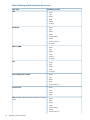
Revision History
Edition Date
Software
Description
Version
1
December 2009 5.3.1
Initial release of the IBRIX 9720 Storage.
2
April 2010
5.4
Added network management and Support ticket.
3
August 2010
5.4.1
Added Fusion Manager backup, migration to an agile Fusion Manager configuration,
software upgrade procedures, and system recovery procedures.
4
August 2010
5.4.1
Revised upgrade procedure.
5
December 2010 5.5
Added information about NDMP backups and configuring virtual interfaces, and updated
cluster procedures.
6
March 2011
5.5
Updated segment evacuation information.
7
April 2011
5.6
Revised upgrade procedure.
8
September 2011 6.0
Added or updated information about the agile Fusion Manager, Statistics tool, Ibrix
Collect, event notification, capacity block installation, NTP servers, upgrades.
9
June 2012
Added or updated information about 9730 systems, hardware monitoring, segment
evacuation, HP Insight Remote Support, software upgrades, events, Statistics tool.
10
December 2012 6.2
6.1
Added or updated information about High Availability, failover, server tuning, VLAN
tagging, segment migration and evacuation, upgrades, SNMP.
Contents
1 Product description...................................................................................12
System features.......................................................................................................................12
System components.................................................................................................................12
HP IBRIX software features.......................................................................................................12
High availability and redundancy.............................................................................................13
2 Getting started.........................................................................................14
Setting up the IBRIX 9720/9730 Storage...................................................................................14
Installation steps................................................................................................................14
Additional configuration steps.............................................................................................14
Logging in to the system..........................................................................................................15
Using the network..............................................................................................................15
Using the TFT keyboard/monitor..........................................................................................15
Using the serial link on the Onboard Administrator.................................................................16
Booting the system and individual server blades.........................................................................16
Management interfaces...........................................................................................................16
Using the GUI...................................................................................................................16
Customizing the GUI..........................................................................................................20
Adding user accounts for GUI access...................................................................................20
Using the CLI.....................................................................................................................21
Starting the array management software...............................................................................21
9000 client interfaces.........................................................................................................21
IBRIX software manpages........................................................................................................22
Changing passwords..............................................................................................................22
Configuring ports for a firewall.................................................................................................22
Configuring NTP servers..........................................................................................................23
Configuring HP Insight Remote Support on IBRIX 9000 systems.....................................................24
Configuring the IBRIX cluster for Insight Remote Support..........................................................25
Configuring Insight Remote Support for HP SIM 7.1 and IRS 5.7...............................................28
Configuring Insight Remote Support for HP SIM 6.3 and IRS 5.6..............................................30
Testing the Insight Remote Support configuration....................................................................33
Updating the Phone Home configuration...............................................................................33
Disabling Phone Home.......................................................................................................33
Troubleshooting Insight Remote Support................................................................................33
3 Configuring virtual interfaces for client access..............................................35
Network and VIF guidelines.....................................................................................................35
Creating a bonded VIF............................................................................................................36
Configuring backup servers......................................................................................................36
Configuring NIC failover.........................................................................................................36
Configuring automated failover................................................................................................37
Example configuration.............................................................................................................37
Specifying VIFs in the client configuration...................................................................................37
Configuring VLAN tagging......................................................................................................38
Support for link state monitoring...............................................................................................38
4 Configuring failover..................................................................................39
Agile management consoles....................................................................................................39
Agile Fusion Manager modes..............................................................................................39
Agile Fusion Manager and failover......................................................................................39
Viewing information about Fusion Managers.........................................................................40
Configuring High Availability on the cluster................................................................................40
What happens during a failover..........................................................................................40
Contents
3
Configuring automated failover with the HA Wizard...............................................................41
Configuring automated failover manually..............................................................................46
Changing the HA configuration manually.........................................................................48
Failing a server over manually.............................................................................................48
Failing back a server .........................................................................................................49
Setting up HBA monitoring..................................................................................................49
Checking the High Availability configuration.........................................................................51
Capturing a core dump from a failed node................................................................................52
Prerequisites for setting up the crash capture..........................................................................53
Setting up nodes for crash capture.......................................................................................53
5 Configuring cluster event notification...........................................................55
Cluster events.........................................................................................................................55
Setting up email notification of cluster events..............................................................................55
Associating events and email addresses................................................................................55
Configuring email notification settings..................................................................................56
Dissociating events and email addresses...............................................................................56
Testing email addresses......................................................................................................56
Viewing email notification settings........................................................................................56
Setting up SNMP notifications..................................................................................................57
Configuring the SNMP agent...............................................................................................57
Configuring trapsink settings................................................................................................58
Associating events and trapsinks..........................................................................................58
Defining views...................................................................................................................59
Configuring groups and users..............................................................................................59
Deleting elements of the SNMP configuration........................................................................60
Listing SNMP configuration information.................................................................................60
6 Configuring system backups.......................................................................61
Backing up the Fusion Manager configuration............................................................................61
Using NDMP backup applications............................................................................................61
Configuring NDMP parameters on the cluster........................................................................62
NDMP process management...............................................................................................62
Viewing or canceling NDMP sessions..............................................................................62
Starting, stopping, or restarting an NDMP Server..............................................................63
Viewing or rescanning tape and media changer devices.........................................................63
NDMP events....................................................................................................................64
7 Creating host groups for 9000 clients.........................................................65
How host groups work.............................................................................................................65
Creating a host group tree.......................................................................................................65
Adding an 9000 client to a host group.....................................................................................66
Adding a domain rule to a host group.......................................................................................66
Viewing host groups................................................................................................................66
Deleting host groups...............................................................................................................66
Other host group operations....................................................................................................67
8 Monitoring cluster operations.....................................................................68
Monitoring 9720/9730 hardware............................................................................................68
Monitoring servers.............................................................................................................68
Monitoring hardware components........................................................................................71
Monitoring blade enclosures...........................................................................................72
Obtaining server details.................................................................................................75
Monitoring storage and storage components.........................................................................78
Monitoring storage clusters.............................................................................................79
Monitoring drive enclosures for a storage cluster...........................................................80
Monitoring pools for a storage cluster.........................................................................82
4
Contents
Monitoring storage controllers for a storage cluster.......................................................84
Monitoring storage switches in a storage cluster................................................................85
Managing LUNs in a storage cluster................................................................................85
Monitoring the status of file serving nodes..................................................................................86
Monitoring cluster events.........................................................................................................87
Viewing events..................................................................................................................87
Removing events from the events database table....................................................................88
Monitoring cluster health.........................................................................................................88
Health checks....................................................................................................................88
Health check reports..........................................................................................................88
Viewing logs..........................................................................................................................90
Viewing and clearing the Integrated Management Log (IML).........................................................90
Viewing operating statistics for file serving nodes........................................................................90
9 Using the Statistics tool..............................................................................92
Installing and configuring the Statistics tool................................................................................92
Installing the Statistics tool...................................................................................................92
Enabling collection and synchronization................................................................................92
Upgrading the Statistics tool from IBRIX software 6.0...................................................................93
Using the Historical Reports GUI...............................................................................................93
Generating reports.............................................................................................................94
Deleting reports.................................................................................................................95
Maintaining the Statistics tool...................................................................................................95
Space requirements............................................................................................................95
Updating the Statistics tool configuration...............................................................................96
Changing the Statistics tool configuration..............................................................................96
Fusion Manager failover and the Statistics tool configuration...................................................96
Checking the status of Statistics tool processes.......................................................................97
Controlling Statistics tool processes.......................................................................................97
Troubleshooting the Statistics tool..............................................................................................97
Log files.................................................................................................................................98
Uninstalling the Statistics tool...................................................................................................98
10 Maintaining the system............................................................................99
Shutting down the system.........................................................................................................99
Shutting down the IBRIX software.........................................................................................99
Powering off the system hardware......................................................................................100
Starting up the system...........................................................................................................101
Powering on the system hardware......................................................................................101
Powering on after a power failure......................................................................................101
Starting the IBRIX software................................................................................................101
Powering file serving nodes on or off.......................................................................................101
Performing a rolling reboot....................................................................................................102
Starting and stopping processes.............................................................................................102
Tuning file serving nodes and 9000 clients..............................................................................102
Managing segments.............................................................................................................106
Migrating segments..........................................................................................................107
Evacuating segments and removing storage from the cluster ..................................................109
Removing a node from the cluster...........................................................................................112
Maintaining networks............................................................................................................112
Cluster and user network interfaces....................................................................................112
Adding user network interfaces..........................................................................................112
Setting network interface options in the configuration database..............................................113
Preferring network interfaces..............................................................................................114
Unpreferring network interfaces.........................................................................................115
Making network changes..................................................................................................115
Contents
5
Changing the IP address for a Linux 9000 client.............................................................115
Changing the cluster interface.......................................................................................115
Managing routing table entries.....................................................................................116
Adding a routing table entry....................................................................................116
Deleting a routing table entry...................................................................................116
Deleting a network interface.........................................................................................116
Viewing network interface information................................................................................116
11 Migrating to an agile Fusion Manager configuration..................................118
Backing up the configuration..................................................................................................118
Performing the migration........................................................................................................118
Testing failover and failback of the agile Fusion Manager..........................................................120
Converting the original management console node to a file serving node hosting the agile Fusion
Manager.............................................................................................................................121
12 Upgrading the IBRIX software to the 6.2 release.......................................122
Upgrading 9720 chassis firmware..........................................................................................124
Online upgrades for IBRIX software 6.x to 6.2..........................................................................124
Preparing for the upgrade.................................................................................................124
Performing the upgrade....................................................................................................124
After the upgrade............................................................................................................125
Automated offline upgrades for IBRIX software 6.x to 6.2...........................................................126
Preparing for the upgrade.................................................................................................126
Performing the upgrade....................................................................................................126
After the upgrade............................................................................................................127
Manual offline upgrades for IBRIX software 6.x to 6.2...............................................................128
Preparing for the upgrade.................................................................................................128
Performing the upgrade manually.......................................................................................129
After the upgrade............................................................................................................130
Upgrading Linux 9000 clients................................................................................................131
Installing a minor kernel update on Linux clients...................................................................132
Upgrading Windows 9000 clients..........................................................................................132
Troubleshooting upgrade issues..............................................................................................132
Automatic upgrade..........................................................................................................132
Manual upgrade.............................................................................................................133
Offline upgrade fails because iLO firmware is out of date......................................................133
Node is not registered with the cluster network ...................................................................133
File system unmount issues.................................................................................................134
13 Licensing.............................................................................................135
Viewing license terms............................................................................................................135
Retrieving a license key.........................................................................................................135
Using AutoPass to retrieve and install permanent license keys......................................................135
14 Upgrading firmware..............................................................................136
Components for firmware upgrades.........................................................................................136
Steps for upgrading the firmware............................................................................................137
Finding additional information on FMT...............................................................................140
Adding performance modules on 9730 systems...................................................................141
Adding new server blades on 9720 systems........................................................................141
15 Troubleshooting....................................................................................143
Collecting information for HP Support with Ibrix Collect.............................................................143
Collecting logs................................................................................................................143
Deleting the archive file....................................................................................................144
Downloading the archive file.............................................................................................144
Configuring Ibrix Collect...................................................................................................145
6
Contents
Viewing data collection information....................................................................................146
Viewing data collection configuration information................................................................146
Adding/deleting commands or logs in the XML file..............................................................146
Troubleshooting 9720 systems................................................................................................146
Escalating issues..............................................................................................................146
Useful utilities and processes.............................................................................................147
exds_stdiag utility........................................................................................................147
exds_netdiag utility.....................................................................................................148
exds_netperf utility......................................................................................................148
Accessing the Onboard Administrator.....................................................................................149
Accessing the OA through the network...............................................................................149
Access the OA Web-based administration interface.........................................................149
Accessing the OA through the serial port............................................................................150
Accessing the OA through the service port..........................................................................150
Using hpacucli – Array Configuration Utility (ACU)...............................................................150
POST error messages............................................................................................................150
IBRIX 9730 controller error messages......................................................................................150
IBRIX 9720 LUN layout..........................................................................................................153
IBRIX 9720 component monitoring..........................................................................................153
Identifying failed I/O modules on an X9700cx chassis..............................................................153
Failure indications............................................................................................................154
Identifying the failed component........................................................................................154
Re-seating an X9700c controller........................................................................................157
Viewing software version numbers..........................................................................................158
Troubleshooting specific issues................................................................................................158
Software services.............................................................................................................158
Failover..........................................................................................................................158
Windows 9000 clients.....................................................................................................159
Mode 1 or mode 6 bonding.............................................................................................159
Onboard Administrator is unresponsive...............................................................................160
IBRIX RPC call to host failed...............................................................................................160
Degrade server blade/Power PIC.......................................................................................160
LUN status is failed..........................................................................................................160
Apparent failure of HP P700m...........................................................................................161
X9700c enclosure front panel fault ID LED is amber..............................................................162
Replacement disk drive LED is not illuminated green.............................................................162
X9700cx GSI LED is amber...............................................................................................162
X9700cx drive LEDs are amber after firmware is flashed.......................................................162
Configuring the Virtual Connect domain..................................................................................162
Synchronizing information on file serving nodes and the configuration database...........................163
Troubleshooting an Express Query Manual Intervention Failure (MIF)...........................................163
16 Recovering the 9720/9730 Storage........................................................166
Obtaining the latest IBRIX software release...............................................................................166
Preparing for the recovery......................................................................................................166
Recovering a 9720 or 9730 file serving node...........................................................................167
Completing the restore .........................................................................................................173
Troubleshooting....................................................................................................................175
iLO remote console does not respond to keystrokes...............................................................175
17 Support and other resources...................................................................176
Contacting HP......................................................................................................................176
Related information...............................................................................................................176
HP websites.........................................................................................................................177
Rack stability........................................................................................................................177
Product warranties................................................................................................................177
Contents
7
Subscription service..............................................................................................................177
18 Documentation feedback.......................................................................178
A Cascading Upgrades.............................................................................179
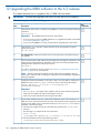
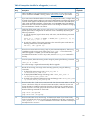
Upgrading the IBRIX software to the 6.1 release........................................................................179
Upgrading 9720 chassis firmware.....................................................................................179
Online upgrades for IBRIX software 6.x to 6.1......................................................................180
Preparing for the upgrade............................................................................................180
Performing the upgrade................................................................................................180
After the upgrade........................................................................................................181
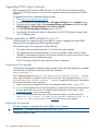
Offline upgrades for IBRIX software 5.6.x or 6.0.x to 6.1......................................................181
Preparing for the upgrade............................................................................................181
Performing the upgrade................................................................................................182
After the upgrade........................................................................................................183
Upgrading Linux 9000 clients............................................................................................184
Installing a minor kernel update on Linux clients..............................................................184
Upgrading Windows 9000 clients.....................................................................................184
Upgrading pre-6.0 file systems for software snapshots..........................................................185
Upgrading pre–6.1.1 file systems for data retention features...................................................186
Troubleshooting upgrade issues.........................................................................................186
Automatic upgrade......................................................................................................186
Manual upgrade.........................................................................................................187
Offline upgrade fails because iLO firmware is out of date.................................................187
Node is not registered with the cluster network ...............................................................187
File system unmount issues............................................................................................188
Moving the Fusion Manager VIF to bond1......................................................................188
Upgrading the IBRIX software to the 5.6 release.......................................................................189
Automatic upgrades.........................................................................................................190
Manual upgrades............................................................................................................190
Preparing for the upgrade............................................................................................190
Saving the node configuration......................................................................................191
Performing the upgrade................................................................................................191
Restoring the node configuration...................................................................................191
Completing the upgrade..............................................................................................191
Troubleshooting upgrade issues.........................................................................................192
Automatic upgrade......................................................................................................192
Manual upgrade.........................................................................................................193
Upgrading the IBRIX software to the 5.5 release.......................................................................193
Automatic upgrades.........................................................................................................194
Manual upgrades............................................................................................................194
Standard upgrade for clusters with a dedicated Management Server machine or blade........195
Standard online upgrade.........................................................................................195
Standard offline upgrade.........................................................................................196
Agile upgrade for clusters with an agile management console configuration.......................198
Agile online upgrade..............................................................................................199
Agile offline upgrade..............................................................................................202
Troubleshooting upgrade issues.........................................................................................205
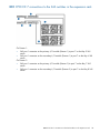
B IBRIX 9730 component and cabling diagrams............................................206
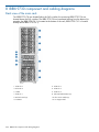
Back view of the main rack....................................................................................................206
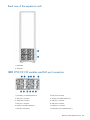
Back view of the expansion rack.............................................................................................207
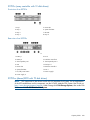
IBRIX 9730 CX I/O modules and SAS port connectors...............................................................207
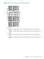
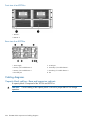
IBRIX 9730 CX 1 connections to the SAS switches.....................................................................208
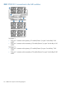
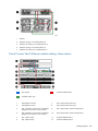
IBRIX 9730 CX 2 connections to the SAS switches.....................................................................209
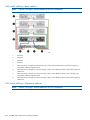
IBRIX 9730 CX 3 connections to the SAS switches.....................................................................210
8
Contents
IBRIX 9730 CX 7 connections to the SAS switches in the expansion rack......................................211
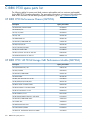
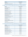
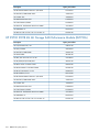
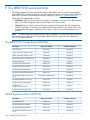
C IBRIX 9730 spare parts list ......................................................................212
HP
HP
HP
HP
HP
IBRIX 9730 Performance Chassis (QZ729A)........................................................................212
IBRIX 9730 140 TB MLStorage 2xBL Performance Module (QZ730A)......................................212
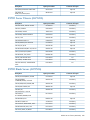
IBRIX 9730 210 TB ML Storage 2xBL Performance Module (QZ731A).....................................213
X9730 140 TB 6G ML Storage 2xBL Performance Module (QZ732A).....................................213
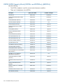
X9730 210TB 6G ML Storage 2xBL Performance Module (QZ733A)......................................214
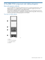
D The IBRIX 9720 component and cabling diagrams......................................215
Base and expansion cabinets.................................................................................................215
Front view of a base cabinet..............................................................................................215
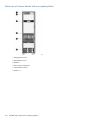
Back view of a base cabinet with one capacity block...........................................................216
Front view of a full base cabinet.........................................................................................217
Back view of a full base cabinet.........................................................................................218
Front view of an expansion cabinet ...................................................................................219
Back view of an expansion cabinet with four capacity blocks.................................................220
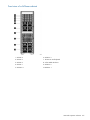
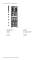
Performance blocks (c-Class Blade enclosure)............................................................................220
Front view of a c-Class Blade enclosure...............................................................................220
Rear view of a c-Class Blade enclosure...............................................................................221
Flex-10 networks...............................................................................................................221
Capacity blocks...................................................................................................................222
X9700c (array controller with 12 disk drives).......................................................................223
Front view of an X9700c..............................................................................................223
Rear view of an X9700c..............................................................................................223
X9700cx (dense JBOD with 70 disk drives)..........................................................................223
Front view of an X9700cx............................................................................................224
Rear view of an X9700cx.............................................................................................224
Cabling diagrams................................................................................................................224
Capacity block cabling—Base and expansion cabinets........................................................224
Virtual Connect Flex-10 Ethernet module cabling—Base cabinet.............................................225
SAS switch cabling—Base cabinet.....................................................................................226
SAS switch cabling—Expansion cabinet..............................................................................226
E The IBRIX 9720 spare parts list ................................................................228
The IBRIX 9720 Storage Base (AW548A).................................................................................228
X9700 Expansion Rack (AQ552A)..........................................................................................228
X9700 Server Chassis (AW549A)...........................................................................................229
X9700 Blade Server (AW550A).............................................................................................229
X9700 82TB Capacity Block (X9700c and X9700cx) (AQ551A).................................................230
X9700 164TB Capacity Block (X9700c and X9700cx) (AW598B)...............................................231
F Warnings and precautions.......................................................................233
Electrostatic discharge information..........................................................................................233
Preventing electrostatic discharge.......................................................................................233
Grounding methods.....................................................................................................233
Grounding methods.........................................................................................................233
Equipment symbols...............................................................................................................234
Weight warning...................................................................................................................234
Rack warnings and precautions..............................................................................................234
Device warnings and precautions...........................................................................................235
G Regulatory compliance notices................................................................237
Regulatory compliance identification numbers..........................................................................237
Federal Communications Commission notice............................................................................237
FCC rating label..............................................................................................................237
Class A equipment......................................................................................................237
Contents
9
Class B equipment......................................................................................................237
Modification...................................................................................................................238
Cables...........................................................................................................................238
Canadian notice (Avis Canadien)...........................................................................................238
Class A equipment...........................................................................................................238
Class B equipment...........................................................................................................238
European Union notice..........................................................................................................238
Japanese notices..................................................................................................................239
Japanese VCCI-A notice....................................................................................................239
Japanese VCCI-B notice....................................................................................................239
Japanese VCCI marking...................................................................................................239
Japanese power cord statement.........................................................................................239
Korean notices.....................................................................................................................239
Class A equipment...........................................................................................................239
Class B equipment...........................................................................................................239
Taiwanese notices.................................................................................................................240
BSMI Class A notice.........................................................................................................240
Taiwan battery recycle statement........................................................................................240
Turkish recycling notice..........................................................................................................240
Vietnamese Information Technology and Communications compliance marking.............................240
Laser compliance notices.......................................................................................................240
English laser notice..........................................................................................................240
Dutch laser notice............................................................................................................241
French laser notice...........................................................................................................241
German laser notice.........................................................................................................241
Italian laser notice............................................................................................................242
Japanese laser notice.......................................................................................................242
Spanish laser notice.........................................................................................................242
Recycling notices..................................................................................................................243
English recycling notice....................................................................................................243
Bulgarian recycling notice.................................................................................................243
Czech recycling notice......................................................................................................243
Danish recycling notice.....................................................................................................243
Dutch recycling notice.......................................................................................................243
Estonian recycling notice...................................................................................................244
Finnish recycling notice.....................................................................................................244
French recycling notice.....................................................................................................244
German recycling notice...................................................................................................244
Greek recycling notice......................................................................................................244
Hungarian recycling notice...............................................................................................244
Italian recycling notice......................................................................................................245
Latvian recycling notice.....................................................................................................245
Lithuanian recycling notice................................................................................................245
Polish recycling notice.......................................................................................................245
Portuguese recycling notice...............................................................................................245
Romanian recycling notice................................................................................................246
Slovak recycling notice.....................................................................................................246
Spanish recycling notice...................................................................................................246
Swedish recycling notice...................................................................................................246
Battery replacement notices...................................................................................................247
Dutch battery notice.........................................................................................................247
French battery notice........................................................................................................247
German battery notice......................................................................................................248
Italian battery notice........................................................................................................248
Japanese battery notice....................................................................................................249
10
Contents
Spanish battery notice......................................................................................................249
Glossary..................................................................................................250
Index.......................................................................................................252
Contents
11
1 Product description
HP 9720 and 9730 Storage are a scalable, network-attached storage (NAS) product. The system
combines HP IBRIX software with HP server and storage hardware to create a cluster of file serving
nodes.
System features
The 9720 and 9730 Storage provide the following features:
•
Segmented, scalable file system under a single namespace
•
NFS, SMB(Server Message Block), FTP, and HTTP support for accessing file system data
•
Centralized CLI and GUI for cluster management
•
Policy management
•
Continuous remote replication
•
Dual redundant paths to all storage components
•
Gigabytes-per-second of throughput
IMPORTANT: It is important to keep regular backups of the cluster configuration. See “Backing
up the Fusion Manager configuration” (page 61) for more information.
System components
IMPORTANT: All software included with the IBRIX 9720/9730 Storage is for the sole purpose
of operating the system. Do not add, remove, or change any software unless instructed to do so
by HP-authorized personnel.
For information about 9730 system components and cabling, see “IBRIX 9730 component and
cabling diagrams” (page 206).
For information about 9720 system components and cabling, see “The IBRIX 9720 component
and cabling diagrams” (page 215).
For a complete list of system components, see the HP IBRIX 9000 Storage QuickSpecs, which are
available at:
http://www.hp.com/go/StoreAll
HP IBRIX software features
HP IBRIX software is a scale-out, network-attached storage solution including a parallel file system
for clusters, an integrated volume manager, high-availability features such as automatic failover
of multiple components, and a centralized management interface. IBRIX software can scale to
thousands of nodes.
Based on a segmented file system architecture, IBRIX software integrates I/O and storage systems
into a single clustered environment that can be shared across multiple applications and managed
from a central Fusion Manager.
IBRIX software is designed to operate with high-performance computing applications that require
high I/O bandwidth, high IOPS throughput, and scalable configurations.
Some of the key features and benefits are as follows:
12
•
Scalable configuration. You can add servers to scale performance and add storage devices
to scale capacity.
•
Single namespace. All directories and files are contained in the same namespace.
Product description
•
Multiple environments. Operates in both the SAN and DAS environments.
•
High availability. The high-availability software protects servers.
•
Tuning capability. The system can be tuned for large or small-block I/O.
•
Flexible configuration. Segments can be migrated dynamically for rebalancing and data
tiering.
High availability and redundancy
The segmented architecture is the basis for fault resilience—loss of access to one or more segments
does not render the entire file system inaccessible. Individual segments can be taken offline
temporarily for maintenance operations and then returned to the file system.
To ensure continuous data access, IBRIX software provides manual and automated failover protection
at various points:
•
Server. A failed node is powered down and a designated standby server assumes all of its
segment management duties.
•
Segment. Ownership of each segment on a failed node is transferred to a designated standby
server.
•
Network interface. The IP address of a failed network interface is transferred to a standby
network interface until the original network interface is operational again.
•
Storage connection. For servers with HBA-protected Fibre Channel access, failure of the HBA
triggers failover of the node to a designated standby server.
High availability and redundancy
13
2 Getting started
This chapter describes how to log in to the system, boot the system and individual server blades,
change passwords, and back up the Fusion Manager configuration. It also describes the IBRIX
software management interfaces.
IMPORTANT:
Follow these guidelines when using your system:
•
Do not modify any parameters of the operating system or kernel, or update any part of the
IBRIX 9720/9730 Storage unless instructed to do so by HP; otherwise, the system could fail
to operate properly.
•
File serving nodes are tuned for file serving operations. With the exception of supported
backup programs, do not run other applications directly on the nodes.
Setting up the IBRIX 9720/9730 Storage
An HP service specialist sets up the system at your site, including the following tasks:
Installation steps
•
Before starting the installation, ensure that the product components are in the location where
they will be installed. Remove the product from the shipping cartons, confirm the contents of
each carton against the list of included items, check for any physical damage to the exterior
of the product, and connect the product to the power and network provided by you.
•
Review your server, network, and storage environment relevant to the HP Enterprise NAS
product implementation to validate that prerequisites have been met.
•
Validate that your file system performance, availability, and manageability requirements have
not changed since the service planning phase. Finalize the HP Enterprise NAS product
implementation plan and software configuration.
•
Implement the documented and agreed-upon configuration based on the information you
provided on the pre-delivery checklist.
•
Document configuration details.
Additional configuration steps
When your system is up and running, you can continue configuring the cluster and file systems.
The Management Console GUI and CLI are used to perform most operations. (Some features
described here may be configured for you as part of the system installation.)
Cluster. Configure the following as needed:
14
•
Firewall ports. See “Configuring ports for a firewall” (page 22)
•
HP Insight Remote Support and Phone Home. See “Configuring HP Insight Remote Support
on IBRIX 9000 systems” (page 24).
•
Virtual interfaces for client access. See “Configuring virtual interfaces for client access”
(page 35).
•
Cluster event notification through email or SNMP. See “Configuring cluster event notification”
(page 55).
•
Fusion Manager backups. See “Backing up the Fusion Manager configuration” (page 61).
•
NDMP backups. See “Using NDMP backup applications” (page 61).
•
Statistics tool. See “Using the Statistics tool” (page 92).
•
Ibrix Collect. See “Collecting information for HP Support with Ibrix Collect” (page 143).
Getting started
File systems. Set up the following features as needed:
•
NFS, SMB (Server Message Block), FTP, or HTTP. Configure the methods you will use to access
file system data.
•
Quotas. Configure user, group, and directory tree quotas as needed.
•
Remote replication. Use this feature to replicate changes in a source file system on one cluster
to a target file system on either the same cluster or a second cluster.
•
Data retention and validation. Use this feature to manage WORM and retained files.
•
Antivirus support. This feature is used with supported Antivirus software, allowing you to scan
files on an IBRIX file system.
•
IBRIX software snapshots. This feature allows you to capture a point-in-time copy of a file
system or directory for online backup purposes and to simplify recovery of files from accidental
deletion. Users can access the file system or directory as it appeared at the instant of the
snapshot.
•
File allocation. Use this feature to specify the manner in which segments are selected for storing
new files and directories.
•
Data tiering. Use this feature to move files to specific tiers based on file attributes.
For more information about these file system features, see the HP IBRIX 9000 Storage File System
User Guide.
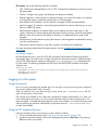
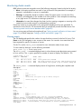
Localization support
Red Hat Enterprise Linux 5 uses the UTF-8 (8-bit Unicode Transformation Format) encoding for
supported locales. This allows you to create, edit and view documents written in different locales
using UTF-8. IBRIX software supports modifying the /etc/sysconfig/i18n configuration file
for your locale. The following example sets the LANG and SUPPORTED variables for multiple
character sets:
LANG="ko_KR.utf8"
SUPPORTED="en_US.utf8:en_US:en:ko_KR.utf8:ko_KR:ko:zh_CN.utf8:zh_CN:zh"
SYSFONT="lat0-sun16"
SYSFONTACM="iso15"
Logging in to the system
Using the network
Use ssh to log in remotely from another host. You can log in to any server using any configured
site network interface (eth1, eth2, or bond1).
With ssh and the root user, after you log in to any server, your .ssh/known_hosts file will
work with any server in the cluster.
The original server blades in your cluster are configured to support password-less ssh. After you
have connected to one server, you can connect to the other servers without specifying the root
password again. To enable the same support for other server blades, or to access the system itself
without specifying a password, add the keys of the other servers to .ssh/authorized keys
on each server blade.
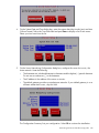
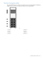
Using the TFT keyboard/monitor
If the site network is down, you can log in to the console as follows:
1. Pull out the keyboard monitor (See “Front view of a base cabinet” (page 215)).
2. Access the on-screen display (OSD) main dialog box by pressing Print Scrn or by pressing
Ctrl twice within one second.
Logging in to the system
15
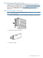
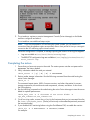
3.
4.
Double-click the first server name.
Log in as normal.
NOTE: By default, the first port is connected with the dongle to the front of blade 1 (that is, server
1). If server 1 is down, move the dongle to another blade.
Using the serial link on the Onboard Administrator
If you are connected to a terminal server, you can log in through the serial link on the Onboard
Administrator.
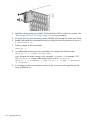
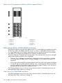
Booting the system and individual server blades
Before booting the system, ensure that all of the system components other than the server blades—the
capacity blocks or performance modules and so on—are turned on. By default, server blades boot
whenever power is applied to the system performance chassis (c-Class Blade enclosure). If all server
blades are powered off, you can boot the system as follows:
1. Press the power button on server blade 1.
2. Log in as root to server 1.
3. Power on the remaining server blades:
ibrix_server -P on -h <hostname>
NOTE: Alternatively, press the power button on all of the remaining servers. There is no
need to wait for the first server blade to boot.
Management interfaces
Cluster operations are managed through the IBRIX Fusion Manager, which provides both a GUI
and a CLI. Most operations can be performed from either the GUI or the CLI.
The following operations can be performed only from the CLI:
•
SNMP configuration (ibrix_snmpagent, ibrix_snmpgroup, ibrix_snmptrap,
ibrix_snmpuser, ibrix_snmpview)
•
Health checks (ibrix_haconfig, ibrix_health, ibrix_healthconfig)
•
Raw storage management (ibrix_pv, ibrix_vg, ibrix_lv)
•
Fusion Manager operations (ibrix_fm) and Fusion Manager tuning (ibrix_fm_tune)
•
File system checks (ibrix_fsck)
•
Kernel profiling (ibrix_profile)
•
Cluster configuration (ibrix_clusterconfig)
•
Configuration database consistency (ibrix_dbck)
•
Shell task management (ibrix_shell)
The following operations can be performed only from the GUI:
•
Scheduling recurring data validation scans
•
Scheduling recurring software snapshots
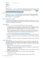
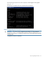
Using the GUI
The GUI is a browser-based interface to the Fusion Manager. See the release notes for the supported
browsers and other software required to view charts on the dashboard. You can open multiple
GUI windows as necessary.
16
Getting started
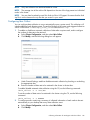
If you are using HTTP to access the GUI, open a web browser and navigate to the following
location, specifying port 80:
http://<management_console_IP>:80/fusion
If you are using HTTPS to access the GUI, navigate to the following location, specifying port 443:
https://<management_console_IP>:443/fusion
In these URLs, <management_console_IP> is the IP address of the Fusion Manager user VIF.
The GUI prompts for your user name and password. The default administrative user is ibrix.
Enter the password that was assigned to this user when the system was installed. (You can change
the password using the Linux passwd command.) To allow other users to access the GUI, see
“Adding user accounts for GUI access” (page 20).
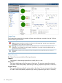
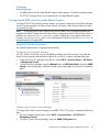
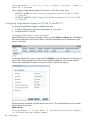
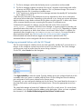
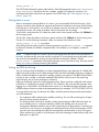
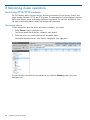
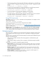
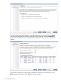
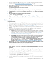
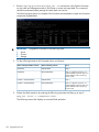
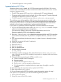
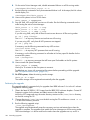
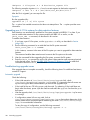
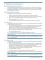
Upon login, the GUI dashboard opens, allowing you to monitor the entire cluster. (See the online
help for information about all GUI displays and operations.) There are three parts to the dashboard:
System Status, Cluster Overview, and the Navigator.
Management interfaces
17
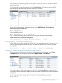
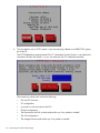
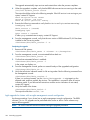
System Status
The System Status section lists the number of cluster events that have occurred in the last 24 hours.
There are three types of events:
Alerts. Disruptive events that can result in loss of access to file system data. Examples are a segment that is
unavailable or a server that cannot be accessed.
Warnings. Potentially disruptive conditions where file system access is not lost, but if the situation is not
addressed, it can escalate to an alert condition. Examples are a very high server CPU utilization level or a
quota limit close to the maximum.
Information. Normal events that change the cluster. Examples are mounting a file system or creating a
segment.
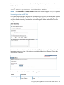
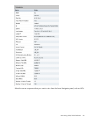
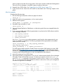
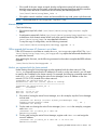
Cluster Overview
The Cluster Overview provides the following information:
Capacity
The amount of cluster storage space that is currently free or in use.
File systems
The current health status of the file systems in the cluster. The overview reports the number of
file systems in each state (healthy, experiencing a warning, experiencing an alert, or unknown).
Segment Servers
The current health status of the file serving nodes in the cluster. The overview reports the number
of nodes in each state (healthy, experiencing a warning, experiencing an alert, or unknown).
18
Getting started
Services
Whether the specified file system services are currently running:
One or more tasks are
running.
No tasks are running.
Statistics
Historical performance graphs for the following items:
•
Network I/O (MB/s)
•
Disk I/O (MB/s)
•
CPU usage (%)
•
Memory usage (%)
On each graph, the X-axis represents time and the Y-axis represents performance.
Use the Statistics menu to select the servers to monitor (up to two), to change the maximum
value for the Y-axis, and to show or hide resource usage distribution for CPU and memory.
Recent Events
The most recent cluster events. Use the Recent Events menu to select the type of events to display.
You can also access certain menu items directly from the Cluster Overview. Mouse over the
Capacity, Filesystems or Segment Server indicators to see the available options.
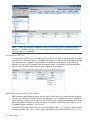
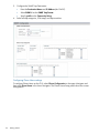
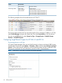
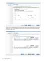
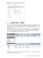
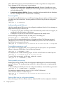
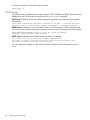
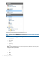
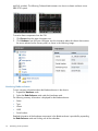
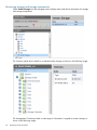
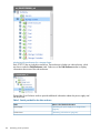
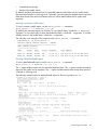
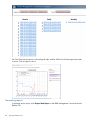
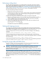
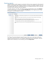
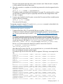
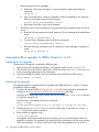
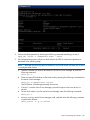
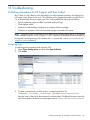
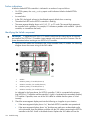
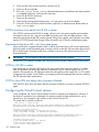
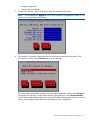
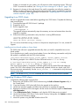
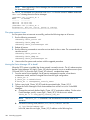
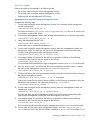
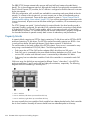
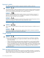
Navigator
The Navigator appears on the left side of the window and displays the cluster hierarchy. You can
use the Navigator to drill down in the cluster configuration to add, view, or change cluster objects
such as file systems or storage, and to initiate or view tasks such as snapshots or replication. When
you select an object, a details page shows a summary for that object. The lower Navigator allows
you to view details for the selected object, or to initiate a task. In the following example, we selected
Filesystems in the upper Navigator and Mountpoints in the lower Navigator to see details about
the mounts for file system ifs1.
Management interfaces
19
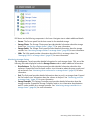
NOTE: When you perform an operation on the GUI, a spinning finger is displayed until the
operation is complete. However, if you use Windows Remote Desktop to access the GUI, the
spinning finger is not displayed.
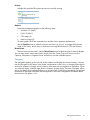
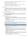
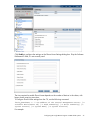
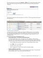
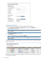
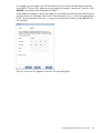
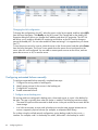
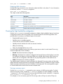
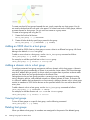
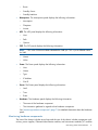
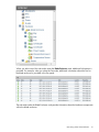
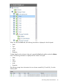
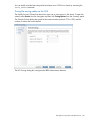
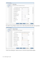
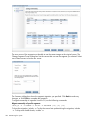
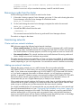
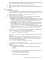
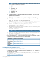
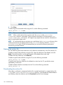
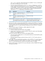
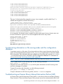
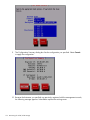
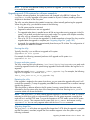
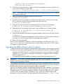
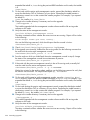
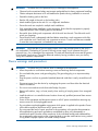
Customizing the GUI
For most tables in the GUI, you can specify the columns that you want to display and the sort order
of each column. When this feature is available, mousing over a column causes the label to change
color and a pointer to appear. Click the pointer to see the available options. In the following
example, you can sort the contents of the Mountpoint column in ascending or descending order,
and you can select the columns that you want to appear in the display.
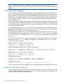
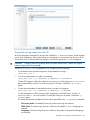
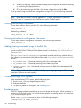
Adding user accounts for GUI access
IBRIX software supports administrative and user roles. When users log in under the administrative
role, they can configure the cluster and initiate operations such as remote replication or snapshots.
When users log in under the user role, they can view the cluster configuration and status, but cannot
make configuration changes or initiate operations. The default administrative user name is ibrix.
The default regular username is ibrixuser.
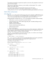
User names for the administrative and user roles are defined in the /etc/group file. Administrative
users are specified in the ibrix-admin group, and regular users are specified in the ibrix-user
20
Getting started
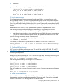
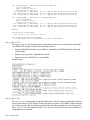
group. These groups are created when IBRIX software is installed. The following entries in the
/etc/group file show the default users in these groups:
ibrix-admin:x:501:root,ibrix
ibrix-user:x:502:ibrix,ibrixUser,ibrixuser
You can add other users to these groups as needed, using Linux procedures. For example:
adduser -G ibrix-<groupname> <username>
When using the adduser command, be sure to include the -G option.
Using the CLI
The administrative commands described in this guide must be executed on the Fusion Manager
host and require root privileges. The commands are located in $IBRIXHOME⁄bin. For complete
information about the commands, see the HP IBRIX 9000 Network Storage System CLI Reference
Guide.
When using ssh to access the machine hosting the Fusion Manager, specify the IP address of the
Fusion Manager user VIF.
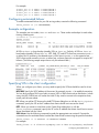
Starting the array management software
Depending on the array type, you can launch the array management software from the GUI. In
the Navigator, select Vendor Storage, select your array from the Vendor Storage page, and click
Launch Storage Management.
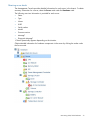
9000 client interfaces
9000 clients can access the Fusion Manager as follows:
•
Linux clients. Use Linux client commands for tasks such as mounting or unmounting file systems
and displaying statistics. See the HP IBRIX 9000 Storage CLI Reference Guide for details about
these commands.
•
Windows clients. Use the Windows client GUI for tasks such as mounting or unmounting file
systems and registering Windows clients.
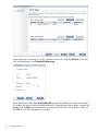
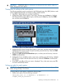
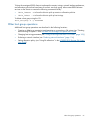
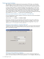
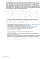
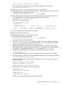
Using the Windows 9000 client GUI
The Windows 9000 client GUI is the client interface to the Fusion Manager. To open the GUI,
double-click the desktop icon or select the 9000 client program from the Start menu on the client.
The client program contains tabs organized by function.
NOTE:
The Windows 9000 client GUI can be started only by users with Administrative privileges.
•
Status. Shows the client’s Fusion Manager registration status and mounted file systems, and
provides access to the IAD log for troubleshooting.
•
Registration. Registers the client with the Fusion Manager, as described in the HP IBRIX 9000
Storage Installation Guide.
•
Mount. Mounts a file system. Select the Cluster Name from the list (the cluster name is the
Fusion Manager name), enter the name of the file system to mount, select a drive, and then
click Mount. (If you are using Remote Desktop to access the client and the drive letter does
not appear, log out and log in again.)
•
Umount. Unmounts a file system.
•
Tune Host. Tunable parameters include the NIC to prefer (the client uses the cluster interface
by default unless a different network interface is preferred for it), the communications protocol
(UDP or TCP), and the number of server threads to use.
•
Active Directory Settings. Displays current Active Directory settings.
Management interfaces
21
For more information, see the client GUI online help.
IBRIX software manpages
IBRIX software provides manpages for most of its commands. To view the manpages, set the
MANPATH variable to include the path to the manpages and then export it. The manpages are in
the $IBRIXHOME/man directory. For example, if $IBRIXHOME is /usr/local/ibrix (the
default), set the MANPATH variable as follows and then export the variable:
MANPATH=$MANPATH:/usr/local/ibrix/man
Changing passwords
IMPORTANT: The hpspAdmin user account is added during the IBRIX software installation and
is used internally. Do not remove this account or change its password.
You can change the following passwords on your system:
•
Hardware passwords. See the documentation for the specific hardware for more information.
•
Root password. Use the passwd(8) command on each server.
•
IBRIX software user password. This password is created during installation and is used to log
in to the GUI. The default is ibrix. You can change the password using the Linux passwd
command.
# passwd ibrix
You will be prompted to enter the new password.
Configuring ports for a firewall
IMPORTANT: To avoid unintended consequences, HP recommends that you configure the firewall
during scheduled maintenance times.
When configuring a firewall, you should be aware of the following:
•
SELinux should be disabled.
•
By default, NFS uses random port numbers for operations such as mounting and locking.
These ports must be fixed so that they can be listed as exceptions in a firewall configuration
file. For example, you will need to lock specific ports for rpc.statd, rpc.lockd,
rpc.mountd, and rpc.quotad.
•
It is best to allow all ICMP types on all networks; however, you can limit ICMP to types 0, 3,
8, and 11 if necessary.
Be sure to open the ports listed in the following table.
Port
Description
22/tcp
SSH
9022/tcp
SSH for Onboard Administrator (OA); only for 9720/9730 blades
123/tcp, 123/upd
NTP
5353/udp
Multicast DNS, 224.0.0.251
12865/tcp
netperf tool
80/tcp
Fusion Manager to file serving nodes
443/tcp
5432/tcp
22
Getting started
Fusion Manager and IBRIX file system
Port
Description
8008/tcp
9002/tcp
9005/tcp
9008/tcp
9009/tcp
9200/tcp
Between file serving nodes and NFS clients (user network)
2049/tcp, 2049/udp
NFS
111/tcp, 111/udp
RPC
875/tcp, 875/udp
quota
32803/tcp
lockmanager
32769/udp
lockmanager
892/tcp, 892/udp
mount daemon
662/tcp, 662/udp
stat
2020/tcp, 2020/udp
stat outgoing
4000:4003/tcp
reserved for use by a custom application (CMU) and can be disabled if not used
137/udp
Between file serving nodes and SMB clients (user network)
138/udp
139/tcp
445/tcp
9000:9002/tcp
Between file serving nodes and 9000 clients (user network)
9000:9200/udp
20/tcp, 20/udp
Between file serving nodes and FTP clients (user network)
21/tcp, 21/udp
7777/tcp
Between GUI and clients that need to access the GUI
8080/tcp
5555/tcp, 5555/udp
Dataprotector
631/tcp, 631/udp
Internet Printing Protocol (IPP)
1344/tcp, 1344/udp
ICAP
Configuring NTP servers
When the cluster is initially set up, primary and secondary NTP servers are configured to provide
time synchronization with an external time source. The list of NTP servers is stored in the Fusion
Manager configuration. The active Fusion Manager node synchronizes its time with the external
source. The other file serving nodes synchronize their time with the active Fusion Manager node.
In the absence of an external time source, the local hardware clock on the agile Fusion Manager
node is used as the time source. This configuration method ensures that the time is synchronized
on all cluster nodes, even in the absence of an external time source.
On 9000 clients, the time is not synchronized with the cluster nodes. You will need to configure
NTP servers on 9000 clients.
List the currently configured NTP servers:
ibrix_clusterconfig -i -N
Specify a new list of NTP servers:
Configuring NTP servers
23
ibrix_clusterconfig -c -N SERVER1[,...,SERVERn]
Configuring HP Insight Remote Support on IBRIX 9000 systems
IMPORTANT: In the IBRIX software 6.1 release, the default port for the IBRIX SNMP agent changed
from 5061 to 161. This port number cannot be changed.
Prerequisites
The required components for supporting IBRIX systems are preinstalled on the file serving nodes.
You must install HP Insight Remote Support on a separate Windows system termed the Central
Management Server (CMS):
•
HP Insight Manager (HP SIM). This software manages HP systems and is the easiest and least
expensive way to maximize system uptime and health.
•
Insight Remote Support Advanced (IRSA). This version is integrated with HP Systems Insight
Manager (SIM). It provides comprehensive remote monitoring, notification/advisories, dispatch,
and proactive service support. IRSA and HP SIM together are referred to as the CMS.
The following versions of the software are supported.
•
HP SIM 6.3 and IRSA 5.6
•
HP SIM 7.1 and IRSA 5.7
IMPORTANT:
and later.
Insight Remote Support Standard (IRSS ) is not supported with IBRIX software 6.1
For product descriptions and information about downloading the software, see the HP Insight
Remote Support Software web page:
http://www.hp.com/go/insightremotesupport
For information about HP SIM:
http://www.hp.com/products/systeminsightmanager
For IRSA documentation:
http://www.hp.com/go/insightremoteadvanced-docs
IMPORTANT: You must compile and manually register the IBRIX MIB file by using HP Systems
Insight Manager:
1. Download ibrixMib.txt from /usr/local/ibrix/doc/.
2. Rename the file to ibrixMib.mib.
3. In HP Systems Insight Manager, complete the following steps:
a. Unregister the existing MIB by entering the following command:
<BASE>\mibs>mxmib -d ibrixMib.mib
b.
Copy the ibrixMib.mib file to the <BASE>\mibs directory, and then enter the following
commands:
<BASE>\mibs>mcompile ibrixMib.mib
<BASE>\mibs>mxmib -a ibrixMib.cfg
For more information about the MIB, see the "Compiling and customizing MIBs" chapter in the HP
Systems Insight Manager User Guide, which is available at:
http://www.hp.com/go/insightmanagement/sim/
Click Support & Documents and then click Manuals. Navigate to the user guide.
24
Getting started
Limitations
Note the following:
•
For IBRIX systems, the HP Insight Remote Support implementation is limited to hardware events.
•
The 9720 CX storage device is not supported for HP Insight Remote Support.
Configuring the IBRIX cluster for Insight Remote Support
To enable 9720/9730 systems for remote support, you need to configure the Virtual SAS Manager,
Virtual Connect Manager, and Phone Home settings. All nodes in the cluster should be up when
you perform this step.
NOTE: Configuring Phone Home removes any previous IBRIX snmp configuration details and
populates the SNMP configuration with Phone Home configuration details. When Phone Home is
enabled, you cannot use ibrix_snmpagent to edit or change the snmp agent configuration.
However, you can use ibrix_snmptrap to add trapsink IPs and you can use ibrix_event to
associate events to the trapsink IPs.
Registering Onboard Administrator
The Onboard Administrator is registered automatically.
Configuring the Virtual SAS Manager
On 9730 systems, the SNMP service is disabled by default on the SAS switches. To enable the
SNMP service manually and provide the trapsink IP on all SAS switches, complete these steps:
1. Open the Virtual SAS Manager from the OA. Select OA IP > Interconnet Bays > SAS Switch
> Management Console.
2. On the Virtual SAS Manager, open the Maintain tab, click SAS Blade Switch, and select SNMP
Settings. On the dialog box, enable the SNMP service and supply the information needed for
alerts.
Configuring the Virtual Connect Manager
To configure the Virtual Connect Manager on an IBRIX 9720/9730 system, complete the following
steps:
1. From the Onboard Administrator, select OA IP > Interconnet Bays > HP VC Flex-10 >
Management Console.
2. On the HP Virtual Connect Manager, open the SNMP Configuration tab.
Configuring HP Insight Remote Support on IBRIX 9000 systems
25
3.
4.
Configure the SNMP Trap Destination:
•
Enter the Destination Name and IP Address (the CMS IP).
•
Select SNMPv1 as the SNMP Trap Format.
•
Specify public as the Community String.
Select all trap categories, VCM traps, and trap severities.
Configuring Phone Home settings
To configure Phone Home on the GUI, select Cluster Configuration in the upper Navigator and
then select Phone Home in the lower Navigator. The Phone Home Setup panel shows the current
configuration.
26
Getting started
Click Enable to configure the settings on the Phone Home Settings dialog box. Skip the Software
Entitlement ID field; it is not currently used.
The time required to enable Phone Home depends on the number of devices in the cluster, with
larger clusters requiring more time.
To configure Phone Home settings from the CLI, use the following command:
ibrix_phonehome -c -i <IP Address of the Central Management Server> [-z
Software Entitlement Id] [-r Read Community] [-w Write Community] [-t
System Contact] [-n System Name] [-o System Location]
For example:
Configuring HP Insight Remote Support on IBRIX 9000 systems
27
ibrix_phonehome -c -i 99.2.4.75 -P US -r public -w private -t Admin -n
SYS01.US -o Colorado
Next, configure Insight Remote Support for the version of HP SIM you are using:
•
HP SIM 7.1 and IRS 5.7. See “Configuring Insight Remote Support for HP SIM 7.1 and IRS
5.7” (page 28).
•
HP SIM 6.3 and IRS 5.6. See “Configuring Insight Remote Support for HP SIM 6.3 and IRS
5.6” (page 30).
Configuring Insight Remote Support for HP SIM 7.1 and IRS 5.7
To configure Insight Remote Support, complete these steps:
1. Configure Entitlements for the servers and chassis in your system.
2. Discover devices on HP SIM.
Configuring Entitlements for servers and chassis
Expand Phone Home in the lower Navigator. When you select Chassis or Servers, the GUI displays
the current Entitlements for that type of device. The following example shows Entitlements for the
servers in the cluster.
To configure Entitlements, select a device and click Modify to open the dialog box for that type of
device. The following example shows the Server Entitlement dialog box. The customer-entered
serial number and product number are used for warranty checks at HP Support.
Use the following commands to entitle devices from the CLI. The commands must be run for each
device present in the cluster.
Entitle a server:
ibrix_phonehome -e -h <Host Name> -b <Customer Entered Serial Number>
-g <Customer Entered Product Number>
28
Getting started
Enter the Host Name parameter exactly as it is listed by the ibrix_fm -l command.
Entitle a chassis:
ibrix_phonehome -e -C <OA IP Address of the Chassis> -b <Customer Entered
Serial Number> -g <Customer Entered Product Number>
NOTE:
The Phone Home > Storage selection on the GUI does not apply to 9720/9730 systems.
Discovering devices on HP SIM
HP Systems Insight Manager (SIM) uses the SNMP protocol to discover and identify IBRIX systems
automatically. On HP SIM, open Options > Discovery > New. Select Discover a group of systems,
and then enter the discovery name and the Fusion Manager IP address on the New Discovery
dialog box.
Enter the read community string on the Credentials > SMTP tab. This string should match the Phone
Home read community string. If the strings are not identical, the Fusion Manager IP might be
discovered as “Unknown.”
Devices are discovered as described in the following table.
Device
Discovered as
Fusion Manager IP
System Type:
System Subtype:
nl
Fusion Manager
9000
nl
nl
nl
Configuring HP Insight Remote Support on IBRIX 9000 systems
29
Device
Discovered as
File serving nodes
Product Model:
HP 9000 Solution
System Type:
System Subtype:
Product Model:
Storage Device
9000, Storage, HP ProLiant
HP 9720 NetStor FSN(ProLiant BL460 G6)
HP 9720 NetStor FSN(ProLiant BL460 G6)
HP 9730 NetStor FSN(ProLiant BL460 G7)
HP 9730 NetStor FSN(ProLiant BL460 G7)
nl
nl
nl
nl
nl
nl
nl
nl
The following example shows discovered devices on HP SIM 7.1.
File serving nodes and the OA IP are associated with the Fusion Manager IP address. In HP SIM,
select Fusion Manager and open the Systems tab. Then select Associations to view the devices.
You can view all IBRIX devices under Systems by Type > Storage System > Scalable Storage
Solutions > All X9000 Systems
Configuring Insight Remote Support for HP SIM 6.3 and IRS 5.6
Discovering devices in HP SIM
HP Systems Insight Manager (SIM) uses the SNMP protocol to discover and identify IBRIX systems
automatically. On HP SIM, open Options > Discovery > New, and then select Discover a group of
systems. On the Edit Discovery dialog box, enter the discovery name and the IP addresses of the
devices to be monitored. For more information, see the HP SIM 6.3 documentation.
NOTE:
30
Getting started
Each device in the cluster should be discovered separately.
Enter the read community string on the Credentials > SMTP tab. This string should match the Phone
Home read community string. If the strings are not identical, the device will be discovered as
“Unknown.”
The following example shows discovered devices on HP SIM 6.3. File serving nodes are discovered
as ProLiant server.
Configuring device Entitlements
Configure the CMS software to enable remote support for IBRIX systems. For more information,
see "Using the Remote Support Setting Tab to Update Your Client and CMS Information” and
“Adding Individual Managed Systems” in the HP Insight Remote Support Advanced A.05.50
Operations Guide.
Enter the following custom field settings in HP SIM:
•
Custom field settings for 9720/9730 Onboard Administrator
The Onboard Administrator (OA) is discovered with OA IP addresses. When the OA is
discovered, edit the system properties on the HP Systems Insight Manager. Locate the Entitlement
Information section of the Contract and Warranty Information page and update the following:
•
◦
Enter the IBRIX enclosure product number as the Customer-Entered product number
◦
Enter 9000 as the Custom Delivery ID
◦
Select the System Country Code
◦
Enter the appropriate Customer Contact and Site Information details
Contract and Warranty Information
Under Entitlement Information, specify the Customer-Entered serial number, Customer-Entered
product number, System Country code, and Custom Delivery ID.
Configuring HP Insight Remote Support on IBRIX 9000 systems
31
Verifying device entitlements
To verify the entitlement information in HP SIM, complete the following steps:
1. Go to Remote Support Configuration and Services and select the Entitlement tab.
2. Check the devices discovered.
NOTE: If the system discovered on HP SIM does not appear on the Entitlement tab, click
Synchronize RSE.
3.
4.
5.
Select Entitle Checked from the Action List.
Click Run Action.
When the entitlement check is complete, click Refresh.
NOTE: If the system discovered on HP SIM does not appear on the Entitlement tab, click
Synchronize RSE.
The devices you entitled should be displayed as green in the ENT column on the Remote Support
System List dialog box.
If a device is red, verify that the customer-entered serial number and part number are correct and
then rediscover the devices.
32
Getting started
Testing the Insight Remote Support configuration
To determine whether the traps are working properly, send a generic test trap with the following
command:
snmptrap -v1 -c public <CMS IP> .1.3.6.1.4.1.232 <Managed System IP> 6
11003 1234 .1.3.6.1.2.1.1.5.0 s test .1.3.6.1.4.1.232.11.2.11.1.0 i 0
.1.3.6.1.4.1.232.11.2.8.1.0 s "IBRIX remote support testing"
For example, if the CMS IP address is 99.2.2.2 and the IBRIX node is 99.2.2.10, enter the following:
snmptrap -v1 -c public 99.2.2.2 .1.3.6.1.4.1.232 99.2.2.10 6 11003 1234
.1.3.6.1.2.1.1.5.0 s test .1.3.6.1.4.1.232.11.2.11.1.0 i 0
.1.3.6.1.4.1.232.11.2.8.1.0 s "IBRIX remote support testing"
Updating the Phone Home configuration
The Phone Home configuration should be synchronized after you add or remove devices in the
cluster. The operation enables Phone Home on newly added devices (servers, storage, and chassis)
and removes details for devices that are no longer in the cluster. On the GUI, select Cluster
Configuration in the upper Navigator, select Phone Home in the lower Navigator, and click Rescan
on the Phone Home Setup panel.
On the CLI, run the following command:
ibrix_phonehome –s
Disabling Phone Home
When Phone Home is disabled, all Phone Home information is removed from the cluster and
hardware and software are no longer monitored. To disable Phone Home on the GUI, click Disable
on the Phone Home Setup panel. On the CLI, run the following command:
ibrix_phonehome -d
Troubleshooting Insight Remote Support
Devices are not discovered on HP SIM
Verify that cluster networks and devices can access the CMS. Devices will not be discovered
properly if they cannot access the CMS.
The maximum number of SNMP trap hosts has already been configured
If this error is reported, the maximum number of trapsink IP addresses have already been configured.
For OA devices, the maximum number of trapsink IP addresses is 8. Manually remove a trapsink
IP address from the device and then rerun the Phone Home configuration to allow Phone Home to
add the CMS IP address as a trapsink IP address.
A cluster node was not configured in Phone Home
If a cluster node was down during the Phone Home configuration, the log file will include the
following message:
SEVERE: Sent event server.status.down: Server <server name> down
When the node is up, rescan Phone Home to add the node to the configuration. See “Updating
the Phone Home configuration” (page 33).
Fusion Manager IP is discovered as “Unknown”
Verify that the read community string entered in HP SIM matches the Phone Home read community
string.
Also run snmpwalk on the VIF IP and verify the information:
Configuring HP Insight Remote Support on IBRIX 9000 systems
33
# snmpwalk -v 1 -c <read community string> <FM VIF IP> .1.3.6.1.4.1.18997
Critical failures occur when discovering 9720 OA
The 3GB SAS switches have internal IPs in the range 169.x.x.x, which cannot be reached from
HP SIM. These switches will not be monitored; however, other OA components are monitored.
Discovered device is reported as unknown on CMS
Run the following command on the file serving node to determine whether the Insight Remote
Support services are running:
# service snmpd status
# service hpsmhd status
# service hp-snmp-agents status
If the services are not running, start them:
# service snmpd start
# service hpsmhd start
# service hp-snmp-agents start
Alerts are not reaching the CMS
If nodes are configured and the system is discovered properly but alerts are not reaching the CMS,
verify that a trapif entry exists in the cma.conf configuration file on the file serving nodes.
Device Entitlement tab does not show GREEN
If the Entitlement tab does not show GREEN, verify the Customer-Entered serial number and part
number or the device.
SIM Discovery
On SIM discovery, use the option Discover a Group of Systems for any device discovery.
34
Getting started
3 Configuring virtual interfaces for client access
IBRIX software uses a cluster network interface to carry Fusion Manager traffic and traffic between
file serving nodes. This network is configured as bond0 when the cluster is installed. To provide
failover support for the Fusion Manager, a virtual interface is created for the cluster network
interface.
Although the cluster network interface can carry traffic between file serving nodes and clients, HP
recommends that you configure one or more user network interfaces for this purpose.
To provide high availability for a user network, you should configure a bonded virtual interface
(VIF) for the network and then set up failover for the VIF. This method prevents interruptions to client
traffic. If necessary, the file serving node hosting the VIF can fail over to its backup server, and
clients can continue to access the file system through the backup server.
IBRIX systems also support the use of VLAN tagging on the cluster and user networks. See
“Configuring VLAN tagging” (page 38) for an example.
Network and VIF guidelines
To provide high availability, the user interfaces used for client access should be configured as
bonded virtual interfaces (VIFs). Note the following:
•
Nodes needing to communicate for file system coverage or for failover must be on the same
network interface. Also, nodes set up as a failover pair must be connected to the same network
interface.
•
Use a Gigabit Ethernet port (or faster) for user networks.
•
NFS, SMB, FTP, and HTTP clients can use the same user VIF. The servers providing the VIF
should be configured in backup pairs, and the NICs on those servers should also be configured
for failover. See “Configuring High Availability on the cluster” in the administrator guide for
information about performing this configuration from the GUI.
•
For Linux and Windows 9000 clients, the servers hosting the VIF should be configured in
backup pairs. However, 9000 clients do not support backup NICs. Instead, 9000 clients
should connect to the parent bond of the user VIF or to a different VIF.
•
Ensure that your parent bonds, for example bond0, have a defined route:
1. Check for the default Linux OS route/gateway for each parent interface/bond that was
defined during the HP IBRIX 9000 installation by entering the following command at the
command prompt:
# route
The output from the command is the following:
The default destination is the default gateway/route for Linux. The default destination,
which was defined during the HP IBRIX 9000 installation, had the operating system default
gateway defined but not for IBRIX.
2.
Display network interfaces controlled by IBRIX by entering the following command at the
command prompt:
# ibrix_nic -l
Notice if the “ROUTE” column is unpopulated for IFNAME.
Network and VIF guidelines
35
3.
To assign the IFNAME a default route for the parent cluster bond and the user VIFS
assigned to FSNs for use with SMB/NFS, enter the following ibrix_nic command at
the command prompt:
# ibrix_nic -r -n IFNAME -h HOSTNAME-A -R <ROUTE_IP>
4.
Configure backup monitoring, as described in “Configuring backup servers” (page 36).
Creating a bonded VIF
NOTE: The examples in this chapter use the unified network and create a bonded VIF on bond0.
If your cluster uses a different network layout, create the bonded VIF on a user network bond such
as bond1.
Use the following procedure to create a bonded VIF (bond0:1 in this example):
1. If high availability (automated failover) is configured on the servers, disable it. Run the following
command on the Fusion Manager:
# ibrix_server –m -U
2.
Identify the bond0:1 VIF:
# ibrix_nic –a -n bond0:1 –h node1,node2,node3,node4
3.
Assign an IP address to the bond1:1 VIFs on each node. In the command, -I specifies the
IP address, -M specifies the netmask, and -B specifies the broadcast address:
#
#
#
#
ibrix_nic
ibrix_nic
ibrix_nic
ibrix_nic
–c
–c
–c
–c
–n
–n
–n
–n
bond0:1
bond0:1
bond0:1
bond0:1
–h
–h
–h
–h
node1
node2
node3
node4
–I
–I
–I
–I
16.123.200.201
16.123.200.202
16.123.200.203
16.123.200.204
–M
–M
–M
–M
255.255.255.0
255.255.255.0
255.255.255.0
255.255.255.0
-B
-B
-B
-B
16.123.200.255
16.123.200.255
16.123.200.255
16.123.200.255
Configuring backup servers
The servers in the cluster are configured in backup pairs. If this step was not done when your cluster
was installed, assign backup servers for the bond0:1 interface. For example, node1 is the backup
for node2, and node2 is the backup for node1.
1. Add the VIF:
# ibrix_nic –a -n bond0:2 –h node1,node2,node3,node4
2.
Set up a backup server for each VIF:
#
#
#
#
ibrix_nic
ibrix_nic
ibrix_nic
ibrix_nic
–b
–b
–b
–b
–H
–H
–H
–H
node1/bond0:1,node2/bond0:2
node2/bond0:1,node1/bond0:2
node3/bond0:1,node4/bond0:2
node4/bond0:1,node3/bond0:2
Configuring NIC failover
NIC monitoring should be configured on VIFs that will be used by NFS, SMB, FTP, or HTTP.
IMPORTANT: When configuring NIC monitoring, use the same backup pairs that you used when
configuring standby servers.
36
Configuring virtual interfaces for client access
For example:
#
#
#
#
ibric_nic
ibric_nic
ibric_nic
ibric_nic
–m
–m
–m
–m
-h
-h
-h
-h
node1
node2
node3
node4
-A
-A
-A
-A
node2/bond0:1
node1/bond0:1
node4/bond0:1
node3/bond0:1
Configuring automated failover
To enable automated failover for your file serving nodes, execute the following command:
ibrix_server —m [-h SERVERNAME]
Example configuration
This example uses two nodes, ib50-81 and ib50-82. These nodes are backups for each other,
forming a backup pair.
[root@ib50-80 ~]# ibrix_server -l
Segment Servers
===============
SERVER_NAME BACKUP
STATE
----------- ------- -----------ib50-81
ib50-82 Up
ib50-82
ib50-81 Up
HA
ID
GROUP
--- ------------------------------------ ----on 132cf61a-d25b-40f8-890e-e97363ae0d0b servers
on 7d258451-4455-484d-bf80-75c94d17121d servers
All VIFs on ib50-81 have backup (standby) VIFs on ib50-82. Similarly, all VIFs on ib50-82
have backup (standby) VIFs on ib50-81. NFS, SMB, FTP, and HTTP clients can connect to bond0:1
on either host. If necessary, the selected server will fail over to bond0:2 on the opposite host.
9000 clients could connect to bond1 on either host, as these clients do not support or require NIC
failover. (The following sample output shows only the relevant fields.)
Specifying VIFs in the client configuration
When you configure your clients, you may need to specify the VIF that should be used for client
access.
NFS/SMB. Specify the VIF IP address of the servers (for example, bond0:1) to establish connection.
You can also configure DNS round robin to ensure NFS or SMB client-to-server distribution. In both
cases, the NFS/SMB clients will cache the initial IP they used to connect to the respective share,
usually until the next reboot.
FTP. When you add an FTP share on the Add FTP Shares dialog box or with the ibrix_ftpshare
command, specify the VIF as the IP address that clients should use to access the share.
HTTP. When you create a virtual host on the Create Vhost dialog box or with the
ibrix_httpvhost command, specify the VIF as the IP address that clients should use to access
shares associated with the Vhost.
9000 clients. Use the following command to prefer the appropriate user network. Execute the
command once for each destination host that the client should contact using the specified interface.
ibrix_client -n -h SRCHOST -A DESTNOST/IFNAME
For example:
ibrix_client -n -h client12.mycompany.com -A ib50-81.mycompany.com/bond1
Configuring automated failover
37
NOTE: Because the backup NIC cannot be used as a preferred network interface for 9000
clients, add one or more user network interfaces to ensure that HA and client communication work
together.
Configuring VLAN tagging
VLAN capabilities provide hardware support for running multiple logical networks over the same
physical networking hardware. To allow multiple packets for different VLANs to traverse the same
physical interface, each packet must have a field added that contains the VLAN tag. The tag is a
small integer number that identifies the VLAN to which the packet belongs. When an intermediate
switch receives a “tagged” packet, it can make the appropriate forwarding decisions based on
the value of the tag.
When set up properly, IBRIX systems support VLAN tags being transferred all of the way to the file
serving node network interfaces. The ability of file serving nodes to handle the VLAN tags natively
in this manner makes it possible for the nodes to support multiple VLAN connections simultaneously
over a single bonded interface.
Linux networking tools such as ifconfig display a network interface with an associated VLAN
tag using a device label with the form bond#.<VLAN_id>. For example, if the first bond created
by IBRIX has a VLAN tag of 30, it will be labeled bond0.30.
It is also possible to add a VIF on top of an interface that has an associated VLAN tag. In this case,
the device label of the interface takes the form bond#.<VLAN_id>.<VVIF_label>. For example,
if a VIF with a label of 2 is added for the bond0.30 interface, the new interface device label will
be bond0.30:2.
The following commands show configuring a bonded VIF and backup nodes for a unified network
topology using the 10.10.x.y subnet. VLAN tagging is configured for hosts ib142–129 and
ib142–131 on the 51 subnet.
Add the bond0.51 interface with the VLAN tag:
# ibrix_nic -a -n bond0.51 -h ib142-129
# ibrix_nic -a -n bond0.51 -h ib142-131
Assign an IP address to the bond0:51 VIFs on each node:
# ibrix_nic -c -n bond0.51 -h ib142-129 -I 15.226.51.101 -M 255.255.255.0
# ibrix_nic -c -n bond0.51 -h ib142-131 -I 15.226.51.102 -M 255.255.255.0
Add the bond0.51:2 VIF on top of the interface:
# ibrix_nic -a -n bond0.51:2 -h ib142-131
# ibrix_nic -a -n bond0.51:2 -h ib142-129
Configure backup nodes:
# ibrix_nic -b -H ib142-129/bond0.51,ib142-131/bond0.51:2
# ibrix_nic -b -H ib142-131/bond0.51,ib142-129/bond0.51:2
Create the user FM VIF:
ibrix_fm -c 15.226.51.125 -d bond0.51:1 -n 255.255.255.0 -v user
For more information about VLAG tagging, see the HP IBRIX Storage Network Best Practices Guide.
Support for link state monitoring
Do not configure link state monitoring for user network interfaces or VIFs that will be used for SMB
or NFS. Link state monitoring is supported only for use with iSCSI storage network interfaces, such
as those provided with 9300 Gateway systems.
38
Configuring virtual interfaces for client access
4 Configuring failover
This chapter describes how to configure failover for agile management consoles, file serving nodes,
network interfaces, and HBAs.
Agile management consoles
The agile Fusion Manager maintains the cluster configuration and provides graphical and
command-line user interfaces for managing and monitoring the cluster. The agile Fusion Manager
is installed on all file serving nodes when the cluster is installed. The Fusion Manager is active on
one node, and is passive on the other nodes. This is called an agile Fusion Manager configuration.
Agile Fusion Manager modes
An agile Fusion Manager can be in one of the following modes:
•
active. In this mode, the Fusion Manager controls console operations. All cluster administration
and configuration commands must be run from the active Fusion Manager.
•
passive. In this mode, the Fusion Manager monitors the health of the active Fusion Manager.
If the active Fusion Manager fails, the a passive Fusion Manager is selected to become the
active console.
•
nofmfailover. In this mode, the Fusion Manager does not participate in console operations.
Use this mode for operations such as manual failover of the active Fusion Manager, IBRIX
software upgrades, and server blade replacements.
Changing the mode
Use the following command to move a Fusion Manager to passive or nofmfailover mode:
ibrix_fm -m passive | nofmfailover [-A | -h <FMLIST>]
If the Fusion Manager was previously the active console, IBRIX software will select a new active
console. A Fusion Manager currently in active mode can be moved to either passive or nofmfailover
mode. A Fusion Manager in nofmfailover mode can be moved only to passive mode.
With the exception of the local node running the active Fusion Manager, the -A option moves all
instances of the Fusion Manager to the specified mode. The -h option moves the Fusion Manager
instances in <FMLIST> to the specified mode.
Agile Fusion Manager and failover
Using an agile Fusion Manager configuration provides high availability for Fusion Manager
services. If the active Fusion Manager fails, the cluster virtual interface will go down. When the
passive Fusion Manager detects that the cluster virtual interface is down, it will become the active
console. This Fusion Manager rebuilds the cluster virtual interface, starts Fusion Manager services
locally, transitions into active mode, and take over Fusion Manager operation.
Failover of the active Fusion Manager affects the following features:
•
User networks. The virtual interface used by clients will also fail over. Users may notice a brief
reconnect while the newly active Fusion Manager takes over management of the virtual
interface.
•
GUI. You must reconnect to the Fusion Manager VIF after the failover.
Failing over the Fusion Manager manually
To fail over the active Fusion Manager manually, place the console into nofmfailover mode. Enter
the following command on the node hosting the console:
ibrix_fm -m nofmfailover
Agile management consoles
39
The command takes effect immediately.
The failed-over Fusion Manager remains in nofmfailover mode until it is moved to passive mode
using the following command:
ibrix_fm -m passive
NOTE:
A Fusion Manager cannot be moved from nofmfailover mode to active mode.
Viewing information about Fusion Managers
To view mode information, use the following command:
ibrix_fm –i
NOTE: If the Fusion Manager was not installed in an agile configuration, the output will report
FusionServer: fusion manager name not set! (active, quorum is not
configured).
When a Fusion Manager is installed, it is registered in the Fusion Manager configuration. To view
a list of all registered management consoles, use the following command:
ibrix_fm –l
Configuring High Availability on the cluster
IBRIX High Availability provides monitoring for servers, NICs, and HBAs.
Server HA. Servers are configured in backup pairs, with each server in the pair acting as a backup
for the other server. The servers in the backup pair must see the same storage. When a server is
failed over, the ownership of its segments and its Fusion Manager services (if the server is hosting
the active FM) move to the backup server.
NIC HA.When server HA is enabled, NIC HA provides additional triggers that cause a server to
fail over to its backup server. For example, you can create a user VIF such as bond0:2 to service
SMB requests on a server and then designate the backup server as a standby NIC for bond0:2.
If an issue occurs with bond0:2 on a server, the server, including its segment ownership and FM
services, will fail over to the backup server, and that server will now handle SMB requests going
through bond0:2.
You can also fail over just the NIC to its standby NIC on the backup server.
HBA monitoring. This method protects server access to storage through an HBA. Most servers ship
with an HBA that has two controllers, providing redundancy by design. Setting up IBRIX HBA
monitoring is not commonly used for these servers. However, if a server has only a single HBA,
you might want to monitor the HBA; then, if the server cannot see its storage because the single
HBA goes offline or faults, the server and its segments will fail over.
You can set up automatic server failover and perform a manual failover if needed. If a server fails
over, you must fail back the server manually.
When automatic HA is enabled, the Fusion Manager listens for heartbeat messages that the servers
broadcast at one-minute intervals. The Fusion Manager initiates a server failover when it fails to
receive five consecutive heartbeats. Failover conditions are detected more quickly when NIC HA
is also enabled; server failover is initiated when the Fusion Manager receives a heartbeat message
indicating that a monitored NIC might be down and the Fusion Manager cannot reach that NIC.
If HBA monitoring is enabled, the Fusion Manager fails over the server when a heartbeat message
indicates that a monitored HBA or pair of HBAs has failed.
What happens during a failover
The following actions occur when a server is failed over to its backup:
40
Configuring failover
1.
2.
3.
The Fusion Manager verifies that the backup server is powered on and accessible.
The Fusion Manager migrates ownership of the server’s segments to the backup and notifies
all servers and 9000 clients about the migration. This is a persistent change. If the server is
hosting the active FM, it transitions to another server.
If NIC monitoring is configured, the Fusion Manager activates the standby NIC and transfers
the IP address (or VIF) to it.
Clients that were mounted on the failed-over server may experience a short service interruption
while server failover takes place. Depending on the protocol in use, clients can continue operations
after the failover or may need to remount the file system using the same VIF. In either case, clients
will be unaware that they are now accessing the file system on a different server.
To determine the progress of a failover, view the Status tab on the GUI or execute the
ibrix_server -l command. While the Fusion Manager is migrating segment ownership, the
operational status of the node is Up-InFailover or Down-InFailover, depending on whether
the node was powered up or down when failover was initiated. When failover is complete, the
operational status changes to Up-FailedOver or Down-FailedOver. For more information
about operational states, see “Monitoring the status of file serving nodes” (page 86).
Both automated and manual failovers trigger an event that is reported on the GUI.
Automated failover can be configured with the HA Wizard or from the command line.
Configuring automated failover with the HA Wizard
The HA wizard configures a backup server pair and, optionally, standby NICs on each server in
the pair. It also configures a power source such as an iLO on each server. The Fusion Manager
uses the power source to power down the server during a failover.
On the GUI, select Servers from the Navigator.
Click High Availability to start the wizard. Typically, backup servers are configured and server HA
is enabled when your system is installed, and the Server HA Pair dialog box shows the backup
pair configuration for the server selected on the Servers panel.
If necessary, you can configure the backup pair for the server. The wizard identifies the servers in
the cluster that see the same storage as the selected server. Choose the appropriate server from
the list.
The wizard also attempts to locate the IP addresses of the iLOs on each server. If it cannot locate
an IP address, you will need to enter the address on the dialog box. When you have completed
the information, click Enable HA Monitoring and Auto-Failover for both servers.
Configuring High Availability on the cluster
41
Use the NIC HA Setup dialog box to configure NICs that will be used for data services such as
SMB or NFS. You can also designate NIC HA pairs on the server and its backup and enable
monitoring of these NICs.
42
Configuring failover
For example, you can create a user VIF that clients will use to access an SMB share serviced by
server ib69s1. The user VIF is based on an active physical network on that server. To do this, click
Add NIC in the section of the dialog box for ib69s1.
On the Add NIC dialog box, enter a NIC name. In our example, the cluster uses the unified network
and has only bond0, the active cluster FM/IP. We cannot use bond0:0, which is the management
IP/VIF. We will create the VIF bond0:1, using bond0 as the base. When you click OK, the user
VIF is created.
The new, active user NIC appears on the NIC HA setup dialog box.
Configuring High Availability on the cluster
43
Next, enable NIC monitoring on the VIF. Select the new user NIC and click NIC HA. On the NIC
HA Config dialog box, check Enable NIC Monitoring.
In the Standby NIC field, select New Standby NIC to create the standby on backup server ib69s2.
The standby you specify must be available and valid. To keep the organization simple, we specified
bond0:1 as the Name; this matches the name assigned to the NIC on server ib69s1. When you
click OK, the NIC HA configuration is complete.
44
Configuring failover
You can create additional user VIFs and assign standby NICs as needed. For example, you might
want to add a user VIF for another share on server ib69s2 and assign a standby NIC on server
ib69s1. You can also specify a physical interface such eth4 and create a standby NIC on the
backup server for it.
The NICs panel on the GUI shows the NICs on the selected server. In the following example, there
are four NICs on server ib69s1: bond0, the active cluster FM/IP; bond0:0, the management
IP/VIF (this server is hosting the active FM); bond0:1, the NIC created in this example; and
bond0:2, a standby NIC for an active NIC on server ib69s2.
The NICs panel for the ib69s2, the backup server, shows that bond0:2 is an inactive, standby
NIC and bond0:2 is an active NIC.
Configuring High Availability on the cluster
45
Changing the HA configuration
To change the configuration of a NIC, select the server on the Servers panel, and then select NICs
from the lower Navigator. Click Modify on the NICs panel. The General tab on the Modify NIC
Properties dialog box allows you change the IP address and other NIC properties. The NIC HA
tab allows you to enable or disable HA monitoring and failover on the NIC and to change or
remove the standby NIC. You can also enable link state monitoring if it is supported on your cluster.
See ???.
To view the power source for a server, select the server on the Servers panel, and then select Power
from the lower Navigator. The Power Source panel shows the power source configured on the
server when HA was configured. You can add or remove power sources on the server, and can
power the server on or off, or reset the server.
Configuring automated failover manually
To configure automated failover manually, complete these steps:
1. Configure file serving nodes in backup pairs.
2. Identify power sources for the servers in the backup pair.
3. Configure NIC monitoring.
4. Enable automated failover.
1. Configure server backup pairs
File serving nodes are configured in backup pairs, where each server in a pair is the backup for
the other. This step is typically done when the cluster is installed. The following restrictions apply:
•
The same file system must be mounted on both servers in the pair and the servers must see the
same storage.
•
In a SAN environment, a server and its backup must use the same storage infrastructure to
access a segment’s physical volumes (for example, a multiported RAID array).
For a cluster using the unified network configuration, assign backup nodes for the bond0:1
interface. For example, node1 is the backup for node2, and node2 is the backup for node1.
46
Configuring failover
1.
Add the VIF:
ibrix_nic –a -n bond0:2 –h node1,node2,node3,node4
2.
Set up a standby server for each VIF:
# ibrix_nic –b –H node1/bond0:1,node2/bond0:2
ibrix_nic –b –H node2/bond0:1,node1/bond0:2
ibrix_nic –b –H node3/bond0:1,node4/bond0:2
ibrix_nic –b –H node4/bond0:1,node3/bond0:2
nl
nl
nl
2. Identify power sources
To implement automated failover, perform a forced manual failover, or remotely power a file
serving node up or down, you must set up programmable power sources for the nodes and their
backups. Using programmable power sources prevents a “split-brain scenario” between a failing
file serving node and its backup, allowing the failing server to be centrally powered down by the
Fusion Manager in the case of automated failover, and manually in the case of a forced manual
failover.
IBRIX software works with iLO, IPMI, OpenIPMI, and OpenIPMI2 integrated power sources.
The following configuration steps are required when setting up integrated power sources:
•
For automated failover, ensure that the Fusion Manager has LAN access to the power sources.
•
Install the environment and any drivers and utilities, as specified by the vendor documentation.
If you plan to protect access to the power sources, set up the UID and password to be used.
Use the following command to identify a power source:
ibrix_powersrc -a -t {ipmi|openipmi|openipmi2|ilo} -h HOSTNAME -I IPADDR
-u USERNAME -p PASSWORD
For example, to identify an iLO power source at IP address 192.168.3.170 for node ss01:
ibrix_powersrc -a -t ilo -h ss01 -I 192.168.3.170 -u Administrator -p
password
3. Configure NIC monitoring
NIC monitoring should be configured on user VIFs that will be used by NFS, SMB, FTP, or HTTP.
IMPORTANT: When configuring NIC monitoring, use the same backup pairs that you used when
configuring backup servers.
Identify the servers in a backup pair as NIC monitors for each other. Because the monitoring must
be declared in both directions, enter a separate command for each server in the pair.
ibrix_nic -m -h MONHOST -A DESTHOST/IFNAME
The following example sets up monitoring for NICs over bond0:1:
ibric_nic
ibric_nic
ibric_nic
ibric_nic
nl
nl
nl
–m
–m
–m
–m
-h
-h
-h
-h
node1
node2
node3
node4
-A
-A
-A
-A
node2/bond0:1
node1/bond0:1
node4/bond0:1
node3/bond0:1
nl
The next example sets up server s2.hp.com to monitor server s1.hp.com over user network interface
eth1:
ibrix_nic -m -h s2.hp.com -A s1.hp.com/eth1
4. Enable automated failover
Automated failover is turned off by default. When automated failover is turned on, the Fusion
Manager starts monitoring heartbeat messages from file serving nodes. You can turn automated
failover on and off for all file serving nodes or for selected nodes.
Configuring High Availability on the cluster
47
Turn on automated failover:
ibrix_server -m [-h SERVERNAME]
Changing the HA configuration manually
Update a power source:
If you change the IP address or password for a power source, you must update the configuration
database with the changes. The user name and password options are needed only for remotely
managed power sources. Include the -s option to have the Fusion Manager skip BMC.
ibrix_powersrc -m [-I IPADDR] [-u USERNAME] [-p PASSWORD]
[-s] -h POWERSRCLIST
The following command changes the IP address for power source ps1:
ibrix_powersrc -m -I 192.168.3.153 -h ps1
Disassociate a server from a power source:
You can dissociate a file serving node from a power source by dissociating it from slot 1 (its default
association) on the power source. Use the following command:
ibrix_hostpower -d -s POWERSOURCE -h HOSTNAME
Delete a power source:
To conserve storage, delete power sources that are no longer in use. If you are deleting multiple
power sources, use commas to separate them.
ibrix_powersrc -d -h POWERSRCLIST
Delete NIC monitoring:
To delete NIC monitoring, use the following command:
ibrix_nic -m -h MONHOST -D DESTHOST/IFNAME
Delete NIC standbys:
To delete a standby for a NIC, use the following command:
ibrix_nic -b -U HOSTNAME1/IFNAME1
For example, to delete the standby that was assigned to interface eth2 on file serving node
s1.hp.com:
ibrix_nic -b -U s1.hp.com/eth2
Turn off automated failover:
ibrix_server -m -U [-h SERVERNAME]
To specify a single file serving node, include the -h SERVERNAME option.
Failing a server over manually
The server to be failed over must belong to a backup pair. The server can be powered down or
remain up during the procedure. You can perform a manual failover at any time, regardless of
whether automated failover is in effect. Manual failover does not require the use of a programmable
power supply. However, if you have identified a power supply for the server, you can power it
down before the failover.
Use the GUI or the CLI to fail over a file serving node:
•
On the GUI, select the node on the Servers panel and then click Failover on the Summary
panel.
•
On the CLI, run ibrix_server -f, specifying the node to be failed over as the HOSTNAME.
If appropriate, include the -p option to power down the node before segments are migrated:
ibrix_server -f [-p] -h HOSTNAME
Check the Summary panel or run the following command to determine whether the failover was
successful:
48
Configuring failover
ibrix_server -l
The STATE field indicates the status of the failover. If the field persistently shows Down-InFailover
or Up-InFailover, the failover did not complete; contact HP Support for assistance. For
information about the values that can appear in the STATE field, see “What happens during a
failover” (page 40).
Failing back a server
After an utomated or manual failover of a server, you must manually fail back the server, which
restores ownership of the failed-over segments and network interfaces to the server. Before failing
back the server, confirm that it can see all of its storage resources and networks. The segments
owned by the server will not be accessible if the server cannot see its storage.
To fail back a node from the GUI, select the node on the Servers panel and then click Failback on
the Summary panel.
On the GUI, select the node on the Servers panel and then click Failback on the Summary pane
On the CLI, run the following command, where HOSTNAME is the failed-over node:
ibrix_server -f -U -h HOSTNAME
After failing back the node, check the Summary panel or run the ibrix_server -l command
to determine whether the failback completed fully. If the failback is not complete, contact HP
Support.
NOTE: A failback might not succeed if the time period between the failover and the failback is
too short, and the primary server has not fully recovered. HP recommends ensuring that both servers
are up and running and then waiting 60 seconds before starting the failback. Use the
ibrix_server -l command to verify that the primary server is up and running. The status should
be Up-FailedOver before performing the failback.
Setting up HBA monitoring
You can configure High Availability to initiate automated failover upon detection of a failed HBA.
HBA monitoring can be set up for either dual-port HBAs with built-in standby switching or single-port
HBAs, whether standalone or paired for standby switching via software. The IBRIX software does
not play a role in vendor- or software-mediated HBA failover; traffic moves to the remaining
functional port with no Fusion Manager involvement.
HBAs use worldwide names for some parameter values. These are either worldwide node names
(WWNN) or worldwide port names (WWPN). The WWPN is the name an HBA presents when
logging in to a SAN fabric. Worldwide names consist of 16 hexadecimal digits grouped in pairs.
In IBRIX software, these are written as dot-separated pairs (for example, 21.00.00.e0.8b.05.05.04).
To set up HBA monitoring, first discover the HBAs, and then perform the procedure that matches
your HBA hardware:
•
For single-port HBAs without built-in standby switching: Turn on HBA monitoring for all ports
that you want to monitor for failure.
•
For dual-port HBAs with built-in standby switching and single-port HBAs that have been set
up as standby pairs in a software operation: Identify the standby pairs of ports to the
configuration database and then turn on HBA monitoring for all paired ports. If monitoring is
turned on for just one port in a standby pair and that port fails, the Fusion Manager will fail
over the server even though the HBA has automatically switched traffic to the surviving port.
When monitoring is turned on for both ports, the Fusion Manager initiates failover only when
both ports in a pair fail.
Configuring High Availability on the cluster
49
When both HBA monitoring and automated failover for file serving nodes are configured, the
Fusion Manager will fail over a server in two situations:
•
Both ports in a monitored set of standby-paired ports fail. Because all standby pairs were
identified in the configuration database, the Fusion Manager knows that failover is required
only when both ports fail.
•
A monitored single-port HBA fails. Because no standby has been identified for the failed port,
the Fusion Manager knows to initiate failover immediately.
Discovering HBAs
You must discover HBAs before you set up HBA monitoring, when you replace an HBA, and when
you add a new HBA to the cluster. Discovery adds the WWPN for the port to the configuration
database.
ibrix_hba -a [-h HOSTLIST]
Adding standby-paired HBA ports
Identifying standby-paired HBA ports to the configuration database allows the Fusion Manager to
apply the following logic when they fail:
•
If one port in a pair fails, do nothing. Traffic will automatically switch to the surviving port, as
configured by the HBA vendor or the software.
•
If both ports in a pair fail, fail over the server’s segments to the standby server.
Use the following command to identify two HBA ports as a standby pair:
bin/ibrix_hba -b -P WWPN1:WWPN2 -h HOSTNAME
Enter the WWPN as decimal-delimited pairs of hexadecimal digits. The following command
identifies port 20.00.12.34.56.78.9a.bc as the standby for port 42.00.12.34.56.78.9a.bc for
the HBA on file serving node s1.hp.com:
ibrix_hba -b -P 20.00.12.34.56.78.9a.bc:42.00.12.34.56.78.9a.bc -h s1.hp.com
Turning HBA monitoring on or off
If your cluster uses single-port HBAs, turn on monitoring for all of the ports to set up automated
failover in the event of HBA failure. Use the following command:
ibrix_hba -m -h HOSTNAME -p PORT
For example, to turn on HBA monitoring for port 20.00.12.34.56.78.9a.bc on node s1.hp.com:
ibrix_hba -m -h s1.hp.com -p 20.00.12.34.56.78.9a.bc
To turn off HBA monitoring for an HBA port, include the -U option:
ibrix_hba -m -U -h HOSTNAME -p PORT
Deleting standby port pairings
Deleting port pairing information from the configuration database does not remove the standby
pairing of the ports. The standby pairing is either built in by the HBA vendor or implemented by
software.
To delete standby-paired HBA ports from the configuration database, enter the following command:
ibrix_hba -b -U -P WWPN1:WWPN2 -h HOSTNAME
For example, to delete the pairing of ports 20.00.12.34.56.78.9a.bc and
42.00.12.34.56.78.9a.bc on node s1.hp.com:
ibrix_hba -b -U -P 20.00.12.34.56.78.9a.bc:42.00.12.34.56.78.9a.bc
-h s1.hp.com
Deleting HBAs from the configuration database
Before switching an HBA to a different machine, delete the HBA from the configuration database:
50
Configuring failover
ibrix_hba -d -h HOSTNAME -w WWNN
Displaying HBA information
Use the following command to view information about the HBAs in the cluster. To view information
for all hosts, omit the -h HOSTLIST argument.
ibrix_hba -l [-h HOSTLIST]
The output includes the following fields:
Field
Description
Host
Server on which the HBA is installed.
Node WWN
This HBA’s WWNN.
Port WWN
This HBA’s WWPN.
Port State
Operational state of the port.
Backup Port WWN
WWPN of the standby port for this port (standby-paired HBAs only).
Monitoring
Whether HBA monitoring is enabled for this port.
Checking the High Availability configuration
Use the ibrix_haconfig command to determine whether High Availability features have been
configured for specific file serving nodes. The command checks for the following features and
provides either a summary or a detailed report of the results:
•
Programmable power source
•
Standby server or standby segments
•
Cluster and user network interface monitors
•
Standby network interface for each user network interface
•
HBA port monitoring
•
Status of automated failover (on or off)
For each High Availability feature, the summary report returns status for each tested file serving
node and optionally for their standbys:
•
Passed. The feature has been configured.
•
Warning. The feature has not been configured, but the significance of the finding is not clear.
For example, the absence of discovered HBAs can indicate either that the HBA monitoring
feature was not configured or that HBAs are not physically present on the tested servers.
•
Failed. The feature has not been configured.
The detailed report includes an overall result status for all tested file serving nodes and describes
details about the checks performed on each High Availability feature. By default, the report includes
details only about checks that received a Failed or a Warning result. You can expand the report
to include details about checks that received a Passed result.
Viewing a summary report
Use the ibrix_haconfig -l command to see a summary of all file serving nodes. To check
specific file serving nodes, include the -h HOSTLIST argument. To check standbys, include the
-b argument. To view results only for file serving nodes that failed a check, include the -f argument.
ibrix_haconfig -l [-h HOSTLIST] [-f] [-b]
For example, to view a summary report for file serving nodes xs01.hp.com and xs02.hp.com:
Configuring High Availability on the cluster
51
ibrix_haconfig -l -h xs01.hp.com,xs02.hp.com
Host
HA Configuration Power Sources Backup Servers Auto Failover
Nics Monitored Standby Nics HBAs Monitored
xs01.hp.com
FAILED
PASSED
PASSED
PASSED
FAILED
PASSED
FAILED
xs02.hp.com
FAILED
PASSED
FAILED
FAILED
FAILED
WARNED
WARNED
Viewing a detailed report
Execute the ibrix_haconfig -i command to view the detailed report:
ibrix_haconfig -i [-h HOSTLIST] [-f] [-b] [-s] [-v]
The -h HOSTLIST option lists the nodes to check. To also check standbys, include the -b option.
To view results only for file serving nodes that failed a check, include the -f argument. The -s
option expands the report to include information about the file system and its segments. The -v
option produces detailed information about configuration checks that received a Passed result.
For example, to view a detailed report for file serving node xs01.hp.com:
ibrix_haconfig -i -h xs01.hp.com
--------------- Overall HA Configuration Checker Results --------------FAILED
--------------- Overall Host Results --------------Host
HA Configuration Power Sources Backup Servers Auto Failover Nics Monitored
Standby Nics HBAs Monitored
xs01.hp.com FAILED
PASSED
PASSED
PASSED
FAILED
PASSED
FAILED
--------------- Server xs01.hp.com FAILED Report --------------Check Description
================================================
Power source(s) configured
Backup server or backups for segments configured
Automatic server failover configured
Result
======
PASSED
PASSED
PASSED
Cluster & User Nics monitored
Cluster nic xs01.hp.com/eth1 monitored
FAILED
User nics configured with a standby nic
PASSED
HBA ports monitored
Hba port 21.01.00.e0.8b.2a.0d.6d monitored
Hba port 21.00.00.e0.8b.0a.0d.6d monitored
FAILED
FAILED
Result Information
==================
Not monitored
Not monitored
Not monitored
Capturing a core dump from a failed node
The crash capture feature collects a core dump from a failed node when the Fusion Manager
initiates failover of the node. You can use the core dump to analyze the root cause of the node
failure. When enabled, crash capture is supported for both automated and manual failover. Failback
is not affected by this feature. By default, crash capture is disabled. This section provides the
prerequisites and steps for enabling crash capture.
NOTE: Enabling crash capture adds a delay (up to 240 seconds) to the failover to allow the
crash kernel to load. The failover process ensures that the crash kernel is loaded before continuing.
When crash capture is enabled, the system takes the following actions when a node fails:
1. The Fusion Manager triggers a core dump on the failed node when failover starts, changing
the state of the node to Up, InFailover.
2. The failed node boots into the crash kernel. The state of the node changes to Dumping,
InFailover.
3. The failed node continues with the failover, changing state to Dumping, FailedOver.
4. After the core dump is created, the failed node reboots and its state changes to Up,
FailedOver.
52
Configuring failover
IMPORTANT: Complete the steps in “Prerequisites for setting up the crash capture” (page 53)
before setting up the crash capture.
Prerequisites for setting up the crash capture
The following parameters must be configured in the ROM-based setup utility (RBSU) before a crash
can be captured automatically on a file server node in failed condition.
1. Start RBSU – Reboot the server, and then Press F9 Key.
2. Highlight the System Options option in main menu, and then press the Enter key. Highlight
the Virtual Serial Port option (below figure), and then press the Enter key. Select the COM1
port, and then press the Enter key.
3.
4.
5.
6.
Highlight the BIOS Serial Console & EMS option in main menu, and then press the Enter key.
Highlight the BIOS Serial Console Port option and then press the Enter key. Select the COM1
port, and then press the Enter key.
Highlight the BIOS Serial Console Baud Rate option, and then press the Enter key. Select the
115200 Serial Baud Rate.
Highlight the Server Availability option in main menu, and then press the Enter key. Highlight
the ASR Timeout option and then press the Enter key. Select the 30 Minutes, and then press
the Enter key.
To exit RBSU, press Esc until the main menu is displayed. Then, at the main menu, press F10.
The server automatically restarts.
Setting up nodes for crash capture
IMPORTANT: Complete the steps in “Prerequisites for setting up the crash capture” (page 53)
before starting the steps in this section.
To set up nodes for crash capture, complete the following steps:
1. Enable crash capture. Run the following command:
ibrix_host_tune –S { -h HOSTLIST | -g GROUPLIST } -o
trigger_crash_on_failover=1
Capturing a core dump from a failed node
53
2.
Tune Fusion Manager to set the DUMPING status timeout by entering the following command:
ibrix_fm_tune -S -o dumpingStatusTimeout=240
This command is required to delay the failover until the crash kernel is loaded; otherwise,
Fusion Manager will bring down the failed node.
54
Configuring failover
5 Configuring cluster event notification
Cluster events
There are three categories for cluster events:
Alerts. Disruptive events that can result in loss of access to file system data.
Warnings. Potentially disruptive conditions where file system access is not lost, but if the situation is not
addressed, it can escalate to an alert condition.
Information. Normal events that change the cluster.
The following table lists examples of events included in each category.
Event Type
Trigger Point
Name
ALERT
User fails to log into GUI
login.failure
File system is unmounted
filesystem.unmounted
File serving node is down/restarted
server.status.down
File serving node terminated unexpectedly
server.unreachable
WARN
User migrates segment using GUI
segment.migrated
INFO
User successfully logs in to GUI
login.success
File system is created
filesystem.cmd
File serving node is deleted
server.deregistered
NIC is added using GUI
nic.added
NIC is removed using GUI
nic.removed
Physical storage is discovered and added using
management console
physicalvolume.added
Physical storage is deleted using management console physicalvolume.deleted
You can be notified of cluster events by email or SNMP traps. To view the list of supported events,
use the command ibrix_event –q.
Setting up email notification of cluster events
You can set up event notifications by event type or for one or more specific events. To set up
automatic email notification of cluster events, associate the events with email recipients and then
configure email settings to initiate the notification process.
Associating events and email addresses
You can associate any combination of cluster events with email addresses: all Alert, Warning, or
Info events, all events of one type plus a subset of another type, or a subset of all types.
The notification threshold for Alert events is 90% of capacity. Threshold-triggered notifications are
sent when a monitored system resource exceeds the threshold and are reset when the resource
Cluster events
55
utilization dips 10% below the threshold. For example, a notification is sent the first time usage
reaches 90% or more. The next notice is sent only if the usage declines to 80% or less (event is
reset), and subsequently rises again to 90% or above.
To associate all types of events with recipients, omit the -e argument in the following command:
ibrix_event -c [-e ALERT|WARN|INFO|EVENTLIST] -m EMAILLIST
Use the ALERT, WARN, and INFO keywords to make specific type associations or use EVENTLIST
to associate specific events.
The following command associates all types of events to [email protected]:
ibrix_event -c -m [email protected]
The next command associates all Alert events and two Info events to [email protected]:
ibrix_event -c -e ALERT,server.registered,filesystem.space.full
-m [email protected]
Configuring email notification settings
To configure email notification settings, specify the SMTP server and header information and turn
the notification process on or off.
ibrix_event -m on|off -s SMTP -f from [-r reply-to] [-t subject]
The server must be able to receive and send email and must recognize the From and Reply-to
addresses. Be sure to specify valid email addresses, especially for the SMTP server. If an address
is not valid, the SMTP server will reject the email.
The following command configures email settings to use the mail.hp.com SMTP server and turns
on notifications:
ibrix_event -m on -s mail.hp.com -f [email protected] -r [email protected] -t Cluster1 Notification
NOTE: The state of the email notification process has no effect on the display of cluster events
in the GUI.
Dissociating events and email addresses
To remove the association between events and email addresses, use the following command:
ibrix_event -d [-e ALERT|WARN|INFO|EVENTLIST] -m EMAILLIST
For example, to dissociate event notifications for [email protected]:
ibrix_event -d -m [email protected]
To turn off all Alert notifications for [email protected]:
ibrix_event -d -e ALERT -m [email protected]
To turn off the server.registered and filesystem.created notifications for
[email protected] and [email protected]:
ibrix_event -d -e server.registered,filesystem.created -m [email protected],[email protected]
Testing email addresses
To test an email address with a test message, notifications must be turned on. If the address is
valid, the command signals success and sends an email containing the settings to the recipient. If
the address is not valid, the command returns an address failed exception.
ibrix_event -u -n EMAILADDRESS
Viewing email notification settings
The ibrix_event -L command provides comprehensive information about email settings and
configured notifications.
ibrix_event -L
Email Notification
56
Configuring cluster event notification
:
Enabled
SMTP Server
From
Reply To
:
:
:
mail.hp.com
[email protected]
[email protected]
EVENT
------------------------------------asyncrep.completed
asyncrep.failed
LEVEL
----ALERT
ALERT
TYPE
----EMAIL
EMAIL
DESTINATION
[email protected]
[email protected]
Setting up SNMP notifications
9000 software supports SNMP (Simple Network Management Protocol) V1, V2, and V3.
Whereas SNMPV2 security was enforced by use of community password strings, V3 introduces
the USM and VACM. Discussion of these models is beyond the scope of this document. Refer to
RFCs 3414 and 3415 at http://www.ietf.org for more information. Note the following:
•
In the SNMPV3 environment, every message contains a user name. The function of the USM
is to authenticate users and ensure message privacy through message encryption and
decryption. Both authentication and privacy, and their passwords, are optional and will use
default settings where security is less of a concern.
•
With users validated, the VACM determines which managed objects these users are allowed
to access. The VACM includes an access scheme to control user access to managed objects;
context matching to define which objects can be accessed; and MIB views, defined by subsets
of IOD subtree and associated bitmask entries, which define what a particular user can access
in the MIB.
Steps for setting up SNMP include:
•
Agent configuration (all SNMP versions)
•
Trapsink configuration (all SNMP versions)
•
Associating event notifications with trapsinks (all SNMP versions)
•
View definition (V3 only)
•
Group and user configuration (V3 only)
IBRIX software implements an SNMP agent that supports the private IBRIX software MIB. The agent
can be polled and can send SNMP traps to configured trapsinks.
Setting up SNMP notifications is similar to setting up email notifications. You must associate events
to trapsinks and configure SNMP settings for each trapsink to enable the agent to send a trap
when an event occurs.
NOTE: When Phone Home is enabled, you cannot edit or change the configuration of the IBRIX
SNMP agent with the ibrix_snmpagent. However, you can add trapsink IPs with
ibrix_snmtrap and can associate events to the trapsink IP with ibrix_event.
Configuring the SNMP agent
The SNMP agent is created automatically when the Fusion Manager is installed. It is initially
configured as an SNMPv2 agent and is off by default.
Some SNMP parameters and the SNMP default port are the same, regardless of SNMP version.
The default agent port is 161. SYSCONTACT, SYSNAME, and SYSLOCATION are optional MIB-II
agent parameters that have no default values.
NOTE: The default SNMP agent port was changed from 5061 to 161 in the IBRIX 6.1 release.
This port number cannot be changed.
Setting up SNMP notifications
57
The -c and -s options are also common to all SNMP versions. The -c option turns the encryption
of community names and passwords on or off. There is no encryption by default. Using the -s
option toggles the agent on and off; it turns the agent on by starting a listener on the SNMP port,
and turns it off by shutting off the listener. The default is off.
The format for a v1 or v2 update command follows:
ibrix_snmpagent -u –v {1|2} [-p PORT] [-r READCOMMUNITY] [-w WRITECOMMUNITY]
[-t SYSCONTACT] [-n SYSNAME] [-o SYSLOCATION] [-c {yes|no}] [-s {on|off}]
The update command for SNMPv1 and v2 uses optional community names. By convention, the
default READCOMMUNITY name used for read-only access and assigned to the agent is public.
No default WRITECOMMUNITY name is set for read-write access (although the name private is
often used).
The following command updates a v2 agent with the write community name private, the agent’s
system name, and that system’s physical location:
ibrix_snmpagent -u –v 2 -w private -n agenthost.domain.com -o DevLab-B3-U6
The SNMPv3 format adds an optional engine id that overrides the default value of the agent’s
host name. The format also provides the -y and -z options, which determine whether a v3 agent
can process v1/v2 read and write requests from the management station. The format is:
ibrix_snmpagent -u –v 3 [-e engineId] [-p PORT] [-r READCOMMUNITY]
[-w WRITECOMMUNITY] [-t SYSCONTACT] [-n SYSNAME] [-o SYSLOCATION]
[-y {yes|no}] [-z {yes|no}] [-c {yes|no}] [-s {on|off}]
Configuring trapsink settings
A trapsink is the host destination where agents send traps, which are asynchronous notifications
sent by the agent to the management station. A trapsink is specified either by name or IP address.
IBRIX software supports multiple trapsinks; you can define any number of trapsinks of any SNMP
version, but you can define only one trapsink per host, regardless of the version.
At a minimum, trapsink configuration requires a destination host and SNMP version. All other
parameters are optional and many assume the default value if no value is specified.
The format for creating a v1/v2 trapsink is:
ibrix_snmptrap -c -h HOSTNAME -v {1|2} [-p PORT] [-m COMMUNITY] [-s {on|off}]
If a port is not specified, the command defaults to port 162. If a community is not specified, the
command defaults to the community name public. The -s option toggles agent trap transmission
on and off. The default is on. For example, to create a v2 trapsink with a new community name,
enter:
ibrix_snmptrap -c -h lab13-116 -v 2 -m private
For a v3 trapsink, additional options define security settings. USERNAME is a v3 user defined on
the trapsink host and is required. The security level associated with the trap message depends on
which passwords are specified—the authentication password, both the authentication and privacy
passwords, or no passwords. The CONTEXT_NAME is required if the trap receiver has defined
subsets of managed objects. The format is:
ibrix_snmptrap -c -h HOSTNAME -v 3 [-p PORT] -n USERNAME [-j {MD5|SHA}]
[-k AUTHORIZATION_PASSWORD] [-y {DES|AES}] [-z PRIVACY_PASSWORD]
[-x CONTEXT_NAME] [-s {on|off}]
The following command creates a v3 trapsink with a named user and specifies the passwords to
be applied to the default algorithms. If specified, passwords must contain at least eight characters.
ibrix_snmptrap -c -h lab13-114 -v 3 -n trapsender -k auth-passwd -z priv-passwd
Associating events and trapsinks
Associating events with trapsinks is similar to associating events with email recipients, except that
you specify the host name or IP address of the trapsink instead of an email address.
Use the ibrix_event command to associate SNMP events with trapsinks. The format is:
58
Configuring cluster event notification
ibrix_event -c -y SNMP [-e ALERT|INFO|EVENTLIST]
-m TRAPSINK
For example, to associate all Alert events and two Info events with a trapsink at IP address
192.168.2.32, enter:
ibrix_event -c -y SNMP -e ALERT,server.registered,
filesystem.created -m 192.168.2.32
Use the ibrix_event -d command to dissociate events and trapsinks:
ibrix_event -d -y SNMP [-e ALERT|INFO|EVENTLIST] -m TRAPSINK
Defining views
A MIB view is a collection of paired OID subtrees and associated bitmasks that identify which
subidentifiers are significant to the view’s definition. Using the bitmasks, individual OID subtrees
can be included in or excluded from the view.
An instance of a managed object belongs to a view if:
•
The OID of the instance has at least as many sub-identifiers as the OID subtree in the view.
•
Each sub-identifier in the instance and the subtree match when the bitmask of the corresponding
sub-identifier is nonzero.
The Fusion Manager automatically creates the excludeAll view that blocks access to all OIDs.
This view cannot be deleted; it is the default read and write view if one is not specified for a group
with the ibrix_snmpgroup command. The catch-all OID and mask are:
OID = .1
Mask = .1
Consider these examples, where instance .1.3.6.1.2.1.1 matches, instance .1.3.6.1.4.1 matches,
and instance .1.2.6.1.2.1 does not match.
OID = .1.3.6.1.4.1.18997
Mask = .1.1.1.1.1.1.1
OID = .1.3.6.1.2.1
Mask = .1.1.0.1.0.1
To add a pairing of an OID subtree value and a mask value to a new or existing view, use the
following format:
ibrix_snmpview -a -v VIEWNAME [-t {include|exclude}] -o OID_SUBTREE [-m MASK_BITS]
The subtree is added in the named view. For example, to add the 9000 software private MIB to
the view named hp, enter:
ibrix_snmpview -a -v hp -o .1.3.6.1.4.1.18997 -m .1.1.1.1.1.1.1
Configuring groups and users
A group defines the access control policy on managed objects for one or more users. All users
must belong to a group. Groups and users exist only in SNMPv3. Groups are assigned a security
level, which enforces use of authentication and privacy, and specific read and write views to
identify which managed objects group members can read and write.
The command to create a group assigns its SNMPv3 security level, read and write views, and
context name. A context is a collection of managed objects that can be accessed by an SNMP
entity. A related option, -m, determines how the context is matched. The format follows:
ibrix_snmpgroup -c -g GROUPNAME [-s {noAuthNoPriv|authNoPriv|authPriv}]
[-r READVIEW] [-w WRITEVIEW]
For example, to create the group group2 to require authorization, no encryption, and read access
to the hp view, enter:
ibrix_snmpgroup -c -g group2 -s authNoPriv -r hp
The format to create a user and add that user to a group follows:
Setting up SNMP notifications
59
ibrix_snmpuser -c -n USERNAME -g GROUPNAME [-j {MD5|SHA}]
[-k AUTHORIZATION_PASSWORD] [-y {DES|AES}] [-z PRIVACY_PASSWORD]
Authentication and privacy settings are optional. An authentication password is required if the
group has a security level of either authNoPriv or authPriv. The privacy password is required if the
group has a security level of authPriv. If unspecified, MD5 is used as the authentication algorithm
and DES as the privacy algorithm, with no passwords assigned.
For example, to create user3, add that user to group2, and specify an authorization password
for authorization and no encryption, enter:
ibrix_snmpuser -c -n user3 -g group2 -k auth-passwd -s authNoPriv
Deleting elements of the SNMP configuration
All SNMP commands use the same syntax for delete operations, using -d to indicate the object is
to delete. The following command deletes a list of hosts that were trapsinks:
ibrix_snmptrap -d -h lab15-12.domain.com,lab15-13.domain.com,lab15-14.domain.com
There are two restrictions on SNMP object deletions:
•
A view cannot be deleted if it is referenced by a group.
•
A group cannot be deleted if it is referenced by a user.
Listing SNMP configuration information
All SNMP commands employ the same syntax for list operations, using the -l flag. For example:
ibrix_snmpgroup -l
This command lists the defined group settings for all SNMP groups. Specifying an optional group
name lists the defined settings for that group only.
60
Configuring cluster event notification
6 Configuring system backups
Backing up the Fusion Manager configuration
The Fusion Manager configuration is automatically backed up whenever the cluster configuration
changes. The backup occurs on the node hosting the active Fusion Manager. The backup file is
stored at <ibrixhome>/tmp/fmbackup.zip on that node.
The active Fusion Manager notifies the passive Fusion Manager when a new backup file is available.
The passive Fusion Manager then copies the file to <ibrixhome>/tmp/fmbackup.zip on the
node on which it is hosted. If a Fusion Manager is in maintenance mode, it will also be notified
when a new backup file is created, and will retrieve it from the active Fusion Manager.
You can create an additional copy of the backup file at any time. Run the following command,
which creates a fmbackup.zip file in the $IBRIXHOME/log directory:
$IBRIXHOME/bin/db_backup.sh
Once each day, a cron job rotates the $IBRIXHOME/log directory into the $IBRIXHOME/log/
daily subdirectory. The cron job also creates a new backup of the Fusion Manager configuration
in both $IBRIXHOME/tmp and $IBRIXHOME/log.
To force a backup, use the following command:
ibrix_fm -B
IMPORTANT: You will need the backup file to recover from server failures or to undo unwanted
configuration changes. Whenever the cluster configuration changes, be sure to save a copy of
fmbackup.zip in a safe, remote location such as a node on another cluster.
Using NDMP backup applications
The NDMP backup feature can be used to back up and recover entire IBRIX software file systems
or portions of a file system. You can use any supported NDMP backup application to perform the
backup and recovery operations. (In NDMP terminology, the backup application is referred to as
a Data Management Application, or DMA.) The DMA is run on a management station separate
from the cluster and communicates with the cluster's file serving nodes over a configurable socket
port.
The NDMP backup feature supports the following:
•
NDMP protocol versions 3 and 4
•
Two-way NDMP operations
•
Three-way NDMP operations between two network storage systems
Each file serving node functions as an NDMP Server and runs the NDMP Server daemon (ndmpd)
process. When you start a backup or restore operation on the DMA, you can specify the node
and tape device to be used for the operation.
Following are considerations for configuring and using the NDMP feature:
•
When configuring your system for NDMP operations, attach your tape devices to a SAN and
then verify that the file serving nodes to be used for backup/restore operations can see the
appropriate devices.
•
When performing backup operations, take snapshots of your file systems and then back up
the snapshots.
•
When directory tree quotas are enabled, an NDMP restore to the original location fails if the
hard quota limit is exceeded. The NDMP restore operation first creates a temporary file and
then restores a file to the temporary file. After this succeeds, the restore operation overwrites
the existing file (if it present in same destination directory) with the temporary file. When the
Backing up the Fusion Manager configuration
61
hard quota limit for the directory tree has been exceeded, NDMP cannot create a temporary
file and the restore operation fails.
Configuring NDMP parameters on the cluster
Certain NDMP parameters must be configured to enable communications between the DMA and
the NDMP Servers in the cluster. To configure the parameters on the GUI, select Cluster Configuration
from the Navigator, and then select NDMP Backup. The NDMP Configuration Summary shows the
default values for the parameters. Click Modify to configure the parameters for your cluster on the
Configure NDMP dialog box. See the online help for a description of each field.
To configure NDMP parameters from the CLI, use the following command:
ibrix_ndmpconfig –c [-d IP1,IP2,IP3,...] [-m MINPORT] [-x MAXPORT] [-n LISTENPORT]
[-u USERNAME] [-p PASSWORD] [-e {0=disable,1=enable}] –v [{0=10}] [-w BYTES]
[-z NUMSESSIONS]
NDMP process management
Normally all NDMP actions are controlled from the DMA. However, if the DMA cannot resolve a
problem or you suspect that the DMA may have incorrect information about the NDMP environment,
take the following actions from the GUI or CLI:
•
Cancel one or more NDMP sessions on a file serving node. Canceling a session stops all
spawned sessions processes and frees their resources if necessary.
•
Reset the NDMP server on one or more file serving nodes. This step stops all spawned session
processes, stops the ndmpd and session monitor daemons, frees all resources held by NDMP,
and restarts the daemons.
Viewing or canceling NDMP sessions
To view information about active NDMP sessions, select Cluster Configuration from the Navigator,
and then select NDMP Backup > Active Sessions. For each session, the Active NDMP Sessions
panel lists the host used for the session, the identifier generated by the backup application, the
62
Configuring system backups
status of the session (backing up data, restoring data, or idle), the start time, and the IP address
used by the DMA.
To cancel a session, select that session and click Cancel Session. Canceling a session kills all
spawned sessions processes and frees their resources if necessary.
To see similar information for completed sessions, select NDMP Backup > Session History.
View active sessions from the CLI:
ibrix_ndmpsession –l
View completed sessions:
ibrix_ndmpsession –l -s [-t YYYY-MM-DD]
The -t option restricts the history to sessions occurring on or before the specified date.
Cancel sessions on a specific file serving node:
ibrix_ndmpsession –c SESSION1,SESSION2,SESSION3,... –h HOST
Starting, stopping, or restarting an NDMP Server
When a file serving node is booted, the NDMP Server is started automatically. If necessary, you
can use the following command to start, stop, or restart the NDMP Server on one or more file
serving nodes:
ibrix_server –s –t ndmp –c { start | stop | restart} [-h SERVERNAMES]
Viewing or rescanning tape and media changer devices
To view the tape and media changer devices currently configured for backups, select Cluster
Configuration from the Navigator, and then select NDMP Backup > Tape Devices.
If you add a tape or media changer device to the SAN, click Rescan Device to update the list. If
you remove a device and want to delete it from the list, reboot all of the servers to which the device
is attached.
To view tape and media changer devices from the CLI, use the following command:
ibrix_tape –l
Using NDMP backup applications
63
To rescan for devices, use the following command:
ibrix_tape –r
NDMP events
An NDMP Server can generate three types of events: INFO, WARN, and ALERT. These events are
displayed on the GUI and can be viewed with the ibrix_event command.
INFO events. Identifies when major NDMP operations start and finish, and also report progress.
For example:
7012:Level 3 backup of /mnt/ibfs7 finished at Sat Nov 7 21:20:58 PST 2011
7013:Total Bytes = 38274665923, Average throughput = 236600391 bytes/sec.
WARN events. Indicates an issue with NDMP access, the environment, or NDMP operations. Be
sure to review these events and take any necessary corrective actions. Following are some examples:
0000:Unauthorized NDMP Client 16.39.40.201 trying to connect
4002:User [joe] md5 mode login failed.
ALERT events. Indicates that an NDMP action has failed. For example:
1102: Cannot start the session_monitor daemon, ndmpd exiting.
7009:Level 6 backup of /mnt/shares/accounts1 failed (writing eod header error).
8001:Restore Failed to read data stream signature.
You can configure the system to send email or SNMP notifications when these types of events
occur.
64
Configuring system backups
7 Creating host groups for 9000 clients
A host group is a named set of 9000 clients. Host groups provide a convenient way to centrally
manage clients. You can put different sets of clients into host groups and then perform the following
operations on all members of the group:
•
Create and delete mount points
•
Mount file systems
•
Prefer a network interface
•
Tune host parameters
•
Set allocation policies
Host groups are optional. If you do not choose to set them up, you can mount file systems on clients
and tune host settings and allocation policies on an individual level.
How host groups work
In the simplest case, the host groups functionality allows you to perform an allowed operation on
all 9000 clients by executing a command on the default clients host group with the CLI or the
GUI. The clients host group includes all 9000 clients configured in the cluster.
NOTE: The command intention is stored on the Fusion Manager until the next time the clients
contact the Fusion Manager. (To force this contact, restart IBRIX software services on the clients,
reboot the clients, or execute ibrix_lwmount -a or ibrix_lwhost --a.) When contacted,
the Fusion Manager informs the clients about commands that were executed on host groups to
which they belong. The clients then use this information to perform the operation.
You can also use host groups to perform different operations on different sets of clients. To do this,
create a host group tree that includes the necessary host groups. You can then assign the clients
manually, or the Fusion Manager can automatically perform the assignment when you register an
IBRIX 9000 client, based on the client's cluster subnet. To use automatic assignment, create a
domain rule that specifies the cluster subnet for the host group.
Creating a host group tree
The clients host group is the root element of the host group tree. Each host group in a tree can
have only one parent, but a parent can have multiple children. In a host group tree, operations
performed on lower-level nodes take precedence over operations performed on higher-level nodes.
This means that you can effectively establish global client settings that you can override for specific
clients.
For example, suppose that you want all clients to be able to mount file system ifs1 and to
implement a set of host tunings denoted as Tuning 1, but you want to override these global settings
for certain host groups. To do this, mount ifs1 on the clients host group, ifs2 on host group
A, ifs3 on host group C, and ifs4 on host group D, in any order. Then, set Tuning 1 on the
clients host group and Tuning 2 on host group B. The end result is that all clients in host group
B will mount ifs1 and implement Tuning 2. The clients in host group A will mount ifs2 and
implement Tuning 1. The clients in host groups C and D respectively, will mount ifs3 and ifs4
and implement Tuning 1. The following diagram shows an example of these settings in a host
group tree.
How host groups work
65
To create one level of host groups beneath the root, simply create the new host groups. You do
not need to declare that the root node is the parent. To create lower levels of host groups, declare
a parent element for host groups. Do not use a host name as a group name.
To create a host group tree using the CLI:
1. Create the first level of the tree:
ibrix_hostgroup -c -g GROUPNAME
2.
Create all other levels by specifying a parent for the group:
ibrix_hostgroup -c -g GROUPNAME
[-p PARENT]
Adding an 9000 client to a host group
You can add an 9000 client to a host group or move a client to a different host group. All clients
belong to the default clients host group.
To add or move a host to a host group, use the ibrix_hostgroup command as follows:
ibrix_hostgroup -m -g GROUP -h MEMBER
For example, to add the specified host to the finance group:
ibrix_hostgroup -m -g finance -h cl01.hp.com
Adding a domain rule to a host group
To configure automatic host group assignments, define a domain rule for host groups. A domain
rule restricts host group membership to clients on a particular cluster subnet. The Fusion Manager
uses the IP address that you specify for clients when you register them to perform a subnet match
and sorts the clients into host groups based on the domain rules.
Setting domain rules on host groups provides a convenient way to centrally manage mounting,
tuning, allocation policies, and preferred networks on different subnets of clients. A domain rule
is a subnet IP address that corresponds to a client network. Adding a domain rule to a host group
restricts its members to 9000 clients that are on the specified subnet. You can add a domain rule
at any time.
To add a domain rule to a host group, use the ibrix_hostgroup command as follows:
ibrix_hostgroup -a -g GROUPNAME -D DOMAIN
For example, to add the domain rule 192.168 to the finance group:
ibrix_hostgroup -a -g finance -D 192.168
Viewing host groups
To view all host groups or a specific host group, use the following command:
ibrix_hostgroup -l [-g GROUP]
Deleting host groups
When you delete a host group, its members are reassigned to the parent of the deleted group.
66
Creating host groups for 9000 clients
To force the reassigned 9000 clients to implement the mounts, tunings, network interface preferences,
and allocation policies that have been set on their new host group, either restart IBRIX software
services on the clients or execute the following commands locally:
•
ibrix_lwmount -a to force the client to pick up mounts or allocation policies
•
ibrix_lwhost --a to force the client to pick up host tunings
To delete a host group using the CLI:
ibrix_hostgroup -d -g GROUPNAME
Other host group operations
Additional host group operations are described in the following locations:
•
Creating or deleting a mountpoint, and mounting or unmounting a file system (see “Creating
and mounting file systems” in the HP IBRIX 9000 Storage File System User Guide)
•
Changing host tuning parameters (see “Tuning file serving nodes and 9000 clients” (page 102))
•
Preferring a network interface (see “Preferring network interfaces” (page 114))
•
Setting allocation policy (see “Using file allocation” in the HP IBRIX 9000 Storage File System
User Guide)
Other host group operations
67
8 Monitoring cluster operations
Monitoring 9720/9730 hardware
The GUI displays status, firmware versions, and device information for the servers, chassis, and
system storage included in 9720 and 9730 systems. The Management Console displays a top-level
status of the chassis, server, and storage hardware components. You can also drill-down to view
the status of individual chassis, server, and storage sub-components.
Monitoring servers
To view information about the server and chassis included in your system.
1. Select Servers from the Navigator tree.
The Servers panel lists the servers included in each chassis.
2.
Select the server you want to obtain more information about.
Information about the servers in the chassis is displayed in the right pane.
To view summary information for the selected server, select the Summary node in the lower
Navigator tree.
68
Monitoring cluster operations
Select the server component that you want to view from the lower Navigator panel, such as NICs.
Monitoring 9720/9730 hardware
69
The following are the top-level options provided for the server:
NOTE: Information about the Hardware node can be found in “Monitoring hardware components”
(page 71).
•
•
70
HBAs. The HBAs panel displays the following information:
◦
Node WWN
◦
Port WWN
◦
Backup
◦
Monitoring
◦
State
NICs. The NICs panel shows all NICs on the server, including offline NICs. The NICs panel
displays the following information:
◦
Name
◦
IP
◦
Type
◦
State
Monitoring cluster operations
•
•
•
◦
Route
◦
Standby Server
◦
Standby Interface
Mountpoints. The Mountpoints panel displays the following information:
◦
Mountpoint
◦
Filesystem
◦
Access
NFS. The NFS panel displays the following information:
◦
Host
◦
Path
◦
Options
CIFS. The CIFS panel displays the following information:
NOTE: CIFS in the GUI has not been rebranded to SMB yet. CIFS is just a different name
for SMB.
•
•
•
◦
Name
◦
Value
Power. The Power panel displays the following information:
◦
Host
◦
Name
◦
Type
◦
IP Address
◦
Slot ID
Events. The Events panel displays the following information:
◦
Level
◦
Time
◦
Event
Hardware. The Hardware panel displays the following information:
◦
The name of the hardware component
◦
The information gathered in regards to that hardware component.
See “Monitoring hardware components” (page 71) for detailed information about the Hardware
panel.
Monitoring hardware components
The front of the chassis includes server bays and the rear of the chassis includes components such
as fans, power supplies, Onboard Administrator modules, and interconnect modules (VC modules
Monitoring 9720/9730 hardware
71
and SAS switches). The following Onboard Administrator view shows a chassis enclosure on an
IBRIX 9730 system.
To monitor these components from the GUI:
1. Click Servers from the upper Navigator tree.
2. Click Hardware from the lower Navigator tree for information about the chassis that contains
the server selected on the Servers panel, as shown in the following image.
Monitoring blade enclosures
To view summary information about the blade enclosures in the chassis:
1. Expand the Hardware node.
2. Select the Blade Enclosure node under the Hardware node.
The following summary information is displayed for the blade enclosure:
•
Status
•
Type
•
Name
•
UUID
•
Serial number
Detailed information of the hardware components in the blade enclosure is provided by expanding
the Blade Enclosure node and clicking one of the sub-nodes.
72
Monitoring cluster operations
When you select one of the sub-nodes under the Blade Enclosure node, additional information is
provided. For example, when you select the Fan node, additional information about the Fan for
the blade enclosure is provided in the Fan panel.
The sub-nodes under the Blade Enclosure node provide information about the hardware components
within the blade enclosure:
Monitoring 9720/9730 hardware
73
Table 1 Obtaining detailed information about a blade enclosure
Panel name
Information provided
Bay
• Status
• Type
• Name
• UUID
• Serial number
• Model
• Properties
Temperature Sensor: The Temperature Sensor panel
• Status
displays information for a bay, OA module or for the blade
• Type
enclosure.
• UUID
• Properties
Fan: The Fan panel displays information for a blade
enclosure.
• Status
• Type
• Name
• UUID
• Location
• Properties
OA Module
• Status
• Type
• Name
• UUID
• Serial number
• Model
• Firmware version
• Location
• Properties
Power Supply
• Status
• Type
• Name
• UUID
• Serial number
• Location
Shared Interconnect
• Status
• Type
• Name
• UUID
• Serial number
• Model
• Firmware version
• Location
• Properties
74
Monitoring cluster operations
Obtaining server details
The Management Console provides detailed information for each server in the chassis. To obtain
summary information for a server, select the Server node under the Hardware node.
The following overview information is provided for each server:
•
Status
•
Type
•
Name
•
UUID
•
Serial number
•
Model
•
Firmware version
•
Message1
•
Diagnostic Message1
1
Column dynamically appears depending on the situation.
Obtain detailed information for hardware components in the server by clicking the nodes under
the Server node.
Monitoring 9720/9730 hardware
75
Table 2 Obtaining detailed information about a server
Panel name
Information provided
CPU
• Status
• Type
• Name
• UUID
• Model
• Location
ILO Module
• Status
• Type
• Name
• UUID
• Serial Number
• Model
• Firmware Version
• Properties
Memory DiMM
• Status
• Type
• Name
• UUID
• Location
• Properties
NIC
• Status
• Type
• Name
• UUID
• Properties
Power Management Controller
• Status
• Type
• Name
• UUID
• Firmware Version
Storage Cluster
• Status
• Type
• Name
• UUID
Drive: Displays information about each drive in a storage
cluster.
• Status
• Type
• Name
• UUID
• Serial Number
• Model
Firmware Version
76
Monitoring cluster operations
Table 2 Obtaining detailed information about a server (continued)
Panel name
Information provided
•
• Location
• Properties
Storage Controller (Displayed for a server)
• Status
• Type
• Name
• UUID
• Serial Number
• Model
• Firmware Version
• Location
• Message
• Diagnostic message
Volume: Displays volume information for each server.
• Status
• Type
• Name
• UUID
• Properties
Storage Controller (Displayed for a storage cluster)
• Status
• Type
• UUID
• Serial Number
• Model
• Firmware Version
• Message
• Diagnostic Message
Battery (Displayed for each storage controller)
• Status
• Type
• UUID
• Properties
IO Cache Module (Displayed for a storage controller)
• Status
• Type
• UUID
• Properties
Temperature Sensor: Displays information for each
temperature sensor.
• Status
• Type
• Name
• UUID
• Locations
• Properties
Monitoring 9720/9730 hardware
77
Monitoring storage and storage components
Select Vendor Storage from the Navigator tree to display status and device information for storage
and storage components.
The Summary panel shows details for a selected vendor storage, as shown in the following image:
The Management Console provides a wide-range of information in regards to vendor storage, as
shown in the following image.
78
Monitoring cluster operations
Drill down into the following components in the lower Navigator tree to obtain additional details:
•
Servers. The Servers panel lists the host names for the attached storage.
•
Storage Cluster. The Storage Cluster panel provides detailed information about the storage
cluster. See “Monitoring storage clusters” (page 79) for more information.
•
Storage Switch. The Storage Switch panel provides detailed information about the storage
switches. See “Monitoring storage switches in a storage cluster” (page 85) for more information.
•
LUNs. The LUNs panel provides information about the LUNs in a storage cluster. See
“Managing LUNs in a storage cluster” (page 85) for more information.
Monitoring storage clusters
The Management Console provides detailed information for each storage cluster. Click one of the
following sub-nodes displayed under the Storage Clusters node to obtain additional information:
•
Drive Enclosure. The Drive Enclosure panel provides detailed information about the drive
enclosure. Expand the Drive Enclosure node to view information about the power supply and
sub enclosures. See “Monitoring drive enclosures for a storage cluster” (page 80) for more
information.
•
Pool. The Pool panel provides detailed information about a pool in a storage cluster. Expand
the Pool node to view information about the volumes in the pool. See “Monitoring pools for
a storage cluster” (page 82) for more information.
•
Storage Controller. The Storage Controller panel provides detailed information about the
storage controller. Expand the Storage Controller node to view information about batteries
and IO cache modules for a storage controller. See “Monitoring storage controllers for a
storage cluster” (page 84) for more information.
Monitoring 9720/9730 hardware
79
Monitoring drive enclosures for a storage cluster
Each 9730 CX has a single drive enclosure. That enclosure includes two sub-enclosures, which
are shown under the Drive Enclosure node. Select one of the Sub Enclosure nodes to display
information about one of the sub-enclosures.
Expand the Drive Enclosure node to provide additional information about the power supply and
sub enclosures.
Table 3 Details provided for the drive enclosure
80
Node
Where to find detailed information
Power Supply
“Monitoring the power supply for a storage cluster”
(page 81)
Sub Enclosure
“Monitoring sub enclosures” (page 81)
Monitoring cluster operations
Monitoring the power supply for a storage cluster
Each drive enclosure also has power supplies. Select the Power Supply node to view the following
information for each power supply in the drive enclosure:
•
Status
•
Type
•
Name
•
UUID
The Power Supply panel displayed in the following image provides information about four power
supplies in an enclosure:
Monitoring sub enclosures
Expand the Sub Enclosure node to obtain information about the following components for each
sub-enclosure:
•
•
Drive. The Drive panel provides the following information about the drives in a sub-enclosure:
◦
Status
◦
Volume Name
◦
Type
◦
UUID
◦
Serial Number
◦
Model
◦
Firmware Version
◦
Location. This column displays where the drive is located. For example, assume the
location for a drive in the list is Port: 52 Box 1 Bay: 7. To find the drive, go to
Bay 7. The port number specifies the switch number and switch port. For port 52, the
drive is connected to port 2 on switch 5. For location Port: 72 Box 1, Bay 6, the
drive is connected to port 2 on switch 7 in bay 6.
◦
Properties
Fan. The Fan panel provides the following information about the fans in a sub-enclosure:
◦
Status
◦
Type
◦
Name
Monitoring 9720/9730 hardware
81
•
•
◦
UUID
◦
Properties
SEP. The SEP panel provides the following information about the storage enclosed processors
in the sub-enclosure:
◦
Status
◦
Type
◦
Name
◦
UUID
◦
Serial Number
◦
Model
◦
Firmware Version
Temperature Sensor. The Temperature Sensor panel provides the following information about
the temperature sensors in the sub-enclosure:
◦
Status
◦
Type
◦
Name
◦
UUID
◦
Properties
Monitoring pools for a storage cluster
The Management Console lists a Pool node for each pool in the storage cluster. Select one of the
Pool nodes to display information about that pool.
82
Monitoring cluster operations
When you select the Pool node, the following information is displayed in the Pool panel:
•
Status
•
Type
•
Name
•
UUID
•
Properties
To obtain details on the volumes in the pool, expand the Pool node and then select the Volume
node. The following information is displayed for the volume in the pool:
•
Status
•
Type
•
Name
•
UUID
•
Properties
The following image shows information for two volumes named LUN_15 and LUN_16 on the
Volume panel.
Monitoring 9720/9730 hardware
83
Monitoring storage controllers for a storage cluster
The Management Console displays a Storage Controller node for each storage controller in the
storage cluster. Select the Storage Controller node to view the following information for the selected
storage controller:
•
Status
•
Type
•
UUID
•
Serial Number
•
Model
•
Firmware Version
•
Location
•
Message
•
Diagnostic Message
Expand the Storage Controller node to obtain information about the battery and IO cache module
for the storage controller.
Monitoring the batteries for a storage controller
The Battery panel displays the following information:
•
Status
•
Type
•
UUID
•
Properties. Provides information about the remaining charge and the charge status.
In the following image, the Battery panel shows the information about a battery that has 100
percent of its charge remaining.
Monitoring the IO Cache Modules for a storage controller
The IO Cache Module panel displays the following information about the IO cache module for a
storage controller:
•
Status
•
Type
•
UUID
•
Properties. Provides information about the read, write and cache size properties.
In the following image, the IO Cache Module panel shows an IO cache module with read/write
properties enabled.
84
Monitoring cluster operations
Monitoring storage switches in a storage cluster
The Storage Switch panel provides the following information about the storage switches:
•
Status
•
Type
•
Name
•
UUID
•
Serial Number
•
Model
•
Firmware Version
•
Location
To view information about a storage enclosed processor (SEP) for a storage switch, expand the
Storage Switch node and select the SEP node. The following information is provided for the SEP:
•
Status
•
Type
•
UUID
•
Model
•
Firmware Version
In the following image, the SEP panel displays the SEP processors for a storage switch.
Managing LUNs in a storage cluster
The LUNs panel provides information about the LUNs in a storage cluster. The following information
is provided in the LUNs panel:
•
Volume Name
•
LUN ID
•
RAID Group UUID
•
Logical Volume Name
•
Physical Volume Name
•
Physical Volume UUID
In the following image, the LUNs panel displays the LUNs for a storage cluster.
Monitoring 9720/9730 hardware
85
Monitoring the status of file serving nodes
The dashboard on the GUI displays information about the operational status of file serving nodes,
including CPU, I/O, and network performance information.
To view this information from the CLI, use the ibrix_server -l command, as shown in the
following sample output:
ibrix_server -l
SERVER_NAME
----------node1
node2
STATE
-----------Up, HBAsDown
Up, HBAsDown
CPU(%)
-----0
0
NET_IO(MB/s)
-----------0.00
0.00
DISK_IO(MB/s)
------------0.00
0.00
BACKUP
------
HA
-off
off
File serving nodes can be in one of three operational states: Normal, Alert, or Error. These states
are further broken down into categories describing the failover status of the node and the status
of monitored NICs and HBAs.
State
Description
Normal
Up: Operational.
Alert
Up-Alert: Server has encountered a condition that has been logged. An event will appear in the Status
tab of the GUI, and an email notification may be sent.
Up-InFailover: Server is powered on and visible to the Fusion Manager, and the Fusion Manager is
failing over the server’s segments to a standby server.
Up-FailedOver: Server is powered on and visible to the Fusion Manager, and failover is complete.
Error
Down-InFailover: Server is powered down or inaccessible to the Fusion Manager, and the Fusion
Manager is failing over the server's segments to a standby server.
Down-FailedOver: Server is powered down or inaccessible to the Fusion Manager, and failover is
complete.
Down: Server is powered down or inaccessible to the Fusion Manager, and no standby server is providing
access to the server’s segments.
The STATE field also reports the status of monitored NICs and HBAs. If you have multiple HBAs
and NICs and some of them are down, the state is reported as HBAsDown or NicsDown.
86
Monitoring cluster operations
Monitoring cluster events
IBRIX software events are assigned to one of the following categories, based on the level of severity:
•
Alerts. A disruptive event that can result in loss of access to file system data. For example, a
segment is unavailable or a server is unreachable.
•
Warnings. A potentially disruptive condition where file system access is not lost, but if the
situation is not addressed, it can escalate to an alert condition. Some examples are reaching
a very high server CPU utilization or nearing a quota limit.
•
Information. An event that changes the cluster (such as creating a segment or mounting a file
system) but occurs under normal or nonthreatening conditions.
Events are written to an events table in the configuration database as they are generated. To
maintain the size of the file, HP recommends that you periodically remove the oldest events. See
“Removing events from the events database table” (page 88).
You can set up event notifications through email (see “Setting up email notification of cluster events”
(page 55)) or SNMP traps (see “Setting up SNMP notifications” (page 57)).
Viewing events
The GUI dashboard specifies the number of events that have occurred in the last 24 hours. Click
Events in the GUI Navigator to view a report of the events. You can also view events that have
been reported for specific file systems or servers.
On the CLI, use the ibrix_event command to view information about cluster events.
To view events by alert type, use the following command:
ibrix_event -q [-e ALERT|WARN|INFO]
The ibrix_event -l command displays events in a short format; event descriptions are truncated
to fit on one line. The –n option specifies the number of events to display. The default is 100.
$ ibrix_event -l -n 3
EVENT ID TIMESTAMP
-------- --------------1983 Feb 14 15:08:15
1982 Feb 14 15:08:15
1981 Feb 14 15:08:15
LEVEL
----INFO
INFO
INFO
TEXT
---File system ifs1 created
Nic eth0[99.224.24.03] on host ix24–03.ad.hp.com up
Ibrix kernel file system is up on ix24-03.ad.hp.com
The ibrix_event -i command displays events in long format, including the complete event
description.
$ ibrix_event -i -n 2
Event:
=======
EVENT ID
: 1981
TIMESTAMP
: Feb 14 15:08:15
LEVEL
: INFO
TEXT
: Ibrix kernel file system is up on ix24–03.ad.hp.com
FILESYSTEM
:
HOST
: ix24–03.ad.hp.com
USER NAME
:
OPERATION
:
SEGMENT NUMBER :
PV NUMBER
:
NIC
:
HBA
:
RELATED EVENT
: 0
Event:
=======
EVENT ID
: 1980
TIMESTAMP
: Feb 14 15:08:14
LEVEL
: ALERT
TEXT
: category:CHASSIS, name: 9730_ch1, overallStatus:DEGRADED,
component:OAmodule, uuid:09USE038187WOAModule2, status:MISSING, Message: The Onboard
Administrator module is missing or has failed., Diagnostic message: Reseat the Onboard
Administrator module. If reseating the module does not resolve the issue, replace the Onboard
Administrator module., eventId:000D0004, location:OAmodule in chassis S/N:USE123456W,
level:ALERT
Monitoring cluster events
87
FILESYSTEM
HOST
USER NAME
OPERATION
SEGMENT NUMBER
PV NUMBER
NIC
HBA
RELATED EVENT
:
:
:
:
:
:
:
:
:
ix24–03.ad.hp.com
0
The ibrix_event -l and -i commands can include options that act as filters to return records
associated with a specific file system, server, alert level, and start or end time. See the HP IBRIX
9000 Network Storage System CLI Reference Guide for more information.
Removing events from the events database table
Use the ibrix_event -p command to removes event from the events table, starting with the
oldest events. The default is to remove the oldest seven days of events. To change the number of
days, include the -o DAYS_COUNT option.
ibrix_event -p [-o DAYS_COUNT]
Monitoring cluster health
To monitor the functional health of file serving nodes and 9000 clients, execute the ibrix_health
command. This command checks host performance in several functional areas and provides either
a summary or a detailed report of the results.
Health checks
The ibrix_health command runs these health checks on file serving nodes:
•
Pings remote file serving nodes that share a network with the test hosts. Remote servers that
are pingable might not be connected to a test host because of a Linux or IBRIX software issue.
Remote servers that are not pingable might be down or have a network problem.
•
If test hosts are assigned to be network interface monitors, pings their monitored interfaces to
assess the health of the connection. (For information on network interface monitoring, see
“Setting network interface options in the configuration database” (page 113)
•
Determines whether specified hosts can read their physical volumes.
The ibrix_health command runs this health check on both file serving nodes and 9000 clients:
•
Determines whether information maps on the tested hosts are consistent with the configuration
database.
If you include the -b option, the command also checks the health of standby servers (if configured).
Health check reports
The summary report provides an overall health check result for all tested file serving nodes and
9000 clients, followed by individual results. If you include the -b option, the standby servers for
all tested file serving nodes are included when the overall result is determined. The results will be
one of the following:
•
Passed. All tested hosts and standby servers passed every health check.
•
Failed. One or more tested hosts failed a health check. The health status of standby servers is
not included when this result is calculated.
•
Warning. A suboptimal condition that might require your attention was found on one or more
tested hosts or standby servers.
The detailed report consists of the summary report and the following additional data:
88
•
Summary of the test results
•
Host information such as operational state, performance data, and version data
Monitoring cluster operations
•
Nondefault host tunings
•
Results of the health checks
By default, the Result Information field in a detailed report provides data only for health checks
that received a Failed or a Warning result. Optionally, you can expand a detailed report to provide
data about checks that received a Passed result, as well as details about the file system and
segments.
Viewing a summary health report
To view a summary health report, use the ibrix_health -l command:
ibrix_health -l [-h HOSTLIST] [-f] [-b]
By default, the command reports on all hosts. To view specific hosts, include the -h HOSTLIST
argument. To view results only for hosts that failed the check, include the -f argument. To include
standby servers in the health check, include the -b argument.
The following is an example of the output from the ibrix_health -l command:
[root@bv18-03 ~]# ibrix_health -l
Overall Health Checker Results - PASSED
=======================================
Host Summary Results
====================
Host
Result Type
State Network
------- ------ ------ ----- ---------bv18-03 PASSED Server Up
10.10.18.3
bv18-04 PASSED Server Up
10.10.18.4
Last Update
----------Thu Oct 25 14:23:12 MDT 2012
Thu Oct 25 14:23:22 MDT 2012
Viewing a detailed health report
To view a detailed health report, use the ibrix_health -i command:
ibrix_health -i -h HOSTLIST [-f] [-s] [-v]
The -f option displays results only for hosts that failed the check. The -s option includes information
about the file system and its segments. The -v option includes details about checks that received
a Passed or Warning result.
The following example shows a detailed health report for file serving node bv18-04:
[root@bv18-04 ~]# ibrix_health -i -h bv18-04
Overall Health Checker Results - PASSED
=======================================
Host Summary Results
====================
Host
Result Type
State Network
Last Update
------- ------ ------ ----- ---------- ----------bv18-04 PASSED Server Up
10.10.18.4 Thu Oct 25 13:59:40 MDT 2012
Report
======
Overall Result
==============
Result Type
State Module Up time
Last Update
Network
Thread Protocol
------ ------ ----- ------ --------- ---------------------------- ---------- ------ -------PASSED Server Up
Loaded 1699630.0 Thu Oct 25 13:59:40 MDT 2012 10.10.18.4 64
true
CPU Information
===============
Cpu(System,User,Util,Nice) Load(1,3,15 min) Network(Bps) Disk(Bps)
-------------------------- ---------------- ------------ --------0, 0, 0, 0
0.09, 0.05, 0.01
1295
1024
Memory Information
==================
Mem Total Mem Free Buffers(KB) Cached(KB) Swap Total(KB) Swap Free(KB)
--------- -------- ----------- ---------- -------------- ------------8045992
4190584
243312
2858364
14352376
14352376
Version/OS Information
======================
Fs Version
IAD Version OS
OS Version
Kernel Version Architecture Processor
---------- ----------- ------------ ------—------—------—------—------—------—------—------—-------- ------------ --------6.2.338(internal rev 130683 in SVN) 6.2.338
GNU/Linux Red Hat Enterprise Linux Server release 5.5
(Tikanga)
2.6.18-194.
el5 x86_64
x86_64
Remote Hosts
============
Host
Type
Network
Protocol Connection State
Monitoring cluster health
89
------- ------ ---------- -------- ---------------bv18-03 Server 10.10.18.3 true
S_SET S_READY S_SENDHB
bv18-04 Server 10.10.18.4 true
S_NEW
Check Results
=============
Check : bv18-04 can ping remote segment server hosts
====================================================
Check Description
Result Result Information
------------------------------ ------ -----------------Remote server bv18-03 pingable PASSED
Check : Iad's monitored nics are pingable
=========================================
Check Description
Result Result Information
--------------------------------------------------- ------ -----------------User nic bv18-04/bond1:2 pingable from host bv18-03 PASSED
Check : Physical volumes are readable
=====================================
Check Description
Result Result Information
--------------------------------------------------------------- ------ -----------------Physical volume 0wndzX-STuL-wSIi-wc7w-12hv-JZ2g-Lj2JTf readable PASSED /dev/mpath/mpath2
Physical volume aoA402-I1ek-G9B2-HHyR-H5Y8-eexU-P6knhd readable PASSED /dev/mpath/mpath1
Physical volume h7krR6-2pxA-M8bD-dkdf-3PK7-iwFE-L17jcD readable PASSED /dev/mpath/mpath0
Physical volume voXTso-a2KQ-MWCN-tGcu-1OBs-ejWG-YrKLEe readable PASSED /dev/mpath/mpath3
Check : Iad and Fusion Manager consistent
=========================================
Check Description
Result Result Information
------------ ------ -----------------bv18-03 engine uuid matches on Iad and Fusion Manager
PASSED
bv18-03 IP address matches on Iad and Fusion Manager
PASSED
bv18-03 network protocol matches on Iad and Fusion Manager
PASSED
bv18-03 engine connection state on Iad is up
PASSED
bv18-04 engine uuid matches on Iad and Fusion Manager
PASSED
bv18-04 IP address matches on Iad and Fusion Manager
PASSED
bv18-04 network protocol matches on Iad and Fusion Manager
PASSED
bv18-04 engine connection state on Iad is up
PASSED
ibrixFS file system uuid matches on Iad and Fusion Manager
PASSED
ibrixFS file system generation matches on Iad and Fusion Manager
PASSED
ibrixFS file system number segments matches on Iad and Fusion Manager
PASSED
ibrixFS file system mounted state matches on Iad and Fusion Manager
PASSED
Superblock owner for segment 4 of filesystem ibrixFS on bv18-04 matches
nl
on Iad and Fusion Manager
Superblock owner for segment 3 of filesystem ibrixFS on bv18-04 matches
PASSED
on Iad and Fusion Manager
Superblock owner for segment 2 of filesystem ibrixFS on bv18-04 matches
PASSED
on Iad and Fusion Manager
Superblock owner for segment 1 of filesystem ibrixFS on bv18-04 matches
PASSED
on Iad and Fusion Manager
PASSED
nl
nl
nl
Viewing logs
Logs are provided for the Fusion Manager, file serving nodes, and 9000 clients. Contact HP
Support for assistance in interpreting log files. You might be asked to tar the logs and email them
to HP.
Viewing and clearing the Integrated Management Log (IML)
The IML logs hardware errors that have occurred on a server blade. View or clear events using
the hpasmcli(4) command.
Viewing operating statistics for file serving nodes
Periodically, the file serving nodes report the following statistics to the Fusion Manager:
90
•
Summary. General operational statistics including CPU usage, disk throughput, network
throughput, and operational state. For information about the operational states, see “Monitoring
the status of file serving nodes” (page 86).
•
IO. Aggregate statistics about reads and writes.
•
Network. Aggregate statistics about network inputs and outputs.
•
Memory. Statistics about available total, free, and swap memory.
•
CPU. Statistics about processor and CPU activity.
•
NFS. Statistics about NFS client and server activity.
Monitoring cluster operations
The GUI displays most of these statistics on the dashboard. See “Using the GUI” (page 16) for
more information.
To view the statistics from the CLI, use the following command:
ibrix_stats -l [-s] [-c] [-m] [-i] [-n] [-f] [-h HOSTLIST]
Use
-s
-c
-m
-i
-n
-f
-h
the options to view only certain statistics or to view statistics for specific file serving nodes:
Summary statistics
CPU statistics
Memory statistics
I/O statistics
Network statistics
NFS statistics
The file serving nodes to be included in the report
Sample output follows:
---------Summary-----------HOST
Status CPU Disk(MB/s) Net(MB/s)
lab12-10.hp.com
Up
0
22528
616
---------IO-----------HOST Read(MB/s)
Read(IO/s) Read(ms/op) Write(MB/s) Write(IO/s) Write(ms/op)
lab12-10.hp.com
22528
2
5
0
0.00
---------Net-----------HOST
In(MB/s) In(IO/s) Out(MB/s) Out(IO/s)
lab12-10.hp.com
261
3
355
2
---------Mem-----------HOST
MemTotal(MB) MemFree(MB) SwapTotal(MB) SwapFree(MB)
lab12-10.hp.com
1034616
703672
2031608
2031360
---------CPU----------HOST
User System Nice Idle IoWait Irq SoftIrq
lab12-10.hp.com
0
0
0
0
97
1
0
---------NFS v3-------HOST
Null Getattr Setattr Lookup Access Readlink Read Write
lab12-10.hp.com
0
0
0
0
0
0
0
0
HOST
lab12-10.hp.com
Create Mkdir Symlink Mknod Remove Rmdir Rename
0
0
0
0
0
0
0
HOST
lab12-10.hp.com
Link Readdir Readdirplus Fsstat Fsinfo Pathconf Commit
0
0
0
0
0
0
0
Viewing operating statistics for file serving nodes
91
9 Using the Statistics tool
The Statistics tool reports historical performance data for the cluster or for an individual file serving
node. You can view data for the network, the operating system, and the file systems, including the
data for NFS, memory, and block devices. Statistical data is transmitted from each file serving
node to the Fusion Manager, which controls processing and report generation.
Installing and configuring the Statistics tool
The Statistics tool has two main processes:
•
Manager process. This process runs on the active Fusion Manager. It collects and aggregates
cluster-wide statistics from file serving nodes running the Agent process, and also collects local
statistics. The Manager generates reports based on the aggregated statistics and collects
reports from all file serving nodes. The Manager also controls starting and stopping the Agent
process.
•
Agent process. This process runs on the file serving nodes. It collects and aggregates statistics
on the local system and generates reports from those statistics.
IMPORTANT: The Statistics tool uses remote file copy (rsync) to move statistics data from the
file serving nodes to the Fusion Manager for processing, report generation, and display. SSH keys
are configured automatically across all the file serving nodes to the active Fusion Manager.
Installing the Statistics tool
The Statistics tool is installed automatically when the IBRIX software is installed on the file serving
nodes. To install or reinstall the Statistics tool manually, use the following command:
ibrixinit –tt
Note the following:
•
Installation logs are located at /tmp/stats-install.log.
•
By default, installing the Statistics tool does not start the Statistics tool processes. See
“Controlling Statistics tool processes” (page 97) for information about starting and stopping
the processes.
•
If the Fusion Manager deamon is not running during the installation, Statstool is installed as
passive. When Fusion Manager acquires an active/passive state, the Statstool management
console automatically changes according to the state of Fusion Manager.
Enabling collection and synchronization
To enable collection and synchronization, configure synchronization between nodes. Run the
following command on the active Fusion Manager node, specifying the node names of all file
serving nodes:
/usr/local/ibrix/stats/bin/stmanage setrsync <node1_name> ...
<nodeN_name>
For example:
# stmanage setrsync ibr-3-31-1 ibr-3-31-2 ibr-3-31-3
NOTE: Do not run the command on individual nodes. All nodes must be specified in the same
command and can be specified in any order. Be sure to use node names, not IP addresses.
To test the rsync mechanism, see “Testing access” (page 97).
92
Using the Statistics tool
Upgrading the Statistics tool from IBRIX software 6.0
The statistics history is retained when you upgrade to version 6.1 or later.
The Statstool software is upgraded when the IBRIX software is upgraded using the ibrix_upgrade
and auto_ibrixupgrade scripts.
Note the following:
•
If statistics processes were running before the upgrade started, those processes will automatically
restart after the upgrade completes successfully. If processes were not running before the
upgrade started, you must start them manually after the upgrade completes.
•
If the Statistics tool was not previously installed, the IBRIX software upgrade installs the tool
but the Statistic processes are not started. For information about starting the processes,
see“Controlling Statistics tool processes” (page 97).
•
Configurable parameters (such as age.retain.files=24h) set in the /etc/ibrix/
stats.conf file before the upgrade are not retained after the upgrade.
•
After the upgrade, historical data and reports are moved from the /var/lib/ibrix/
histstats folder to the /local/statstool/histstats folder.
•
The upgrade retains the Statistics tool database but not the reports. You can regenerate reports
for the data stored before the upgrade by specifying the date range. See “Generating reports”
(page 94).
Using the Historical Reports GUI
You can use the GUI to view or generate reports for the entire cluster or for a specific file serving
node. To open the GUI, select Historical Reports on the GUI dashboard.
NOTE: By default, installing the Statistics tool does not start the Statistics tool processes. The GUI
displays a message if the processes are not running on the active Fusion Manager. (No message
appears if the processes are already running on the active Fusion Manager, or if the processes
are not running on any of the passive management consoles.) See “Controlling Statistics tool
processes” (page 97) for information about starting the processes.
The statistics home page provides three views, or formats, for listing the reports. Following is the
Simple View, which sorts the reports according to type (hourly, daily, weekly, detail).
Upgrading the Statistics tool from IBRIX software 6.0
93
The Time View lists the reports in chronological order, and the Table View lists the reports by cluster
or server. Click a report to view it.
Generating reports
To generate a new report, click Request New Report on the IBRIX Management Console Historical
Reports GUI.
94
Using the Statistics tool
To generate a report, enter the necessary specifications and click Submit. The completed report
appears in the list of reports on the statistics home page.
When generating reports, be aware of the following:
•
A report can be generated only from statistics that have been gathered. For example, if you
start the tool at 9:40 a.m. and ask for a report from 9:00 a.m. to 9:30 a.m., the report cannot
be generated because data was not gathered for that period.
•
Reports are generated on an hourly basis. It may take up to an hour before a report is
generated and made available for viewing.
NOTE: If the system is currently generating reports and you request a new report at the same
time, the GUI issues an error. Wait a few moments and then request the report again.
Deleting reports
To delete a report, log into each node and remove the report from the /local/statstool/
histstats/reports/ directory.
Maintaining the Statistics tool
Space requirements
The Statistics tool requires about 4 MB per hour for a two-node cluster. To manage space, take
the following steps:
•
Maintain sufficient space (4 GB to 8 GB) for data collection in the /usr/local/statstool/
histstats directory.
•
Monitor the space in the /local/statstool/histstats/reports/ directory. For the
default values, see “Changing the Statistics tool configuration” (page 96).
Maintaining the Statistics tool
95
Updating the Statistics tool configuration
When you first configure the Statistics tool, the configuration includes information for all file systems
configured on the cluster. If you add a new node or a new file system, or make other additions to
the cluster, you must update the Statistics tool configuration. Complete the following steps:
1. If you are adding a new file serving node to the cluster, enable synchronization for the node.
See “Enabling collection and synchronization” (page 92) for more information.
2. Add the file system to the Statistics tool. Run the following command on the node hosting the
active Fusion Manager:
/usr/local/ibrix/stats/bin/stmanage loadfm
The new configuration is updated automatically on the other nodes in the cluster. You do not
need to restart the collection process; collection continues automatically.
Changing the Statistics tool configuration
You can change the configuration only on the management node. To change the configuration,
add a configuration parameter and its value to the /etc/ibrix/stats.conf file on the currently
active node. Do not modify the /etc/ibrix/statstool.conf and /etc/ibrix/
statstool.local.conf files directly.
You can set the following parameters to specify the number of reports that are retained.
Parameter
Report Type to retain
Default Retention Period
age.report.hourly
Hourly report
1 day
age.report.daily
Daily report
7 days
age.report.weekly
Weekly report
14 days
age.report.other
User-generated report
7 days
For example, for daily reports, the default of 7 days saves seven reports. To save only three daily
reports, set the age.report.daily parameter to 3 days:
age.report.daily=3d
NOTE: You do not need to restart processes after changing the configuration. The updated
configuration is collected automatically.
Fusion Manager failover and the Statistics tool configuration
In a High Availability environment, the Statistics tool fails over automatically when the Fusion
Manager fails over. You do not need to take any steps to perform the failover. The statistics
configuration changes automatically as the Fusion Manager configuration changes.
The following actions occur after a successful failover:
96
•
If Statstool processes were running before the failover, they are restarted. If the processes
were not running, they are not restarted.
•
The Statstool passive management console is installed on the IBRIX Fusion Manager in
maintenance mode.
•
Setrsync is run automatically on all cluster nodes from the current active Fusion Manager.
•
Loadfm is run automatically to present all file system data in the cluster to the active Fusion
Manager.
•
The stored cluster-level database generated before the Fusion Manager failover is moved to
the current active Fusion Manager, allowing you to request reports for the specified range if
pre-generated reports are not available under the Hourly, Daily and Weekly categories. See
“Generating reports” (page 94).
Using the Statistics tool
NOTE: If the old active Fusion Manager is not available (pingable) for more than two days,
the historical statistics database is not transferred to the current active Fusion Manager.
•
If configurable parameters were set before the failover, the parameters are retained after the
failover.
Check the /usr/local/ibrix/log/statstool/stats.log for any errors.
NOTE: The reports generated before failover will not be available on the current active Fusion
Manager.
Checking the status of Statistics tool processes
To determine the status of Statistics tool processes, run the following command:
#/etc/init.d/ibrix_statsmanager status
ibrix_statsmanager (pid 25322) is running...
In the output, the pid is the process id of the “master” process.
Controlling Statistics tool processes
Statistics tool processes on all file serving nodes connected to the active Fusion Manager can be
controlled remotely from the active Fusion Manager. Use the ibrix_statscontrol tool to start
or stop the processes on all connected file serving nodes or on specified hostnames only.
•
Stop processes on all file serving nodes, including the Fusion Manager:
# /usr/local/ibrix/stats/bin/ibrix_statscontrol stopall
•
Start processes on all file serving nodes, including the Fusion Manager:
# /usr/local/ibrix/stats/bin/ibrix_statscontrol startall
•
Stop processes on specific file serving nodes:
# /usr/local/ibrix/stats/bin/ibrix_statscontrol stop <hostname1>
<hostname2> ..
•
Start processes on specific file serving nodes:
# /usr/local/ibrix/stats/bin/ibrix_statscontrol start <hostname1>
<hostname2> ..
Troubleshooting the Statistics tool
Testing access
To verify that ssh authentication is enabled and data can be obtained from the nodes without
prompting for a password, run the following command:
# /usr/local/ibrix/stats/bin/stmanage testpull
Troubleshooting the Statistics tool
97
Other conditions
•
Data is not collected. If data is not being gathered in the common directory for the Statistics
Manager (/usr/local/statstool/histstats/ by default), restart the Statistics tool
processes on all nodes. See “Controlling Statistics tool processes” (page 97).
•
Installation issues. Check the /tmp/stats-install.log and try to fix the condition, or
send the /tmp/stats-install.log to HP Support.
•
Missing reports for file serving nodes. If reports are missing on the Stats tool web page, check
the following:
◦
Determine whether collection is enabled for the particular file serving node. If not, see
“Enabling collection and synchronization” (page 92).
◦
Check for time synchronization. All servers in the cluster should have the same date time
and time zone to allow proper collection and viewing of reports.
Log files
See /usr/local/ibrix/log/statstool/stats.log for detailed logging for the Statistics
tool. (The information includes detailed exceptions and traceback messages.) The logs are rolled
over at midnight every day and only seven days of statistics logs are retained.
The default /var/log/messages log file also includes logging for the Statistics tool, but the
messages are short.
Uninstalling the Statistics tool
The Statistics tool is uninstalled when the IBRIX software is uninstalled.
To uninstall the Statistics tool manually, use one of the following commands:
•
Uninstall the Statistics tool, including the Statstics tool and dependency rpms:
# ibrixinit –tt -u
•
Uninstall the Statistics tool, retaining the Statstics tool and dependency rpms:
# ibrixinit –tt -U
98
Using the Statistics tool
10 Maintaining the system
Shutting down the system
To shut down the system completely, first shut down the IBRIX software, and then power off the
hardware.
Shutting down the IBRIX software
Use the following procedure to shut down the IBRIX software. Unless noted otherwise, run the
commands from the node hosting the active Fusion Manager.
1. Stop any active Remote Replication, data tiering, or rebalancer tasks. Run the following
command to list active tasks and note their task IDs:
# ibrix_task -l
Run the following command to stop each active task, specifying its task ID:
# ibrix_task -k -n TASKID
2.
Disable High Availability on all cluster nodes:
ibrix_server -m -U
3.
Move all passive Fusion Manager instances into nofmfailover mode:
ibrix_fm -m nofmfialover -A
4.
Stop the SMB, NFS and NDMP services on all nodes. Run the following commands:
ibrix_server -s -t cifs -c stop
ibrix_server -s -t nfs -c stop
ibrix_server -s -t ndmp -c stop
nl
nl
If you are using SMB, verify that all likewise services are down on all file serving nodes:
ps –ef | grep likewise
Use kill -9 to stop any likewise services that are still running.
If you are using NFS, verify that all NFS processes are stopped:
ps –ef | grep nfs
If processes are running, use the following commands on the affected node:
# pdsh –a service nfslock stop | dshbak
# pdsh –a service nfs stop | dshbak
nl
If necessary, run the following command on all nodes to find any open file handles for the
mounted file systems:
lsof </mountpoint>
Use kill -9 to stop any processes that still have open file handles on the file systems.
5.
List file systems mounted on the cluster:
# ibrix_fs –l
6.
Unmount all file systems from 9000 clients:
•
On Linux 9000 clients, run the following command to unmount each file system:
ibrix_lwumount -f <fs_name>
•
On Windows 9000 clients, stop all applications accessing the file systems, and then use
the client GUI to unmount the file systems (for example, I: DRIVE). Next, go to Services
and stop the fusion service.
Shutting down the system
99
7.
Unmount all file systems on the cluster nodes:
ibrix_umount -f <fs_name>
To unmount file systems from the GUI, select Filesystems > unmount.
8.
Verify that all file systems are unmounted:
ibrix_fs -l
If a file system fails to unmount on a particular node, continue with this procedure. The file
system will be forcibly unmounted during the node shutdown.
9.
Shut down all IBRIX Server services and verify the operation:
# pdsh –a /etc/init.d/ibrix_server stop | dshbak
# pdsh –a /etc/init.d/ibrix_server status | dshbak
nl
10. Wait for the Fusion Manager to report that all file serving nodes are down:
# ibrix_server –l
11. Shut down all nodes other than the node hosting the active Fusion Manager:
# pdsh -w HOSTNAME shutdown -t now "now"
For example:
# pdsh -w x850s3 shutdown -t now "now"
# pdsh -w x850s2 shutdown -t now "now"
nl
12. Shut down the node hosting the active agile Fusion Manager:
shutdown -t now “now”
13. Use ping to verify that the nodes are down. For example:
# ping x850s2
PING x850s2.l3domain.l3lab.com (12.12.80.102) 56(84) bytes of data.
x850s1.l3domain.l3lab.com (12.12.82.101) icmp_seq=2 Destination Host
Unreachable
nl
nl
If you are unable to shut down a node cleanly, use the following command to power the node
off using the iLO interface:
# ibrix_server -P off -h HOSTNAME
14. Shut down the Fusion Manager services and verify:
# /etc/init.d/ibrix_fusionmanager stop
# /etc/init.d/ibrix_fusionmanager status
15. Shut down the node hosting the active Fusion Manager:
# shutdown -t now “now”
Broadcast message from root (pts/4) (Mon Mar 12 17:10:13 2012):
The system is going down to maintenance mode NOW!
nl
nl
When the command finishes, the server is powered off (standby).
Powering off the system hardware
After shutting down the IBRIX software, power off the system hardware as follows:
1. Power off the 9100c controllers.
2. Power off the 9200cx disk capacity block(s).
3. Power off the file serving nodes.
The cluster is now completely shut down.
100 Maintaining the system
Starting up the system
To start an IBRIX 9720 system, first power on the hardware components, and then start the 9000
Software.
Powering on the system hardware
To power on the system hardware, complete the following steps:
1. Power on the 9100cx disk capacity block(s).
2. Power on the 9100c controllers.
3. Wait for all controllers to report “on” in the 7-segment display.
4. Power on the file serving nodes.
Powering on after a power failure
If a power failure occurred, all of the hardware will power on at once when the power is restored.
The file serving nodes will boot before the storage is available, preventing file systems from
mounting. To correct this situation, wait until all controllers report “on” in the 7-segment display
and then reboot the file serving nodes. The file systems should then mount automatically.
Starting the IBRIX software
To start the IBRIX software, complete the following steps:
1. Power on the node hosting the active Fusion Manager.
2. Power on the file serving nodes (*root segment = segment 1; power on owner first, if possible).
3. Monitor the nodes on the GUI and wait for them all to report UP in the output from the following
command:
ibrix_server -l
4.
Mount file systems and verify their content. Run the following command on the file serving
node hosting the active Fusion Manager:
ibrix_mount -f fs_name -m <mountpoint>
On Linux 9000 clients, run the following command:
ibrix_lwmount -f fsname -m <mountpoint>
5.
Enable HA on the file serving nodes. Run the following command on the file serving node
hosting the active Fusion Manager:
ibrix_server -m
6.
On the node hosting the passive agile Fusion Manager, move the console back to passive
mode:
ibrix_fm -m passive
The IBRIX software is now available, and you can now access your file systems.
Powering file serving nodes on or off
When file serving nodes are connected to properly configured power sources, the nodes can be
powered on or off or can be reset remotely. To prevent interruption of service, set up standbys for
the nodes (see “Configuring High Availability on the cluster” (page 40), and then manually fail
them over before powering them off (see “Failing a server over manually” (page 48)). Remotely
powering off a file serving node does not trigger failover.
To power on, power off, or reset a file serving node, use the following command:
ibrix_server -P {on|reset|off} -h HOSTNAME
Starting up the system
101
Performing a rolling reboot
The rolling reboot procedure allows you to reboot all file serving nodes in the cluster while the
cluster remains online. Before beginning the procedure, ensure that each file serving node has a
backup node and that IBRIX HA is enabled. See “Configuring virtual interfaces for client access”
(page 35) and “Configuring High Availability on the cluster” (page 40) for more information about
creating standby backup pairs, where each server in a pair is the standby for the other.
Use one of the following schemes for the reboot:
•
Reboot the file serving nodes one-at-a-time.
•
Divide the file serving nodes into two groups, with the nodes in the first group having backups
in the second group, and the nodes in the second group having backups in the first group.
You can then reboot one group at-a-time.
To perform the rolling reboot, complete the following steps on each file serving node:
1. Reboot the node directly from Linux. (Do not use the "Power Off" functionality in the GUI, as
it does not trigger failover of file serving services.) The node will fail over to its backup.
2. Wait for the GUI to report that the rebooted node is Up.
3. From the GUI, failback the node, returning services to the node from its backup. Run the
following command on the backup node:
ibrix_server -f -U -h HOSTNAME
HOSTNAME is the name of the node that you just rebooted.
Starting and stopping processes
You can start, stop, and restart processes and can display status for the processes that perform
internal IBRIX software functions. The following commands also control the operation of PostgreSQL
on the machine. The PostgreSQL service is available at /usr/local/ibrix/init/.
To start and stop processes and view process status on the Fusion Manager, use the following
command:
/etc/init.d/ibrix_fusionmanager [start | stop | restart | status]
To start and stop processes and view process status on a file serving node, use the following
command. In certain situations, a follow-up action is required after stopping, starting, or restarting
a file serving node.
/etc/init.d/ibrix_server [start | stop | restart | status]
To start and stop processes and view process status on an 9000 client, use the following command:
/etc/init.d/ibrix_client [start | stop | restart | status]
Tuning file serving nodes and 9000 clients
Typically, HP Support sets the tuning parameters on the file serving nodes during the cluster
installation and changes should be needed only for special situations.
CAUTION: The default values for the host tuning parameters are suitable for most cluster
environments. Because changing parameter values can alter file-system performance, HP
recommends that you exercise caution before implementing any changes, or do so only under the
guidance of HP technical support.
Host tuning changes are executed immediately for file serving nodes. For 9000 clients, a tuning
intention is stored in the Fusion Manager. When IBRIX software services start on a client, the client
queries the Fusion Manager for the host tunings that it should use and then implements them. If
IBRIX software services are already running on a client, you can force the client to query the Fusion
Manager by executing ibrix_client or ibrix_lwhost --a on the client, or by rebooting
the client.
102 Maintaining the system
You can locally override host tunings that have been set on 9000 Linux clients by executing the
ibrix_lwhost command.
Tuning file serving nodes on the GUI
The Modify Server(s) Wizard can be used to tune one or more servers in the cluster. To open the
wizard, select Servers from the Navigator and then click Tuning Options from the Summary panel.
The General Tunings dialog box specifies the communications protocol (TCP or UDP) and the
number of admin and server threads.
The IAD Tunings dialog box configures the IBRIX administrative daemon.
Tuning file serving nodes and 9000 clients 103
The Module Tunings dialog box adjusts various advanced parameters that affect server operations.
On the Servers dialog box, select the servers to which the tunings should be applied.
104 Maintaining the system
Tuning file serving nodes from the CLI
All Fusion Manager commands for tuning hosts include the -h HOSTLIST option, which supplies
one or more hostgroups. Setting host tunings on a hostgroup is a convenient way to tune a set of
clients all at once. To set the same host tunings on all clients, specify the clients hostgroup.
CAUTION: Changing host tuning settings alters file system performance. Contact HP Support
before changing host tuning settings.
Use the ibrix_host_tune command to list or change host tuning settings:
•
To list default values and valid ranges for all permitted host tunings:
ibrix_host_tune -L
•
To tune host parameters on nodes or hostgroups:
ibrix_host_tune -S {-h HOSTLIST|-g GROUPLIST} -o OPTIONLIST
Contact HP Support to obtain the values for OPTIONLIST. List the options as option=value
pairs, separated by commas. To set host tunings on all clients, include the -g clients
option.
•
To reset host parameters to their default values on nodes or hostgroups:
ibrix_host_tune -U {-h HOSTLIST|-g GROUPLIST} [-n OPTIONS]
To reset all options on all file serving nodes, hostgroups, and 9000 clients, omit the -h
HOSTLIST and -n OPTIONS options. To reset host tunings on all clients, include the -g
clients option.
The values that are restored depend on the values specified for the -h HOSTLIST command:
◦
File serving nodes. The default file serving node host tunings are restored.
◦
9000 clients. The host tunings that are in effect for the default clients hostgroup are
restored.
Hostgroups. The host tunings that are in effect for the parent of the specified hostgroups
are restored.
◦
Tuning file serving nodes and 9000 clients 105
•
To list host tuning settings on file serving nodes, 9000 clients, and hostgroups, use the following
command. Omit the -h argument to see tunings for all hosts. Omit the -n argument to see all
tunings.
ibrix_host_tune -l [-h HOSTLIST] [-n OPTIONS]
•
To set the communications protocol on nodes and hostgroups, use the following command.
To set the protocol on all 9000 clients, include the -g clients option.
•
ibrix_host_tune -p {UDP|TCP} {-h HOSTLIST| -g GROUPLIST}
•
To set server threads on file serving nodes, hostgroups, and 9000 clients:
ibrix_host_tune -t THREADCOUNT {-h HOSTLIST| -g GROUPLIST}
•
To set admin threads on file serving nodes, hostgroups, and 9000 clients, use this command.
To set admin threads on all 9000 clients, include the -g clients option.
ibrix_host_tune -a THREADCOUNT {-h HOSTLIST| -g GROUPLIST}
Tuning 9000 clients locally
Linux clients. Use the ibrix_lwhost command to tune host parameters. For example, to set the
communications protocol:
ibrix_lwhost --protocol -p {tcp|udp}
To list host tuning parameters that have been changed from their defaults:
ibrix_lwhost --list
See the ibrix_lwhost command description in the HP IBRIX 9000 Storage CLI Reference Guide
for other available options.
Windows clients. Click the Tune Host tab on the Windows 9000 client GUI. Tunable parameters
include the NIC to prefer (the default is the cluster interface), the communications protocol (UDP
or TCP), and the number of server threads to use. See the online help for the client if necessary.
Managing segments
When a file system is created, the servers accessing the file system are assigned ownership of the
storage segments used for the file system. Each server is responsible for managing the segments
it owns.
When the cluster is expanded, the 9000 software attempts to maintain proper load balancing and
utilization in the following ways:
•
When servers are added, ownership of the existing segments is redistributed among the
available servers.
•
When storage is added, ownership of the new segments is distributed among the available
servers.
Occasionally you may need to manage the segments manually:
•
Migrate segments. This operation transfers ownership of segments to other servers. For example,
if a server is overloaded or unavailable, you can transfer its segments to another server that
can see the same storage.
•
Rebalance segments. This operation redistributes files across segments and can be used if
certain segments are filling up and affecting file system performance. See “Maintaining file
systems” in the for more information.
•
Evacuate segments. This operation moves the data in a segment to another segment. It is
typically used before removing storage from the cluster.
106 Maintaining the system
Migrating segments
Segment migration transfers segment ownership but it does not move segments from their physical
locations in the storage system. Segment ownership is recorded on the physical segment itself, and
the ownership data is part of the metadata that the Fusion Manager distributes to file serving nodes
and 9000 clients so that they can locate segments.
To migrate segments on the GUI, select the file system on the Filesystems panel, select Segments
from the lower Navigator, and then click Ownership/Migration on the Segments panel to open
the Segment Ownership Migration Wizard.
The Change Ownership dialog box reports the status of the servers in the cluster and lists the
segments owned by each server. In the Segment Properties section of the dialog box, select the
segment whose ownership you are transferring, and click Change Owner.
Managing segments 107
The new owner of the segment must be able to see the same storage as the original owner. The
Change Segment Owner dialog box lists the servers that can see the segment you selected. Select
one of these servers to be the new owner.
The Summary dialog box shows the segment migration you specified. Click Back to make any
changes, or click Finish to complete the operation.
To migrate ownership of segments from the CLI, use the following commands.
Migrate ownership of specific segments:
ibrix_fs -m -f FSNAME -s LVLIST -h HOSTNAME [-M] [-F] [-N]
To force the migration, include -M. To skip the source host update during the migration, include
-F. To skip server health checks, include -N.
108 Maintaining the system
The following command migrates ownership of segments ilv2 and ilv3 in file system ifs1 to
server2:
ibrix_fs -m -f ifs1 -s ilv2,ilv3 -h server2
Migrate ownership of all segments owned by specific servers:
ibrix_fs -m -f FSNAME -H HOSTNAME1,HOSTNAME2 [-M] [-F] [-N]
For example, to migrate ownership of all segments in file system ifs1 from server1 to server2:
ibrix_fs -m -f ifs1 -H server1,server2
Evacuating segments and removing storage from the cluster
Before removing storage used for an IBRIX software file system, you will need to evacuate the
segments (or logical volumes) storing file system data. This procedure moves the data to other
segments in the file system and is transparent to users or applications accessing the file system.
When evacuating a segment, you should be aware of the following restrictions:
•
While the evacuation task is running, the system prevents other tasks from running on the file
system. Similarly, if another task is running on the file system, the evacuation task cannot be
scheduled until the first task is complete.
•
The file system must be quiescent (no active I/O while a segment is being evacuated). Running
this utility while the file system is active may result in data inconsistency or loss.
To evacuate a segment, complete the following steps:
1. Identify the segment residing on the physical volume to be removed. Select Storage from the
Navigator on the GUI. Note the file system and segment number on the affected physical
volume.
2. Locate other segments on the file system that can accommodate the data being evacuated
from the affected segment. Select the file system on the GUI and then select Segments from
the lower Navigator. If segments with adequate space are not available, add segments to the
file system.
3.
Evacuate the segment. Select the file system on the GUI, select Segments from the lower
Navigator, and then click Rebalance/Evacuate on the Segments panel. When the Segment
Rebalance and Evacuation Wizard opens, select Evacuate as the mode.
Managing segments 109
On the Evacuate Advanced dialog box, locate the segment to be evacuated and click Source.
Then locate the segments that will receive the data from the segment and click Destination. If
the file system is tiered, be sure to select destination segments on the same tier as the source
segment.
The Summary dialog box lists the source and destination segments for the evacuation. Click
Back to make any changes, or click Finish to start the evacuation.
110
Maintaining the system
The Active Tasks panel reports the status of the evacuation task. When the task is complete,
it will be added to the Inactive Tasks panel.
4.
When the evacuation is complete, run the following command to retire the segment from the
file system:
ibrix_fs -B -f FSNAME -n BADSEGNUMLIST
The segment number associated with the storage is not reused. The underlying LUN or volume
can be reused in another file system or physically removed from the storage solution when
this step is complete.
5.
If quotas were disabled on the file system, unmount the file system and then re-enable quotas
using the following command:
ibrix_fs -q -E -f FSNAME
Then remount the file system.
To evacuate a segment using the CLI, use the ibrix_evacuate command, as described in the
HP IBRIX 9000 Storage CLI Reference Guide.
Troubleshooting segment evacuation
•
If segment evacuation fails, HP recommends that you run phase 1 of the ibrix_fsck
command in corrective mode on the segment that failed the evacuation. For more information,
see “Checking and repairing file systems” in the HP IBRIX 9000 Storage File System User
Guide.
•
The segment evacuation process fails if a segment contains chunk files bigger than 3.64 T;
you need to move these chunk files manually. The evacuation process generates a log reporting
the chunk files on the segment that were not moved. The log file is saved in the management
console log directory (the default is /usr/local/ibrix/log) and is named
Rebalance_<jobID>-<FS-ID>.info (for example, Rebalance_29-ibfs1.info).
Run the inum2name command to identify the symbolic name of the chunk file:
# ./inum2name --fsname=ibfs 500000017
ibfs:/sliced_dir/file3.bin
After obtaining the name of the file, use a command such as cp to move the file manually.
Then run the segment evacuation process again.
The analyzer log lists the chunks that were left on segments. Following is an example of the
log:
2012-03-13 11:57:35:0332834 | <INFO> | 1090169152 | segment 3 not migrated
chunks 462
2012-03-13 11:57:35:0332855 | <INFO> | 1090169152 | segment 3 not migrated
replicas 0
2012-03-13 11:57:35:0332864 | <INFO> | 1090169152 | segment 3 not migrated
files 0
2012-03-13 11:57:35:0332870 | <INFO> | 1090169152 | segment 3 not migrated
directories 0
2012-03-13 11:57:35:0332875 | <INFO> | 1090169152 | segment 3 not migrated root
0
2012-03-13 11:57:35:0332880 | <INFO> | 1090169152 | segment 3 orphan inodes 0
2012-03-13 11:57:35:0332886 | <INFO> | 1090169152 | segment 3 chunk: inode
3099CC002.8E2124C4, poid 3099CC002.8E2124C4, primary 807F5C010.36B5072B poid
807F5C010.36B5072B
2012-03-13 11:57:35:0332894 | <INFO> | 1090169152 | segment 3 chunk: inode
3099AC007.8E2125A1, poid 3099AC007.8E2125A1, primary 60A1D8024.42966361 poid
60A1D8024.42966361
2012-03-13 11:57:35:0332901 | <INFO> | 1090169152 | segment 3 chunk: inode
3015A4031.C34A99FA, poid 3015A4031.C34A99FA, primary 40830415E.7793564B poid
40830415E.7793564B
2012-03-13 11:57:35:0332908 | <INFO> | 1090169152 | segment 3 chunk: inode
3015A401B.C34A97F8, poid 3015A401B.C34A97F8, primary 4083040D9.77935458 poid
4083040D9.77935458
2012-03-13 11:57:35:0332915 | <INFO> | 1090169152 | segment 3 chunk: inode
Managing segments
111
3015A4021.C34A994C, poid 3015A4021.C34A994C, primary 4083040FF.7793558E poid
4083040FF.7793558E
Use the inum2name utility to translate the primary inode ID into the file name.
Removing a node from the cluster
Use the following procedure to remove a node from the cluster:
1. If the node is hosting a passive Fusion Manager, go to step 2. If the node is hosting the active
Fusion Manager, move the Fusion Manager to nofmfailover node:
ibrix_fm -m nofmfailover
2.
On the node hosting the active Fusion Manager, unregister the node to be removed:
ibrix_fm -u server_name
3.
Uninstall the IBRIX software from the node.
./ibrixinit -u
This command removes both the file serving node and Fusion Manager software.
The node is no longer in the cluster.
Maintaining networks
Cluster and user network interfaces
IBRIX software supports the following logical network interfaces:
•
Cluster network interface. This network interface carries Fusion Manager traffic, traffic between
file serving nodes, and traffic between file serving nodes and clients. A cluster can have only
one cluster interface. For backup purposes, each file serving node can have two cluster NICs.
•
User network interface. This network interface carries traffic between file serving nodes and
clients. Multiple user network interfaces are permitted.
The cluster network interface was created for you when your cluster was installed. (A virtual interface
is used for the cluster network interface.) One or more user network interfaces may also have been
created, depending on your site's requirements. You can add user network interfaces as necessary.
Adding user network interfaces
Although the cluster network can carry traffic between file serving nodes and either
NFS/SMB/HTTP/FTP or 9000 clients, you may want to create user network interfaces to carry this
traffic. If your cluster must accommodate a mix of NFS/SMB/FTP/HTTP clients and 9000 clients,
or if you need to segregate client traffic to different networks, you will need one or more user
networks. In general, it is better to assign a user network for protocol (NFS/SMB/HTTP/FTP) traffic
because the cluster network cannot host the virtual interfaces (VIFs) required for failover. HP
recommends that you use a Gigabit Ethernet port (or faster) for user networks.
When creating user network interfaces for file serving nodes, keep in mind that nodes needing to
communicate for file system coverage or for failover must be on the same network interface. Also,
nodes set up as a failover pair must be connected to the same network interface.
For a highly available cluster, HP recommends that you put protocol traffic on a user network and
then set up automated failover for it (see “Configuring High Availability on the cluster” (page 40)).
This method prevents interruptions to the traffic. If the cluster interface is used for protocol traffic
and that interface fails on a file serving node, any protocol clients using the failed interface to
access a mounted file system will lose contact with the file system because they have no knowledge
of the cluster and cannot reroute requests to the standby for the node.
112
Maintaining the system
Link aggregation and virtual interfaces
When creating a user network interface, you can use link aggregation to combine physical resources
into a single VIF. VIFs allow you to provide many named paths within the larger physical resource,
each of which can be managed and routed independently, as shown in the following diagram.
See the network interface vendor documentation for any rules or restrictions required for link
aggregation.
Identifying a user network interface for a file serving node
To identify a user network interface for specific file serving nodes, use the ibrix_nic command.
The interface name (IFNAME) can include only alphanumeric characters and underscores, such
as eth1.
ibrix_nic -a -n IFNAME -h HOSTLIST
If you are identifying a VIF, add the VIF suffix (:nnnn) to the physical interface name. For example,
the following command identifies virtual interface eth1:1 to physical network interface eth1 on
file serving nodes s1.hp.com and s2.hp.com:
ibrix_nic -a -n eth1:1 -h s1.hp.com,s2.hp.com
When you identify a user network interface for a file serving node, the Fusion Manager queries
the node for its IP address, netmask, and MAC address and imports the values into the configuration
database. You can modify these values later if necessary.
If you identify a VIF, the Fusion Manager does not automatically query the node. If the VIF will be
used only as a standby network interface in an automated failover setup, the Fusion Manager will
query the node the first time a network is failed over to the VIF. Otherwise, you must enter the VIF’s
IP address and netmask manually in the configuration database (see “Setting network interface
options in the configuration database” (page 113)). The Fusion Manager does not require a MAC
address for a VIF.
If you created a user network interface for 9000 client traffic, you will need to prefer the network
for the 9000 clients that will use the network (see “Preferring network interfaces” (page 114)).
Setting network interface options in the configuration database
To make a VIF usable, execute the following command to specify the IP address and netmask for
the VIF. You can also use this command to modify certain ifconfig options for a network.
ibrix_nic -c -n IFNAME -h HOSTNAME [-I IPADDR] [-M NETMASK]
[-B BCASTADDR] [-T MTU]
For example, to set netmask 255.255.0.0 and broadcast address 10.0.0.4 for interface eth3 on
file serving node s4.hp.com:
ibrix_nic -c -n eth3 -h s4.hp.com -M 255.255.0.0 -B 10.0.0.4
Maintaining networks
113
Preferring network interfaces
After creating a user network interface for file serving nodes or 9000 clients, you will need to
prefer the interface for those nodes and clients. (It is not necessary to prefer a network interface
for NFS or SMB clients, because they can select the correct user network interface at mount time.)
A network interface preference is executed immediately on file serving nodes. For 9000 clients,
the preference intention is stored on the Fusion Manager. When IBRIX software services start on
a client, the client queries the Fusion Manager for the network interface that has been preferred
for it and then begins to use that interface. If the services are already running on 9000 clients
when you prefer a network interface, you can force clients to query the Fusion Manager by executing
the command ibrix_lwhost --a on the client or by rebooting the client.
Preferring a network interface for a file serving node or Linux 9000 client
The first command prefers a network interface for a File Server Node; the second command prefers
a network interface for a client.
ibrix_server -n -h SRCHOST -A DESTHOST/IFNAME
ibrix_client -n -h SRCHOST -A DESTHOST/IFNAME
Execute this command once for each destination host that the file serving node or 9000 client
should contact using the specified network interface (IFNAME). For example, to prefer network
interface eth3 for traffic from file serving node s1.hp.com to file serving node s2.hp.com:
ibrix_server -n -h s1.hp.com -A s2.hp.com/eth3
Preferring a network interface for a Windows 9000 client
If multiple user network interfaces are configured on the cluster, you will need to select the preferred
interface for this client. On the Windows 9000 client GUI, specify the interface on the Tune Host
tab, as in the following example.
Preferring a network interface for a hostgroup
You can prefer an interface for multiple 9000 clients at one time by specifying a hostgroup. To
prefer a user network interface for all 9000 clients, specify the clients hostgroup. After preferring
114
Maintaining the system
a network interface for a hostgroup, you can locally override the preference on individual 9000
clients with the command ibrix_lwhost.
To prefer a network interface for a hostgroup, use the following command:
ibrix_hostgroup -n -g HOSTGROUP -A DESTHOST/IFNAME
The destination host (DESTHOST) cannot be a hostgroup. For example, to prefer network interface
eth3 for traffic from all 9000 clients (the clients hostgroup) to file serving node s2.hp.com:
ibrix_hostgroup -n -g clients -A s2.hp.com/eth3
Unpreferring network interfaces
To return file serving nodes or 9000 clients to the cluster interface, unprefer their preferred network
interface. The first command unprefers a network interface for a file serving node; the second
command unprefers a network interface for a client.
ibrix_server -n -h SRCHOST -D DESTHOST
ibrix_client -n -h SRCHOST -D DESTHOST
To unprefer a network interface for a hostgroup, use the following command:
ibrix_client -n -g HOSTGROUP -A DESTHOST
Making network changes
This section describes how to change IP addresses, change the cluster interface, manage routing
table entries, and delete a network interface.
Changing the IP address for a Linux 9000 client
After changing the IP address for a Linux 9000 client, you must update the IBRIX software
configuration with the new information to ensure that the Fusion Manager can communicate with
the client. Use the following procedure:
1. Unmount the file system from the client.
2. Change the client’s IP address.
3. Reboot the client or restart the network interface card.
4. Delete the old IP address from the configuration database:
ibrix_client -d -h CLIENT
5.
Re-register the client with the Fusion Manager:
register_client -p console_IPAddress -c clusterIF –n ClientName
6.
Remount the file system on the client.
Changing the cluster interface
If you restructure your networks, you might need to change the cluster interface. The following rules
apply when selecting a new cluster interface:
•
The Fusion Manager must be connected to all machines (including standby servers) that use
the cluster network interface. Each file serving node and 9000 client must be connected to
the Fusion Manager by the same cluster network interface. A Gigabit (or faster) Ethernet port
must be used for the cluster interface.
•
9000 clients must have network connectivity to the file serving nodes that manage their data
and to the standbys for those servers. This traffic can use the cluster network interface or a
user network interface.
To specify a new virtual cluster interface, use the following command:
ibrix_fm -c <VIF IP address> –d <VIF Device> -n <VIF Netmask>
-v cluster [–I <Local IP address_or_DNS hostname>]
Maintaining networks
115
Managing routing table entries
IBRIX Software supports one route for each network interface in the system routing table. Entering
a new route for an interface overwrites the existing routing table entry for that interface.
Adding a routing table entry
To add a routing table entry, use the following command:
ibrix_nic -r -n IFNAME -h HOSTNAME -A -R ROUTE
The following command adds a route for virtual interface eth2:232 on file serving node
s2.hp.com, sending all traffic through gateway gw.hp.com:
ibrix_nic -r -n eth2:232 -h s2.hp.com -A -R gw.hp.com
Deleting a routing table entry
If you delete a routing table entry, it is not replaced with a default entry. A new replacement route
must be added manually. To delete a route, use the following command:
ibrix_nic -r -n IFNAME -h HOSTNAME -D
The following command deletes all routing table entries for virtual interface eth0:1 on file serving
node s2.hp.com:
ibrix_nic -r -n eth0:1 -h s2.hp.com -D
Deleting a network interface
Before deleting the interface used as the cluster interface on a file serving node, you must assign
a new interface as the cluster interface. See “Changing the cluster interface” (page 115).
To delete a network interface, use the following command:
ibrix_nic -d -n IFNAME -h HOSTLIST
The following command deletes interface eth3 from file serving nodes s1.hp.com and
s2.hp.com:
ibrix_nic -d -n eth3 -h s1.hp.com,s2.hp.com
Viewing network interface information
Executing the ibrix_nic command with no arguments lists all interfaces on all file serving nodes.
Include the -h option to list interfaces on specific hosts.
ibrix_nic -l -h HOSTLIST
The following table describes the fields in the output.
116
Field
Description
BACKUP HOST
File serving node for the standby network interface.
BACKUP-IF
Standby network interface.
HOST
File serving node.
IFNAME
Network interface on this file serving node.
IP_ADDRESS
IP address of this NIC.
LINKMON
Whether monitoring is on for this NIC.
MAC_ADDR
MAC address of this NIC.
ROUTE
IP address in routing table used by this NIC.
STATE
Network interface state.
TYPE
Network type (cluster or user).
Maintaining the system
When ibrix_nic is used with the -i option, it reports detailed information about the interfaces.
Use the -h option to limit the output to specific hosts. Use the -n option to view information for a
specific interface.
ibrix_nic -i [-h HOSTLIST] [-n NAME]
Maintaining networks
117
11 Migrating to an agile Fusion Manager configuration
The agile Fusion Manager configuration provides one active Fusion Manager and one passive
Fusion Manager installed on different file serving nodes in the cluster. The migration procedure
configures the current Management Server blade as a host for an agile Fusion Manager and installs
another instance of the agile Fusion Manager on a file serving node. After completing the migration
to the agile Fusion Manager configuration, you can use the original Management Server blade
as follows:
•
Use the blade only as a host for the agile Fusion Manager.
•
Convert the blade to a file serving node (to support high availability, the cluster must have an
even number of file serving nodes). The blade can continue to host the agile Fusion Manager.
To perform the migration, the IBRIX installation code must be available. As delivered, this code is
provided in /tmp/X9720/ibrix. If this directory no longer exists, download the installation code
from the HP support website for your storage system.
IMPORTANT:
5.4 or later.
The migration procedure can be used only on clusters running HP IBRIX software
Backing up the configuration
Before starting the migration to the agile Fusion Manager configuration, make a manual backup
of the Fusion Manager configuration:
ibrix_fm -B
The resulting backup archive is located at /usr/local/ibrix/tmp/fmbackup.zip. Save a
copy of this archive in a safe, remote location, in case recovery is needed.
Performing the migration
Complete the following steps on the blade currently hosting the Fusion Manager:
1. The agile Fusion Manager uses a virtual interface (VIF) IP address to enable failover and
prevent any interruptions to file serving nodes and IBRIX clients. The existing cluster NIC IP
address becomes the permanent VIF IP address. Identify an unused IP address to use as the
Cluster NIC IP address for the currently running management console.
2. Disable high availability on the server:
ibrix_server –m -U
3.
Using ssh, connect to the management console on the user network if possible.
•
Edit the /etc/sysconfig/network-scripts/ifcfg-bond0 file. Change the IP
address to the new, unused IP address and also ensure that ONBOOT=Yes.
•
If you have preferred IBRIX clients over the user bond1 network, edit the /etc/
sysconfig/network-scripts/ifcfg-bond1 file. Change the IP address to another
unused, reserved IP address.
Run one of the following commands:
/etc/init.d/network restart
service network restart
Verify that you can ping the new local IP address.
4.
Configure the agile Fusion Manager:
ibrix_fm -c <cluster_VIF_addr> -d <cluster_VIF_device> –n <cluster_VIF_netmask> -v cluster -I
<local_cluster_IP_addr>
In the command, <cluster_VIF_addr> is the old cluster IP address for the original
management console and <local_cluster_IP_addr> is the new IP address you acquired.
118
Migrating to an agile Fusion Manager configuration
For example:
[root@x109s1 ~]# ibrix_fm -c 172.16.3.1 -d bond0:1 -n 255.255.248.0 -v cluster
-I 172.16.3.100
Command succeeded!
The original cluster IP address is now configured to the newly created cluster VIF device
(bond0:1).
5.
If you created the interface bond1:0 in step 3, now set up the user network VIF, specifying
the user VIF IP address and VIF device used in step 3.
NOTE: This step does not apply to SMB/NFS clients. If you are not using IBRIX clients, you
can skip this step.
Set up the user network VIF:
ibrix_fm -c <user_VIF_IP> -d <user_VIF_device> -n <user_VIF_netmask> -v user
For example:
[root@x109s1 ~]# ibrix_fm -c 10.30.83.1 -d bond1:0 -n 255.255.0.0 -v user
Command succeeded
6.
Register the agile Fusion Manager (also known as agile FM) to the cluster:
ibrix_fm –R <FM hostname> -I <local_cluster_ipaddr>
NOTE: Verify that the local agile Fusion Manager name is in the /etc/ibrix/
fminstance.xml file. Run the following command:
grep –i current /etc/ibrix/fminstance.xml <property name="currentFmName" value="ib50-86"></property>
7.
From the agile Fusion Manager, verify that the definition was set up correctly:
grep –i vif /etc/ibrix/fusion.xml
The output should be similar to the following:
<property name="fusionManagerVifCheckInterval" value="60"></property>
<property name="vifDevice" value="bond0:0"></property>
<property name="vifNetMask" value="255.255.254.0"></property>
NOTE:
8.
If the output is empty, restart the fusionmanager services as in step 9 and then recheck.
Restart the fusionmanager services:
/etc/init.d/ibrix_fusionmanager restart
NOTE: It takes approximately 90 seconds for the agile Fusion Manager to return to optimal
with the agile_cluster_vif device appearing in ifconfig output. Verify that this device
is present in the output.
9.
Verify that the agile Fusion Manager is active:
ibrix_fm –i
For example:
[root@x109s1 ~]# ibrix_fm -i
FusionServer: x109s1 (active, quorum is running)
================================================
Command succeeded!
10. Verify that there is only one Fusion Manager in this cluster:
ibrix_fm -f
For example:
[root@x109s1 ~]# ibrix_fm -f
NAME
IP ADDRESS
------ ----------
Performing the migration
119
X109s1 172.16.3.100
Command succeeded!
11. Install a passive agile Fusion Manager on a second file serving node. In the command, the
-F option forces the overwrite of the new_lvm2_uuid file that was installed with the IBRIX
software. Run the following command on the file serving node:
/ibrix/ibrixinit -tm -C <local_cluster_interface_device>
–v <agile_cluster_VIF_IP> -m <cluster_netmask> -d <cluster_VIF_device> -w 9009
–M passive -F
For example:
[root@x109s3 ibrix]# <install_code_directory>/ibrixinit -tm -C bond0 -v 172.16.3.1
-m 255.255.248.0 -d bond0:0 -V 10.30.83.1 -N 255.255.0.0 -D bond1:0 -w 9009 -M passive -F
NOTE: Verify that the local agile Fusion Manager name is in the /etc/ibrix/
fminstance.xml file. Run the following command:
grep –i current /etc/ibrix/fminstance.xml <property name="currentFmName" value="ib50-86"></property>
12. From the active Fusion Manager, verify that both management consoles are in the cluster:
ibrix_fm -f
For example:
[root@x109s3 ibrix]# ibrix_fm -f
NAME
IP ADDRESS
------ ---------x109s1 172.16.3.100
x109s3 172.16.3.3
Command succeeded!
13. Verify that the newly installed Fusion Manager is in passive mode:
ibrix_fm –i
For example:
[root@x109s3 ibrix]# ibrix_fm -i
FusionServer: x109s3 (passive, quorum is running)
=============================
Command succeeded
14. Enable HA on the server hosting the agile Fusion Manager:
ibrix_server –m
NOTE: If iLO was not previously configured on the server, the command will fail with the
following error:
com.ibrix.ias.model.BusinessException: x467s2 is not associated with any power sources
Use the following command to define the iLO parameters into the IBRIX cluster database:
ibrix_powersrc -a -t ilo -h HOSTNAME -I IPADDR [-u USERNAME -p PASSWORD]
See the HP IBRIX 9000 Storage Installation Guide for more information about configuring
iLO.
Testing failover and failback of the agile Fusion Manager
Complete the following steps:
120 Migrating to an agile Fusion Manager configuration
1.
On the node hosting the active Fusion Manager, place the Fusion Manager into maintenance
mode. This step fails over the active Fusion Manager role to the node currently hosting the
passive agile Fusion Manager.
<ibrixhome>/bin/ibrix_fm -m nofmfailover
2.
Wait approximately 60 seconds for the failover to complete, and then run the following
command on the node that was hosting the passive agile Fusion Manager:
<ibrixhome>/bin/ibrix_fm -i
The command should report that the agile Fusion Manager is now Active on this node.
3.
From the node on which you failed over the active Fusion Manager in step 1, change the
status of the Fusion Manager from maintenance to passive:
<ibrixhome>/bin/ibrix_fm -m passive
4.
5.
Verify that the fusion manager database /usr/local/ibrix/.db/ is intact on both active
and passive Fusion Manager nodes.
Repeat steps 1–4 to return the node originally hosting the active Fusion Manager back to
active mode.
Converting the original management console node to a file serving node
hosting the agile Fusion Manager
To convert the original management console node, usually node 1, to a file serving node, complete
the following steps:
1. Place the agile Fusion Manager on the node into maintenance mode:
ibrix_fm -m nofmfailover
2.
Verify that the Fusion Manager is in maintenance mode:
ibrix_fm –i
For example:
[root@x109s1 ibrix]# ibrix_fm -i
FusionServer: x109s1 (maintenance, quorum not started)
==================================
Command succeeded!
3.
Verify that the passive Fusion Manager is now the active Fusion Manager. Run the ibrix_fm
-i command on the file serving node hosting the passive Fusion Manager (x109s3 in this
example). It may take up to two minutes for the passive Fusion Manager to become active.
[root@x109s3 ibrix]# ibrix_fm -i
FusionServer: x109s3 (active, quorum is running)
=============================
Command succeeded!
4.
Install the file serving node software on the node:
./ibrixinit -ts -C <cluster_device> -i <cluster VIP> -F
5.
Verify that the new file serving node has joined the cluster:
ibrix_server -l
Look for the new file serving node in the output.
6.
Rediscover storage on the file serving node:
ibrix_pv -a
7.
Set up the file serving node to match the other nodes in the cluster. For example, configure
any user NICs, user and cluster NIC monitors, NIC failover pairs, power, backup servers,
preferred NIC s for IBRIX clients, and so on.
Converting the original management console node to a file serving node hosting the agile Fusion Manager
121
12 Upgrading the IBRIX software to the 6.2 release
This chapter describes how to upgrade to the 6.2 IBRIX software release.
IMPORTANT:
Print the following table and check off each step as you complete it.
Table 4 Prerequisites checklist for all upgrades
Step
completed?
Step
Description
1
Verify that the entire cluster is currently running IBRIX 6.0 or later by entering the following
command:
ibrix_version -l
IMPORTANT:
All the IBRIX nodes must be at the same release.
• If you are running a version of IBRIX earlier than 6.0, upgrade the product as described
in “Cascading Upgrades” (page 179).
• If you are running IBRIX 6.0 or later, proceed with the upgrade steps in this section.
2
Verify that the /local partition contains at least 4 GB for the upgrade by using the
following command:
df -kh /local
3
For 9720 systems, enable password-less access among the cluster nodes before starting
the upgrade.
4
The 6.2 release requires that nodes hosting the agile Fusion Manager be registered on the
cluster network. Run the following command to verify that nodes hosting the agile Fusion
Manager have IP addresses on the cluster network:
ibrix_fm -l
If a node is configured on the user network, see “Node is not registered with the cluster
network ” (page 133) for a workaround.
NOTE: The Fusion Manager and all file serving nodes must be upgraded to the new
release at the same time. Do not change the active/passive Fusion Manager configuration
during the upgrade.
5
Modify the crashkernel parameter on all nodes so that is set to 256 MB by modifying the
default boot entry in the /etc/grub.conf file, as shown in the following example:
kernel /vmlinuz-2.6.18-194.el5 ro root=/dev/vg1/lv1
crashkernel=256M@16M
IMPORTANT:
• The /etc/grub.conf might contain multiple instances of the crashkernel parameter.
Make sure you modify each instance that appears in the file.
• Each server must be rebooted for this change to take effect.
6
If your cluster includes G6 servers, check the iLO2 firmware version. This issue does not
affect G7 servers. The firmware must be at version 2.05 for HA to function properly. If your
servers have an earlier version of the iLO2 firmware, run the CP014256.scexe script as
described in the following steps:
1. Mount the ISO image and copy the entire directory structure to the /local/ibrix
directory.
The following is an example of the mount command:
mount -o loop
/local/pkg/ibrix-pkgfull-FS_6.2.374+IAS_6.2.374-x86_64.iso /mnt
2. Execute the firmware binary at the following location:
/local/ibrix/distrib/firmware/CP014256.scexe
122
Upgrading the IBRIX software to the 6.2 release
Table 4 Prerequisites checklist for all upgrades (continued)
Step
Description
7
Make sure IBRIX is running the latest firmware. For information on how to find out the
version of firmware that IBRIX is running, see the Administrator Guide for your release.
8
If your FSN network bonded interfaces are currently configured for mode 6, configure them
for mode 4 bonding (LACP). Make sure your Network Administrator reconfigures the network
switch for LACP support on all effected ports. Mode 6 has been found to cause ARP storms,
which create unreliable intracluster communication on the HP IBRIX 9720/9730 Platform.
Mode 4 has also been found to outperform mode 6. This finding has resulted in changing
the recommendation of mode 6 to mode 4.
9
Verify that all file system nodes can “see” and “access” every segment logical volume that
the file system node is configured for as either the owner or the backup by entering the
following commands:
1. To view all segments, logical volume name, and owner, enter the following command
on one line:
Step
completed?
ibrix_fs -i | egrep -e OWNER -e MIXED|awk '{ print $1, $3, $6,
$2, $14, $5}' | tr " " "\t"
2. To verify the visibility of the correct segments on the current file system node enter the
following command on each file system node:
lvm lvs | awk '{print $1}'
10
Ensure that no active tasks are running. Stop any active Remote Replication, data tiering,
or Rebalancer tasks running on the cluster. (Use ibrix_task -l to list active tasks.)
When the upgrade is complete, you can start the tasks again.
For additional information on how to stop a task, enter the ibrix_task command for
the help.
11
For 9720 systems, delete the existing vendor storage by entering the following command:
ibrix_vs -d -n EXDS
The vendor storage is registered automatically after the upgrade.
12
Record all host tunings, FS tunings and FS mounting options by using the following
commands:
1. To display file system tunings, enter: ibrix_fs_tune -l
>/local/ibrix_fs_tune-l.txt
2. To display default IBRIX tunings and settings, enter: ibrix_host_tune -L
>/local/ibrix_host_tune-L.txt
3. To display all non-default configuration tunings and settings, enter: ibrix_host_tune
-q >/local/ibrix_host_tune-q.txt
13
Ensure that the "ibrix" local user account exists and it has the same UID number on all the
servers in the cluster. If they do not have the same UID number, create the account and
change the UIDs as needed to make them the same on all the servers. Similarly, ensure
that the "ibrix-user" local user group exists and has the same GID number on all servers.
Enter the following commands on each node:
grep ibrix /etc/passwd
grep ibrix-user /etc/group
14
Ensure that all nodes are up and running. To determine the status of your cluster nodes,
check the health of each server by either using the dashboard on the GUI or entering the
ibrix_health -S -i -h nodeX command for each node in the cluster. At the top of
the output look for “PASSED.”
123
Upgrading 9720 chassis firmware
Before upgrading 9720 systems to IBRIX software 6.2, the 9720 chassis firmware must be at
version 4.4.0-13. If the firmware is not at this level, upgrade it before proceeding with the IBRIX
upgrade.
To upgrade the firmware, complete the following steps:
1. Go to http://www.hp.com/go/StoreAll.
2. On the HP IBRIX 9000 Storage page, select HP Support & Drivers from the Support section.
3. On the Business Support Center, select Download Drivers and Software and then select HP
9720 Base Rack > Red Hat Enterprise Linux 5 Server (x86-64).
4. Click HP 9720 Storage Chassis Firmware version 4.0.0-13.
5. Download the firmware and install it as described in the HP 9720 Network Storage System
4.0.0-13 Release Notes.
Online upgrades for IBRIX software 6.x to 6.2
Online upgrades are supported only from the IBRIX 6.x release. Upgrades from earlier IBRIX
releases must use the appropriate offline upgrade procedure.
When performing an online upgrade, note the following:
•
File systems remain mounted and client I/O continues during the upgrade.
•
The upgrade process takes approximately 45 minutes, regardless of the number of nodes.
•
The total I/O interruption per node IP is four minutes, allowing for a failover time of two minutes
and a failback time of two additional minutes.
•
Client I/O having a timeout of more than two minutes is supported.
Preparing for the upgrade
To prepare for the upgrade, complete the following steps, ensure that high availability is enabled
on each node in the cluster by running the following command:
ibrix_haconfig -l
If the command displays an Overall HA Configuration Checker Results - PASSED
status, high availability is enabled on each node in the cluster. If the command returns Overall
HA Configuration Checker Results - FAILED, complete the following list items based
on the result returned for each component:
1. Make sure you have completed all steps in the upgrade checklist (Table 4 (page 122)).
2. If Failed was displayed for the HA Configuration or Auto Failover columns or both, perform
the steps described in the section “Configuring High Availability on the cluster” in the
administrator guide for your current release.
3. If Failed was displayed for the NIC or HBA Monitored columns, see the sections for
ibrix_nic -m -h <host> -A node_2/node_interface and ibrix_hba -m -h
<host> -p <World_Wide_Name> in the CLI guide for your current release.
Performing the upgrade
The online upgrade is supported only from the IBRIX 6.x to 6.2 release.
IMPORTANT:
Complete all steps provided in the Table 4 (page 122).
Complete the following steps:
124
Upgrading the IBRIX software to the 6.2 release
1.
2.
To obtain the latest HP IBRIX 6.2.1 (pkg-full.ISO) ISO image, register to download the
software on the HP StoreAll Download Drivers and Software web page.
Mount the ISO image and copy the entire directory structure to the /local/ibrix directory
on the disk running the OS.
The following is an example of the mount command:
mount -o loop
/local/pkg/ibrix-pkgfull-FS_6.2.374+IAS_6.2.374-x86_64.iso /mnt
3.
4.
Change directory to /local/ibrix and then run chmod -R 777 * on the entire directory
structure.
Run the upgrade script and follow the on-screen directions:
./auto_online_ibrixupgrade
5.
6.
Upgrade Linux 9000 clients. See “Upgrading Linux 9000 clients” (page 131).
If you received a new license from HP, install it as described in the “Licensing” chapter in this
guide.
After the upgrade
Complete these steps:
1. If your cluster nodes contain any 10Gb NICs, reboot these nodes to load the new driver. You
must do this step before you upgrade the server firmware, as requested later in this procedure.
2. Upgrade your firmware as described in “Upgrading firmware” (page 136).
3. Start any Remote Replication, Rebalancer, or data tiering tasks that were stopped before the
upgrade.
4. If you have a file system version prior to version 6, you might have to make changes for
snapshots and data retention, as mentioned in the following list:
5.
•
Snapshots. Files used for snapshots must either be created on IBRIX software 6.0 or later,
or the pre-6.0 file system containing the files must be upgraded for snapshots. To upgrade
a file system, use the upgrade60.sh utility. For more information, see “Upgrading
pre-6.0 file systems for software snapshots” (page 185).
•
Data retention. Files used for data retention (including WORM and auto-commit) must be
created on IBRIX software 6.1.1 or later, or the pre-6.1.1 file system containing the files
must be upgraded for retention features. To upgrade a file system, use the
ibrix_reten_adm -u -f FSNAME command. Additional steps are required before
and after you run the ibrix_reten_adm -u -f FSNAME command. For more
information, see “Upgrading pre-6.0 file systems for software snapshots” (page 185).
Review the file /etc/hosts on every IBRIX node (file serving nodes and management nodes)
to ensure the hosts file contains two lines similar to the following:
127.0.0.1 <hostname> localhost.localdomain localhost
::1 localhost6.localdomain6 localhost6
In this instance, <hostname> is the name of the IBRIX node as returned by the hostname
command.
If these two lines do not exist or they do not contain all of the information, open the /etc/
hosts file with a text editor such as “vi” and modify the file so it contains the two lines,
matching the format provided in this step. For example, if the hostname command returns
ss01, then the lines should appear as follows:
127.0.0.1 ss01 localhost.localdomain localhost
::1 localhost6.localdomain6 localhost6
6.
After the upgrade, the Fusion Manager on each server in the IBRIX cluster must be restarted
manually.
Online upgrades for IBRIX software 6.x to 6.2
125
1.
Restart all passive Fusion Managers.
a. Determine if the Fusion Manager is in passive mode by entering the following
command:
ibrix_fm -i
b.
If the command returns “passive” (regardless of failover disabled or not), enter the
following command to restart Fusion Manager:
service ibrix_fusionmanager restart
c.
2.
Redo steps a and b for each Fusion Manager.
Restart the Active Fusion Manager by issuing the following commands on the active FM
server:
a. Enter the following command to set all instances of Fusion Manager to the nofmfailover
mode:
ibrix_fm -m nofmfailover -A
b.
To restart Fusion Manager, enter the following command:
service ibrix_fusionmanager restart
c.
Enter the following command to set all instances of Fusion Manager to the passive
mode:
ibrix_fm -m passive -A
Automated offline upgrades for IBRIX software 6.x to 6.2
Preparing for the upgrade
To prepare for the upgrade, complete the following steps:
1. Make sure you have completed all steps in the upgrade checklist (Table 4 (page 122)).
2. Stop all client I/O to the cluster or file systems. On the Linux client, use lsof </mountpoint>
to show open files belonging to active processes.
3. Verify that all IBRIX file systems can be successfully unmounted from all FSN servers:
ibrix_umount -f fsname
Performing the upgrade
This upgrade method is supported only for upgrades from IBRIX software 6.x to the 6.2 release.
Complete the following steps:
1. To obtain the latest HP IBRIX 6.2.1 (pkg-full.ISO) ISO image, register to download the
software on the HP StoreAll Download Drivers and Software web page.
Mount the ISO image and copy the entire directory structure to the /local/ibrix directory
on the disk running the OS.
The following is an example of the mount command:
mount -o loop
/local/pkg/ibrix-pkgfull-FS_6.2.374+IAS_6.2.374-x86_64.iso /mnt
2.
3.
Change directory to /local/ibrix on the disk running the OS and then run chmod -R
777 * on the entire directory structure.
Run the following upgrade script:
./auto_ibrixupgrade
The upgrade script automatically stops the necessary services and restarts them when the
upgrade is complete. The upgrade script installs the Fusion Manager on all file serving nodes.
The Fusion Manager is in active mode on the node where the upgrade was run, and is in
126
Upgrading the IBRIX software to the 6.2 release
passive mode on the other file serving nodes. If the cluster includes a dedicated Management
Server, the Fusion Manager is installed in passive mode on that server.
4.
5.
Upgrade Linux 9000 clients. See “Upgrading Linux 9000 clients” (page 131).
If you received a new license from HP, install it as described in the “Licensing” chapter in this
guide.
After the upgrade
Complete the following steps:
1. If your cluster nodes contain any 10Gb NICs, reboot these nodes to load the new driver. You
must do this step before you upgrade the server firmware, as requested later in this procedure.
2. Upgrade your firmware as described in “Upgrading firmware” (page 136).
3. Mount file systems on Linux 9000 clients.
4. If you have a file system version prior to version 6, you might have to make changes for
snapshots and data retention, as mentioned in the following list:
5.
•
Snapshots. Files used for snapshots must either be created on IBRIX software 6.0 or later,
or the pre-6.0 file system containing the files must be upgraded for snapshots. To upgrade
a file system, use the upgrade60.sh utility. For more information, see “Upgrading
pre-6.0 file systems for software snapshots” (page 185).
•
Data retention. Files used for data retention (including WORM and auto-commit) must be
created on IBRIX software 6.1.1 or later, or the pre-6.1.1 file system containing the files
must be upgraded for retention features. To upgrade a file system, use the
ibrix_reten_adm -u -f FSNAME command. Additional steps are required before
and after you run the ibrix_reten_adm -u -f FSNAME command. For more
information, see “Upgrading pre-6.0 file systems for software snapshots” (page 185).
Review the file /etc/hosts on every IBRIX node (file serving nodes and management nodes)
to ensure the hosts file contains two lines similar to the following:
127.0.0.1 <hostname> localhost.localdomain localhost
::1 localhost6.localdomain6 localhost6
In this instance, <hostname> is the name of the IBRIX node as returned by the hostname
command.
If these two lines do not exist or they do not contain all of the information, open the /etc/
hosts file with a text editor such as “vi” and modify the file so it contains the two lines,
matching the format provided in this step. For example, if the hostname command returns
ss01, then the lines should appear as follows:
127.0.0.1 ss01 localhost.localdomain localhost
::1 localhost6.localdomain6 localhost6
6.
After the upgrade, the Fusion Manager on each server in the IBRIX cluster must be restarted
manually.
1. Restart all passive Fusion Managers.
a. Determine if the Fusion Manager is in passive mode by entering the following
command:
ibrix_fm -i
b.
If the command returns “passive” (regardless of failover disabled or not), enter the
following command to restart Fusion Manager:
service ibrix_fusionmanager restart
c.
Redo steps a and b for each Fusion Manager.
Automated offline upgrades for IBRIX software 6.x to 6.2
127
2.
Restart the Active Fusion Manager by issuing the following commands on the active FM
server:
a. Enter the following command to set all instances of Fusion Manager to the nofmfailover
mode:
ibrix_fm -m nofmfailover -A
b.
To restart Fusion Manager, enter the following command:
service ibrix_fusionmanager restart
c.
Enter the following command to set all instances of Fusion Manager to the passive
mode:
ibrix_fm -m passive -A
Manual offline upgrades for IBRIX software 6.x to 6.2
Preparing for the upgrade
To prepare for the upgrade, complete the following steps:
1. Make sure you have completed all steps in the upgrade checklist (Table 4 (page 122)).
2. Verify that ssh shared keys have been set up. To do this, run the following command on the
node hosting the active instance of the agile Fusion Manager:
ssh <server_name>
Repeat this command for each node in the cluster.
3.
4.
5.
6.
7.
8.
Verify that all file system node servers have separate file systems mounted on the following
partitions by using the df command:
•
/
•
/local
•
/stage
•
/alt
Verify that all FSN servers have a minimum of 4 GB of free/available storage on the /local
partition by using the df command .
Verify that all FSN servers are not reporting any partition as 100% full (at least 5% free space)
by using the df command .
Note any custom tuning parameters, such as file system mount options. When the upgrade is
complete, you can reapply the parameters.
Stop all client I/O to the cluster or file systems. On the Linux client, use lsof </mountpoint>
to show open files belonging to active processes.
On all nodes hosting the passive Fusion Manager, place the Fusion Manager into maintenance
mode:
<ibrixhome>/bin/ibrix_fm -m nofmfailover
9.
On the active Fusion Manager node, disable automated failover on all file serving nodes:
<ibrixhome>/bin/ibrix_server -m -U
10. Run the following command to verify that automated failover is off. In the output, the HA column
should display off.
<ibrixhome>/bin/ibrix_server -l
11. Unmount file systems on Linux 9000 clients:
ibrix_umount -f MOUNTPOINT
128
Upgrading the IBRIX software to the 6.2 release
12. Stop the SMB, NFS and NDMP services on all nodes. Run the following commands on the
node hosting the active Fusion Manager:
ibrix_server -s -t cifs -c stop
ibrix_server -s -t nfs -c stop
ibrix_server -s -t ndmp -c stop
nl
nl
If you are using SMB, verify that all likewise services are down on all file serving nodes:
ps –ef | grep likewise
Use kill -9 to stop any likewise services that are still running.
If you are using NFS, verify that all NFS processes are stopped:
ps –ef | grep nfs
If necessary, use the following command to stop NFS services:
/etc/init.d/nfs stop
Use kill -9 to stop any NFS processes that are still running.
If necessary, run the following command on all nodes to find any open file handles for the
mounted file systems:
lsof </mountpoint>
Use kill -9 to stop any processes that still have open file handles on the file systems.
13. Unmount each file system manually:
ibrix_umount -f FSNAME
Wait up to 15 minutes for the file systems to unmount.
Troubleshoot any issues with unmounting file systems before proceeding with the upgrade.
See “File system unmount issues” (page 134).
Performing the upgrade manually
This upgrade method is supported only for upgrades from IBRIX software 6.x to the 6.2 release.
Complete the following steps:
1. To obtain the latest HP IBRIX 6.2.1 (pkg-full.ISO) ISO image, register to download the
software on the HP StoreAll Download Drivers and Software web page.
Mount the ISO image on each node and copy the entire directory structure to the /local/
ibrix directory on the disk running the OS.
The following is an example of the mount command:
mount -o loop
/local/pkg/ibrix-pkgfull-FS_6.2.374+IAS_6.2.374-x86_64.iso /mnt
2.
3.
Change directory to /local/ibrix on the disk running the OS and then run chmod -R
777 * on the entire directory structure.
Run the following upgrade script:
./ibrixupgrade —f
The upgrade script automatically stops the necessary services and restarts them when the
upgrade is complete. The upgrade script installs the Fusion Manager on all file serving nodes.
The Fusion Manager is in active mode on the node where the upgrade was run, and is in
passive mode on the other file serving nodes. If the cluster includes a dedicated Management
Server, the Fusion Manager is installed in passive mode on that server.
4.
5.
Upgrade Linux 9000 clients. See “Upgrading Linux 9000 clients” (page 131).
If you received a new license from HP, install it as described in the “Licensing” chapter in this
guide.
Manual offline upgrades for IBRIX software 6.x to 6.2
129
After the upgrade
Complete the following steps:
1. If your cluster nodes contain any 10Gb NICs, reboot these nodes to load the new driver. You
must do this step before you upgrade the server firmware, as requested later in this procedure.
2. Upgrade your firmware as described in “Upgrading firmware” (page 136).
3. Run the following command to rediscover physical volumes:
ibrix_pv -a
4.
5.
Apply any custom tuning parameters, such as mount options.
Remount all file systems:
ibrix_mount -f <fsname> -m </mountpoint>
6.
Re-enable High Availability if used:
ibrix_server -m
7.
8.
Start any Remote Replication, Rebalancer, or data tiering tasks that were stopped before the
upgrade.
If you are using SMB, set the following parameters to synchronize the SMB software and the
Fusion Manager database:
•
smb signing enabled
•
smb signing required
•
ignore_writethru
Use ibrix_cifsconfig to set the parameters, specifying the value appropriate for your
cluster (1=enabled, 0=disabled). The following examples set the parameters to the default
values for the 6.2 release:
ibrix_cifsconfig -t -S "smb_signing_enabled=0,
smb_signing_required=0"
ibrix_cifsconfig -t -S "ignore_writethru=1"
The SMB signing feature specifies whether clients must support SMB signing to access SMB
shares. See the HP IBRIX 9000 Storage File System User Guide for more information about
this feature. Whenignore_writethru is enabled, IBRIX software ignores writethru buffering
to improve SMB write performance on some user applications that request it.
9. Mount file systems on Linux 9000 clients.
10. If you have a file system version prior to version 6, you might have to make changes for
snapshots and data retention, as mentioned in the following list:
•
Snapshots. Files used for snapshots must either be created on IBRIX software 6.0 or later,
or the pre-6.0 file system containing the files must be upgraded for snapshots. To upgrade
a file system, use the upgrade60.sh utility. For more information, see “Upgrading
pre-6.0 file systems for software snapshots” (page 185).
•
Data retention. Files used for data retention (including WORM and auto-commit) must be
created on IBRIX software 6.1.1 or later, or the pre-6.1.1 file system containing the files
must be upgraded for retention features. To upgrade a file system, use the
ibrix_reten_adm -u -f FSNAME command. Additional steps are required before
and after you run the ibrix_reten_adm -u -f FSNAME command. For more
information, see “Upgrading pre-6.0 file systems for software snapshots” (page 185).
11. Review the file /etc/hosts on every IBRIX node (file serving nodes and management nodes)
to ensure the hosts file contains two lines similar to the following:
127.0.0.1 <hostname> localhost.localdomain localhost
::1 localhost6.localdomain6 localhost6
130 Upgrading the IBRIX software to the 6.2 release
In this instance, <hostname> is the name of the IBRIX node as returned by the hostname
command.
If these two lines do not exist or they do not contain all of the information, open the /etc/
hosts file with a text editor such as “vi” and modify the file so it contains the two lines,
matching the format provided in this step. For example, if the hostname command returns
ss01, then the lines should appear as follows:
127.0.0.1 ss01 localhost.localdomain localhost
::1 localhost6.localdomain6 localhost6
12. After the upgrade, the Fusion Manager on each server in the IBRIX cluster must be restarted
manually.
1. Restart all passive Fusion Managers.
a. Determine if the Fusion Manager is in passive mode by entering the following
command:
ibrix_fm -i
b.
If the command returns “passive” (regardless of failover disabled or not), enter the
following command to restart Fusion Manager:
service ibrix_fusionmanager restart
c.
2.
Redo steps a and b for each Fusion Manager.
Restart the Active Fusion Manager by issuing the following commands on the active FM
server:
a. Enter the following command to set all instances of Fusion Manager to the nofmfailover
mode:
ibrix_fm -m nofmfailover -A
b.
To restart Fusion Manager, enter the following command:
service ibrix_fusionmanager restart
c.
Enter the following command to set all instances of Fusion Manager to the passive
mode:
ibrix_fm -m passive -A
Upgrading Linux 9000 clients
Be sure to upgrade the cluster nodes before upgrading Linux 9000 clients. Complete the following
steps on each client:
1. Download the latest HP 9000 client 6.2 package.
2. Expand the tar file.
3. Run the upgrade script:
./ibrixupgrade -f
The upgrade software automatically stops the necessary services and restarts them when the
upgrade is complete.
4.
Execute the following command to verify the client is running IBRIX software:
/etc/init.d/ibrix_client status
IBRIX Filesystem Drivers loaded
IBRIX IAD Server (pid 3208) running...
The IAD service should be running, as shown in the previous sample output. If it is not, contact HP
Support.
Upgrading Linux 9000 clients
131
Installing a minor kernel update on Linux clients
The 9000 client software is upgraded automatically when you install a compatible Linux minor
kernel update.
If you are planning to install a minor kernel update, first run the following command to verify that
the update is compatible with the 9000 client software:
/usr/local/ibrix/bin/verify_client_update <kernel_update_version>
The following example is for a RHEL 4.8 client with kernel version 2.6.9-89.ELsmp:
# /usr/local/ibrix/bin/verify_client_update 2.6.9-89.35.1.ELsmp
Kernel update 2.6.9-89.35.1.ELsmp is compatible.
nl
If the minor kernel update is compatible, install the update with the vendor RPM and reboot the
system. The 9000 client software is then automatically updated with the new kernel, and 9000
client services start automatically. Use the ibrix_version -l -C command to verify the kernel
version on the client.
NOTE:
To use the verify_client command, the 9000 client software must be installed.
Upgrading Windows 9000 clients
Complete the following steps on each client:
1. Remove the old Windows 9000 client software using the Add or Remove Programs utility in
the Control Panel.
2. Copy the Windows 9000 client MSI file for the upgrade to the machine.
3. Launch the Windows Installer and follow the instructions to complete the upgrade.
4. Register the Windows 9000 client again with the cluster and check the option to Start Service
after Registration.
5. Check Administrative Tools | Services to verify that the 9000 client service is started.
6. Launch the Windows 9000 client. On the Active Directory Settings tab, click Update to retrieve
the current Active Directory settings.
7. Mount file systems using the IBRIX Windows client GUI.
NOTE: If you are using Remote Desktop to perform an upgrade, you must log out and log back
in to see the drive mounted.
Troubleshooting upgrade issues
If the upgrade does not complete successfully, check the following items. For additional assistance,
contact HP Support.
Automatic upgrade
Check the following:
132
•
If the initial execution of /usr/local/ibrix/setup/upgrade fails, check
/usr/local/ibrix/setup/upgrade.log for errors. It is imperative that all servers are
up and running the IBRIX software before you execute the upgrade script.
•
If the install of the new OS fails, power cycle the node. Try rebooting. If the install does not
begin after the reboot, power cycle the machine and select the upgrade line from the grub
boot menu.
•
After the upgrade, check /usr/local/ibrix/setup/logs/postupgrade.log for errors
or warnings.
•
If configuration restore fails on any node, look at
/usr/local/ibrix/autocfg/logs/appliance.log on that node to determine which
Upgrading the IBRIX software to the 6.2 release
feature restore failed. Look at the specific feature log file under /usr/local/ibrix/setup/
logs/ for more detailed information.
To retry the copy of configuration, use the following command:
/usr/local/ibrix/autocfg/bin/ibrixapp upgrade –f –s
•
If the install of the new image succeeds, but the configuration restore fails and you need to
revert the server to the previous install, run the following command and then reboot the machine.
This step causes the server to boot from the old version (the alternate partition).
/usr/local/ibrix/setup/boot_info –r
•
If the public network interface is down and inaccessible for any node, power cycle that node.
NOTE:
Each node stores its ibrixupgrade.log file in /tmp.
Manual upgrade
Check the following:
•
If the restore script fails, check /usr/local/ibrix/setup/logs/restore.log for
details.
•
If configuration restore fails, look at /usr/local/ibrix/autocfg/logs/appliance.log
to determine which feature restore failed. Look at the specific feature log file under /usr/
local/ibrix/setup/logs/ for more detailed information.
To retry the copy of configuration, use the following command:
/usr/local/ibrix/autocfg/bin/ibrixapp upgrade –f –s
Offline upgrade fails because iLO firmware is out of date
If the iLO2 firmware is out of date on a node, the auto_ibrixupgrade script will fail. The /usr/
local/ibrix/setup/logs/auto_ibrixupgrade.log reports the failure and describes how
to update the firmware.
After updating the firmware, run the following command on the node to complete the IBRIX software
upgrade:
/local/ibrix/ibrixupgrade -f
Node is not registered with the cluster network
Nodes hosting the agile Fusion Manager must be registered with the cluster network. If the
ibrix_fm command reports that the IP address for a node is on the user network, you will need
to reassign the IP address to the cluster network. For example, the following commands report that
node ib51–101, which is hosting the active Fusion Manager, has an IP address on the user
network (15.226.51.101) instead of the cluster network.
[root@ib51-101 ibrix]# ibrix_fm -i
FusionServer: ib51-101 (active, quorum is running)
==================================================
[root@ib51-101 ibrix]# ibrix_fm -l
NAME
IP ADDRESS
-------- ---------ib51-101 15.226.51.101
ib51-102 10.10.51.102
1.
If the node is hosting the active Fusion Manager, as in this example, stop the Fusion Manager
on that node:
Troubleshooting upgrade issues
133
[root@ib51-101 ibrix]# /etc/init.d/ibrix_fusionmanager stop
Stopping Fusion Manager Daemon
[
[root@ib51-101 ibrix]#
2.
OK
]
On the node now hosting the active Fusion Manager (ib51–102 in the example), unregister
node ib51–101:
[root@ib51-102 ~]# ibrix_fm -u ib51-101
Command succeeded!
3.
On the node hosting the active Fusion Manager, register node ib51–101 and assign the
correct IP address:
[root@ib51-102 ~]# ibrix_fm -R ib51-101 -I 10.10.51.101
Command succeeded!
NOTE: When registering a Fusion Manager, be sure the hostname specified with -R matches
the hostname of the server.
The ibrix_fm commands now show that node ib51–101 has the correct IP address and node
ib51–102 is hosting the active Fusion Manager.
[root@ib51-102 ~]# ibrix_fm -f
NAME
IP ADDRESS
-------- ---------ib51-101 10.10.51.101
ib51-102 10.10.51.102
[root@ib51-102 ~]# ibrix_fm -i
FusionServer: ib51-102 (active, quorum is running)
==================================================
File system unmount issues
If a file system does not unmount successfully, perform the following steps on all servers:
1. Run the following commands:
chkconfig ibrix_server off
chkconfig ibrix_ndmp off
chkconfig ibrix_fusionmanager off
2.
3.
Reboot all servers.
Run the following commands to move the services back to the on state. The commands do not
start the services.
chkconfig ibrix_server on
chkconfig ibrix_ndmp on
chkconfig ibrix_fusionmanager on
4.
134
Unmount the file systems and continue with the upgrade procedure.
Upgrading the IBRIX software to the 6.2 release
13 Licensing
This chapter describes how to view your current license terms and how to obtain and install new
IBRIX software product license keys.
Viewing license terms
The IBRIX software license file is stored in the installation directory. To view the license from the
GUI, select Cluster Configuration in the Navigator and then select License.
To view the license from the CLI, use the following command:
ibrix_license -i
The output reports your current node count and capacity limit. In the output, Segment Server refers
to file serving nodes.
Retrieving a license key
When you purchased this product, you received a License Entitlement Certificate. You will need
information from this certificate to retrieve and enter your license keys.
You can use any of the following methods to request a license key:
•
Obtain a license key from http://webware.hp.com.
•
Use AutoPass to retrieve and install permanent license keys. See “Using AutoPass to retrieve
and install permanent license keys” (page 135).
•
Fax the Password Request Form that came with your License Entitlement Certificate. See the
certificate for fax numbers in your area.
•
Call or email the HP Password Center. See the certificate for telephone numbers in your area
or email addresses.
Using AutoPass to retrieve and install permanent license keys
The procedure must be run from a client with JRE 1.5 or later installed and with a desktop manager
running (for example, a Linux-based system running X Windows). The ssh client must also be
installed.
1. On the Linux-based system, run the following command to connect to the Fusion Manager:
ssh -X root@<management_console_IP>
2.
3.
When prompted, enter the password for the Fusion Manager.
Launch the AutoPass GUI:
/usr/local/ibrix/bin/fusion-license-manager
4.
5.
In the AutoPass GUI, go to Tools, select Configure Proxy, and configure your proxy settings.
Click Retrieve/Install License > Key and then retrieve and install your license key.
If the Fusion Manager machine does not have an Internet connection, retrieve the license from
a machine that does have a connection, deliver the file with the license to the Fusion Manager
machine, and then use the AutoPass GUI to import the license.
Viewing license terms
135
14 Upgrading firmware
Before performing any of the procedures in this chapter, read the important warnings, precautions,
and safety information in “Warnings and precautions” (page 233) and “Regulatory compliance
notices” (page 237).
The Firmware Management Tool (FMT) is a utility that scans the IBRIX system for outdated firmware
and provides a comprehensive report that provides the following information:
•
Device found
•
Active firmware found on the discovered device
•
Qualified firmware for the discovered device
•
Proposed action — Users are told whether an upgrade is recommended
•
Severity — How severe an upgrade is required
•
Reboot required on flash
•
Device information
•
Parent device ID
Components for firmware upgrades
The HP IBRIX system includes several components with upgradable firmware.
The following lists the components that can be upgraded:
•
•
Server
◦
ILO3
◦
BIOS
◦
Power_Mgmt_Ctlr
◦
Smart_Array_Ctlr
◦
NIC
◦
PCIeNIC
◦
SERVER_HDD
Storage
◦
Enclosure_IO_Mod
◦
Enclosure_HDD —
IMPORTANT: (9730 systems only) Upgrading the firmware for storage disk enclosures
(Enclosure_HDD) is an OFFLINE process. Ensure that all host and array I/O is stopped
prior to the update and the file system is unmounted. See the HP IBRIX 9000 Storage File
System User Guide for information on how to unmount a file system.
•
136
Chassis
◦
OA
◦
VC_Flex-10
◦
6Gb_SAS_BL_SW
Upgrading firmware
Enter the following command to show which components could be flagged for flash upgrade.
hpsp_fmt -lc
The following is an example of the server components that are displayed:
Steps for upgrading the firmware
IMPORTANT: The 10Gb NIC driver is updated during the IBRIX v6.2.X software upgrade.
However, the new driver is not utilized/loaded until the server had been rebooted. If you run the
upgrade firmware tool (hpsp_fmt) before you reboot the server, the tool detects that the old driver
is still being used.
To upgrade the firmware for components:
Steps for upgrading the firmware
137
1.
Run the /opt/hp/platform/bin/hpsp_fmt -fr command to verify that the firmware
on this node and subsequent nodes in this cluster is correct and up-to-date. This command
should be performed before placing the cluster back into service.
The following figure shows an example of the firmware recommendation output and corrective
component upgrade flash:
IMPORTANT:
1. Server
2. Chassis
3. Storage
2.
3.
Upgrade the firmware in the following order:
Do the following based on the Proposed Action and Severity:
Status in Proposed Action column
Status in Severity column
Go to
UPGRADE
MANDATORY
Step 3
UPGRADE
RECOMMENDED
Step 3 is optional. However, it is
recommended to perform step 3 for
system stability and to avoid any
known issues.
NONE or DOWNGRADE
MANDATORY
Step 4
NONE or DOWNGRADE
RECOMMENDED
Step 4 is optional. However, it is
recommended to perform step 4 for
system stability and to avoid any
known issues.
Perform the flash operation by entering the following command and then go to step 5:
hpsp_fmt —flash –c <components-name>
The following screen shot displays a successful flash operation.
138
Upgrading firmware
4.
Perform the flash operation by entering the following command and then go to step 5:
hpsp_fmt —flash –c <components-name> --force
5.
If the components require a reboot on flash, failover the FSN for continuous operation as
described in the following steps:
NOTE: Although the following steps are based on a two-node cluster, all steps can be used
in a multiple node clusters.
a.
Determine whether the node to be flashed is the active Fusion Manager by enter the
following command:
ibrix_fm –i
b.
Perform a manual FM failover on the local node by entering the following command from
the active Fusion Manager:
ibrix_fm -m nofmfailover server1
The FM failover will take approximately one minute.
c.
d.
If server1 is not the active Fusion Manager, proceed to step e to fail over server1 to
server2.
To see which node is now the active Fusion Manager, enter the following command:
ibrix_fm –i
e.
Move to your new active Fusion Manager node, and then enter the following command
to perform the failover:
ibrix_server —f —p —h server1
Steps for upgrading the firmware
139
NOTE: The —p switch in the failover operation lets you reboot for the effected node and
in turn the flash of the following components:
f.
•
BIOS
•
NIC
•
Power_Mgmt_Ctlr
•
SERVER_HDD
•
Smart_Array_Ctlr
•
Storage_Ctlr
Once the FSN boots up, verify the software reports the FSN as Up, FailedOver by
enter the following command:
ibrix_server —l
g.
Confirm the recommended flash was completed successfully by enter the following
command:
hpsp_fmt —fr server —o /tmp/fwrecommend.out
Verify that the Proposed Action column requires no more actions, and the Active
FW Version and Qualified FW Version columns display the same values.
h.
Fail back your updated server by entering the following command:
ibrix_server —f —U —h server1
i.
The failed-over Fusion Manager remains in nofmfailover mode until it is moved to passive
mode by using the following command:
ibrix_fm -m passive
NOTE:
j.
k.
6.
A Fusion Manager cannot be moved from nofmfailover mode to active mode.
Repeat steps a through h for the backup server component, in this example switch server1
with server2 in the commands.
Repeat steps a through I for each node that requires a firmware upgrade.
If you are upgrading to 6.2, you must complete the steps provided in the “After the upgrade”
section for your type of upgrade, as shown in the following table:
Type of upgrade
Complete the steps in this section
Online upgrades
“After the upgrade” (page 125)
Automated offline
upgrades
“After the upgrade” (page 127)
Manual offline
upgrades
“After the upgrade” (page 130)
Finding additional information on FMT
You can find additional information on FMT as follows:
•
Online help for FMT. To access the online help for FMT, enter the hpsp_fmt command on
the file system node console.
•
HP HPSP_FMT User Guide. To access the HP HPSP_FMT User Guide, go to the HP StoreAll
Storage Manuals page:
http://www.hp.com/support/IBRIXManuals
140 Upgrading firmware
Adding performance modules on 9730 systems
See the HP IBRIX 9730 Storage Performance Module Installation Instructions for details about
installing the module on an IBRIX 9730 cluster. See the HP IBRIX 9000 Storage Installation Guide
for information about installing IBRIX software on the blades in the module. These documents are
located on the IBRIX manuals page. Browse to http://www.hp.com/ support/manuals. In the
storage section, select NAS Systems and then select HP 9000 Storage from the IBRIX Storage
Systems section.
Adding new server blades on 9720 systems
NOTE: This requires the use of the Quick Restore DVD. See “Recovering the 9720/9730 Storage”
(page 166) for more information.
1.
On the front of the blade chassis, in the next available server blade bay, remove the blank.
2.
Prepare the server blade for installation.
3.
Install the server blade.
Steps for upgrading the firmware
141
4.
5.
6.
Install the software on the server blade. The Quick Restore DVD is used for this purpose. See
“Recovering the 9720/9730 Storage” (page 166) for more information.
Set up fail over. For more information, see the HP IBRIX 9000 Storage File System User Guide.
Enable high availability (automated failover) by running the following command on server 1:
# ibrix_server –m
7.
Discover storage on the server blade:
ibrix_pv -a
8.
To enable health monitoring on the server blade, first unregister the vendor storage:
ibrix_vs -d -n <vendor storage name>
Next, re-register the vendor storage. In the command, <sysName> is, for example, x710.
The <hostlist> is a range inside square brackets, such as X710s[2–4].
ibrix_vs -r -n <sysName> -t exds 172.16.1.1 -U exds -P <password>
-h <hostlist>
9.
142
If you made any other customizations to other servers, you may need to apply them to the
newly installed server.
Upgrading firmware
15 Troubleshooting
Collecting information for HP Support with Ibrix Collect
Ibrix Collect is a log collection utility that allows you collect relevant information for diagnosis by
HP Support when system issues occur. The collection can be triggered manually using the GUI or
CLI, or automatically during a system crash. Ibrix Collect gathers the following information:
•
Specific operating system and IBRIX command results and logs
•
Crash digester results
•
Summary of collected logs including error/exception/failure messages
•
Collection of information from LHN and MSA storage connected to the cluster
NOTE: When the cluster is upgraded from an IBRIX software version earlier than 6.0, the support
tickets collected using the ibrix_supportticket command will be deleted. Before performing
the upgrade, download a copy of the archive files (.tgz) from the /admin/platform/diag/
supporttickets directory.
Collecting logs
To collect logs and command results using the GUI:
1. Select Cluster Configuration, and then select Data Collection.
2. Click Collect.
3.
The data is stored locally on each node in a compressed archive file
<nodename>_<filename>_<timestamp>.tgz under /local/ibrixcollect.
Enter the name of the zip file that contains the collected data. The default location to store this
zip file is located on the active Fusion Manager node at /local/ibrixcollect/archive.
Collecting information for HP Support with Ibrix Collect
143
4.
Click Okay.
To collect logs and command results using the CLI, use the following command:
ibrix_collect –c –n NAME
NOTE:
Only one manual collection of data is allowed at a time.
NOTE: When a node restores from a system crash, the vmcore under /var/crash/
<timestamp> directory is processed. Once processed, the directory will be renamed /var/
crash/<timestamp>_PROCESSED. HP Support may request that you send this information to
assist in resolving the system crash.
NOTE: HP recommends that you maintain your crash dumps in the /var/crash directory. Ibrix
Collect processes the core dumps present in the /var/crash directory (linked to /local/
platform/crash) only. HP also recommends that you monitor this directory and remove
unnecessary processed crashes.
Deleting the archive file
You can delete a specific data collection or all collections simultaneously in the GUI and the CLI.
To delete a specific data collection using the GUI, select the collection to be deleted, and click
Delete. The zip file and the tgz file stored locally will be deleted from each node.
To delete all of the collections, click Delete All.
To delete a specific data collection using the CLI, use the following command:
ibrix_collect –d –n NAME
To specify more than one collection to be deleted at a time from the CLI, provide the names
separated by a semicolon.
To delete all data collections manually from the CLI, use the following command:
ibrix_collect –F
Downloading the archive file
When data is collected, a compressed archive file is created and stored in a zipped archive file
(.zip) under /local/ibrixcollect/archive directory. To download the collected data to
your desktop, select the collection and click Download from the Fusion Manager.
144 Troubleshooting
NOTE:
Only one collection can be downloaded at a time.
NOTE: The average size of the archive file depends on the size of the logs present on individual
nodes in the cluster.
NOTE: You may later be asked to email this final zip file to HP Support. Be aware that the final
zip file is not the same as the zip file that you receive in your email.
Configuring Ibrix Collect
You can configure data collection to occur automatically upon a system crash. This collection will
include additional crash digester output. The archive filename of the system crash-triggered collection
will be in the format <timestamp>_crash_<crashedNodeName>.zip.
1. To enable or disable an automatic collection of data after a system crash, and to configure
the number of data sets to be retained:
a. Select Cluster Configuration, and then select Ibrix Collect.
b. Click Modify, and the following dialog box will appear.
c.
d.
Under General Settings, enable or disable automatic collection by checking or unchecking
the appropriate box.
Enter the number of data sets to be retained in the cluster in the text box.
To enable/disable automatic data collection using the CLI, use the following command:
ibrix_collect –C –a <Yes\No>
To set the number of data sets to be retained in the cluster using the CLI, use the following
command:
ibrix_collect -C -r NUMBER
2.
To configure emails containing a summary of collected information of each node to be sent
automatically to your desktop after every data collection event:
a. Select Cluster Configuration, and then select Ibrix Collect.
b. Click Modify.
Collecting information for HP Support with Ibrix Collect
145
c.
d.
Under Email Settings, enable or disable sending cluster configuration by email by checking
or unchecking the appropriate box.
Fill in the remaining required fields for the cluster configuration and click Okay.
To set up email settings to send cluster configurations using the CLI, use the following command:
ibrix_collect –C –m <Yes\No> [–s <SMTP_server>] [–f <From>] [–t <To>]
NOTE:
More than one email ID can be specified for -t option, separated by a semicolon.
The “From” and “To” command for this SMTP server are Ibrix Collect specific.
Viewing data collection information
To view data collection history from the CLI, use the following command:
ibrix_collect –l
To view data collection details such as date (of creation), size, description, state and initiator, use
the following command:
ibrix_collect –v –n <Name>
Viewing data collection configuration information
To view data collection configuration information, use the following command:
ibrix_collect –i
Adding/deleting commands or logs in the XML file
To add or change the logs that are collected or commands that are executed during data collection,
you can modify the Ibrix Collect xml files that are stored in the directory /usr/local/ibrix/
ibrixcollect.
The /usr/local/ibrix/ibrixcollect commands executed and the logs collected during
data collection are maintained in the following files under /usr/local/ibrix/ibrixcollect
directory:
•
fm_summary.xml – Commands pertaining to the Fusion Manager node
•
ss_summary.xml – Commands pertaining to the file serving node
•
common_summary.xml – Commands and logs common to both Fusion Manager and file
serving nodes
NOTE: These xml files should be modified carefully. Any missing tags during modification might
cause Ibrix Collect to not work properly.
Troubleshooting 9720 systems
When troubleshooting 9720 systems, take the following steps:
1. Run the exds_stdiag storage diagnostic utility.
2. Evaluate the results.
3. To report a problem to HP Support, see Escalating issues.
Escalating issues
The 9720 Storage escalate tool produces a report on the state of the system. When you report a
problem to HP technical support, you will always be asked for an escalate report, so it saves time
if you include the report up front.
Run the exds_escalate command as shown in the following example:
[root@glory1 ~]# exds_escalate
146
Troubleshooting
The escalate tool needs the root password to perform some actions. Be prepared to enter the root
password when prompted.
There are a few useful options; however, you can usually run without options. The -h option
displays the available options.
It is normal for the escalate command to take a long time (over 20 minutes).
When the escalate tool finishes, it generates a report and stores it in a file such as
/exds_glory1_escalate.tgz.gz. Copy this file to another system and send it to HP Services.
Useful utilities and processes
exds_stdiag utility
The exds_stdiag utility probes the SAS storage infrastructure attached to an IBRIX 9720 Storage.
The utility runs on a single server. Since all the SAS fabric is connected together it means that
exds_stdiag can access all pieces of storage data from the server where it runs.
Having probed the SAS fabric the exds_stdiag utility performs a number of checks including:
•
Checks there is more than one path to every disk and LUN.
•
Checks that devices are in same order through each path. This detects cabling issues (for
example, reversed cables).
•
Checks for missing or bad disks.
•
Checks for broken logical disks (RAID sets).
•
Checks firmware revisions.
•
Reports failed batteries.
The exds_stdiag utility prints a report showing a summary of the storage layout, called the map.
It then analyzes the map and prints information about each check as it is performed. Any line
starting with the asterisk (*) character indicates a problem.
The exds_stdiag utility does not access the utility file system, so it can be run even if storage
problems prevent the utility file system from mounting.
The syntax is:
# exds_stdiag [--raw=<filename>]
The --raw=<filename> option saves the raw data gathered by the tool into the specified file
in a format suitable for offline analysis, for example by HP support personnel.
Following is a typical example of the output:
[root@kudos1 ~]# exds_stdiag
ExDS storage diagnostic rev 7336
Storage visible to kudos1 Wed 14 Oct 2009 14:15:33 +0000
node 7930RFCC
BL460c.G6
fw I24.20090620
cpus 2 arch Intel
hba
5001438004DEF5D0 P410i in 7930RFCC
fw 2.00
boxes 1 disks 2 luns 1
batteries 0/cache -
hba
PAPWV0F9SXA00S
P700m in 7930RFCC
fw 5.74
boxes 0 disks 0 luns 0
batteries 0/cache switch HP.3G.SAS.BL.SWH in 4A fw 2.72
switch HP.3G.SAS.BL.SWH in 3A fw 2.72
switch HP.3G.SAS.BL.SWH in 4B fw 2.72
switch HP.3G.SAS.BL.SWH in 3B fw 2.72
Troubleshooting 9720 systems
147
ctlr P89A40A9SV600X
ExDS9100cc in 01/USP7030EKR slot 1
fw 0126.2008120502
boxes 3 disks 80 luns 10
batteries 2/OK cache OK
box 1 ExDS9100c sn USP7030EKR fw 1.56 temp OK fans OK,OK,OK,OK power OK,OK
box 2 ExDS9100cx sn CN881502JE fw 1.28 temp OK fans OK,OK power OK,OK,OK,OK
box 3 ExDS9100cx sn CN881502JE fw 1.28 temp OK fans OK,OK power OK,OK,OK,OK
ctlr P89A40A9SUS0LC
ExDS9100cc in 01/USP7030EKR slot 2
fw 0126.2008120502
boxes 3 disks 80 luns 10
batteries 2/OK cache OK
box 1 ExDS9100c sn USP7030EKR fw 1.56 temp OK fans OK,OK,OK,OK power OK,OK
box 2 ExDS9100cx sn CN881502JE fw 1.28 temp OK fans OK,OK power OK,OK,OK,OK
box 3 ExDS9100cx sn CN881502JE fw 1.28 temp OK fans OK,OK power OK,OK,OK,OK
Analysis:
disk problems on USP7030EKR
* box 3 drive [10,15] missing or failed
ctlr firmware problems on USP7030EKR
* 0126.2008120502 (min 0130.2009092901) on ctlr P89A40A9SV600
exds_netdiag utility
The exds_netdiag utility performs tests on and retrieves data from the networking components
in an IBRIX 9720 Storage. It performs the following functions:
•
Reports failed Ethernet Interconnects (failed as reported by the HP Blade Chassis Onboard
Administrator)
•
Reports missing, failed, or degraded site uplinks
•
Reports missing or failed NICs in server blades
Sample output:
exds_netperf utility
The exds_netperf utility measures network performance. The tool measures performance between
a client system and the 9720 Storage. Run this test when the system is first installed. Where networks
are working correctly, the performance results should match the expected link rate of the network,
that is, for a 1– link, expect about 90 MB/s. You can also run the test at other times to determine
if degradation has occurred.
148
Troubleshooting
The exds_netperf utility measures streaming performance in two modes:
•
Serial—Streaming I/O is done to each network interface in turn. The host where
exds_netperf is run is the client that is being tested.
•
Parallel—Streaming I/O is done on all network interfaces at the same time. This test uses
several clients.
The serial test measures point-to-point performance. The parallel test measures more components
of the network infrastructure and could uncover problems not visible with the serial test. Keep in
mind that overall throughput of the parallel test is probably limited by client’s network interface.
The test is run as follows:
•
Copy the contents of /opt/hp/mxso/diags/netperf-2.1.p13 to an x86_64 client host.
•
Copy the test scripts to one client from which you will be running the test. The scripts required
are exds_netperf, diags_lib.bash, and nodes_lib.bash from the /opt/hp/mxso/
diags/bin directory.
•
Run exds_netserver -s <server_list> to start a receiver for the test on each 9720
Storage server blade, as shown in the following example:
exds_netserver -s glory[1-8]
•
Read the README.txt file to build for instructions on building exds_netperf and build
and install exds_netperf. Install on every client you plan to use for the test.
•
On the client host, run exds_netperf in serial mode against each 9720 Storage server in
turn. For example, if there are two servers whose eth2 addresses are 16.123.123.1 and
16.123.123.2, use the following command:
# exds_netperf --serial --server “16.123.123.1 16.123.123.2”
•
On a client host, run exds_netperf in parallel mode, as shown in the following example.
In this example, hosts blue and red are the tested clients (exds_netperf itself could be one
of these hosts or on a third host):
# exds_netperf --parallell \
--server “16.123.123.1,16.123.123.2” \
--clients “red,blue”
Normally, the IP addresses you use are the IP addresses of the host interfaces (eth2, eth3, and so
on).
Accessing the Onboard Administrator
Accessing the OA through the network
The OA has a CLI that can be accessed using ssh. The address of the OA is automatically placed
in /etc/hosts. The name is <systemname>-mp. For example, to connect to the OA on a system
called glory, use the following command:
# ssh exds@glory-mp
Access the OA Web-based administration interface
The OA also has a Web-based administration interface. Because the OA's IP address is on the
management network, you cannot access it directly from outside the system. You can use ssh
tunneling to access the OA. For example, using a public domain tool such as putty, you can
configure a local port (for example, 8888) to forward to <systemname>-mp:443 on the remote
server. For example, if the system is called glory, you configure the remote destination as
glory-mp:443. Then log into glory from your desktop. On your desktop, point your browser at
https://localhost:8888. This will connect you to the OA.
Accessing the Onboard Administrator
149
On a Linux system, this is equivalent to the following command:
# ssh glory1 -L 8888:glory-mp:443
However, your Linux browser might not be compatible with the OA.
Accessing the OA through the serial port
Each OA has a serial port. This port can be connected to a terminal concentrator. This provides
remote access to the system if all servers are powered off. All OA commands and functionality is
available through the serial port. To log in, you can use the Administrator or the 9720 Storage
username.
You can also access the OA serial port using the supplied dongle from a blade. This can be useful
if you accidently misconfigure the VC networking so that you cannot access the OA through the
network. You access the serial port as follows:
1. Connect the dongle to the front of one blade.
2. Connect a serial cable from the OA serial port to the serial connector on the dongle.
3. Log in to the server via the TFT keyboard/mouse/monitor.
4. Run minicom as follows:
# Mincom
5.
6.
7.
8.
Press Ctrl-A, then p. The Comm Parameters menu is displayed.
Select 9600 baud.
Press Enter to save.
Press Ctrl-A, then m to reinitialize the modem. You are now connected to the serial interface
of the OA.
9. Press Enter.
10. When you are finished, press Ctrl-A, then q to exit minicom.
Accessing the OA through the service port
Each OA has a service port (this is the right-most Ethernet port on the OA). This allows you to use
a laptop to access the OA command line interface. See HP BladeSystem c7000 Enclosure Setup
and Installation Guide for instructions on how to connect a laptop to the service port.
Using hpacucli – Array Configuration Utility (ACU)
The hpacucli command is a command line interface to the X9700c controllers. It can also be
used to configure the E200i and P700m controllers (although HP does not recommend this).
9720 capacity blocks come preconfigured. However, the hpacucli utility is useful if you need
to configure LUNs. It also allows you to look at the state of arrays.
Use the hpacucli command on any server in the system. Do not start multiple copies of hpacucli
(on several different servers) at the same time.
CAUTION:
Do not create LUNs unless instructed to do so by HP Support.
POST error messages
For an explanation of server error messages, see the "POST error messages and beep codes"
section in the HP ProLiant Servers Troubleshooting Guide at http://www.hp.com/support/manuals.
IBRIX 9730 controller error messages
If a controller does not power up during system boot, contact HP Support and provide the lockup
code that appears on POST.
150
Troubleshooting
The following table lists the lockup codes. The first character is the lockup type (C, H, or F). The
second character is 1 or 2, depending on whether the controller considers itself to be a MASTER
or SLAVE. The last two characters are the code.
Lockup code
Description
Cn01
Hardware not supported
Cn03
Firmware not supported
Cn04
Memory modules did not match
Cn05
Controller did not receive location string from hardware
Cn10
TBM not installed or not detected
Cn11
TBM did not successfully configure SAS2 zoning
Fn00
Heap has run out of memory
Fn01
Firmware assertion
Fn10
TLB entry contains an invalid value
Fn11
Tried to access an invalid TLB register
Fn12
TLB entry has an invalid size
Fn13
No virtual address space available
Fn14
TLB table is out of entries
Fn20
Unknown DCR register
Fn21
Stack pointer is NULL
Fn22
Failed to create a thread
Fn24
Call to an OS service failed
Fn25
String to be printed is too long
Fn26
Bad status seen during OpProc state change
Fn27
BMIC Inject Faults command was received
Fn28
Valid RIS was not received from the other controller
Fn29
Fatal error in the CLI code
Fn30
DMA transfer failed
Fn31
DMA request allocation failed
Fn32
DMA CDB is invalid
Fn40
A caller specified a non-existent PCI core
Fn41
Number of PCI devices exceeds maximum
Fn51
Failed to clear NVRAM set defaults flag
Fn52
A fatal exception occurred
Fn53
Firmware image failed to load
Fn54
Firmware failed to initialize memory
Fn60
SAS: Failure when reposting host credit
Fn61
SAS: An unexpected IOC status was returned
Fn62
SAS: A DevHandle value was reused
IBRIX 9730 controller error messages
151
152
Lockup code
Description
Fn67
SAS: JBOD hotplug not supported
Fn68
SAS: target mode resources not allocated
Fn69
SAS: too many initiators
Fn70
Invalid firmware cloned
Hn00
DMA operation failed
Hn01
XOR diagnostics failed
Hn02
Problem with the DMA hardware
Hn10
Remote device, I/O space exceeded maximum
Hn11
Exceeded total PCI address space
Hn12
Incorrect endpoint found
Hn13
Bad core reset state for HLDPLB bit
Hn14
Bad core reset state for RSTGU bit
Hn15
Bad core reset state for RDY bit
Hn16
Bad core reset state for RSTDL bit
Hn17
Bad core reset state for RSTPYN bit
Hn18
Bad core reset state for SHUTDW bit
Hn19
Core link width is invalid
Hn20
PCI-X failure
Hn21
ICL failed
Hn30
Fatal ECC error
Hn31
OS detected a fatal error
Hn32
Unhandled interrupt
Hn34
PLL failed to lock
Hn35
Unexpected interrupt
Hn36
I2C hardware failed
Hn45
Post memory test fail (LOCKUP)
Hn46
Post memory Tuning fail (LOCKUP)
Hn47
Post No Memory Found (LOCKUP)
Hn48
Post Unsupported Memory (LOCKUP)
Hn49
Post Invalid Memory SPD Data (LOCKUP)
Hn50
Post PLB Bus Error (LOCKUP)
Hn60
SAS chip timed out
Hn61
SAS core received invalid frame type
Hn62
SAS core received invalid address reply
Hn63
SAS core interrupt appears stuck
Hn64
SAS core appears to have faulted (LOCKUP)
Hn65
SAS core not responsive (HANG)
Troubleshooting
Lockup code
Description
Hn66
SAS core killed intentionally
Hn67
SAS expander appears to have failed
Hn68
SAS core reported invalid I/O index
Hn70
EMU thermal shutdown imminent
Hn71
EMU fan failure thermal shutdown
IBRIX 9720 LUN layout
The LUN layout is presented here for troubleshooting purposes.
For a capacity block with 1 TB HDDs:
•
2x 1 GB LUNs—These were used by the X9100 for membership partitions, and remain in the
9720 for backwards compatibility. Customers may use them as they see fit, but HP does not
recommend their use for normal data storage, due to performance limitations.
•
1x 100 GB LUN—This is intended for administrative use, such as backups. Bandwidth to these
disks is shared with the 1 GB LUNs above and one of the data LUNs below.
•
8x ~8 TB LUNs—These are intended as the main data storage of the product. Each is supported
by ten disks in a RAID6 configuration; the first LUN shares its disks with the three LUNs
described above.
For capacity blocks with 2 TB HDDs:
•
The 1 GB and 100 GB LUNs are the same as above.
•
16x ~8 TB LUNs—These are intended as the main data storage of the product. Each pair of
LUNs is supported by a set of ten disks in a RAID6 configuration. The first pair of LUNs shares
its disks with the three LUNs described above.
IBRIX 9720 component monitoring
The system actively monitors the following components in the system:
•
Blade Chassis: Power Supplies, Fans, Networking Modules, SAS Switches, Onboard
Administrator modules.
•
Blades: Local hard drives, access to all 9100cc controllers.
•
9100c: Power Supplies, Fans, Hard Drives, 9100cc controllers, and LUN status.
•
9100cx: Power Supplies, Fans, I/O modules, and Hard Drives.
If any of these components fail, an event is generated. Depending on how you have Events
configured, each event will generate an e-mail or SNMP trap. Some components may generate
multiple events if they fail. Failed components will be reported in the output of ibrix_vs -i,
and failed storage components will be reported in the output of ibrix_health -V -i.
Identifying failed I/O modules on an X9700cx chassis
When an X9700cx I/O module (or the SAS cable connected to it) fails, the X9700c controller
attached to the I/O module reboots and if the I/O module does not immediately recover, the
X9700c controller stays halted. Because there are two X9700cx I/O modules, it is not immediately
obvious which I/O module has failed. In addition, the X9700c controller may halt or appear to
fail for other reasons. This document describes how to identify whether the failure condition is on
the X9700cx I/O module or elsewhere.
IBRIX 9720 LUN layout
153
Failure indications
A failed or halted X9700c controller is indicated in a number of ways as follows:
•
On 9720 systems, the exds_stdiag report could indicate a failed or halted X9700c
controller.
•
An email alert.
•
In the GUI, the logical volumes in the affected capacity black show a warning.
•
The amber fault LED on the X9700c controller is flashing.
•
The seven-segment display shows an H1, H2, C1, or C2 code. The second digit represents
the controller with a problem. For example, H1 indicates a problem with controller 1 (the left
controller, as viewed from the back).
Identifying the failed component
IMPORTANT: A replacement X9700cx I/O module could have the wrong version of firmware
pre-installed. The X9700cx I/O module cannot operate with mixed versions of firmware. Plan for
system downtime before inserting a new X9700cx I/O module.
1.
Verify that SAS cables are connected to the correct controller and I/O module. The following
diagram shows the correct wiring of the SAS cables.
1.
X9700c
2.
X9700cx primary I/O module (drawer 2)
3.
X9700cx secondary I/O module (drawer 2)
4.
X9700cx primary I/O module (drawer 1)
5.
X9700cx secondary I/O module (drawer 1)
As indicated in the figure above, the X9700c controller 1 (left) is connected to the primary
(top) X9700cx I/O modules and the controller 2 (right) is connected to the secondary (bottom)
I/O modules. If possible, trace one of the SAS cables to validate that the system is wired
correctly.
2.
Check the seven-segment display and note the following as it applies to your situation:
•
If the seven-segment display shows “on,” then both X9700c controllers are operational.
•
If the seven-segment displays shows “on” but there are path errors as described earlier
in this document, then the problem could be with the SAS cables connecting the X9700c
controller to the SAS Switch in the blade chassis. Replace the SAS cable and run the
154 Troubleshooting
exds stdiag command, which should report two controllers. If not, try connecting the
SAS cable to a different port of the SAS switch.
•
If the seven-segment displays does not show “on,” it shows an alphanumeric code. The
number represents the controller that has an issue. For example “C1” indicates the issue
is with controller 1 (the left controller). Press the down button beside the seven-segment
display. This display now shows a two-digit number. The following table describes the
codes where n is 1 or 2 depending on the affected controller:
Code
Explanation
Next steps
Hn 67
Controller n is halted because there is a
connectivity problem with an X9700cx I/O
module
Continue to next step.
Cn 02
Controller n is halted because there is a
connectivity problem with an X9700cx I/O
module
Continue to next step.
Other code Fault is in the X9700c controller. The fault is Re-seat the controller as described later in this
not in the X9700cx or the SAS cables
document If the fault does not clear, report to HP
connecting the controller to the I/O modules. Support to obtain a replacement controller.
3.
Check the SAS cables connecting the halted X9700c controller and the X9700cx I/O modules.
Disconnect and re-insert the SAS cables at both ends. In particular, ensure that the SAS cable
is fully inserted into the I/O module and that the bottom port on the X9700cx I/O module is
being used.
If there are obvious signs of damage to a cable, replace the SAS cable.
4.
Re-seat the halted X9700c controller:
a. Push the controller fully into the chassis until it engages.
b. Reattach the SAS cable that connects the X9700c to the SAS switch in the c-Class blade
enclosure. This is plugged into port 1.
Wait for the controller to boot, then check the seven-segment display.
5.
6.
•
If the seven-segment display shows “on,” then the fault has been corrected and the system
has returned to normal.
•
If the seven-segment display continues to shows an Hn 67 or Cn 02 code, continue to
the next step.
At this stage, you have identified that the problem is with an X9700cx I/O module. Determine
if the fault lies with the top or bottom modules. For example, if the seven-segment display
shows C1 02, then the fault may lie with one of the primary (top) I/O modules.
Unmount all file systems using the GUI. For more information, see the HP IBRIX 9000 Storage
File System User Guide.
Identifying failed I/O modules on an X9700cx chassis
155
7.
Examine the I/O module LEDs. If an I/O module has an amber LED:
a. Replace the I/O module as follows:
a. Detach the SAS cable connecting the I/O module to the X9700c controller.
b. Ensure that the disk drawer is fully pushed in and locked.
c. Remove the I/O module.
d. Replace with a new I/O module (it will not engage with the disk drawer unless the
drawer is fully pushed in)
e. Re-attach the SAS cable. Ensure it is attached to the “IN” port (the bottom port).
b.
c.
8.
Re-seat controller 1 as described below in the section “Re-seating an X9700c controller”
(page 157).
Wait for the controller to boot, and then check the seven-segment display.
•
If the seven-segment display shows “on” then the fault has been corrected and the
system has returned to normal and you can proceed to step 11.
•
If the seven-segment display continues to show an Hn 67 or Cn 02 code, continue
to the next step.
One of the I/O modules may be failed even though the amber LED is not on. Replace the I/O
modules one by one as follows:
a. Remove the left (top or bottom as identified in step 4) I/O module and replace it with a
new module as follows:
a. Detach the SAS cable connecting the I/O module to the X9700c controller.
b. Ensure that the disk drawer is fully pushed in and locked.
c. Remove the I/O module.
d. Replace with a new I/O module (it will not engage with the disk drawer unless the
drawer is fully pushed in)
e. Re-attach the SAS cable. Ensure it is attached to the “IN” port (the bottom port).
b.
c.
d.
e.
f.
g.
h.
9.
Re-seat the appropriate X9700c controller as described below in the section “Re-seating
an X9700c controller” (page 157).
Wait for the controller to boot.
•
If the seven-segment display shows “on,” then the fault has been corrected and the
system has returned to normal and you can proceed to step 11.
•
If the seven-segment continues to shows an Hn 67 or Cn 02 code, continue to the
next step.
If the fault does not clear, remove the left I/O module and reinsert the original I/O module.
Re-seat the appropriate X9700c controller as described below in the section “Re-seating
an X9700c controller” (page 157).
Wait for the controller to boot.
•
If the seven-segment display shows “on,” then the fault has been corrected, the system
has returned to normal, and you can proceed to step 11.
•
If the seven-segment display continues to shows an Hn 67 or Cn 02 code, continue
to the next step.
If the fault does not clear, remove the right I/O module and replace with the new I/O
module.
Re-seat the appropriate X9700c controller as described below in the section “Re-seating
an X9700c controller” (page 157).
If the seven-segment display now shows “on,” run the exds_stdiag command and validate
that both controllers are seen by exds_stdiag.
10. If the fault has not cleared at this stage, there could be a double fault (that is, failure of two
I/O modules). Alternatively, one of the SAS cables could be faulty. Contact HP Support to
156
Troubleshooting
help identify the fault or faults. Run the exds_escalate command to generate an escalate
report for use by HP Support as follows:
# exds_escalate
11. At this stage, an X9700cx I/O module has been replaced. Change the firmware of the I/O
modules to the version included in the 9720 Storage:
a. Identify the serial number of the array using the command:
exds_stdiag
b.
Run the X9700cx I/O module firmware update command:
# /opt/hp/mxso/firmware/exds9100cx_scexe –s
The command will pause to gather the system configuration, which can take several
minutes on a large system. It then displays the serial number of an array and asks if it
should be updated. If the serial number displayed is not the array to be updated, select
N for “no.”
The command will continue to display serial numbers. When it reaches the desired array,
select Y to update the firmware.
NOTE: If you reply Y to the wrong array, let the command finish normally. This can do
no harm since I/O has been suspended as described above (and the I/O modules should
already be at the level included in the 9720 Storage).
c.
d.
e.
After the array has been flashed, you can exit the update utility by entering q to quit.
Press the power buttons to power off the affected X9700c and X9700cx.
Re-apply power to the capacity block. Power on the X9700cx first, then the associated
X9700c. The firmware update occurs during reboot, so the reboot could take longer than
usual (up to 25 minutes). Wait until the seven-segment display of all X9700c enclosures
goes to the “on” state before proceeding. If the seven-segment display of an X9700c has
not returned to "on" after 25 minutes, power cycle the complete capacity block again.
12. Run the exds_stdiag command to verify the firmware version. Check that the firmware is
the same on both drawers (boxes) of the X9700cx. Following is an example of exds_stdiag
output:
...
ctlr P89A40C9SW705J
box 1
ExDS9100c
box 2
ExDS9100cx
box 3
ExDS9100cx
ExDS9100cc in 01/SGA830000M slot 1 fw 0126.2008120502 boxes 3 disks 22 luns 5
sn SGA830000M
fw 1.56 fans OK,OK,OK,OK temp OK power OK,OK
sn CN8827002Z
fw 1.28 fans OK,OK temp OK power OK,OK,FAILED,OK
sn CN8827002Z
fw 2.03 fans OK,OK temp OK power OK,OK,OK,OK
In the above example, the array serial number (box 1) is SGA830000M. The firmware level
on box 2 (left drawer of X9700cx) is 1.28. The firmware level on box 3 (right drawer) is
2.03. This is unsupported because the firmware levels are not the same—the firmware must
be updated as described in step 11.
13. Mount the file systems that were unmounted in step 6 using the GUI.
Re-seating an X9700c controller
Make sure you are re-seating the correct controller. You should observe both a flashing amber LED
and the seven-segment display. An H1 or C1 code indicates controller 1 (left) is halted; an H2 or
C2 code indicates that controller 2 (right) should be re-seated.
NOTE:
There is no need to disconnect the SAS cables during this procedure.
To re-seat the controller:
1. Squeeze the controller thumb latch and rotate the latch handle down
2. Pull the controller out until it has clearly disengaged—there is no need to fully remove the
controller.
Identifying failed I/O modules on an X9700cx chassis
157
3.
4.
While the controller is still disengaged, ensure that the SAS cables are fully inserted.
Push the controller fully into the chassis so it engages.
The seven-segment display shows different codes as the controller boots. After a few minutes, the
seven-segment display should show a constant value (if you had previously run a firmware flash
utility, this can take up to 25 minutes). If the value is “on,” the controller is operating normally.
Otherwise, see “Identifying the failed component” (page 154) for more information.
Viewing software version numbers
To view version information for a list of hosts, use the following command:
ibrix_version -l [-h HOSTLIST]
For each host, the output includes:
•
Version number of the installed file system
•
Version numbers of the IAD and File System module
•
Operating system type and OS kernel version
•
Processor architecture
The -S option shows this information for all file serving nodes. The -C option shows the information
for all 9000 clients.
The file system and IAD/FS output fields should show matching version numbers unless you have
installed special releases or patches. If the output fields show mismatched version numbers and
you do not know of any reason for the mismatch, contact HP Support. A mismatch might affect the
operation of your cluster.
Troubleshooting specific issues
Software services
Cannot start services on a file serving node, or Linux 9000 client
SELinux might be enabled. To determine the current state of SELinux, use the getenforce
command. If it returns enforcing, disable SELinux using either of these commands:
setenforce Permissive
setenforce 0
To permanently disable SELinux, edit its configuration file (/etc/selinux/config) and set
SELINUX=parameter to either permissive or disabled. SELinux will be stopped at the next
boot.
For 9000 clients, the client might not be registered with the Fusion Manager. For information on
registering clients, see the HP IBRIX 9000 Storage Installation Guide.
Failover
Cannot fail back from failover caused by storage subsystem failure
When a storage subsystem fails and automated failover is turned on, the Fusion Manager will
initiate its failover protocol. It updates the configuration database to record that segment ownership
has transferred from primary servers to their standbys and then attempts to migrate the segments
to the standbys. However, segments cannot migrate because neither the primary servers nor the
standbys can access the storage subsystem and the failover is stopped.
Perform the following manual recovery procedure:
1. Restore the failed storage subsystem (for example, replace failed Fibre Channel switches or
replace a LUN that was removed from the storage array).
2. Reboot the standby servers, which will allow the failover to complete.
158
Troubleshooting
Cannot fail back because of a storage subsystem failure
This issue is similar to the previous issue. If a storage subsystem fails after you have initiated a
failback, the configuration database will record that the failback occurred, even though segments
never migrated back to the primary server. If you execute ibrix_fs -i -f FSNAME, the output
will list No in the ONBACKUP field, indicating that the primary server now owns the segments,
even though it does not. In this situation, you will be unable to complete the failback after you fix
the storage subsystem problem.
Perform the following manual recovery procedure:
1. Restore the failed storage subsystem.
2. Reboot the primary server, which will allow the arrested failback to complete.
9000 client I/O errors following segment migration
Following successful segment migration to a different file serving node, the Fusion Manager sends
all 9000 clients an updated map reflecting the changes, which enables the clients to continue I/O
operations. If, however, the network connection between a client and the Fusion Manager is not
active, the client cannot receive the updated map, resulting in client I/O errors.
To fix the problem, restore the network connection between the clients and the Fusion Manager.
Windows 9000 clients
Logged in but getting a “Permission Denied” message
The 9000 client cannot access the Active Directory server because the domain name was not
specified. Reconfigure the Active Directory settings, specifying the domain name (see the HP IBRIX
9000 Storage Installation Guide for more information.).
Verify button in the Active Directory Settings tab does not work
This issue has the same cause as the above issue.
Mounted drive does not appear in Windows Explorer
To make a drive appear in Explorer, after mounting it, log off and then log back on, or reboot the
machine. You can also open a DOS command window and access the drive manually.
Mounted drive not visible when using Terminal Server
Refresh the browser's view of the system by logging off and then logging back on.
9000 client auto-startup interferes with debugging
The 9000 client is set to start automatically, which can interfere with debugging a Windows 9000
client problem. To prevent this, reboot the machine in safe mode and change the Windows 9000
client service mode to manual, which enables you to reboot without starting the client.
1. Open the Services control manager (Control Panel > Administrative Tools > Services).
2. Right-click 9000 client Services and select Properties.
3. Change the startup type to Manual, and then click OK.
4. Debug the client problem. When finished, switch the Windows 9000 client service back to
automatic startup at boot time by repeating these steps and changing the startup type to
Automatic.
Mode 1 or mode 6 bonding
HP recommends the use of 10 Gbps networking and mode 1 bonding with the 9720 system. If 1
Gbps networking must be used, and network bandwidth appears to be a limiting factor even with
all VirtualConnect ports X1 to X6 populated, you may consider using mode 6 (active/active)
Troubleshooting specific issues
159
bonding for additional bandwidth. However, mode 6 bonding is more sensitive to issues in the s
network topology, and has been seen to cause storms of ARP traffic when deployed.
Onboard Administrator is unresponsive
On systems with a flat network, excessive broadcast traffic can cause the OA to be unresponsive.
Note the following:
•
The OA should be connected to a network with a low level of broadcast traffic. Failure to
follow this guideline can first manifest as timeout errors during installation, can later manifest
as false alerts from monitoring, and in the worst case, can cause the OA to hang.
•
In rare cases, the OA can become hung when it is overwhelmed by broadcast traffic. This
condition manifests in various errors from monitoring, installation, and IBRIX failover. To recover
proper functionality, manually reseat the OA module or power cycle the C7000. To diagnose
this issue, check the OA's syslog for messages such as the following:
Feb 1 16:41:56 Kernel: Network packet flooding detected. Disabling
network interface for 2 seconds
IBRIX RPC call to host failed
In /var/log/messages on a file serving node, you may see messages such as:
ibr_process_status(): Err: RPC call to host=wodao6 failed, error=-651,
func=IDE_FSYNC_prepacked
If you see these messages persistently, contact HP Services as soon as possible. The messages
could indicate possible data loss and can cause I/O errors for applications that access IBRIX file
systems.
Degrade server blade/Power PIC
After a server blade or motherboard replacement, Insight Manager display on the blade chassis
may show an error message indicating that the power PIC module has outdated or incompatible
firmware. If this occurs, you can update the PIC firmware as follows:
1. Log on to the server.
2. Start hp-ilo:
# service hp-ilo start
3.
Flash the power PIC:
# /opt/hp/mxso/firmware/power_pic_scexe
4.
Reboot the server.
LUN status is failed
A LUN status of failed indicates that the logical drive has failed. This is usually the result of failure
of three or more disk drives. This can also happen if you remove the wrong disk drive when
replacing a failed disk drive.
If this situation occurs, take the following steps:
1. Carefully record any recent disk removal or reinsertion actions. Make sure you track the array,
box, and bay numbers and know which disk drive was removed or inserted.
2. On 9720 systems, immediately run the following command:
# exds_escalate
This gathers log information that is useful in diagnosing whether the data can be recovered.
Generally, if the failure is due to real disk failures, the data cannot be recovered. However,
if the failure is due to an inadvertent removal of a working disk drive, it may be possible to
restore the LUN to operation.
160 Troubleshooting
3.
Contact HP Support as soon as possible.
Apparent failure of HP P700m
Sometimes when a server is booted, the HP P700m cannot access the SAS fabric. This is more
common when a new blade has just been inserted into the blade chassis, but can occur on other
occasions. Symptoms include:
•
The HP P700m reports a POST error—this is visible using the TFT monitor/keyboard.
•
The server crashes when the cciss driver loads— this is visible using the TFT monitor/keyboard.
Sometimes this happens to all servers in the system.
•
On X920 systems, no controllers are seen when you run the exds_stdiag command.
The underlying causes of these problems differ. However, the recovery process is similar in all
cases. Do not replace the HP P700m until you have worked through the process described here.
In general terms, the solution is to reset the SAS switches and if that fails, reboot each X9700c
controller until you locate a controller that is interfering with the SAS fabric.
If your system is in production, follow the steps below to minimize downtime on the system:
1. Log in to the Onboard Administrator and run the show bay info all command. Compare
entries for the affected blade and working blades.
If the entries look different, reboot each Onboard Administrator, one at a time.
Re-seat or replace the P700m in the affected server blade.
2.
3.
4.
5.
6.
7.
8.
9.
Run exds_stdiag. If exds_stdiag detects the same capacity blocks and 9720c controllers
as the other server blades, then the procedure is completed; otherwise, continue to the next
step.
If all servers are affected, shut down all servers; if a subset of servers is affected, shut down
the subset.
Using OA, log into the SAS switch 1 and reset it.
Wait for it to reboot.
Reset SAS switch 2.
Wait for it to reboot.
Boot one affected server.
Run the following command:
# exds_stdiag
10. If X9700c controllers can be seen, boot other affected servers and run exds_stdiag on
each. If they also see the X9700c controllers, the procedure is completed; otherwise continue
to the next step.
11. Perform the following steps For each X9700c controller in turn:
a. Slide out controller until LEDs extinguish.
b. Reinsert controller.
c. Wait for the seven-segment to show "on".
d. Run the exds_stdiag command on affected server.
e. If ok, the procedure is completed; otherwise, repeat steps a through d on next the
controller.
12. If the above steps do not produce results, replace the HP P700m.
13. Boot server and run exds_stdiag,
14. If you still cannot see the X9700c controllers, repeat the procedure starting with step 1.
If the system is not in production, you can use the following shorter procedure:
1. Power off all server blades.
2. Using OA, power off both SAS switches.
Troubleshooting specific issues
161
3.
4.
5.
6.
7.
8.
9.
Power on both SAS switches and wait until they are on.
Power on all server blades.
Run exds_stdiag. If exds_stdiag indicates that there are no problems, then the procedure
is completed; otherwise, continue to the next step.
Power off all X9700c enclosures.
Power on all enclosures.
Wait until all sever-segment displays show "on" then power on all server blades.
If the HP P700m still cannot access the fabric, replace it on affected server blades and run
exds_stdiag again.
X9700c enclosure front panel fault ID LED is amber
If the X9700c enclosure fault ID LED is amber, check to see if the power supplies and controllers
are amber. If they are not, wait until a suitable time and power cycle the capacity block. In the
meantime, the enclosure fault LED can be ignored. If the power supplies and controllers are amber,
see the HP 9720 Extreme Data Storage System Controller User Guide for troubleshooting steps.
Replacement disk drive LED is not illuminated green
When a disk drive is replaced and the LUN is rebuilt, the online/activity LED on the replacement
disk drive might not be illuminated green. However, activity on the disk will cause the online/activity
LED to flicker green. Note that a disk drive could be in use even if the online/activity LED is not
illuminated green.
IMPORTANT:
Do not remove a disk drive unless the fault/UID LED is amber.
See the HP 9720 Storage Controller User Guide for more information about the LED descriptions.
X9700cx GSI LED is amber
If the global service indicator (GSI) light on the front panel of the hard drive drawer is lit amber,
there is a problem with one of the enclosure components such as a power supply, fan, or I/O
module. Occasionally, the GSI light goes amber even though the power supply, fan, or I/O module
components are lit green. In this situation, try swapping out each component one at a time, checking
the GSI light after each replacement.
X9700cx drive LEDs are amber after firmware is flashed
If the X9700cx drive LEDs are amber after the firmware is flashed, try power cycling the X9700cx
again.
Configuring the Virtual Connect domain
Once configured, the Virtual Connect domain should not need any reconfiguration. However, if
the domain is somehow lost or damaged, this section provides enough information for you to
reconstruct it. The examples in this section use the Virtual Connect CLI.
The system has 3 networks as follows:
->show network * -output=script2
Name;Status;Smart Link;State;Connection Mode;Native VLAN;Private;VLAN Tunnel;Preferred
Speed;Max Speed man_lan;OK;Disabled;Enabled;Failover;Disabled;Disabled;Disabled;1;1
Port;Name;Status;Type;Speed;Role
1;enc0:1:X7;Linked (Active) (1);SFP-RJ45;Auto;Primary
2;enc0:2:X7;Linked (Standby) (1);SFP-RJ45;Auto;Secondary
------------------------------------------------------------------------------Name;Status;Smart Link;State;Connection Mode;Native VLAN;Private;VLAN Tunnel;Preferred
Speed;Max Speed ext1;Degraded;Enabled;Enabled;Auto;Disabled;Disabled;Disabled;9;9
Port;Name;Status;Type;Speed
1;enc0:2:X1;Linked (Active) (10);CX4;Auto
2;enc0:2:X2;Not Linked;SFP-RJ45;Auto
3;enc0:2:X3;Not Linked;absent;Auto
162
Troubleshooting
4;enc0:2:X4;Not Linked;absent;Auto
5;enc0:2:X5;Not Linked;absent;Auto
6;enc0:2:X6;Not Linked;absent;Auto
------------------------------------------------------------------------------Name;Status;Smart Link;State;Connection Mode;Native VLAN;Private;VLAN Tunnel;Preferred
Speed;Max Speed ext2;Degraded;Enabled;Enabled;Auto;Disabled;Disabled;Disabled;9;9
Port;Name;Status;Type;Speed
1;enc0:1:X1;Linked (Active) (10);CX4;Auto
2;enc0:1:X2;Not Linked;absent;Auto
3;enc0:1:X3;Not Linked;absent;Auto
4;enc0:1:X4;Not Linked;absent;Auto
5;enc0:1:X5;Not Linked;absent;Auto
6;enc0:1:X6;Not Linked;absent;Auto
->
There are 16 identical profiles assigned to servers. As an example, a profile called “bay1” is
created and assigned to enclosure device bay 1:
->show profile bay1 -output=script2
Name;Device Bay;Server;Status;Serial Number;UUID
bay1;enc0:1;ProLiant BL460c G6;Degraded;8920RFCC;XXXXXX8920RFCC
Connection Type;Port;Network Name;Status;PXE;MAC Address;Allocated Speed
Ethernet;1;man_lan;OK;UseBIOS;<Factory-Default>;1
Ethernet;2;ext1;Degraded;UseBIOS;<Factory-Default>;9
Ethernet;3;ext2;Degraded;UseBIOS;<Factory-Default>;9
Ethernet;4;man_lan;OK;UseBIOS;<Factory-Default>;1
As a convention, the domain name is created using the system name, but any domain name can
be used. The domain is given an IP on the management network for easy access:
Domain Name=kudos_vc_domain
Checkpoint Status=Valid
Domain IP Status=Enabled
IP Address=172.16.2.1
Subnet Mask=255.255.248.0
Gateway=-- -MAC Address Type=Factory-Default
WWN Address Type=Factory-Default
Synchronizing information on file serving nodes and the configuration
database
To maintain access to a file system, file serving nodes must have current information about the file
system. HP recommends that you execute ibrix_health on a regular basis to monitor the health
of this information. If the information becomes outdated on a file serving node, execute ibrix_dbck
-o to resynchronize the server’s information with the configuration database. For information on
ibrix_health, see “Monitoring cluster health” (page 88).
NOTE:
The ibrix_dbck command should be used only under the direction of HP Support.
To run a health check on a file serving node, use the following command:
ibrix_health -i -h HOSTLIST
If the last line of the output reports Passed, the file system information on the file serving node
and Fusion Manager is consistent.
To repair file serving node information, use the following command:
ibrix_dbck -o -f FSNAME [-h HOSTLIST]
To repair information on all file serving nodes, omit the -h HOSTLIST argument.
Troubleshooting an Express Query Manual Intervention Failure (MIF)
An Express Query Manual Intervention Failure (MIF) is a critical error that occurred during Express
Query execution. These are failures Express Query cannot recover from automatically. After a MIF
Synchronizing information on file serving nodes and the configuration database
163
occurrence the specific file system is logically removed from the Express Query and it requires a
manual intervention to perform the recovery. Although these errors inhibit the normal functionality
of the Express Query, they are typically due to another unrelated event in the cluster or the file
system. Therefore, most of the work to recover from an Express Query MIF is to check the health
of the cluster and the file system and take corrective actions to fix the issues caused by these events.
Once the cluster and file system have an OK status, the MIF status can be cleared since the Express
Query service will be recovering and restarting automatically.
In some very rare cases, a database corruption might occur, as a result of these external events
or from some internal dysfunction. Express Query contains a recovery mechanism that tries to
rebuild the database from information Express Query is keeping specifically for that critical situation.
Express Query might be unable to recover from internal database corruption. Even though it is
unlikely, it is possible and it might occur in the following two cases:
•
A corrupted database has to be rebuilt from data that has been already backed up. If the
data needed has been backed up, there is no automated way for Express Query to recover
since that information has been deleted from the IBRIX file system after the backup. It is however
possible to replay the database logs from the backup.
•
Some data needed to rebuild the database is corrupted and therefore it cannot be used.
Even though database files, as well as information used in database recovery are well protected
against corruption, corruption occurrence might occur.
To recover from an Express Query Manual Intervention Failure (MIF):
1. Check the health of the cluster as described in the “Monitoring cluster operations” (page 68),
and clear any pending issues related to the file system (<FSNAME>).
2. Check the health of the file system as described in the “Monitoring cluster operations”
(page 68), and clear any pending issues related to the file system (<FSNAME>).
3. Clear the Express Query MIF state by entering the following command:
ibrix_archiving -C <FSNAME>
4.
Monitor the Express Query recovery by entering the following command:
ibrix_archiving -l
While the Express Query is recovering from MIF, it displays the RECOVERY state. Wait for
the state to return to OK or MIF.
If the state returns as OK, no additional steps are required. The Express Query is updating the
database with all the outstanding logged file system changes since the MIF occurrence.
5.
If you have a MIF condition for one or several file systems and cluster and file system health
checks are not OK, redo the previous steps.
164 Troubleshooting
6.
Cluster and file system health checks have an OK status but Express Query is yet in a MIF
condition for one or several specific file systems. This unlikely situation occurs when some data
has been corrupted and it cannot be recovered.
To solve this situation:
a. If there is a full backup of the file system involved, do a restore.
b. If there is no full backup:
1. Disable Express Query for the file system, by entering the following command:
ibrix_fs –T –D –f <FSNAME>
2.
Delete the current database for the file system by entering the following command:
rm –rf <FS_MOUNTPOINT>/.archiving/database
3.
Enable Express Query for the file system by entering the following command:
ibrix_fs –T –E –f <FSNAME>
NOTE: The moment Express Query is enabled, database repopulation starts for
the file system specified by <FSNAME>.
4.
If there are any backup of the Custom Metadata with the tool MDExport, re-import
them with MDImport as described in CLI Reference Guide.
NOTE:
again.
5.
If no such backup exists, the custom metadata must be manually created
Wait for the resynchronizer to complete by entering the following command:
ibrix_archiving -l
Repeat this command until it displays the OK status for the file system.
6.
If none of the above worked, contact HP.
Troubleshooting an Express Query Manual Intervention Failure (MIF)
165
16 Recovering the 9720/9730 Storage
Use these instructions if the system fails and must be recovered, or to add or replace a server blade.
CAUTION: The Quick Restore DVD restores the file serving node to its original factory state. This
is a destructive process that completely erases all of the data on local hard drives.
Obtaining the latest IBRIX software release
To obtain the latest HP IBRIX 6.2.1 ISO image, register to download the software on the HP StoreAll
Download Drivers and Software web page.
Use a DVD
1.
2.
Burn the ISO image to a DVD.
Insert the Quick Restore DVD into a USB DVD drive cabled to the Onboard Administrator or
to the Dongle connecting the drive to the front of the blade.
IMPORTANT: Use an external USB drive that has external power; do not rely on the USB
bus for power to drive the device.
3.
4.
Restart the blade to boot from the DVD.
When the HP Storage screen appears, enter qr to install the software.
Use a USB key
1.
2.
3.
Copy the ISO to a Linux system.
Insert a USB key into the Linux system.
Execute cat /proc/partitions to find the USB device partition, which is displayed as
dev/sdX. For example:
cat /proc/partitions
major minor #blocks
8
128
15633408
4.
name
sdi
Execute the following dd command to make USB the QR installer:
dd if=<ISO file name with path> of=/dev/sdi oflag=direct bs=1M
For example:
dd if=9000-QRDVD-6.2.96-1.x86_64.iso of=/dev/sdi oflag=direct bs=1M
4491+0 records in
4491+0 records out
4709154816 bytes (4.7 GB) copied, 957.784 seconds, 4.9 MB/s
5.
6.
7.
Insert the USB key into the blade.
Boot the blade from USB key.
When the Storage screen appears, enter qr to install the software.
Preparing for the recovery
If a NIC monitor is configured on the user network, remove the monitor. To determine if NIC
monitoring is configured, run the following command:
ibrix_nic -i -h <hostname>
Check the output for a line such as the following:
Monitored By : titan16
To remove the monitor, use the following command:
ibrix_nic -m -h MONITORHOST -D DESTHOST/IFNAME
166 Recovering the 9720/9730 Storage
For example:
ibrix_nic -m -h titan16 -D titan15/eth2
Recovering a 9720 or 9730 file serving node
NOTE: If you are recovering blade1 on an IBRIX 9730 system, the Quick Restore procedure
goes through the steps needed to form a cluster. It requires that you validate the chassis components;
however, you do not need to configure or modify the cluster configuration.
To recover a failed blade, follow these steps:
1. Log in to the server.
•
9730 systems. The welcome screen for the installation wizards appears, and the setup
wizard then verifies the firmware on the system and notifies you if a firmware update is
needed. (The installation/configuration times noted throughout the wizard are for a new
installation. Replacing a node requires less time.)
IMPORTANT: HP recommends that you update the firmware before continuing with the
installation. 9730 systems have been tested with specific firmware recipes. Continuing
the installation without upgrading to a supported firmware recipe can result in a defective
system.
•
2.
9720 systems. The System Deployment Menu appears. Select Join an existing cluster.
The wizard scans the network for existing clusters. On the Join Cluster dialog box, select the
management console (Fusion Manager) for your cluster.
Recovering a 9720 or 9730 file serving node
167
NOTE: If a management console is not located, the following screen appears. Select Enter
FM IP and go to step 5.
3.
The Verify Hostname dialog box displays a hostname generated by the management console.
Enter the correct hostname for this server.
The Verify Configuration dialog box shows the configuration for this node. Because you
changed the hostname in the previous step, the IP address is incorrect on the summary. Select
Reject, and the following screen appears. Select Enter FM IP.
168 Recovering the 9720/9730 Storage
4.
On the System Date and Time dialog box, enter the system date (day/month/year) and time
(24-hour format). Tab to the Time Zone field and press Enter to display a list of time zones.
Select your time zone from the list.
5.
On the Server Networking Configuration dialog box, configure this server for bond0, the
cluster network. Note the following:
•
The hostname can include alphanumeric characters and the hyphen (–) special character.
Do not use an underscore (_) in the hostname.
•
The IP address is the address of the server on bond0.
•
The default gateway provides a route between networks. If your default gateway is on a
different subnet than bond0, skip this field.
The Configuration Summary lists your configuration. Select Ok to continue the installation.
Recovering a 9720 or 9730 file serving node
169
6.
This step applies only to 9730 systems. If you are restoring a blade on an IBRIX 9720 system,
go to step 8.
The 9730 blade being restored needs OA/VC information from the chassis. It can obtain this
information directly from blade 1, or you can enter the OA/VC credentials manually.
The wizard now checks and verifies the following:
170
•
OA and VC firmware
•
VC configuration
•
hpspAdmin user accounts on the iLOs
•
Chassis configuration
•
The firmware on the SAS switches and notifies you if an update is needed
•
The SAS configuration
•
The storage firmware and notifies you if an update is needed
Recovering the 9720/9730 Storage
7.
•
Storage configuration
•
Networking on the blade
On the Join a Cluster – Step 2 dialog box, enter the requested information.
NOTE: On the dialog box, Register IP is the Fusion Manager (management console) IP, not
the IP you are registering for this blade.
8.
The Network Configuration dialog box lists the interfaces configured on the system. If the
information is correct, select Continue and go to the next step.
If the information specified for a bond is incorrect, select the bond and then select Configure
to customize the interface. On the Select Interface Type dialog box, select Bonded Interface.
On the Edit Bonded Interface dialog box, enter the IP address and netmask, specify any bond
options, and change the slave devices as necessary for your configuration.
Recovering a 9720 or 9730 file serving node
171
9.
The Configuration Summary dialog box lists the configuration you specified. Select Commit
to apply the configuration.
10. Because the hostname you specified was previously registered with the management console,
the following message appears. Select Yes to replace the existing server.
172
Recovering the 9720/9730 Storage
11. The wizard now registers a passive Management Console (Fusion Manager) on the blade
and then configures and starts it.
The wizard then runs additional setup scripts.
NOTE: If you are connected to iLO and using the virtual console, you will lose the iLO
connection when the platform scripts are executed. After a short period of time you can again
connect to the iLO and bring up the virtual console.
When the configuration is complete, a message reporting the location of the log files appears:
•
Logs are available at /usr/local/ibrix/autocfg/logs.
•
The IBRIX 9730 configuration logs are available at /var/log/hp/platform/install/
X9730_install.log.
Completing the restore
1.
2.
Ensure that you have root access to the node. The restore process sets the root password to
hpinvent, the factory default.
Verify information about the node you restored:
ibrix_server -f [-p] [-M] [-N] -h SERVERNAME
3.
Review vendor storage information. Run the following command from the node hosting the
active Fusion Manager:
ibrix_vs -i
The command reports status, UUIDs, firmware versions, and other information for servers,
storage components, drive enclosures and components, volumes, and drives. It also shows
the LUN mapping.
4.
Run the following command on the node hosting the active Fusion Manager to tune the server
blade for optimal performance:
ibrix_host_tune -S -h <hostname of new server blade> -o
rpc_max_timeout=64,san_timeout=120
5.
6.
On all surviving nodes, remove the ssh key for the hostname that you just recovered from the
file /root/.ssh/known_hosts. (The key will exist only on the nodes that previously accessed
the recovered node.)
If you disabled NIC monitoring before using the QuickRestore DVD, re-enable the monitor:
ibrix_nic -m -h MONITORHOST -A DESTHOST/IFNAME
For example:
Completing the restore
173
ibrix_nic -m -h titan16 -A titan15/eth2
7.
8.
Configure Insight Remote Support on the node. See “Configuring HP Insight Remote Support
on IBRIX 9000 systems” (page 24).
Run ibrix_health -l from the node hosting the active Fusion Manager to verify that no
errors are being reported.
NOTE: If the ibrix_health command reports that the restored node failed, run the
following command:
ibrix_health –i –h <hostname>
If this command reports failures for volume groups, run the following command:
ibrix_pv -a -h <Hostname of restored node>
9.
If the following files are customized on your system, update them on the restored node:
•
/etc/hosts. Copy this file from a working node to /etc/hosts on the restored node.
•
/etc/machines. Ensure that all servers have server hostname entries in on all nodes.
Restoring services
When you perform a Quick Restore of a file serving node, the NFS, SMB, FTP, and HTTP export
information is not automatically restored to the node. After operations are failed back to the node,
the I/O from client systems to the node fails for the NFS, SMB, FTP, and HTTP shares. To avoid
this situation, manually restore the NFS, SMB, FTP, and HTTP exports on the node before failing it
back.
Restore SMB services. Complete the following steps:
1. If the restored node was previously configured to perform domain authorization for SMB
services, run the following command:
ibrix_auth -n DOMAIN_NAME -A AUTH_PROXY_USER_NAME@domain_name [-P
AUTH_PROXY_PASSWORD] -h HOSTNAME
For example:
ibrix_auth -n ibq1.mycompany.com -A [email protected]
-P password -h ib5-9
If the command fails, check the following:
2.
•
Verify that DNS services are running on the node where you ran the ibrix_auth
command.
•
Verify that you entered a valid domain name with the full path for the -n and -A options.
Rejoin the likewise database to the Active Directory domain:
/opt/likewise/bin/domainjoin-cli join <domain_name> Administrator
3.
Push the original share information from the management console database to the restored
node. On the node hosting the active management console, first create a temporary SMB
share:
ibrix_cifs -a –f FSNAME –s SHARENAME -p SHAREPATH
Then delete the temporary SMB share:
ibrix_cifs -d -s SHARENAME
4.
Run the following command to verify that the original share information is on the restored
node:
ibrix_cifs -i -h SERVERNAME
Restore HTTP services. Complete the following steps:
174
Recovering the 9720/9730 Storage
1.
2.
Take the appropriate actions:
•
If Active Directory authentication is used, join the restored node to the AD domain
manually.
•
If Local user authentication is used, create a temporary local user on the GUI and apply
the settings to all servers. This step resyncs the local user database.
Run the following command:
ibrix_httpconfig -R -h HOSTNAME
3.
Verify that HTTP services have been restored. Use the GUI or CLI to identify a share served
by the restored node and then browse to the share.
All Vhosts and HTTP shares should now be restored on the node.
Restore FTP services. Complete the following steps:
1. Take the appropriate actions:
2.
•
If Active Directory authentication is used, join the restored node to the AD domain
manually.
•
If Local user authentication is used, create a temporary local user on the GUI and apply
the settings to all servers. This step resynchronizes the local user database.
Run the following command:
ibrix_ftpconfig -R -h HOSTNAME
3.
Verify that HTTP services have been restored. Use the GUI or CLI to identify a share served
by the restored node and then browse to the share.
All Vhosts and FTP shares should now be restored on the node.
Troubleshooting
iLO remote console does not respond to keystrokes
You need to use a local terminal when performing a recovery because networking has not yet
been set up. Occasionally when using the iLO integrated remote console, the console will not
respond to keystrokes.
To correct this situation, remove and reseat the blade. The iLO remote console will then respond
properly. Alternatively, you can use a local KVM to perform the recovery.
Troubleshooting
175
17 Support and other resources
Contacting HP
For worldwide technical support information, see the HP support website:
http://www.hp.com/support
Before contacting HP, collect the following information:
•
Product model names and numbers
•
Technical support registration number (if applicable)
•
Product serial numbers
•
Error messages
•
Operating system type and revision level
•
Detailed questions
Related information
Using the IBRIX 9720 Storage
•
HP IBRIX 9000 Storage File System User Guide
•
HP IBRIX 9000 Storage CLI Reference Guide
•
HP IBRIX 9000 Storage Release Notes
•
HP ExDS9100c/9720 Storage System Controller Cache Module Customer Self Repair
Instructions
•
HP ExDS9100c/9720 Storage System Controller Battery Customer Self Repair Instructions
•
HP ExDS9100c/9720 Storage System Controller Customer Self Repair Instructions
•
HP 9720 Storage Controller User Guide (Describes how to install, administer, and troubleshoot
the HP X9700c)
To access these manuals, go to the IBRIX Manuals page:http://www.hp.com/support/IBRIXManuals
Using and maintaining file serving nodes
•
HP ProLiant BL460c Server Blade Maintenance and Service Guide
•
HP ProLiant BL460c Server Blade User Guide
To access these manuals, go to the Manuals page (http://www.hp.com/support/manuals) and
click bladesystem > BladeSystem Server Blades, and then select HP Proliant BL 460c G7 Server
Series or HP Proliant BL 460c G6 Server Series.
Troubleshooting and maintaining the HP BladeSystem c7000 Enclosure
•
HP BladeSystem c7000 Enclosure Maintenance and Service Guide
This document should only be used by persons qualified in servicing of computer equipment.
•
HP BladeSystem c-Class Enclosure Troubleshooting Guide
To access these manuals, go to the Manuals page (http://www.hp.com/support/manuals) and
click bladesystem > HP Blade System c-Class Enclosures > HP BladeSystem c7000 Enclosures.
176
Support and other resources
Installing and maintaining the HP 3Gb SAS BL Switch
•
HP 3Gb SAS BL Switch Installation Instructions
•
HP 3Gb SAS BL Switch Customer Self Repair Instructions
To access these manuals, go to the Manuals page (http://www.hp.com/support/manuals) and
click bladesystem > BladeSystem Interconnects > HP BladeSystem SAS Interconnects.
Maintaining the X9700cx (also known as the HP 600 Modular Disk System)
•
HP 600 Modular Disk System Maintenance and Service Guide
Describes removal and replacement procedures. This document should be used only by persons
qualified in servicing of computer equipment.
To access this manual, go to the Manuals page (http://www.hp.com/support/manuals) and click
storage > Disk Storage Systems > HP 600 Modular Disk System.
HP websites
For additional information, see the following HP websites:
•
http://www.hp.com/go/X9000
•
http://www.hp.com
•
http://www.hp.com/go/storage
•
http://www.hp.com/support/manuals
•
http://www.hp.com/support/downloads
Rack stability
Rack stability protects personnel and equipment.
WARNING!
To reduce the risk of personal injury or damage to equipment:
•
Extend leveling jacks to the floor.
•
Ensure that the full weight of the rack rests on the leveling jacks.
•
Install stabilizing feet on the rack.
•
In multiple-rack installations, fasten racks together securely.
•
Extend only one rack component at a time. Racks can become unstable if more than one
component is extended.
Product warranties
For information about HP product warranties, see the warranty information website:
http://www.hp.com/go/storagewarranty
Subscription service
HP recommends that you register your product at the Subscriber's Choice for Business website:
http://www.hp.com/go/e-updates
After registering, you will receive email notification of product enhancements, new driver versions,
firmware updates, and other product resources.
HP websites 177
18 Documentation feedback
HP is committed to providing documentation that meets your needs. To help us improve the
documentation, send any errors, suggestions, or comments to Documentation Feedback
([email protected]). Include the document title and part number, version number, or the URL
when submitting your feedback.
178
Documentation feedback
A Cascading Upgrades
If you are running an IBRIX version earlier than 5.6, do incremental upgrades as described in the
following table. If you are running IBRIX 5.6, upgrade to 6.1 before upgrading to 6.2.
If you are upgrading from
Upgrade to
Where to find additional information
IBRIX version 5.4
IBRIX version 5.5
“Upgrading the IBRIX software to the
5.5 release” (page 193)
IBRIX version 5.5
IBRIX version 5.6
“Upgrading the IBRIX software to the
5.6 release” (page 189)
IBRIX version 5.6
IBRIX version 6.1
“Upgrading the IBRIX software to the
6.1 release” (page 179)
Upgrading the IBRIX software to the 6.1 release
This section describes how to upgrade to the latest IBRIX software release. The Fusion Manager
and all file serving nodes must be upgraded to the new release at the same time. Note the following:
•
Upgrades to the IBRIX software 6.1 release are supported for systems currently running IBRIX
software 5.6.x and 6.x.
NOTE: If your system is currently running IBRIX software 5.4.x, first upgrade to 5.5.x, then
upgrade to 5.6.x, and then upgrade to 6.1. See “Upgrading the IBRIX software to the 5.5
release” (page 193).
If your system is currently running IBRIX software 5.5.x, upgrade to 5.6.x and then upgrade
to 6.1. See “Upgrading the IBRIX software to the 5.6 release” (page 189).
•
Verify that the root partition contains adequate free space for the upgrade. Approximately
4GB is required.
•
Be sure to enable password-less access among the cluster nodes before starting the upgrade.
•
Do not change the active/passive Fusion Manager configuration during the upgrade.
•
Linux 9000 clients must be upgraded to the 6.x release.
NOTE: If you are upgrading from an IBRIX 5.x release, any support tickets collected with the
ibrix_supportticket command will be deleted during the upgrade. Before upgrading to 6.1,
download a copy of the archive files (.tgz) from the /admin/platform/diag/
supporttickets directory.
Upgrading 9720 chassis firmware
Before upgrading 9720 systems to IBRIX software 6.1, the 9720 chassis firmware must be at
version 4.4.0-13. If the firmware is not at this level, upgrade it before proceeding with the IBRIX
upgrade.
To upgrade the firmware, complete the following steps:
1. Go to http://www.hp.com/go/StoreAll.
2. On the HP IBRIX 9000 Storage page, select HP Support & Drivers from the Support section.
3. On the Business Support Center, select Download Drivers and Software and then select HP
9720 Base Rack > Red Hat Enterprise Linux 5 Server (x86-64).
4. Click HP 9720 Storage Chassis Firmware version 4.0.0-13.
5. Download the firmware and install it as described in the HP 9720 Network Storage System
4.0.0-13 Release Notes.
Upgrading the IBRIX software to the 6.1 release
179
Online upgrades for IBRIX software 6.x to 6.1
Online upgrades are supported only from the IBRIX 6.x release. Upgrades from earlier IBRIX
releases must use the appropriate offline upgrade procedure.
When performing an online upgrade, note the following:
•
File systems remain mounted and client I/O continues during the upgrade.
•
The upgrade process takes approximately 45 minutes, regardless of the number of nodes.
•
The total I/O interruption per node IP is four minutes, allowing for a failover time of two minutes
and a failback time of two additional minutes.
•
Client I/O having a timeout of more than two minutes is supported.
Preparing for the upgrade
To prepare for the upgrade, complete the following steps:
1. Ensure that all nodes are up and running. To determine the status of your cluster nodes, check
the dashboard on the GUI or use the ibrix_health command.
2. Ensure that High Availability is enabled on each node in the cluster.
3. Verify that ssh shared keys have been set up. To do this, run the following command on the
node hosting the active instance of the agile Fusion Manager:
ssh <server_name>
Repeat this command for each node in the cluster and verify that you are not prompted for a
password at any time.
4.
5.
6.
Ensure that no active tasks are running. Stop any active Remote Replication, data tiering, or
Rebalancer tasks running on the cluster. (Use ibrix_task -l to list active tasks.) When the
upgrade is complete, you can start the tasks again.
The 6.1 release requires that nodes hosting the agile management be registered on the cluster
network. Run the following command to verify that nodes hosting the agile Fusion Manager
have IP addresses on the cluster network:
ibrix_fm -f
If a node is configured on the user network, see “Node is not registered with the cluster network
” (page 133) for a workaround.
On 9720 systems, delete the existing vendor storage:
ibrix_vs -d -n EXDS
The vendor storage will be registered automatically after the upgrade.
Performing the upgrade
The online upgrade is supported only from the IBRIX 6.x to 6.1 release. Complete the following
steps:
1. Obtain the latest HP IBRIX 6.1 ISO image from the IBRIX 9000 software dropbox. Contact HP
Support to register for the release and obtain access to the dropbox.
2. Mount the ISO image and copy the entire directory structure to the /root/ibrix directory
on the disk running the OS.
3. Change directory to /root/ibrix on the disk running the OS and then run chmod -R 777
* on the entire directory structure.
4. Run the upgrade script and follow the on-screen directions:
./auto_online_ibrixupgrade
5.
6.
Upgrade Linux 9000 clients. See “Upgrading Linux 9000 clients” (page 131).
If you received a new license from HP, install it as described in the “Licensing” chapter in this
guide.
180 Cascading Upgrades
After the upgrade
Complete these steps:
•
Start any Remote Replication, Rebalancer, or data tiering tasks that were stopped before the
upgrade.
•
If your cluster includes G6 servers, check the iLO2 firmware version. The firmware must be at
version 2.05 for HA to function properly. If your servers have an earlier version of the iLO2
firmware, download iLO2 version 2.05 using the following URL and copy the firmware update
to each G6 server. Follow the installation instructions noted in the URL. This issue does not
affect G7 servers.
http://h20000.www2.hp.com/bizsupport/TechSupport/SoftwareDescription.jsp?lang=en&
cc=us&prodTypeId=15351&prodSeriesId=1146658&
swItem=MTX-949698a14e114478b9fe126499&prodNameId=1135772&swEnvOID=4103&
swLang=8&taskId=135&mode=3
•
A change in the inode format impacts files used for:
◦
Snapshots. Files used for snapshots must either be created on IBRIX software 6.0 or later,
or the pre-6.0 file system containing the files must be upgraded for snapshots. To upgrade
a file system, use the upgrade60.sh utility. For more information, see “Upgrading
pre-6.0 file systems for software snapshots” (page 185).
◦
Data retention. Files used for data retention (including WORM and auto-commit) must be
created on IBRIX software 6.1.1 or later, or the pre-6.1.1 file system containing the files
must be upgraded for retention features. To upgrade a file system, use the
ibrix_reten_adm -u -f FSNAME command. Additional steps are required before
and after you run the ibrix_reten_adm -u -f FSNAME command. For more
information, see “Upgrading pre-6.0 file systems for software snapshots” (page 185).
Offline upgrades for IBRIX software 5.6.x or 6.0.x to 6.1
Preparing for the upgrade
To prepare for the upgrade, complete the following steps:
1. Ensure that all nodes are up and running. To determine the status of your cluster nodes, check
the dashboard on the GUI or use the ibrix_health command.
2. Verify that ssh shared keys have been set up. To do this, run the following command on the
node hosting the active instance of the agile Fusion Manager:
ssh <server_name>
Repeat this command for each node in the cluster.
3.
4.
5.
6.
7.
Note any custom tuning parameters, such as file system mount options. When the upgrade is
complete, you can reapply the parameters.
Ensure that no active tasks are running. Stop any active Remote Replication, data tiering, or
Rebalancer tasks running on the cluster. (Use ibrix_task -l to list active tasks.) When the
upgrade is complete, you can start the tasks again.
The 6.1 release requires that nodes hosting the agile management be registered on the cluster
network. Run the following command to verify that nodes hosting the agile Fusion Manager
have IP addresses on the cluster network:
ibrix_fm -f
If a node is configured on the user network, see “Node is not registered with the cluster network
” (page 133) for a workaround.
Stop all client I/O to the cluster or file systems. On the Linux client, use lsof </mountpoint>
to show open files belonging to active processes.
On all nodes hosting the passive Fusion Manager, place the Fusion Manager into maintenance
mode:
<ibrixhome>/bin/ibrix_fm -m nofmfailover
Upgrading the IBRIX software to the 6.1 release
181
8.
On the active Fusion Manager node, disable automated failover on all file serving nodes:
<ibrixhome>/bin/ibrix_server -m -U
9.
Run the following command to verify that automated failover is off. In the output, the HA column
should display off.
<ibrixhome>/bin/ibrix_server -l
10. Unmount file systems on Linux 9000 clients:
ibrix_umount -f MOUNTPOINT
11. Stop the SMB, NFS and NDMP services on all nodes. Run the following commands on the
node hosting the active Fusion Manager:
ibrix_server -s -t cifs -c stop
ibrix_server -s -t nfs -c stop
ibrix_server -s -t ndmp -c stop
If you are using SMB, verify that all likewise services are down on all file serving nodes:
ps –ef | grep likewise
Use kill -9 to stop any likewise services that are still running.
If you are using NFS, verify that all NFS processes are stopped:
ps –ef | grep nfs
If necessary, use the following command to stop NFS services:
/etc/init.d/nfs stop
Use kill -9 to stop any NFS processes that are still running.
If necessary, run the following command on all nodes to find any open file handles for the
mounted file systems:
lsof </mountpoint>
Use kill -9 to stop any processes that still have open file handles on the file systems.
nl
nl
12. Unmount each file system manually:
ibrix_umount -f FSNAME
Wait up to 15 minutes for the file systems to unmount.
Troubleshoot any issues with unmounting file systems before proceeding with the upgrade.
See “File system unmount issues” (page 134).
13. On 9720 systems, delete the existing vendor storage:
ibrix_vs -d -n EXDS
The vendor storage will be registered automatically after the upgrade.
Performing the upgrade
This upgrade method is supported only for upgrades from IBRIX software 5.6.x to the 6.1 release.
Complete the following steps:
1. Obtain the latest HP IBRIX 6.1 ISO image from the IBRIX 9000 software dropbox. Contact HP
Support to register for the release and obtain access to the dropbox.
Mount the ISO image and copy the entire directory structure to the /root/ibrix directory
on the disk running the OS.
2.
3.
182
Change directory to /root/ibrix on the disk running the OS and then run chmod -R 777
* on the entire directory structure.
Run the following upgrade script:
./auto_ibrixupgrade
The upgrade script automatically stops the necessary services and restarts them when the
upgrade is complete. The upgrade script installs the Fusion Manager on all file serving nodes.
The Fusion Manager is in active mode on the node where the upgrade was run, and is in
Cascading Upgrades
passive mode on the other file serving nodes. If the cluster includes a dedicated Management
Server, the Fusion Manager is installed in passive mode on that server.
4.
5.
Upgrade Linux 9000 clients. See “Upgrading Linux 9000 clients” (page 131).
If you received a new license from HP, install it as described in the “Licensing” chapter in this
guide.
After the upgrade
Complete the following steps:
1. Run the following command to rediscover physical volumes:
ibrix_pv -a
2.
3.
Apply any custom tuning parameters, such as mount options.
Remount all file systems:
ibrix_mount -f <fsname> -m </mountpoint>
4.
Re-enable High Availability if used:
ibrix_server -m
5.
Start any Remote Replication, Rebalancer, or data tiering tasks that were stopped before the
upgrade.
If you are using SMB, set the following parameters to synchronize the SMB software and the
Fusion Manager database:
6.
•
smb signing enabled
•
smb signing required
•
ignore_writethru
Use ibrix_cifsconfig to set the parameters, specifying the value appropriate for your
cluster (1=enabled, 0=disabled). The following examples set the parameters to the default
values for the 6.1 release:
ibrix_cifsconfig -t -S "smb_signing_enabled=0,
smb_signing_required=0"
ibrix_cifsconfig -t -S "ignore_writethru=1"
The SMB signing feature specifies whether clients must support SMB signing to access SMB
shares. See the HP IBRIX 9000 Storage File System User Guide for more information about
this feature. Whenignore_writethru is enabled, IBRIX software ignores writethru buffering
to improve SMB write performance on some user applications that request it.
7.
8.
Mount file systems on Linux 9000 clients.
If the cluster network is configured on bond1, the 6.1 release requires that the Fusion Manager
VIF (Agile_Cluster_VIF) also be on bond1. To check your system, run the ibrix_nic -l
and ibrix_fm -f commands. Verify that the TYPE for bond1 is set to Cluster and that
the IP_ADDRESS for both nodes matches the subnet or network on which your management
consoles are registered. For example:
[root@ib121-121 fmt]# ibrix_nic -l
HOST
IFNAME
TYPE
STATE
IP_ADDRESS
MAC_ADDRESS
BACKUP_HOST BACKUP_IF ROUTE VLAN_TAG LINKMON
----------------------------- ------- ------- ---------------------- ------------- --------------------------- ---------- ----- -------- ------ib121-121
bond1
Cluster Up, LinkUp
10.10.121.121 10:1f:74:35:a1:30
No
ib121-122
bond1
Cluster Up, LinkUp
10.10.121.122 10:1f:74:35:83:c8
No
ib121-121 [Active FM Nonedit] bond1:0 Cluster Up, LinkUp (Active FM) 10.10.121.220
No
[root@ib121-121 fmt]# ibrix_fm -f
NAME
IP ADDRESS
--------- ---------ib121-121 10.10.121.121
ib121-122 10.10.121.122
Upgrading the IBRIX software to the 6.1 release 183
If there is a mismatch on your system, you will see errors when connecting to ports 1234 and
9009. To correct this condition, see “Moving the Fusion Manager VIF to bond1” (page 188).
9.
Because of a change in the inode format, files used for snapshots must either be created on
IBRIX 6.0 or later, or the pre-6.0 file system containing the files must be upgraded for snapshots.
For more information about upgrading a file system, see “Upgrading pre-6.0 file systems for
software snapshots” (page 185).
Upgrading Linux 9000 clients
Be sure to upgrade the cluster nodes before upgrading Linux 9000 clients. Complete the following
steps on each client:
1. Download the latest HP 9000 client 6.1 package.
2. Expand the tar file.
3. Run the upgrade script:
./ibrixupgrade -f
The upgrade software automatically stops the necessary services and restarts them when the
upgrade is complete.
4.
Execute the following command to verify the client is running IBRIX software:
/etc/init.d/ibrix_client status
IBRIX Filesystem Drivers loaded
IBRIX IAD Server (pid 3208) running...
The IAD service should be running, as shown in the previous sample output. If it is not, contact HP
Support.
Installing a minor kernel update on Linux clients
The 9000 client software is upgraded automatically when you install a compatible Linux minor
kernel update.
If you are planning to install a minor kernel update, first run the following command to verify that
the update is compatible with the 9000 client software:
/usr/local/ibrix/bin/verify_client_update <kernel_update_version>
The following example is for a RHEL 4.8 client with kernel version 2.6.9-89.ELsmp:
# /usr/local/ibrix/bin/verify_client_update 2.6.9-89.35.1.ELsmp
Kernel update 2.6.9-89.35.1.ELsmp is compatible.
If the minor kernel update is compatible, install the update with the vendor RPM and reboot the
system. The 9000 client software is then automatically updated with the new kernel, and 9000
client services start automatically. Use the ibrix_version -l -C command to verify the kernel
version on the client.
nl
NOTE:
To use the verify_client command, the 9000 client software must be installed.
Upgrading Windows 9000 clients
Complete the following steps on each client:
1. Remove the old Windows 9000 client software using the Add or Remove Programs utility in
the Control Panel.
2. Copy the Windows 9000 client MSI file for the upgrade to the machine.
3. Launch the Windows Installer and follow the instructions to complete the upgrade.
4. Register the Windows 9000 client again with the cluster and check the option to Start Service
after Registration.
5. Check Administrative Tools | Services to verify that the 9000 client service is started.
6. Launch the Windows 9000 client. On the Active Directory Settings tab, click Update to retrieve
the current Active Directory settings.
7. Mount file systems using the IBRIX Windows client GUI.
184 Cascading Upgrades
NOTE: If you are using Remote Desktop to perform an upgrade, you must log out and log back
in to see the drive mounted.
Upgrading pre-6.0 file systems for software snapshots
To support software snapshots, the inode format was changed in the IBRIX 6.0 release. The
upgrade60.sh utility upgrades a file system created on a pre-6.0 release, enabling software
snapshots to be taken on the file system.
The utility can also determine the needed conversions without actually performing the upgrade.
When using the utility, you should be aware of the following:
•
The file system must be unmounted.
•
Segments marked as BAD are not upgraded.
•
The upgrade takes place in parallel across all file serving nodes owning segments in the file
system, with at least one thread running on each node. For a system with multiple controllers,
the utility will run a thread for each controller if possible.
•
Files up to 3.8 TB in size can be upgraded. To enable snapshots on larger files, they must be
migrated after the upgrade is complete (see “Migrating large files” (page 185).
•
In general, the upgrade takes approximately three hours per TB of data. The configuration of
the system can affect this number.
Running the utility
Typically, the utility is run as follows to upgrade a file system:
upgrade60.sh file system
For example, the following command performs a full upgrade on file system fs1:
upgrade60.sh fs1
Progress and status reports
The utility writes log files to the directory /usr/local/ibrix/log/upgrade60 on each node
containing segments from the file system being upgraded. Each node contains the log files for its
segments.
Log files are named <host>_<segment>_<date>_upgrade.log. For example, the following
log file is for segment ilv2 on host ib4–2:
ib4-2_ilv2_2012-03-27_11:01_upgrade.log
Restarting the utility
If the upgrade is stopped or the system shuts down, you can restart the upgrade utility and it will
continue the operation. (To stop an upgrade, press Ctrl-C on the command line or send an interrupt
signal to the process.)
There should be no adverse effects to the file system; however, certain blocks that were newly
allocated by the file system at the time of the interruption will be lost. Running ibrix_fsck in
corrective mode will recover the blocks.
NOTE: The upgrade60.sh utility cannot upgrade segments in an INACTIVE state. If a node is
rebooted or shuts down with an unmounted file system, the file system segments owned by that
node will be in an INACTIVE state. To move the segments to ACTIVE states, mount the file system
with ibrix_mount. Then unmount the file system with ibrix_umount and resume running
upgrade60.sh. You can verify segment states with the Linux lvscan command.
Migrating large files
The upgrade60.sh utility does not upgrade files larger than 3.8 TB. After the upgrade is complete
and the file system is mounted, migrate the file to another segment in the file system using the
following command:
Upgrading the IBRIX software to the 6.1 release 185
ibmigrate -f filesystem -m 1 -d destination_segment file
The following example migrates file.9 from its current segment to destination segment 2:
ibmigrate -f ibfs -m 1 -d 2 /mnt/ibrix/test_dir/dir1/file.9
After the file is migrated, you can snap the file.
Synopsis
Run the upgrade utility:
upgrade60.sh [-v –n] file system
The -n option lists needed conversions but does not attempt them. The -v option provides more
information.
Upgrading pre–6.1.1 file systems for data retention features
Data retention was automatically enabled for file systems created with IBRIX 6.1.1 or later. If you
want to enable data retention for file systems created with IBRIX 6.0 or earlier, run the
ibrix_reten_adm -u command, as described in this section.
To enable data retention:
1. If you have a pre-6.0 file system, run the upgrade60.sh utility, as described in Section
(page 185).
2. Run the following command on a node that has the file system mounted:
ibrix_reten_adm -u -f FSNAME
In this instance, FSNAME is the name of the file system you want to upgrade for data retention
features.
The command enables data retention and unmounts the file system on the node.
3.
4.
After the command finishes upgrading the file system, re-mount the file system.
Enter the ibrix_fs command to set the file system’s data retention and autocommit period
to the desired values. See the HP IBRIX 9000 Storage CLI Reference Guide for additional
information about the ibrix_fs command.
Troubleshooting upgrade issues
If the upgrade does not complete successfully, check the following items. For additional assistance,
contact HP Support.
Automatic upgrade
Check the following:
•
If the initial execution of /usr/local/ibrix/setup/upgrade fails, check
/usr/local/ibrix/setup/upgrade.log for errors. It is imperative that all servers are
up and running the IBRIX software before you execute the upgrade script.
•
If the install of the new OS fails, power cycle the node. Try rebooting. If the install does not
begin after the reboot, power cycle the machine and select the upgrade line from the grub
boot menu.
•
After the upgrade, check /usr/local/ibrix/setup/logs/postupgrade.log for errors
or warnings.
•
If configuration restore fails on any node, look at
/usr/local/ibrix/autocfg/logs/appliance.log on that node to determine which
feature restore failed. Look at the specific feature log file under /usr/local/ibrix/setup/
logs/ for more detailed information.
To retry the copy of configuration, use the following command:
/usr/local/ibrix/autocfg/bin/ibrixapp upgrade –f –s
186 Cascading Upgrades
•
If the install of the new image succeeds, but the configuration restore fails and you need to
revert the server to the previous install, run the following command and then reboot the machine.
This step causes the server to boot from the old version (the alternate partition).
/usr/local/ibrix/setup/boot_info –r
•
If the public network interface is down and inaccessible for any node, power cycle that node.
NOTE:
Each node stores its ibrixupgrade.log file in /tmp.
Manual upgrade
Check the following:
•
If the restore script fails, check /usr/local/ibrix/setup/logs/restore.log for
details.
•
If configuration restore fails, look at /usr/local/ibrix/autocfg/logs/appliance.log
to determine which feature restore failed. Look at the specific feature log file under /usr/
local/ibrix/setup/logs/ for more detailed information.
To retry the copy of configuration, use the following command:
/usr/local/ibrix/autocfg/bin/ibrixapp upgrade –f –s
Offline upgrade fails because iLO firmware is out of date
If the iLO2 firmware is out of date on a node, the auto_ibrixupgrade script will fail. The /usr/
local/ibrix/setup/logs/auto_ibrixupgrade.log reports the failure and describes how
to update the firmware.
After updating the firmware, run the following command on the node to complete the IBRIX software
upgrade:
/root/ibrix/ibrix/ibrixupgrade -f
Node is not registered with the cluster network
Nodes hosting the agile Fusion Manager must be registered with the cluster network. If the
ibrix_fm command reports that the IP address for a node is on the user network, you will need
to reassign the IP address to the cluster network. For example, the following commands report that
node ib51–101, which is hosting the active Fusion Manager, has an IP address on the user
network (15.226.51.101) instead of the cluster network.
[root@ib51-101 ibrix]# ibrix_fm -i
FusionServer: ib51-101 (active, quorum is running)
==================================================
[root@ib51-101 ibrix]# ibrix_fm -f
NAME
IP ADDRESS
-------- ---------ib51-101 15.226.51.101
ib51-102 10.10.51.102
1.
If the node is hosting the active Fusion Manager, as in this example, stop the Fusion Manager
on that node:
[root@ib51-101 ibrix]# /etc/init.d/ibrix_fusionmanager stop
Stopping Fusion Manager Daemon
[
[root@ib51-101 ibrix]#
2.
OK
]
On the node now hosting the active Fusion Manager (ib51–102 in the example), unregister
node ib51–101:
[root@ib51-102 ~]# ibrix_fm -u ib51-101
Command succeeded!
3.
On the node hosting the active Fusion Manager, register node ib51–101 and assign the
correct IP address:
[root@ib51-102 ~]# ibrix_fm -R ib51-101 -I 10.10.51.101
Command succeeded!
Upgrading the IBRIX software to the 6.1 release
187
NOTE: When registering a Fusion Manager, be sure the hostname specified with -R matches
the hostname of the server.
The ibrix_fm commands now show that node ib51–101 has the correct IP address and node
ib51–102 is hosting the active Fusion Manager.
[root@ib51-102 ~]# ibrix_fm -f
NAME
IP ADDRESS
-------- ---------ib51-101 10.10.51.101
ib51-102 10.10.51.102
[root@ib51-102 ~]# ibrix_fm -i
FusionServer: ib51-102 (active, quorum is running)
==================================================
File system unmount issues
If a file system does not unmount successfully, perform the following steps on all servers:
1. Run the following commands:
chkconfig ibrix_server off
chkconfig ibrix_ndmp off
chkconfig ibrix_fusionmanager off
2.
3.
Reboot all servers.
Run the following commands to move the services back to the on state. The commands do not
start the services.
chkconfig ibrix_server on
chkconfig ibrix_ndmp on
chkconfig ibrix_fusionmanager on
4.
Unmount the file systems and continue with the upgrade procedure.
Moving the Fusion Manager VIF to bond1
When the 9720 system is installed, the cluster network is moved to bond1. The 6.1 release requires
that the Fusion Manager VIF (Agile_Cluster_VIF) also be moved to bond1 to enable access to ports
1234 and 9009. To move the Agile_Cluster_VIF to bond1, complete these steps:
1. From the active Fusion Manager, list all passive management consoles, move them to
maintenance mode, and then unregister them from the agile configuration:
# ibrix_fm -f
# ibrix_fm -m nofmfialover
# ibrix_fm –u <management_console_name>
nl
nl
2.
3.
Define a new Agile_Cluster_VIF_DEV and the associated Agile_Cluster_VIF_IP.
Change the Fusion Manager's local cluster address from bond0 to bond1 in the IBRIX
database:
a. Change the previously defined Agile_Cluster_VIF_IP registration address. On the active
Fusion Manager, specify a new Agile _Cluster_VIF_IP on the bond1 subnet:
ibrix_fm –t –I <new_Agile_Cluster_VIF_IP>
NOTE: The ibrix_fm –t command is not documented, but can be used for this
operation.
b.
On each file serving node, edit the /etc/ibrix/iadconf.xml file:
vi /etc/ibrix/iadconf.xml
In the file, enter the new Agile_Cluster_VIF_IP address on the following line:
188 Cascading Upgrades
<property name=”fusionManagerPrimaryAddress”
value=”xxx.xxx.xxx.xxx’/>
4.
On the active Fusion Manager, re-register all backup management consoles using the bond1
Local Cluster IP address for each node:
# ibrix_fm –R <management_console_name> —I <local_cluster_network_IP>
NOTE: When registering a Fusion Manager, be sure the hostname specified with -R matches
the hostname of the server.
5.
Return the backup management consoles to passive mode:
# ibrix_fm –m passive
6.
Place the active Fusion Manager into nofmfialover mode to force it to fail over. (It can take
up to a minute for a passive Fusion Manager to take the active role.)
# ibrix_fm –m nofmfialover
7.
Unregister the original active Fusion Manager from the new active Fusion Manager:
# ibrix_fm –u <original_active_management_console_name>
8.
Re-register that Fusion Manager with the new values and then move it to passive mode:
# ibrix_fm –R <agileFM_name> —I <local_cluster_network_ip>
# ibrix_fm –m passive
nl
9.
Verify that all management consoles are registered properly on the bond1 local cluster network:
# ibrix_fm –f
You should see all registered management consoles and their new local cluster IP addresses.
If an entry is incorrect, unregister that Fusion Manager and re-register it.
10. Reboot the file serving nodes.
After you have completed the procedure, if the Fusion Manager is not failing over or the /usr/
local/ibrix/log/Iad.log file reports errors communicating to port 1234 or 9009, contact
HP Support for further assistance.
Upgrading the IBRIX software to the 5.6 release
This section describes how to upgrade to the latest IBRIX software release. The management console
and all file serving nodes must be upgraded to the new release at the same time. Note the following:
•
Upgrades to the IBRIX software 5.6 release are supported for systems currently running IBRIX
software 5.5.x. If your system is running an earlier release, first upgrade to the 5.5 release,
and then upgrade to 5.6.
•
The upgrade procedure upgrades the operating system to Red Hat Enterprise Linux 5.5.
IMPORTANT: Do not start new remote replication jobs while a cluster upgrade is in progress. If
replication jobs were running before the upgrade started, the jobs will continue to run without
problems after the upgrade completes.
The upgrade to IBRIX software 5.6 is supported only as an offline upgrade. Because it requires an
upgrade of the kernel, the local disk must be reformatted. Clients will experience a short interruption
to administrative and file system access while the system is upgraded.
There are two upgrade procedures available depending on the current installation. If you have an
IBRIX software 5.5 system that was installed through the QR procedure, you can use the automatic
upgrade procedure. If you used an upgrade procedure to install your IBRIX software 5.5 system,
you must use the manual procedure. To determine if your system was installed using the QR
procedure, run the df command. If you see separate file systems mounted on /, /local, /stage,
Upgrading the IBRIX software to the 5.6 release 189
and /alt, your system was quick-restored and you can use the automated upgrade procedure.
If you do not see these mount points, proceed with the manual upgrade process.
•
Automatic upgrades. This process uses separate partitioned space on the local disk to save
node-specific configuration information. After each node is upgraded, its configuration is
automatically reapplied.
•
Manual upgrades. Before each server upgrade, this process requires that you back up the
node-specific configuration information from the server onto an external device. After the
server is upgraded, you will need to copy and restore the node-specific configuration
information manually.
The upgrade takes approximately 45 minutes for 9720 systems with a standard configuration.
NOTE: If you are upgrading from an IBRIX 5.x release, any support tickets collected with the
ibrix_supportticket command will be deleted during the upgrade. Download a copy of the
archive files (.tgz) from the /admin/platform/diag/supporttickets directory.
Automatic upgrades
All file serving nodes and management consoles must be up when you perform the upgrade. If a
node or management console is not up, the upgrade script will fail. To determine the status of your
cluster nodes, check the dashboard on the GUI or use the ibrix_health command.
To upgrade all nodes in the cluster automatically, complete the following steps:
1. Check the dashboard on the management console GUI to verify that all nodes are up.
2. Obtain the latest release image from the HP kiosk at http://www.software.hp.com/kiosk (you
will need your HP-provided login credentials).
3. Copy the release .iso file onto the current active management console.
4. Run the following command, specifying the location of the local iso copy as the argument:
/usr/local/ibrix/setup/upgrade <iso>
The upgrade script performs all necessary upgrade steps on every server in the cluster and
logs progress in the file /usr/local/ibrix/setup/upgrade.log. After the script
completes, each server will be automatically rebooted and will begin installing the latest
software.
5.
After the install is complete, the upgrade process automatically restores node-specific
configuration information and the cluster should be running the latest software. If an UPGRADE
FAILED message appears on the active management console, see the specified log file for
details.
Manual upgrades
The manual upgrade process requires external storage that will be used to save the cluster
configuration. Each server must be able to access this media directly, not through a network, as
the network configuration is part of the saved configuration. HP recommends that you use a USB
stick or DVD.
NOTE:
Be sure to read all instructions before starting the upgrade procedure.
To determine which node is hosting the agile management console configuration, run the ibrix_fm
-i command.
Preparing for the upgrade
Complete the following steps:
1. Ensure that all nodes are up and running.
2. On the active management console node, disable automated failover on all file serving nodes:
<ibrixhome>/bin/ibrix_server -m -U
190 Cascading Upgrades
3.
Run the following command to verify that automated failover is off. In the output, the HA column
should display off.
<ibrixhome>/bin/ibrix_server -l
4.
On the active management console node, stop the NFS and SMB services on all file serving
nodes to prevent NFS and SMB clients from timing out.
<ibrixhome>/bin/ibrix _server -s -t cifs -c stop
<ibrixhome>/bin/ibrix _server -s -t nfs -c stop
Verify that all likewise services are down on all file serving nodes:
ps –ef | grep likewise
Use kill -9 to kill any likewise services that are still running.
5.
If file systems are mounted from a Windows 9000 client, unmount the file systems using the
Windows client GUI.
Unmount all IBRIX file systems:
<ibrixhome>/bin/ibrix _umount -f <fsname>
6.
Saving the node configuration
Complete the following steps on each node, starting with the node hosting the active management
console:
1. Run /usr/local/ibrix/setup/save_cluster_config. This script creates a tgz file
named <hostname>_cluser_config.tgz, which contains a backup of the node
configuration.
2. Save the <hostname>_cluser_config.tgz file, which is located in /tmp, to the external
storage media.
Performing the upgrade
Complete the following steps on each node:
1. Obtain the latest Quick Restore image from the HP kiosk at http://www.software.hp.com/
kiosk (you will need your HP-provided login credentials).
2. Burn the ISO image to a DVD.
3. Insert the Quick Restore DVD into the server DVD-ROM drive.
4. Restart the server to boot from the DVD-ROM.
5. When the IBRIX 9000 Network Storage System screen appears, enter qr to install the IBRIX
software on the file serving node.
The server reboots automatically after the software is installed. Remove the DVD from the
DVD-ROM drive.
Restoring the node configuration
Complete the following steps on each node, starting with the previous active management console:
1. Log in to the node. The configuration wizard should pop up. Escape out of the configuration
wizard.
2. Attach the external storage media containing the saved node configuration information.
3. Restore the configuration. Run the following restore script and pass in the tgz file containing
the node's saved configuration information as an argument:
/usr/local/ibrix/setup/restore <saved_config.tgz>
4.
Reboot the node.
Completing the upgrade
Complete the following steps:
Upgrading the IBRIX software to the 5.6 release
191
1.
Remount all IBRIX file systems:
<ibrixhome>/bin/ibrix_mount -f <fsname> -m </mountpoint>
2.
Remount all previously mounted IBRIX file systems on Windows 9000 clients using the Windows
client GUI.
If automated failover was enabled before the upgrade, turn it back on from the node hosting
the active management console:
<ibrixhome>/bin/ibrix_server -m
3.
4.
Confirm that automated failover is enabled:
<ibrixhome>/bin/ibrix_server -l
In the output, HA should display on.
5.
From the node hosting the active management console, perform a manual backup of the
upgraded configuration:
<ibrixhome>/bin/ibrix_fm -B
6.
Verify that all version indicators match for file serving nodes. Run the following command from
the active management console:
<ibrixhome>/bin/ibrix_version –l
If there is a version mismatch, run the /ibrix/ibrixupgrade -f script again on the
affected node, and then recheck the versions. The installation is successful when all version
indicators match. If you followed all instructions and the version indicators do not match,
contact HP Support.
7.
Verify the health of the cluster:
<ibrixhome>/bin/ibrix_health -l
The output should show Passed / on.
8.
For an agile configuration, on all nodes hosting the passive management console, return the
management console to passive mode:
<ibrixhome>/bin/ibrix_fm -m passive
9.
If you received a new license from HP, install it as described in the “Licensing” chapter in this
document.
Troubleshooting upgrade issues
If the upgrade does not complete successfully, check the following items. For additional assistance,
contact HP Support.
Automatic upgrade
Check the following:
•
If the initial execution of /usr/local/ibrix/setup/upgrade fails, check
/usr/local/ibrix/setup/upgrade.log for errors. It is imperative that all servers are
up and running the IBRIX software before you execute the upgrade script.
•
If the install of the new OS fails, power cycle the node. Try rebooting. If the install does not
begin after the reboot, power cycle the machine and select the upgrade line from the grub
boot menu.
•
After the upgrade, check /usr/local/ibrix/setup/logs/postupgrade.log for errors
or warnings.
•
If configuration restore fails on any node, look at
/usr/local/ibrix/autocfg/logs/appliance.log on that node to determine which
192 Cascading Upgrades
feature restore failed. Look at the specific feature log file under /usr/local/ibrix/setup/
logs/ for more detailed information.
To retry the copy of configuration, use the command appropriate for your server:
◦
A file serving node:
/usr/local/ibrix/autocfg/bin/ibrixapp upgrade –s
◦
An agile node (a file serving node hosting the agile management console):
/usr/local/ibrix/autocfg/bin/ibrixapp upgrade –f –s
•
If the install of the new image succeeds, but the configuration restore fails and you need to
revert the server to the previous install, execute boot_info –r and then reboot the machine.
This step causes the server to boot from the old version (the alternate partition).
•
If the public network interface is down and inaccessible for any node, power cycle that node.
Manual upgrade
Check the following:
•
If the restore script fails, check /usr/local/ibrix/setup/logs/restore.log for
details.
•
If configuration restore fails, look at /usr/local/ibrix/autocfg/logs/appliance.log
to determine which feature restore failed. Look at the specific feature log file under /usr/
local/ibrix/setup/logs/ for more detailed information.
To retry the copy of configuration, use the command appropriate for your server:
◦
A file serving node:
/usr/local/ibrix/autocfg/bin/ibrixapp upgrade –s
◦
An agile node (a file serving node hosting the agile management console):
/usr/local/ibrix/autocfg/bin/ibrixapp upgrade –f –s
Upgrading the IBRIX software to the 5.5 release
This section describes how to upgrade to the IBRIX software 5.5 release. The management console
and all file serving nodes must be upgraded to the new release at the same time.
IMPORTANT: Do not start new remote replication jobs while a cluster upgrade is in progress. If
replication jobs were running before the upgrade started, the jobs will continue to run without
problems after the upgrade completes.
NOTE: If you are upgrading from an IBRIX 5.x release, any support tickets collected with the
ibrix_supportticket command will be deleted during the upgrade. Download a copy of the
archive files (.tgz) from the /admin/platform/diag/supporttickets directory.
Upgrades can be run either online or offline:
•
Online upgrades. This procedure upgrades the software while file systems remain mounted.
Before upgrading a file serving node, you will need to fail the node over to its backup node,
allowing file system access to continue. This procedure cannot be used for major upgrades,
but is appropriate for minor and maintenance upgrades.
•
Offline upgrades. This procedure requires that file systems be unmounted on the node and
that services be stopped. (Each file serving node may need to be rebooted if NFS or SMB
causes the unmount operation to fail.) You can then perform the upgrade. Clients experience
a short interruption to file system access while each file serving node is upgraded.
You can use an automatic or a manual procedure to perform an offline upgrade. Online upgrades
must be performed manually.
Upgrading the IBRIX software to the 5.5 release
193
Automatic upgrades
The automated upgrade procedure is run as an offline upgrade. When each file serving node is
upgraded, all file systems are unmounted from the node and services are stopped. Clients will
experience a short interruption to file system access while the node is upgraded.
All file serving nodes and management consoles must be up when you perform the upgrade. If a
node or management console is not up, the upgrade script will fail and you will need to use a
manual upgrade procedure instead. To determine the status of your cluster nodes, check the
dashboard on the GUI.
To upgrade all nodes in the cluster automatically, complete the following steps:
1. Check the dashboard on the management console GUI to verify that all nodes are up.
2. Verify that you have an even number of FSNs configured in a couplet pair high availability
architecture by running the following command:
ibrix_server –l
3.
4.
5.
On the current active management console, move the <installer_dir>/ibrix directory
used in the previous release installation to ibrix.old. For example, if you expanded the
tarball in /root during the previous IBRIX installation on this node, the installer is in /root/
ibrix.
On the current active management console, expand the distribution tarball or mount the
distribution DVD in a directory of your choice. Expanding the tarball creates a subdirectory
named ibrix that contains the installer program. For example, if you expand the tarball in
/root, the installer is in /root/ibrix.
Change to the installer directory on the active management console, if necessary. Run the
following command:
./auto_ibrixupgrade
The upgrade script performs all necessary upgrade steps on every server in the cluster and
logs progress in the upgrade.log file. The log file is located in the installer directory.
Manual upgrades
Upgrade paths
There are two manual upgrade paths: a standard upgrade and an agile upgrade.
•
The standard upgrade is used on clusters having a dedicated Management Server machine
or blade running the management console software.
•
The agile upgrade is used on clusters having an agile management console configuration,
where the management console software is installed in an active/passive configuration on
two cluster nodes.
To determine whether you have an agile management console configuration, run the ibrix_fm
-i command. If the output reports the status as quorum is not configured, your cluster
does not have an agile configuration.
Be sure to use the upgrade procedure corresponding to your management console configuration:
•
For standard upgrades, use Page 195.
•
For agile upgrades, use Page 198.
Online and offline upgrades
Online and offline upgrade procedures are available for both the standard and agile upgrades:
194
•
Online upgrades. This procedure upgrades the software while file systems remain mounted.
Before upgrading a file serving node, you will need to fail the node over to its backup node,
allowing file system access to continue. This procedure cannot be used for major upgrades,
but is appropriate for minor and maintenance upgrades.
•
Offline upgrades. This procedure requires that you first unmount file systems and stop services.
(Each file serving node may need to be rebooted if NFS or SMB causes the unmount operation
Cascading Upgrades
to fail.) You can then perform the upgrade. Clients will experience a short interruption to file
system access while each file serving node is upgraded.
Standard upgrade for clusters with a dedicated Management Server machine or blade
Use these procedures if your cluster has a dedicated Management Server machine or blade hosting
the management console software. The IBRIX software 5.4.x to 5.5 upgrade can be performed
either online or offline. Future releases may require offline upgrades.
NOTE:
Be sure to read all instructions before starting the upgrade procedure.
Standard online upgrade
The management console must be upgraded first. You can then upgrade file serving nodes and
9000 clients in any order.
Upgrading the management console
Complete the following steps on the Management Server machine or blade:
1. Disable automated failover on all file serving nodes:
<ibrixhome>/bin/ibrix_server -m -U
2.
Verify that automated failover is off:
<ibrixhome>/bin/ibrix_server -l
In the output, the HA column should display off.
3.
Move the <installer_dir>/ibrix directory used in the previous release installation to
ibrix.old. For example, if you expanded the tarball in /root during the previous IBRIX
installation on this node, the installer is in /root/ibrix.
Expand the distribution tarball or mount the distribution DVD in a directory of your choice.
Expanding the tarball creates a subdirectory named ibrix that contains the installer program.
For example, if you expand the tarball in /root, the installer is in /root/ibrix.
Change to the installer directory if necessary and run the upgrade:
./ibrixupgrade -f
4.
5.
6.
Verify that the management console is operational:
/etc/init.d/ibrix_fusionmanager status
The status command should report that the correct services are running. The output is similar
to this:
Fusion Manager Daemon (pid 18748) running...
7.
Check /usr/local/ibrix/log/fusionserver.log for errors.
Upgrading file serving nodes
After the management console has been upgraded, complete the following steps on each file
serving node:
1. From the management console, manually fail over the file serving node:
<ibrixhome>/bin/ibrix_server -f -p -h HOSTNAME
The node reboots automatically.
2.
3.
4.
Move the <installer_dir>/ibrix directory used in the previous release installation to
ibrix.old. For example, if you expanded the tarball in /root during the previous IBRIX
installation on this node, the installer is in /root/ibrix.
Expand the distribution tarball or mount the distribution DVD in a directory of your choice.
Expanding the tarball creates a subdirectory named ibrix that contains the installer program.
For example, if you expand the tarball in /root, the installer is in /root/ibrix.
Change to the installer directory if necessary and execute the following command:
./ibrixupgrade -f
Upgrading the IBRIX software to the 5.5 release
195
The upgrade automatically stops services and restarts them when the process is complete.
5.
When the upgrade is complete, verify that the IBRIX software services are running on the node:
/etc/init.d/ibrix_server status
The output is similar to the following. If the IAD service is not running on your system, contact
HP Support.
IBRIX Filesystem Drivers loaded
ibrcud is running.. pid 23325
IBRIX IAD Server (pid 23368) running...
6.
Verify that the ibrix and ipfs services are running:
lsmod|grep ibrix
ibrix 2323332 0 (unused)
lsmod|grep ipfs
ipfs1 102592 0 (unused)
If either grep command returns empty, contact HP Support.
7.
From the management console, verify that the new version of IBRIX software FS/IAS is installed
on the file serving node:
<ibrixhome>/bin/ibrix_version -l –S
8.
If the upgrade was successful, failback the file serving node:
<ibrixhome>/bin/ibrix_server -f -U -h HOSTNAME
9. Repeat steps 1 through 8 for each file serving node in the cluster.
After all file serving nodes have been upgraded and failed back, complete the upgrade.
Completing the upgrade
1.
From the management console, turn automated failover back on:
<ibrixhome>/bin/ibrix_server –m
2.
Confirm that automated failover is enabled:
<ibrixhome>/bin/ibrix_server -l
In the output, HA displays on.
3.
Verify that all version indicators match for file serving nodes. Run the following command from
the management console:
<ibrixhome>/bin/ibrix_version –l
If there is a version mismatch, run the /ibrix/ibrixupgrade -f script again on the
affected node, and then recheck the versions. The installation is successful when all version
indicators match. If you followed all instructions and the version indicators do not match,
contact HP Support.
4.
Propagate a new segment map for the cluster:
<ibrixhome>/bin/ibrix_dbck -I -f FSNAME
5.
Verify the health of the cluster:
<ibrixhome>/bin/ibrix_health -l
The output should specify Passed / on.
Standard offline upgrade
This upgrade procedure is appropriate for major upgrades. The management console must be
upgraded first. You can then upgrade file serving nodes in any order.
196
Cascading Upgrades
Preparing for the upgrade
1.
From the management console, disable automated failover on all file serving nodes:
<ibrixhome>/bin/ibrix_server -m -U
2.
From the management console, verify that automated failover is off. In the output, the HA
column should display off.
<ibrixhome>/bin/ibrix_server -l
3.
Stop the NFS and SMB services on all file serving nodes to prevent NFS and SMB clients from
timing out:
<ibrixhome>/bin/ibrix_server -s -t cifs -c stop
<ibrixhome>/bin/ibrix_server -s -t nfs -c stop
Verify that all likewise services are down on all file serving nodes:
ps –ef | grep likewise
Use kill -9 to kill any likewise services that are still running.
4.
From the management console, unmount all IBRIX file systems:
<ibrixhome>/bin/ibrix_umount -f <fsname>
Upgrading the management console
Complete the following steps on the management console:
1. Force a backup of the configuration:
<ibrixhome>/bin/ibrix_fm -B
The output is stored at /usr/local/ibrix/tmp/fmbackup.zip. Be sure to save this file
in a location outside of the cluster.
2.
3.
4.
5.
Move the <installer_dir>/ibrix directory used in the previous release installation to
ibrix.old. For example, if you expanded the tarball in /root during the previous IBRIX
installation on this node, the installer is in /root/ibrix.
Expand the distribution tarball or mount the distribution DVD in a directory of your choice.
Expanding the tarball creates a subdirectory named ibrix that contains the installer program.
For example, if you expand the tarball in /root, the installer is in /root/ibrix.
Change to the installer directory if necessary and execute the following command:
./ibrixupgrade -f
Verify that the management console started successfully:
/etc/init.d/ibrix_fusionmanager status
The status command confirms whether the correct services are running. Output is similar to
the following:
Fusion Manager Daemon (pid 18748) running...
6.
Check /usr/local/ibrix/log/fusionserver.log for errors.
Upgrading the file serving nodes
After the management console has been upgraded, complete the following steps on each file
serving node:
1. Move the <installer_dir>/ibrix directory used in the previous release installation to
ibrix.old. For example, if you expanded the tarball in /root during the previous IBRIX
installation on this node, the installer is in /root/ibrix.
2. Expand the distribution tarball or mount the distribution DVD in a directory of your choice.
Expanding the tarball creates a subdirectory named ibrix that contains the installer program.
For example, if you expand the tarball in /root, the installer is in /root/ibrix.
3. Change to the installer directory if necessary and execute the following command:
./ibrixupgrade -f
Upgrading the IBRIX software to the 5.5 release
197
The upgrade automatically stops services and restarts them when the process completes.
4.
When the upgrade is complete, verify that the IBRIX software services are running on the node:
/etc/init.d/ibrix_server status
The output should be similar to the following example. If the IAD service is not running on your
system, contact HP Support.
IBRIX Filesystem Drivers loaded
ibrcud is running.. pid 23325
IBRIX IAD Server (pid 23368) running...
5.
Execute the following commands to verify that the ibrix and ipfs services are running:
lsmod|grep ibrix
ibrix 2323332 0 (unused)
lsmod|grep ipfs
ipfs1 102592 0 (unused)
If either grep command returns empty, contact HP Support.
6.
From the management console, verify that the new version of IBRIX software FS/IAS has been
installed on the file serving nodes:
<ibrixhome>/bin/ibrix_version -l –S
Completing the upgrade
1.
Remount all file systems:
<ibrixhome>/bin/ibrix_mount -f <fsname> -m </mountpoint>
2.
From the management console, turn automated failover back on:
<ibrixhome>/bin/ibrix_server -m
3.
Confirm that automated failover is enabled:
<ibrixhome>/bin/ibrix_server -l
In the output, HA displays on.
4.
From the management console, perform a manual backup of the upgraded configuration:
<ibrixhome>/bin/ibrix_fm -B
5.
Verify that all version indicators match for file serving nodes. Run the following command from
the management console:
<ibrixhome>/bin/ibrix_version –l
If there is a version mismatch, run the /ibrix/ibrixupgrade -f script again on the
affected node, and then recheck the versions. The installation is successful when all version
indicators match. If you followed all instructions and the version indicators do not match,
contact HP Support.
6.
Verify the health of the cluster:
<ibrixhome>/bin/ibrix_health -l
The output should show Passed / on.
Agile upgrade for clusters with an agile management console configuration
Use these procedures if your cluster has an agile management console configuration. The IBRIX
software 5.4.x to 5.5 upgrade can be performed either online or offline. Future releases may
require offline upgrades.
NOTE:
Be sure to read all instructions before starting the upgrade procedure.
198 Cascading Upgrades
Agile online upgrade
Perform the agile online upgrade in the following order:
•
File serving node hosting the active management console
•
File serving node hosting the passive management console
•
Remaining file serving nodes and 9000 clients
Upgrading the file serving nodes hosting the management console
Complete the following steps:
1. On the node hosting the active management console, force a backup of the management
console configuration:
<ibrixhome>/bin/ibrix_fm -B
The output is stored at /usr/local/ibrix/tmp/fmbackup.zip. Be sure to save this file
in a location outside of the cluster.
2.
On the active management console node, disable automated failover on all file serving nodes:
<ibrixhome>/bin/ibrix_server -m -U
3.
Verify that automated failover is off:
<ibrixhome>/bin/ibrix_server -l
In the output, the HA column should display off.
4.
On the node hosting the active management console, place the management console into
maintenance mode. This step fails over the active management console role to the node
currently hosting the passive agile management console.
<ibrixhome>/bin/ibrix_fm -m nofmfailover
5.
Wait approximately 60 seconds for the failover to complete, and then run the following
command on the node that was the target for the failover:
<ibrixhome>/bin/ibrix_fm -i
The command should report that the agile management console is now Active on this node.
6.
From the node on which you failed over the active management console in step 4, change
the status of the management console from maintenance to passive:
<ibrixhome>/bin/ibrix_fm -m passive
7.
On the node hosting the active management console, manually fail over the node now hosting
the passive management console:
<ibrixhome>/bin/ibrix_server -f -p -h HOSTNAME
Wait a few minutes for the node to reboot and then run the following command to verify that
the failover was successful. The output should report Up, FailedOver.
<ibrixhome>/bin/ibrix_server -l
8.
On the node hosting the active management console, place the management console into
maintenance mode:
<ibrixhome>/bin/ibrix_fm -m nofmfailover
This step fails back the active management console role to the node currently hosting the
passive agile management console (the node that originally was active).
9.
Wait approximately 90 seconds for the failover to complete, and then run the following
command on the node that was the target for the failover:
<ibrixhome>/bin/ibrix_fm -i
The command should report that the agile management console is now Active on this node.
10. On the node with the active agile management console, move the <installer_dir>/
ibrix directory used in the previous release installation to ibrix.old. For example, if you
Upgrading the IBRIX software to the 5.5 release 199
expanded the tarball in /root during the previous IBRIX installation on this node, the installer
is in
/root/ibrix.
11. On the node with the active agile management console, expand the distribution tarball or
mount the distribution DVD in a directory of your choice. Expanding the tarball creates a
subdirectory named ibrix that contains the installer program. For example, if you expand
the tarball in
/root, the installer is in /root/ibrix.
12. Change to the installer directory if necessary and run the upgrade:
./ibrixupgrade -f
The installer upgrades both the management console software and the file serving node
software on this node.
nl
nl
13. Verify the status of the management console:
/etc/init.d/ibrix_fusionmanager status
The status command confirms whether the correct services are running. Output will be similar
to the following:
Fusion Manager Daemon (pid 18748) running...
Also run the following command, which should report that the console is Active:
<ibrixhome>/bin/ibrix_fm -i
14. Check /usr/local/ibrix/log/fusionserver.log for errors.
15. If the upgrade was successful, failback the file serving node. Run the following command on
the node with the active agile management console:
<ibrixhome>/bin/ibrix_server -f –U -h HOSTNAME
16. From the node on which you failed back the active management console in step 8, change
the status of the management console from maintenance to passive:
<ibrixhome>/bin/ibrix_fm –m passive
17. If the node with the passive management console is also a file serving node, manually fail
over the node from the active management console:
<ibrixhome>/bin/ibrix_server -f –p -h HOSTNAME
Wait a few minutes for the node to reboot, and then run the following command to verify that
the failover was successful. The output should report Up, FailedOver.
<ibrixhome>/bin/ibrix_server -l
18. On the node with the passive agile management console, move the <installer_dir>/
ibrix directory used in the previous release installation to ibrix.old. For example, if you
expanded the tarball in /root during the previous IBRIX installation on this node, the installer
is in
/root/ibrix.
19. On the node hosting the passive agile management console, expand the distribution tarball
or mount the distribution DVD in a directory of your choice. Expanding the tarball creates a
subdirectory named ibrix that contains the installer program. For example, if you expand
the tarball in /root, the installer is in /root/ibrix.
20. Change to the installer directory if necessary and run the upgrade:
./ibrixupgrade -f
The installer upgrades both the management console software and the file serving node
software on the node.
nl
21. Verify the status of the management console:
/etc/init.d/ibrix_fusionmanager status
The status command confirms whether the correct services are running. Output will be similar
to the following:
200 Cascading Upgrades
Fusion Manager Daemon (pid 18748) running...
Also run the following command, which should report that the console is passive:
<ibrixhome>/bin/ibrix_fm -i
22. Check /usr/local/ibrix/log/fusionserver.log for errors.
23. If the upgrade was successful, fail back the node. Run the following command on the node
with the active agile management console:
<ibrixhome>/bin/ibrix_server -f -U -h HOSTNAME
24. Verify that the agile management console software and the file serving node software are
now upgraded on the two nodes hosting the agile management console:
<ibrixhome>/bin/ibrix_version -l -S
Following is some sample output:
Fusion Manager version: 5.5.XXX
===============================
Segment Servers
===============
HOST_NAME FILE_SYSTEM
IAD/IAS IAD/FS
OS
KERNEL_VERSION ARCH
--------- ---------------------- ------- ------- --------- -------------- ---ib50-86
5.5.205(9000_5_5) 5.5.XXX 5.5.XXX GNU/Linux 2.6.18-128.el5 x86_64
ib50-87
5.5.205(9000_5_5) 5.5.XXX 5.5.XXX GNU/Linux 2.6.18-128.el5 x86_64
You can now upgrade any remaining file serving nodes.
Upgrading remaining file serving nodes
Complete the following steps on each file serving node:
1. Manually fail over the file serving node:
<ibrixhome>/bin/ibrix_server -f -p -h HOSTNAME
The node will be rebooted automatically.
2.
3.
4.
Move the <installer_dir>/ibrix directory used in the previous release installation to
ibrix.old. For example, if you expanded the tarball in /root during the previous IBRIX
installation on this node, the installer is in /root/ibrix.
Expand the distribution tarball or mount the distribution DVD in a directory of your choice.
Expanding the tarball creates a subdirectory named ibrix that contains the installer program.
For example, if you expand the tarball in /root, the installer is in /root/ibrix.
Change to the installer directory if necessary and execute the following command:
./ibrixupgrade -f
The upgrade automatically stops services and restarts them when the process is complete.
5.
When the upgrade is complete, verify that the IBRIX software services are running on the node:
/etc/init.d/ibrix_server status
The output will be similar to the following. If the IAD service is not running on your system,
contact HP Support.
IBRIX Filesystem Drivers loaded
ibrcud is running.. pid 23325
IBRIX IAD Server (pid 23368) running...
6.
Verify that the ibrix and ipfs services are running:
lsmod|grep ibrix
ibrix 2323332 0 (unused)
lsmod|grep ipfs
ipfs1 102592 0 (unused)
If either grep command returns empty, contact HP Support.
Upgrading the IBRIX software to the 5.5 release 201
7.
From the management console, verify that the new version of IBRIX software FS/IAS has been
installed on the file serving node:
<ibrixhome>/bin/ibrix_version -l –S
8.
If the upgrade was successful, failback the file serving node:
<ibrixhome>/bin/ibrix_server -f -U -h HOSTNAME
9. Repeat steps 1 through 8 for each remaining file serving node in the cluster.
After all file serving nodes have been upgraded and failed back, complete the upgrade.
Completing the upgrade
1.
From the node hosting the active management console, turn automated failover back on:
<ibrixhome>/bin/ibrix_server –m
2.
Confirm that automated failover is enabled:
<ibrixhome>/bin/ibrix_server -l
In the output, the HA column should display on.
3.
Verify that all version indicators match for file serving nodes. Run the following command from
the active management console:
<ibrixhome>/bin/ibrix_version –l
If there is a version mismatch, run the /ibrix/ibrixupgrade -f script again on the
affected node, and then recheck the versions. The installation is successful when all version
indicators match. If you followed all instructions and the version indicators do not match,
contact HP Support.
4.
Propagate a new segment map for the cluster:
<ibrixhome>/bin/ibrix_dbck -I -f FSNAME
5.
Verify the health of the cluster:
<ibrixhome>/bin/ibrix_health -l
The output should specify Passed / on.
Agile offline upgrade
This upgrade procedure is appropriate for major upgrades. Perform the agile offline upgrade in
the following order:
•
File serving node hosting the active management console
•
File serving node hosting the passive management console
•
Remaining file serving nodes
NOTE: To determine which node is hosting the active management console, run the following
command:
<ibrixhome>/bin/ibrix_fm -i
Preparing for the upgrade
1.
On the active management console node, disable automated failover on all file serving nodes:
<ibrixhome>/bin/ibrix_server -m -U
2.
Verify that automated failover is off. In the output, the HA column should display off.
<ibrixhome>/bin/ibrix_server -l
3.
On the active management console node, stop the NFS and SMB services on all file serving
nodes to prevent NFS and SMB clients from timing out.
<ibrixhome>/bin/ibrix_server -s -t cifs -c stop
<ibrixhome>/bin/ibrix_server -s -t nfs -c stop
202 Cascading Upgrades
Verify that all likewise services are down on all file serving nodes:
ps –ef | grep likewise
Use kill -9 to kill any likewise services that are still running.
4.
Unmount all IBRIX file systems:
<ibrixhome>/bin/ibrix_umount -f <fsname>
Upgrading the file serving nodes hosting the management console
Complete the following steps:
1. On the node hosting the active management console, force a backup of the management
console configuration:
<ibrixhome>/bin/ibrix_fm -B
The output is stored at /usr/local/ibrix/tmp/fmbackup.zip. Be sure to save this file
in a location outside of the cluster.
2.
On the node hosting the passive management console, place the management console into
maintenance mode:
<ibrixhome>/bin/ibrix_fm -m nofmfailover
3.
On the active management console node, move the <installer_dir>/ibrix directory
used in the previous release installation to ibrix.old. For example, if you expanded the
tarball in /root during the previous IBRIX installation on this node, the installer is in /root/
ibrix.
On the active management console node, expand the distribution tarball or mount the
distribution DVD in a directory of your choice. Expanding the tarball creates a subdirectory
named ibrix that contains the installer program. For example, if you expand the tarball in
/root, the installer is in /root/ibrix.
Change to the installer directory if necessary and run the upgrade:
./ibrixupgrade -f
The installer upgrades both the management console software and the file serving node
software on this node.
4.
5.
6.
Verify the status of the management console:
/etc/init.d/ibrix_fusionmanager status
The status command confirms whether the correct services are running. Output will be similar
to the following:
Fusion Manager Daemon (pid 18748) running...
7.
8.
Check /usr/local/ibrix/log/fusionserver.log for errors.
Upgrade the remaining management console node. Move the ibrix directory used in the
previous release to ibrix.old. Then expand the distribution tarball or mount the distribution
DVD in a directory of your choice. Expanding the tarball creates a subdirectory named ibrix
that contains the installer program. For example, if you expand the tarball in
/root, the installer is in /root/ibrix.
Change to the installer directory if necessary and run the upgrade:
./ibrixupgrade -f
The installer upgrades both the management console software and the file serving node
software on the node.
nl
9.
10. On the node that was just upgraded and has its management console in maintenance mode,
move the management console back to passive mode:
<ibrixhome>/bin/ibrix_fm -m passive
The node now resumes its normal backup operation for the active management console.
Upgrading the IBRIX software to the 5.5 release 203
Upgrading remaining file serving nodes
Complete the following steps on the remaining file serving nodes:
1. Move the <installer_dir>/ibrix directory used in the previous release installation to
ibrix.old. For example, if you expanded the tarball in /root during the previous IBRIX
installation on this node, the installer is in /root/ibrix.
2. Expand the distribution tarball or mount the distribution DVD in a directory of your choice.
Expanding the tarball creates a subdirectory named ibrix that contains the installer program.
For example, if you expand the tarball in /root, the installer is in /root/ibrix.
3. Change to the installer directory if necessary and execute the following command:
./ibrixupgrade -f
The upgrade automatically stops services and restarts them when the process is complete.
4.
When the upgrade is complete, verify that the IBRIX software services are running on the node:
/etc/init.d/ibrix_server status
The output should be similar to the following example. If the IAD service is not running on your
system, contact HP Support.
IBRIX Filesystem Drivers loaded
ibrcud is running.. pid 23325
IBRIX IAD Server (pid 23368) running...
5.
Execute the following commands to verify that the ibrix and ipfs services are running:
lsmod|grep ibrix
ibrix 2323332 0 (unused)
lsmod|grep ipfs
ipfs1 102592 0 (unused)
If either grep command returns empty, contact HP Support.
6.
From the active management console node, verify that the new version of IBRIX software
FS/IAS is installed on the file serving nodes:
<ibrixhome>/bin/ibrix_version -l –S
Completing the upgrade
1.
Remount the IBRIX file systems:
<ibrixhome>/bin/ibrix_mount -f <fsname> -m </mountpoint>
2.
From the node hosting the active management console, turn automated failover back on:
<ibrixhome>/bin/ibrix_server -m
3.
Confirm that automated failover is enabled:
<ibrixhome>/bin/ibrix_server -l
In the output, HA should display on.
4.
From the node hosting the active management console, perform a manual backup of the
upgraded configuration:
<ibrixhome>/bin/ibrix_fm -B
5.
Verify that all version indicators match for file serving nodes. Run the following command from
the active management console:
<ibrixhome>/bin/ibrix_version –l
If there is a version mismatch, run the /ibrix/ibrixupgrade -f script again on the
affected node, and then recheck the versions. The installation is successful when all version
indicators match. If you followed all instructions and the version indicators do not match,
contact HP Support.
6.
Verify the health of the cluster:
<ibrixhome>/bin/ibrix_health -l
204 Cascading Upgrades
The output should show Passed / on.
Troubleshooting upgrade issues
Automatic upgrade fails
Check the upgrade.log file to determine the source of the failure. (The log file is located in the
installer directory.) If it is not possible to perform the automatic upgrade, continue with the manual
upgrade procedure.
ibrixupgrade hangs
The installation can hang because the RPM database is corrupted. This is caused by inconsistencies
in the Red Hat Package Manager.
Rebuild the RPM database using the following commands and then attempt the installation again.
Note that rm is followed by a space and then two underscores, and rpm is followed by a space
and then two dashes:
cd /var/lib/rpm
rm __*
rpm --rebuilddb
On the management console, ibrixupgrade may also hang if the NFS mount points are stale.
In this case, clean up the mount points, reboot the management console, and run the upgrade
procedure again.
Upgrading the IBRIX software to the 5.5 release 205
B IBRIX 9730 component and cabling diagrams
Back view of the main rack
Two IBRIX 9730 CXs are located below the SAS switches; the remaining IBRIX 9730 CXs are
located above the SAS switches. The IBRIX 9730 CXs are numbered starting from the bottom (for
example, the IBRIX 9730 CX 1 is located at the bottom of the rack; IBRIX 9730 CX 2 is located
directly above IBRIX 9730 CX 1).
1. 9730 CX 6
2. 9730 CX 5
3. 9730 CX 4
4. 9730 CX 3
5. c7000
6. 9730 CX 2
7. 9730 CX 1
8. Onboard Administrator (2)
9. 6G SAS switch (4)
10. Flex 10 VC module (2)
11. TFT7600
12. 1U Support shelf
206 IBRIX 9730 component and cabling diagrams
Back view of the expansion rack
1. 9730 CX 8
2. 9730 CX 7
IBRIX 9730 CX I/O modules and SAS port connectors
1. Secondary I/O module (Drawer 2)
2. SAS port 2 connector
3. SAS port 1 connector
4. Primary I/O module (Drawer 2)
5. SAS port 2 connector
6. SAS port 1 connector
7. SAS port 1 connector
8. SAS port 2 connector
9. Primary I/O module (Drawer 1)
10. SAS port 1 connector
11. SAS port 2 connector
12. Secondary I/O module (Drawer 1)
Back view of the expansion rack 207
IBRIX 9730 CX 1 connections to the SAS switches
The connections to the SAS switches are:
•
SAS port 1 connector on the primary I/O module (Drawer 1) to port 1 on the Bay 5 SAS
switch
•
SAS port 1 connector on the secondary I/O module (Drawer 1) to port 1 on the Bay 6 SAS
switch
•
SAS port 1 connector on the primary I/O module (Drawer 2) to port 1 on the Bay 7 SAS
switch
•
SAS port 1 connector on the secondary I/O module (Drawer 2) to port 1 on the Bay 8 SAS
switch
TIP: The number corresponding to the location of the 9730 CX corresponds to the port number
on the SAS switch to which the 9730 CX is connected. (The ports on the SAS switches are labeled
1 through 8, starting from the left.) For example, the 9730 CX 2 connects to port 2 on each SAS
switch. The IBRIX 9730 CX 7 connects to port 7 on each SAS switch.
208 IBRIX 9730 component and cabling diagrams
IBRIX 9730 CX 2 connections to the SAS switches
On Drawer 1:
•
SAS port 1 connector on the primary I/O module (Drawer 1) to port 2 on the Bay 5 SAS
switch
•
SAS port 1 connector on the secondary I/O module (Drawer 1) to port 2 on the Bay 6 SAS
switch
On Drawer 2:
•
SAS port 1 connector on the primary I/O module (Drawer 2) to port 2 on the Bay 7 SAS
switch
•
SAS port 1 connector on the secondary I/O module (Drawer 2) to port 2 on the Bay 8 SAS
switch
IBRIX 9730 CX 2 connections to the SAS switches 209
IBRIX 9730 CX 3 connections to the SAS switches
On Drawer 1:
•
SAS port 1 connector on the primary I/O module (Drawer 1) to port 3 on the Bay 5 SAS
switch
•
SAS port 1 connector on the secondary I/O module (Drawer 1) to port 3 on the Bay 6 SAS
switch
On Drawer 2:
210
•
SAS port 1 connector on the primary I/O module (Drawer 2) to port 3 on the Bay 7 SAS
switch
•
SAS port 1 connector on the secondary I/O module (Drawer 2) to port 3 on the Bay 8 SAS
switch
IBRIX 9730 component and cabling diagrams
IBRIX 9730 CX 7 connections to the SAS switches in the expansion rack
On Drawer 1:
•
SAS port 1 connector on the primary I/O module (Drawer 1) to port 7 on the Bay 5 SAS
switch
•
SAS port 1 connector on the secondary I/O module (Drawer 1) to port 7 on the Bay 6 SAS
switch
On Drawer 2:
•
SAS port 1 connector on the primary I/O module (Drawer 2) to port 7 on the Bay 7 SAS
switch
•
SAS port 1 connector on the secondary I/O module (Drawer 2) to port 7 on the Bay 8 SAS
switch
IBRIX 9730 CX 7 connections to the SAS switches in the expansion rack
211
C IBRIX 9730 spare parts list
The following tables list spare parts (both customer replaceable and non customer replaceable)
for the IBRIX 9730 Storage components. The spare parts information is current as of the publication
date of this document. For the latest spare parts information, go to http://partsurfer.hp.com.
HP IBRIX 9730 Performance Chassis (QZ729A)
Description
Spare part number
SPS-PWR MOD, SINGLE PHASE
413494-001
SPS-MODULE,LCD
415839-001
SPS-CA, KIT, MISC
416002-001
SPS-CA, SUV
416003-001
SPS-HARDWARE KIT
432463-001
SPS-PLASTICS/HARDWARE KIT
441835-001
SPS-SFP,1Gb,VC,RJ-45
453578-001
SPS-P/S,2450W,12V,HTPLG
500242-001
SPS-BD, LCD PASS THRU
519348-001
SPS-UPS R/T3KVA 2U DTC HV INTL G2
638842-001
SPS-MODULE ENET BLc VC FLEX 10
688896-001
HP IBRIX 9730 140 TB MLStorage 2xBL Performance Module (QZ730A)
Description
212
Spare part number
SPS-CA,EXT MINI SAS, 2M
408767-001
SPS-FAN, SYSTEM
413996-001
SPS-PLASTICS/HARDWARE
414063-001
SPS-PWR SUPPLY
441830-001
SPS-DRV, HD 146G SAS 2.5 SP 10K
453138-001
SPS-BD,MEM,MOD,256MB,40B
462974-001
SPS-PROC WSM 2.4 80W E5620
594887-001
SPS-DIMM 4GB PC3 10600R 512MX4
595424-001
SPS-BD PCA HP FBWC 1G CL5
598414-001
SPS-BD SYSTEM I/O G7
605659-001
SPS-BD SMART ARRAY CTRL IDP1 8/8 MEZZ
615360-001
SPS-PLASTICS/HARDWARE MISC
619821-001
SPS-COVER TOP
619822-001
SPS-BACKPLANE HDD SAS
619823-001
SPS-CAGE HDD W/BEZEL
619824-001
SPS-ENCLOS. TAPE BLADE 3000C NO DRIVE
621742-001
IBRIX 9730 spare parts list
Description
Spare part number
SPS-HEATSINK VC
624787-001
SPS-DRV HD 2TB 7.2K EVA FATA M6412 FC
637981-001
HP IBRIX 9730 210 TB ML Storage 2xBL Performance Module (QZ731A)
Description
Spare part number
SPS-CA,EXT MINI SAS, 2M
408767-001
SPS-FAN, SYSTEM
413996-001
SPS-PLASTICS/HARDWARE
414063-001
SPS-PWR SUPPLY
441830-001
SPS-DRV, HD 146G SAS 2.5 SP 10K
453138-001
SPS-BD,MEM,MOD,256MB,40B
462974-001
SPS-PROC WSM 2.4 80W E5620
594887-001
SPS-DIMM 4GB PC3 10600R 512MX4
595424-001
SPS-BD PCA HP FBWC 1G CL5
598414-001
SPS-BD SYSTEM I/O G7
605659-001
SPS-BD SMART ARRAY CTRL IDP1 8/8 MEZZ
615360-001
SPS-PLASTICS/HARDWARE MISC
619821-001
SPS-COVER TOP
619822-001
SPS-BACKPLANE HDD SAS
619823-001
SPS-CAGE HDD W/BEZEL
619824-001
SPS-ENCLOS. TAPE BLADE 3000C NO DRIVE
621742-001
SPS-HEATSINK VC
624787-001
SPS-DRV HD 3TB 6G SAS 7.2K 3.5 DP MDL SC
653959-001
HP X9730 140 TB 6G ML Storage 2xBL Performance Module (QZ732A)
Description
Spare part number
SPS-CA,EXT MINI SAS, 2M
408767-001
SPS-FAN, SYSTEM
413996-001
SPS-PLASTICS/HARDWARE
414063-001
SPS-PWR SUPPLY
441830-001
SPS-BD,MEM,MOD,256MB,40B
462974-001
SPS-DRV HD 2TB 6G SAS 7.2K 3.5 LFF
508010-001
SPS-PROC WSM 2.4 80W E5620
594887-001
SPS-DIMM 4GB PC3 10600R 512MX4
595424-001
SPS-BD PCA HP FBWC 1G CL5
598414-001
SPS-BD SYSTEM I/O G7
605659-001
HP IBRIX 9730 210 TB ML Storage 2xBL Performance Module (QZ731A)
213
Description
Spare part number
SPS-BD SMART ARRAY CTRL IDP1 8/8 MEZZ
615360-001
SPS-PLASTICS/HARDWARE MISC
619821-001
SPS-COVER TOP
619822-001
SPS-BACKPLANE HDD SAS
619823-001
SPS-CAGE HDD W/BEZEL
619824-001
SPS-ENCLOS. TAPE BLADE 3000C NO DRIVE
621742-001
SPS-HEATSINK VC
624787-001
SPS-DRV HD 3TB 6G SAS 7.2K 3.5 DP MDL SC
653959-001
HP X9730 210TB 6G ML Storage 2xBL Performance Module (QZ733A)
Description
214
Spare part number
SPS-CA,EXT MINI SAS, 2M
408767-001
SPS-FAN, SYSTEM
413996-001
SPS-PLASTICS/HARDWARE
414063-001
SPS-PWR SUPPLY
441830-001
SPS-DRV, HD 146G SAS 2.5 SP 10K
453138-001
SPS-BD,MEM,MOD,256MB,40B
462974-001
SPS-PROC WSM 2.4 80W E5620
594887-001
SPS-DIMM 4GB PC3 10600R 512MX4
595424-001
SPS-BD PCA HP FBWC 1G CL5
598414-001
SPS-BD SYSTEM I/O G7
605659-001
SPS-BD SMART ARRAY CTRL IDP1 8/8 MEZZ
615360-001
SPS-PLASTICS/HARDWARE MISC
619821-001
SPS-COVER TOP
619822-001
SPS-BACKPLANE HDD SAS
619823-001
SPS-CAGE HDD W/BEZEL
619824-001
SPS-ENCLOS. TAPE BLADE 3000C NO DRIVE
621742-001
SPS-HEATSINK VC
624787-001
SPS-DRV HD 3TB 6G SAS 7.2K 3.5 DP MDL SC
653959-001
IBRIX 9730 spare parts list
D The IBRIX 9720 component and cabling diagrams
Base and expansion cabinets
A minimum IBRIX 9720 Storage base cabinet has from 3 to 16 performance blocks (that is, server
blades) and from 1 to 4 capacity blocks. An expansion cabinet can support up to four more
capacity blocks, bringing the system to eight capacity blocks.
The servers are configured as file serving nodes, with one of the servers hosting the active Fusion
Manager. The Fusion Manager is responsible for managing the file serving nodes. The file serving
nodes are responsible for managing segments of a file system.
Front view of a base cabinet
1. X9700c 1
2. TFT monitor and keyboard
3. c-Class Blade enclosure
4. X9700cx 1
Base and expansion cabinets
215
Back view of a base cabinet with one capacity block
1. Management switch 2
2. Management switch 1
3. X9700c 1
4. TFT monitor and keyboard
5. c-Class Blade enclosure
6. X9700cx 1
216
The IBRIX 9720 component and cabling diagrams
Front view of a full base cabinet
1 X9700c 4
6 X9700cx 3
2 X9700c 3
7 TFT monitor and keyboard
3 X9700c 2
8 c-Class Blade Enclosure
4 X9700c 1
9 X9700cx 2
5 X9700cx 4
10 X9700cx 1
Base and expansion cabinets
217
Back view of a full base cabinet
218
1 Management switch 2
7 X9700cx 4
2 Management switch 1
8 X9700cx 3
3 X9700c 4
9 TFT monitor and keyboard
4 X9700c 3
10 c-Class Blade Enclosure
5 X9700c 2
11 X9700cx 2
6 X9700c 1
12 X9700cx 1
The IBRIX 9720 component and cabling diagrams
Front view of an expansion cabinet
The optional X9700 expansion cabinet can contain from one to four capacity blocks. The following
diagram shows a front view of an expansion cabinet with four capacity blocks.
1. X9700c 8
5. X9700cx 8
2. X9700c 7
6. X9700cx 7
3. X9700c 6
7. X9700cx 6
4. X9700c 5
8. X9700cx 5
Base and expansion cabinets
219
Back view of an expansion cabinet with four capacity blocks
1. X9700c 8
5. X9700cx 8
2. X9700c 7
6. X9700cx 7
3. X9700c 6
7. X9700cx 6
4. X9700c 5
8. X9700cx 5
Performance blocks (c-Class Blade enclosure)
A performance block is a special server blade for the 9720. Server blades are numbered according
to their bay number in the blade enclosure. Server 1 is in bay 1 in the blade enclosure, and so
on. Server blades must be contiguous; empty blade bays are not allowed between server blades.
Only IBRIX 9720 Storage server blades can be inserted in a blade enclosure.
The server blades are configured as file serving nodes. One node hosts the active Fusion Manager
and the other nodes host passive Fusion Managers.
•
The active Fusion Manager is responsible for managing the cluster configuration, including
file serving nodes and IBRIX clients. The Fusion Manager is not involved in file system I/O
operations.
•
File serving nodes manage the individual segments of the file system. Each segment is assigned
to a specific file serving node and each node can "own" several segments. Segment ownership
can be migrated from one node to another while the file system is actively in use. The Fusion
Manager must be running for this migration to occur.
The following diagram shows a front view of a performance block (c-Class Blade enclosure) with
half-height device bays numbering 1 through 16.
Front view of a c-Class Blade enclosure
The following diagram shows a front view of a performance block (c-Class Blade enclosure) with
half-height device bays numbering 1 through 16.
220 The IBRIX 9720 component and cabling diagrams
Rear view of a c-Class Blade enclosure
1. Interconnect bay 1 (Virtual Connect Flex-10
10 Ethernet Module)
6. Interconnect bay 6 (reserved for future use)
2. Interconnect bay 2 (Virtual Connect Flex-10 7. Interconnect bay 7 (reserved for future use)
10 Ethernet Module)
3. Interconnect bay 3 (SAS Switch)
8. Interconnect bay 8 (reserved for future use)
4. Interconnect bay 4 (SAS Switch)
9. Onboard Administrator 1
5. Interconnect bay 5 (reserved for future use) 10. Onboard Administrator 2
Flex-10 networks
The server blades in the IBRIX 9720 Storage have two built-in Flex-10 10 NICs. The Flex-10
technology comprises the Flex-10 NICs and the Flex-10 Virtual Connect modules in interconnect
bays 1 and 2 of the performance chassis. Each Flex-10 NIC is configured to represent four physical
interfaces (NIC) devices, also called FlexNICs, with a total bandwidth of 10ps. The FlexNICs are
configured as follows on an IBRIX 9720 Storage:
Performance blocks (c-Class Blade enclosure) 221
The IBRIX 9720 Storage automatically reserves eth0 and eth3 and creates a bonded device,
bond0. This is the management network. Although eth0 and eth3 are physically connected to the
Flex-10 Virtual Connect (VC) modules, the VC domain is configured so that this network is not seen
by the site network.
With this configuration, eth1 and eth2 are available for connecting each server blade to the site
network. To connect to the site network, you must connect one or more of the allowed ports as
"uplinks" to your site network. These are the ports marked in green in “Virtual Connect Flex-10
Ethernet module cabling—Base cabinet” (page 225). If you connect several ports to the same switch
in your site network, all ports must use the same media type. In addition, HP recommends you use
10 links.
The 9720 Storage uses mode 1 (active/backup) for network bonds. No other bonding mode is
supported. Properly configured, this provides a fully redundant network connection to each blade.
A single failure of NIC, Virtual Connect module, uplink, or site network switch will not fail the
network device. However, it is important that the site network infrastructure is properly configured
for a bonded interface to operate correctly both in terms of redundancy and performance.
Capacity blocks
A capacity block comprises an X9700c chassis containing 12 disk drives and an X9700cx JBOD
enclosure containing 70 disk drives. The X9700cx enclosure actually contains two JBODs—one
in each pull-out drawer (left and right drawer). Each drawer contains 35 disk drives.
The serial number is the serial number of the X9700c chassis. Every server is connected to every
array using a serial attached SCSI (SAS) fabric. The following elements exist:
•
Each server has a P700m SAS host bus adapter (HBA) which has two SAS ports.
•
Each SAS port is connected by the server blade enclosure backplane to a SAS switch. There
are two SAS switches such that each server is connected by a redundant SAS fabric.
•
Each array has two redundant controllers. Each of the controllers is connected to each SAS
switch.
Within an array, the disk drives are assigned to different “boxes,” where box 1 is the X9700c
enclosure and boxes 2 and 3 are the left and right pull-out drawers, respectively. The following
diagram shows the numbering in an array box.
1. Box 1—X9700c
2. Box 2—X9700cx, left drawer (as viewed from the front)
3. Box 3—X9700cx, right drawer (as viewed from the front)
An array normally has two controllers. Each controller has a battery-backed cache. Each controller
has its own firmware. Normally all servers should have two redundant paths to all arrays.
222 The IBRIX 9720 component and cabling diagrams
X9700c (array controller with 12 disk drives)
Front view of an X9700c
1. Bay 1
5. Power LED
2. Bay 2
6. System fault LED
3. Bay 3
7. UID LED
4. Bay 4
8. Bay 12
Rear view of an X9700c
1. Battery 1
9. Fan 2
2. Battery 2
10. X9700c controller 2
3. SAS expander port 1
11. SAS expander port 2
4. UID
12. SAS port 1
5. Power LED
13. X9700c controller 1
6. System fault LED
14. Fan 1
7. On/Off power button
15. Power supply 1
8. Power supply 2
X9700cx (dense JBOD with 70 disk drives)
NOTE: This component is also known as the HP 600 Modular Disk System. For an explanation
of the LEDs and buttons on this component, see the HP 600 Modular Disk System User Guide at
http://www.hp.com/support/manuals. Under Storage click Disk Storage Systems, then under Disk
Enclosures click HP 600 Modular Disk System.
Capacity blocks 223
Front view of an X9700cx
1. Drawer 1
2. Drawer 2
Rear view of an X9700cx
1. Power supply
5. In SAS port
2. Primary I/O module drawer 2
6. Secondary I/O module drawer 1
3. Primary I/O module drawer 1
7. Secondary I/O module drawer 2
4. Out SAS port
8. Fan
Cabling diagrams
Capacity block cabling—Base and expansion cabinets
A capacity block is comprised of the X9700c and X9700cx.
CAUTION:
operation.
Correct cabling of the capacity block is critical for proper IBRIX 9720 Storage
224 The IBRIX 9720 component and cabling diagrams
1
X9700c
2
X9700cx primary I/O module (drawer 2)
3
X9700cx secondary I/O module (drawer 2)
4
X9700cx primary I/O module (drawer 1)
5
X9700cx secondary I/O module (drawer 1)
Virtual Connect Flex-10 Ethernet module cabling—Base cabinet
Site network
Onboard Administrator
Available uplink port
1.
Management switch 2
7.
Bay 5 (reserved for future use)
2.
Management switch 1
8.
Bay 6 (reserved for future use)
3.
Bay 1 (Virtual Connect Flex-10 10 Ethernet
Module for connection to site network)
9.
Bay 7 (reserved for optional components)
4.
Bay 2 (Virtual Connect Flex-10 10 Ethernet
Module for connection to site network)
10.
Bay 8 (reserved for optional components)
5.
Bay 3 (SAS switch)
11.
Onboard Administrator 1
6.
Bay 4 (SAS switch)
12.
Onboard Administrator 2
Cabling diagrams 225
SAS switch cabling—Base cabinet
NOTE:
Callouts 1 through 3 indicate additional X9700c components.
1
X9700c 4
2
X9700c 3
3
X9700c 2
4
X9700c 1
5
SAS switch ports 1through 4 (in interconnect bay 3 of the c-Class Blade Enclosure). Ports 2 through 4 are
reserved for additional capacity blocks.
6
SAS switch ports 5 through 8 (in interconnect bay 3 of the c-Class Blade Enclosure). Reserved for expansion
cabinet use.
7
SAS switch ports 1 through 4 (in interconnect bay 4 of the c-Class Blade Enclosure). Ports 2 through 4 are
reserved for additional capacity blocks.
8
SAS switch ports 5 through 8 (in interconnect bay 4 of the c-Class Blade Enclosure). Reserved for expansion
cabinet use.
SAS switch cabling—Expansion cabinet
NOTE:
Callouts 1 through 3 indicate additional X9700c components.
226 The IBRIX 9720 component and cabling diagrams
1
X9700c 8
5
SAS switch ports 1 through 4 (in interconnect bay 3 of the c-Class Blade
Enclosure). Used by base cabinet.
2
X9700c 7
6
SAS switch ports 5 through 8 (in interconnect bay 3 of the c-Class Blade
Enclosure).
3
X9700c 6
7
SAS switch ports 1 through 4 (in interconnect bay 4 of the c-Class Blade
Enclosure).
4
X9700c 5
8
SAS switch ports 5 through 8 (in interconnect bay 4 of the c-Class Blade
Enclosure). Used by base cabinet.
Cabling diagrams 227
E The IBRIX 9720 spare parts list
The following tables list spare parts (both customer replaceable and non customer replaceable)
for the IBRIX 9720 Storage components. The spare parts information is current as of the publication
date of this document. For the latest spare parts information, go to http://partsurfer.hp.com.
Spare parts are categorized as follows:
•
Mandatory. Parts for which customer self repair is mandatory. If you ask HP to replace these
parts, you will be charged for the travel and labor costs of this service.
•
Optional. Parts for which customer self repair is optional. These parts are also designed for
customer self-repair. If, however, you require that HP replace them for you, there may or may
not be additional charges, depending on the type of warranty service designated for your
product.
NOTE: Some HP parts are not designed for customer self-repair. To satisfy the customer warranty,
HP requires that an authorized service provider replace the part. These parts are identified as
“No” in the spare parts lists.
The IBRIX 9720 Storage Base (AW548A)
Description
Spare part number
Customer self repair
Accessories Kit
5069-6535
Mandatory
CABLE, CONSOLE D-SUB9 - RJ45 L
5188-3836
Mandatory
CABLE, CONSOLE D-SUB9 - RJ45 L
5188-6699
Mandatory
PWR-CORD OPT-903 3-COND 2.3-M-
8120-6805
Mandatory
SPS-BRACKETS,PDU
252641-001
Optional
SPS-RACK,UNIT,10642,10KG2
385969-001
Mandatory
SPS-PANEL,SIDE,10642,10KG2
385971-001
Mandatory
SPS-STABLIZER,600MM,10GK2
385973-001
Mandatory
SPS-SHOCK PALLET,600MM,10KG2
385976-001
Mandatory
SPS-SPS-STICK,ATTACH'D CBL,C13
0-1FT
419595-001, 419595-001N
Mandatory
SPS-RACK,BUS BAR & Wire Tray
457015-001
Optional
SPS-STICK,4XC-13,Attached CBL
460430-001
Mandatory
SPS-STICK,4X
FIXED,C-13,OFFSET,WW
483915-001
Optional
HP J9021A SWITCH 2810–24G
J9021-69001
Mandatory
Spare part number
Customer self repair
SPS-BRACKETS,PDU
252641-001
Optional
SPS-PANEL,SIDE,10642,10KG2
385971-001
Mandatory
SPS-STABLIZER,600MM,10GK2
385973-001
Mandatory
SPS-SPS-STICK,ATTACH'D CBL,C13
0-1FT
419595-001
Mandatory
X9700 Expansion Rack (AQ552A)
Description
228 The IBRIX 9720 spare parts list
Description
Spare part number
Customer self repair
SPS-RACK,BUS BAR & WIRE TRAY
457015-001
Optional
SPS-STICK,4X
FIXED,C-13,OFFSET,WW
483915-001
Optional
Spare part number
Customer self repair
SPS-PWR MOD, SINGLE PHASE
413494-001
Mandatory
SPS-FAN, SYSTEM
413996-001
Mandatory
SPS-BLANK, BLADE
414051-001
Mandatory
SPS-BLANK, INTERCONNECT
414053-001
Mandatory
SPS-CA, SUV
416003-001
Mandatory
SPS-RACKMOUNT KIT
432461-001
Optional
SPS-BD,MUSKET,SAS SWITCH
451789-001
Optional
SPS-SFP,1,VC,RJ-45
453578-001
Optional
SPS-MODULE ENET,BLC VC,FLEX 10
456095-001
Optional
SPS-P/S,2450W,12V,HTPLG
500242-001
Mandatory
SPS-MODULE, OA, DDR2
503826-001
Mandatory
SPS-BD, MID PLANE ASSY
519345-001
No
SPS-SLEEVE, ONBRD ADM
519346-001
Mandatory
SPS-LCD MODULE, WIDESCREEN
ASSY
519349-001
No
Spare part number
Customer self repair
SPS-BD,SA DDR2,BBWC,512MB
451792-001
Optional
SPS-BD,BATTERY
CHARGER,MOD,4/V700HT
462976-001
Mandatory
SPS-BD,MEM,MOD,256MB,40B
462974-001
Mandatory
SPS-BD,RAID CNTRL,SAS
484823-001
Optional
SPS-DRV,HD,
300,SAS,10K,2.5",DP,HP
493083-001
Mandatory
SPS-DIMM,4
PC3-8500R,128MX8,ROHS
501535-001
Mandatory
SPS-HEATSINK, BD
508955-001
Optional
SPS-MISC CABLE KIT
511789-001
Mandatory
SPS-PLASTICS/HARDWARE, MISC
531223-001
Mandatory
SPS-BACKPLANE, HDD, SAS
531225-001
Mandatory
SPS-CAGE, HDD, W/BEZEL
531228-001
Mandatory
X9700 Server Chassis (AW549A)
Description
X9700 Blade Server (AW550A)
Description
X9700 Server Chassis (AW549A) 229
X9700 82TB Capacity Block (X9700c and X9700cx) (AQ551A)
Note the following:
•
The X9700c midplane is used for communication between controllers.
•
There are 2x backplanes in the X9700c.
Description
Spare part number
Customer self repair
SPS-RAIL KIT
383663-001
Mandatory
SPS-BD,DIMM,DDR2,MOD,512MB
(X9700c)
398645-001
Mandatory
SPS-BD,MIDPLANE (X9700c)
399051-001
Optional
SPS-FAN MODULE (X9700c)
399052-001
No
SPS-BD,USB,UID (X9700c)
399053-001
Optional
SPS-BD,POWER UID,W/CABLE
(X9700c)
399054-001
Optional
SPS-BD,RISER (X9700c)
399056-001
Optional
SPS-BD,7-SEGMENT,DISPLAY
(X9700c)
399057-001
Optional
SPS-POWER SUPPLY (X9700c)
405914-001
Mandatory
SPS-CA,EXT MINI SAS, 2M
408767-001
Mandatory
SPS-CA,EXT MINI SAS, 4M
408768-001
Mandatory
SPS-FAN, SYSTEM (X9700cx)
413996-001
Mandatory
SPS-RACKMOUNT KIT
432461-001
Optional
SPS-BATTERY MODULE (X9700c)
436941-001
Mandatory
SPS-PWR SUPPLY (X9700cx)
441830-001
Mandatory
SPS-BD,BACKPLANE II (X9700c)
454574-001
Optional
SPS-POWER BLOCK,W/POWER B/P
BDS (X9700cx)
455974-001
Optional
SPS-HDD, B/P, W/CABLES &
DRAWER ASSY (X9700cx)
455976-001
No
SPS-BD,LED PANEL,W/CABLE
(X9700cx)
455979-001
Optional
SPS-DRV,HD,1TB,7.2K,DP SAS,3.5"
HP
461289-001
Mandatory
SPS-BD,CONTROLLER,9100C
(X9700c)
489833-001
Optional
SPS-BD, 2 PORT, W/1.5 EXPAND
(X9700cx)
498472-001
Mandatory
SPS-DRV,HD,1TB,7.2K,6G DP SAS
508011-001
Mandatory
SPS-CHASSIS (X9700c)
530929-001
Optional
230 The IBRIX 9720 spare parts list
X9700 164TB Capacity Block (X9700c and X9700cx) (AW598B)
Note the following:
•
The X9700c midplane is used for communication between controllers.
•
There are 2x backplanes in the X9700c.
Description
Spare part number
Customer self repair
SPS-PLASTICS KIT
314455-001
Mandatory
SPS-RAIL KIT
383663-001
Mandatory
SPS-BD,DIMM,DDR2,MOD,512MB
(X9700c)
398645-001
Mandatory
SPS-BD,MIDPLANE (X9700c)
399051-001
Optional
SPS-FAN MODULE (X9700c)
399052-001
No
SPS-BD,USB,UID (X9700c)
399053-001
Optional
SPS-BD,POWER UID,W/CABLE
(X9700c)
399054-001
Optional
SPS-BD,RISER (X9700c)
399056-001
Optional
SPS-PWR ON/OFF BOARD W/CABLE
399055-001
Optional
SPS-BD,7-SEGMENT,DISPLAY
(X9700c)
399057-001
Optional
SPS-POWER SUPPLY (X9700c)
405914-001
Mandatory
SPS-CA,EXT MINI SAS, 2M
408767-001
Mandatory
SPS-CA,EXT MINI SAS, 4M
408768-001
Mandatory
SPS-FAN, SYSTEM (X9700cx)
413996-001
Mandatory
SPS-RACKMOUNT KIT
432461-001
Optional
SPS-BATTERY MODULE (X9700c)
436941-001
Mandatory
SPS-PWR SUPPLY (X9700cx)
441830-001
Mandatory
SPS-BD,BACKPLANE II (X9700c)
454574-001
Optional
SPS-HW PLASTICS KIT
441835-001
Mandatory
SPS-POWER SUPPLY, 1200W
449423-001
Optional
SPS-POWER BLOCK,W/POWER B/P
BDS (X9700cx)
455974-001
Optional
SPS-HDD, B/P, W/CABLES &
DRAWER ASSY (X9700cx)
455976-001
No
SPS-BD,LED PANEL,W/CABLE
(X9700cx)
455979-001
Optional
SPS-BD,CONTROLLER,9100C
(X9700c)
489833-001
Optional
SPS-DRV,HD,1TB,7.2K,DP SAS, 3.5"
HP
461289-001
Mandatory
SPS-POWER UID BEZEL ASSEMBLY
466264-001
No
SPS-BD, 2 PORT, W/1.5 EXPAND
(X9700cx)
498472-001
Mandatory
X9700 164TB Capacity Block (X9700c and X9700cx) (AW598B)
231
Description
Spare part number
Customer self repair
SPS-DRV,HD,2 TB,7.2K,DP SAS,3.5”
HP
508010-001
Mandatory
M6412C DISK ENCLOSURE
530834-001
No
SPS-CHASSIS (X9700c)
530929-001
Optional
ACCESS PANEL
531224-001
Mandatory
232 The IBRIX 9720 spare parts list
F Warnings and precautions
Electrostatic discharge information
To prevent damage to the system, be aware of the precautions you need to follow when setting
up the system or handling parts. A discharge of static electricity from a finger or other conductor
could damage system boards or other static-sensitive devices. This type of damage could reduce
the life expectancy of the device.
Preventing electrostatic discharge
To prevent electrostatic damage, observe the following precautions:
•
Avoid hand contact by transporting and storing products in static-safe containers.
•
Keep electrostatic-sensitive parts in their containers until they arrive at static-free workstations.
•
Place parts on a grounded surface before removing them from their containers.
•
Avoid touching pins, leads, or circuitry.
•
Always be properly grounded when touching a static-sensitive component or assembly.
Grounding methods
There are several methods for grounding. Use one or more of the following methods when handling
or installing electrostatic sensitive parts:
•
Use a wrist strap connected by a ground cord to a grounded workstation or computer chassis.
Wrist straps are flexible straps with a minimum of 1 megohm 10 percent resistance in the
ground cords. To provide proper ground, wear the strap snug against the skin.
•
Use heel straps, toe straps, or boot straps at standing workstations. Wear the straps on both
feet when standing on conductive floors or dissipating floor mats.
•
Use conductive field service tools.
•
Use a portable field service kit with a folding static-dissipating work mat.
If you do not have any of the suggested equipment for proper grounding, have an HP-authorized
reseller install the part.
NOTE: For more information on static electricity or assistance with product installation, contact
your HP-authorized reseller.
Grounding methods
There are several methods for grounding. Use one or more of the following methods when handling
or installing electrostatic sensitive parts:
•
Use a wrist strap connected by a ground cord to a grounded workstation or computer chassis.
Wrist straps are flexible straps with a minimum of 1 megohm ±10 percent resistance in the
ground cords. To provide proper ground, wear the strap snug against the skin.
•
Use heel straps, toe straps, or boot straps at standing workstations. Wear the straps on both
feet when standing on conductive floors or dissipating floor mats.
•
Use conductive field service tools.
•
Use a portable field service kit with a folding static-dissipating work mat.
If you do not have any of the suggested equipment for proper grounding, have an HP-authorized
reseller install the part.
NOTE: For more information on static electricity or assistance with product installation, contact
your HP-authorized reseller.
Electrostatic discharge information 233
Equipment symbols
If the following symbols are located on equipment, hazardous conditions could exist.
WARNING!
Any enclosed surface or area of the equipment marked with these symbols indicates the presence
of electrical shock hazards. Enclosed area contains no operator serviceable parts. To reduce the
risk of injury from electrical shock hazards, do not open this enclosure.
WARNING!
Any RJ-45 receptacle marked with these symbols indicates a network interface connection. To
reduce the risk of electrical shock, fire, or damage to the equipment, do not plug telephone or
telecommunications connectors into this receptacle.
WARNING!
Any surface or area of the equipment marked with these symbols indicates the presence of a hot
surface or hot component. Contact with this surface could result in injury.
WARNING!
Power supplies or systems marked with these symbols indicate the presence of multiple sources of
power.
WARNING!
Any product or assembly marked with these symbols indicates that the component exceeds the
recommended weight for one individual to handle safely.
Weight warning
WARNING!
The device can be very heavy. To reduce the risk of personal injury or damage to equipment:
•
Remove all hot-pluggable power supplies and modules to reduce the overall weight of the
device before lifting.
•
Observe local health and safety requirements and guidelines for manual material handling.
•
Get help to lift and stabilize the device during installation or removal, especially when the
device is not fastened to the rails. When a device weighs more than 22.5 kg (50 lb), at least
two people must lift the component into the rack together. If the component is loaded into the
rack above chest level, a third person must assist in aligning the rails while the other two
support the device.
Rack warnings and precautions
Ensure that precautions have been taken to provide for rack stability and safety. It is important to
follow these precautions providing for rack stability and safety, and to protect both personnel and
property. Follow all cautions and warnings included in the installation instructions.
234 Warnings and precautions
WARNING!
To reduce the risk of personal injury or damage to the equipment:
•
Observe local occupational safety requirements and guidelines for heavy equipment handling.
•
Obtain adequate assistance to lift and stabilize the product during installation or removal.
•
Extend the leveling jacks to the floor.
•
Rest the full weight of the rack on the leveling jacks.
•
Attach stabilizing feet to the rack if it is a single-rack installation.
•
Ensure the racks are coupled in multiple-rack installations.
•
Fully extend the bottom stabilizers on the equipment. Ensure that the equipment is properly
supported/braced when installing options and boards.
•
Be careful when sliding rack components with slide rails into the rack. The slide rails could
pinch your fingertips.
•
Ensure that the rack is adequately stabilized before extending a rack component with slide
rails outside the rack. Extend only one component at a time. A rack could become unstable
if more than one component is extended for any reason.
WARNING! Verify that the AC power supply branch circuit that provides power to the rack is
not overloaded. Overloading AC power to the rack power supply circuit increases the risk of
personal injury, fire, or damage to the equipment. The total rack load should not exceed 80 percent
of the branch circuit rating. Consult the electrical authority having jurisdiction over your facility
wiring and installation requirements.
Device warnings and precautions
WARNING!
To reduce the risk of electric shock or damage to the equipment:
•
Allow the product to cool before removing covers and touching internal components.
•
Do not disable the power cord grounding plug. The grounding plug is an important safety
feature.
•
Plug the power cord into a grounded (earthed) electrical outlet that is easily accessible at all
times.
•
Disconnect power from the device by unplugging the power cord from either the electrical
outlet or the device.
•
Do not use non-conductive tools that could bridge live parts.
•
Remove all watches, rings, or loose jewelry when working in hot-plug areas of an energized
device.
•
Install the device in a controlled access location where only qualified personnel have access
to the device.
•
Power off the equipment and disconnect power to all AC power cords before removing any
access covers for non-hot-pluggable areas.
•
Do not replace non-hot-pluggable components while power is applied to the product. Power
off the device and then disconnect all AC power cords.
•
Do not exceed the level of repair specified in the procedures in the product documentation.
All troubleshooting and repair procedures are detailed to allow only subassembly or
module-level repair. Because of the complexity of the individual boards and subassemblies,
do not attempt to make repairs at the component level or to make modifications to any printed
wiring board. Improper repairs can create a safety hazard.
Device warnings and precautions 235
WARNING! To reduce the risk of personal injury or damage to the equipment, the installation
of non-hot-pluggable components should be performed only by individuals who are qualified in
servicing computer equipment, knowledgeable about the procedures and precautions, and trained
to deal with products capable of producing hazardous energy levels.
WARNING! To reduce the risk of personal injury or damage to the equipment, observe local
occupational health and safety requirements and guidelines for manually handling material.
CAUTION: Protect the installed solution from power fluctuations and temporary interruptions with
a regulating Uninterruptible Power Supply (UPS). This device protects the hardware from damage
caused by power surges and voltage spikes, and keeps the system in operation during a power
failure.
CAUTION: To properly ventilate the system, you must provide at least 7.6 centimeters (3.0 inches)
of clearance at the front and back of the device.
CAUTION: When replacing hot-pluggable components in an operational IBRIX 9720 Storage,
allow approximately 30 seconds between removing the failed component and installing the
replacement. This time is needed to ensure that configuration data about the removed component
is cleared from the system registry. To minimize airflow loss, do not pause for more than a few
minutes. To prevent overheating due to an empty chassis bay, use a blanking panel or leave the
slightly disengaged component in the chassis until the replacement can be made.
CAUTION: Schedule physical configuration changes during periods of low or no activity. If the
system is performing rebuilds, RAID migrations, array expansions LUN expansions, or experiencing
heavy I/O, avoid physical configuration changes such as adding or replacing hard drives or
hot-plugging a controller or any other component. For example, hot-adding or replacing a controller
while under heavy I/O could cause a momentary pause, performance decrease, or loss of access
to the device while the new controller is starting up. When the controller completes the startup
process, full functionality is restored.
CAUTION: Before replacing a hot-pluggable component, ensure that steps have been taken to
prevent loss of data.
236 Warnings and precautions
G Regulatory compliance notices
Regulatory compliance identification numbers
For the purpose of regulatory compliance certifications and identification, this product has been
assigned a unique regulatory model number. The regulatory model number can be found on the
product nameplate label, along with all required approval markings and information. When
requesting compliance information for this product, always refer to this regulatory model number.
The regulatory model number is not the marketing name or model number of the product.
Product specific information:
HP ________________
Regulatory model number: _____________
FCC and CISPR classification: _____________
These products contain laser components. See Class 1 laser statement in the Laser compliance
notices section.
Federal Communications Commission notice
Part 15 of the Federal Communications Commission (FCC) Rules and Regulations has established
Radio Frequency (RF) emission limits to provide an interference-free radio frequency spectrum.
Many electronic devices, including computers, generate RF energy incidental to their intended
function and are, therefore, covered by these rules. These rules place computers and related
peripheral devices into two classes, A and B, depending upon their intended installation. Class A
devices are those that may reasonably be expected to be installed in a business or commercial
environment. Class B devices are those that may reasonably be expected to be installed in a
residential environment (for example, personal computers). The FCC requires devices in both classes
to bear a label indicating the interference potential of the device as well as additional operating
instructions for the user.
FCC rating label
The FCC rating label on the device shows the classification (A or B) of the equipment. Class B
devices have an FCC logo or ID on the label. Class A devices do not have an FCC logo or ID on
the label. After you determine the class of the device, refer to the corresponding statement.
Class A equipment
This equipment has been tested and found to comply with the limits for a Class A digital device,
pursuant to Part 15 of the FCC rules. These limits are designed to provide reasonable protection
against harmful interference when the equipment is operated in a commercial environment. This
equipment generates, uses, and can radiate radio frequency energy and, if not installed and used
in accordance with the instructions, may cause harmful interference to radio communications.
Operation of this equipment in a residential area is likely to cause harmful interference, in which
case the user will be required to correct the interference at personal expense.
Class B equipment
This equipment has been tested and found to comply with the limits for a Class B digital device,
pursuant to Part 15 of the FCC Rules. These limits are designed to provide reasonable protection
against harmful interference in a residential installation. This equipment generates, uses, and can
radiate radio frequency energy and, if not installed and used in accordance with the instructions,
may cause harmful interference to radio communications. However, there is no guarantee that
interference will not occur in a particular installation. If this equipment does cause harmful
interference to radio or television reception, which can be determined by turning the equipment
Regulatory compliance identification numbers 237
off and on, the user is encouraged to try to correct the interference by one or more of the following
measures:
•
Reorient or relocate the receiving antenna.
•
Increase the separation between the equipment and receiver.
•
Connect the equipment into an outlet on a circuit that is different from that to which the receiver
is connected.
•
Consult the dealer or an experienced radio or television technician for help.
Modification
The FCC requires the user to be notified that any changes or modifications made to this device
that are not expressly approved by Hewlett-Packard Company may void the user's authority to
operate the equipment.
Cables
When provided, connections to this device must be made with shielded cables with metallic RFI/EMI
connector hoods in order to maintain compliance with FCC Rules and Regulations.
Canadian notice (Avis Canadien)
Class A equipment
This Class A digital apparatus meets all requirements of the Canadian Interference-Causing
Equipment Regulations.
Cet appareil numérique de la class A respecte toutes les exigences du Règlement sur le matériel
brouilleur du Canada.
Class B equipment
This Class B digital apparatus meets all requirements of the Canadian Interference-Causing
Equipment Regulations.
Cet appareil numérique de la class B respecte toutes les exigences du Règlement sur le matériel
brouilleur du Canada.
European Union notice
This product complies with the following EU directives:
•
Low Voltage Directive 2006/95/EC
•
EMC Directive 2004/108/EC
Compliance with these directives implies conformity to applicable harmonized European standards
(European Norms) which are listed on the EU Declaration of Conformity issued by Hewlett-Packard
for this product or product family.
This compliance is indicated by the following conformity marking placed on the product:
This marking is valid for non-Telecom products and EU
harmonized Telecom products (e.g., Bluetooth).
Certificates can be obtained from http://www.hp.com/go/certificates.
Hewlett-Packard GmbH, HQ-TRE, Herrenberger Strasse 140, 71034 Boeblingen, Germany
238 Regulatory compliance notices
Japanese notices
Japanese VCCI-A notice
Japanese VCCI-B notice
Japanese VCCI marking
Japanese power cord statement
Korean notices
Class A equipment
Class B equipment
Japanese notices 239
Taiwanese notices
BSMI Class A notice
Taiwan battery recycle statement
Turkish recycling notice
Türkiye Cumhuriyeti: EEE Yönetmeliğine Uygundur
Vietnamese Information Technology and Communications compliance
marking
Laser compliance notices
English laser notice
This device may contain a laser that is classified as a Class 1 Laser Product in accordance with
U.S. FDA regulations and the IEC 60825-1. The product does not emit hazardous laser radiation.
WARNING! Use of controls or adjustments or performance of procedures other than those
specified herein or in the laser product's installation guide may result in hazardous radiation
exposure. To reduce the risk of exposure to hazardous radiation:
•
Do not try to open the module enclosure. There are no user-serviceable components inside.
•
Do not operate controls, make adjustments, or perform procedures to the laser device other
than those specified herein.
•
Allow only HP Authorized Service technicians to repair the unit.
240 Regulatory compliance notices
The Center for Devices and Radiological Health (CDRH) of the U.S. Food and Drug Administration
implemented regulations for laser products on August 2, 1976. These regulations apply to laser
products manufactured from August 1, 1976. Compliance is mandatory for products marketed in
the United States.
Dutch laser notice
French laser notice
German laser notice
Laser compliance notices
241
Italian laser notice
Japanese laser notice
Spanish laser notice
242 Regulatory compliance notices
Recycling notices
English recycling notice
Disposal of waste equipment by users in private household in the European Union
This symbol means do not dispose of your product with your other household waste. Instead, you should
protect human health and the environment by handing over your waste equipment to a designated
collection point for the recycling of waste electrical and electronic equipment. For more information,
please contact your household waste disposal service
Bulgarian recycling notice
Изхвърляне на отпадъчно оборудване от потребители в частни домакинства в Европейския
съюз
Този символ върху продукта или опаковката му показва, че продуктът не трябва да се изхвърля заедно
с другите битови отпадъци. Вместо това, трябва да предпазите човешкото здраве и околната среда,
като предадете отпадъчното оборудване в предназначен за събирането му пункт за рециклиране на
неизползваемо електрическо и електронно борудване. За допълнителна информация се свържете с
фирмата по чистота, чиито услуги използвате.
Czech recycling notice
Likvidace zařízení v domácnostech v Evropské unii
Tento symbol znamená, že nesmíte tento produkt likvidovat spolu s jiným domovním odpadem. Místo
toho byste měli chránit lidské zdraví a životní prostředí tím, že jej předáte na k tomu určené sběrné
pracoviště, kde se zabývají recyklací elektrického a elektronického vybavení. Pro více informací kontaktujte
společnost zabývající se sběrem a svozem domovního odpadu.
Danish recycling notice
Bortskaffelse af brugt udstyr hos brugere i private hjem i EU
Dette symbol betyder, at produktet ikke må bortskaffes sammen med andet husholdningsaffald. Du skal
i stedet den menneskelige sundhed og miljøet ved at afl evere dit brugte udstyr på et dertil beregnet
indsamlingssted for af brugt, elektrisk og elektronisk udstyr. Kontakt nærmeste renovationsafdeling for
yderligere oplysninger.
Dutch recycling notice
Inzameling van afgedankte apparatuur van particuliere huishoudens in de Europese Unie
Dit symbool betekent dat het product niet mag worden gedeponeerd bij het overige huishoudelijke afval.
Bescherm de gezondheid en het milieu door afgedankte apparatuur in te leveren bij een hiervoor bestemd
inzamelpunt voor recycling van afgedankte elektrische en elektronische apparatuur. Neem voor meer
informatie contact op met uw gemeentereinigingsdienst.
Recycling notices 243
Estonian recycling notice
Äravisatavate seadmete likvideerimine Euroopa Liidu eramajapidamistes
See märk näitab, et seadet ei tohi visata olmeprügi hulka. Inimeste tervise ja keskkonna säästmise nimel
tuleb äravisatav toode tuua elektriliste ja elektrooniliste seadmete käitlemisega egelevasse kogumispunkti.
Küsimuste korral pöörduge kohaliku prügikäitlusettevõtte poole.
Finnish recycling notice
Kotitalousjätteiden hävittäminen Euroopan unionin alueella
Tämä symboli merkitsee, että laitetta ei saa hävittää muiden kotitalousjätteiden mukana. Sen sijaan sinun
on suojattava ihmisten terveyttä ja ympäristöä toimittamalla käytöstä poistettu laite sähkö- tai
elektroniikkajätteen kierrätyspisteeseen. Lisätietoja saat jätehuoltoyhtiöltä.
French recycling notice
Mise au rebut d'équipement par les utilisateurs privés dans l'Union Européenne
Ce symbole indique que vous ne devez pas jeter votre produit avec les ordures ménagères. Il est de
votre responsabilité de protéger la santé et l'environnement et de vous débarrasser de votre équipement
en le remettant à une déchetterie effectuant le recyclage des équipements électriques et électroniques.
Pour de plus amples informations, prenez contact avec votre service d'élimination des ordures ménagères.
German recycling notice
Entsorgung von Altgeräten von Benutzern in privaten Haushalten in der EU
Dieses Symbol besagt, dass dieses Produkt nicht mit dem Haushaltsmüll entsorgt werden darf. Zum
Schutze der Gesundheit und der Umwelt sollten Sie stattdessen Ihre Altgeräte zur Entsorgung einer dafür
vorgesehenen Recyclingstelle für elektrische und elektronische Geräte übergeben. Weitere Informationen
erhalten Sie von Ihrem Entsorgungsunternehmen für Hausmüll.
Greek recycling notice
Απόρριψη άχρηοτου εξοπλισμού από ιδιώτες χρήστες στην Ευρωπαϊκή Ένωση
Αυτό το σύμβολο σημαίνει ότι δεν πρέπει να απορρίψετε το προϊόν με τα λοιπά οικιακά απορρίμματα.
Αντίθετα, πρέπει να προστατέψετε την ανθρώπινη υγεία και το περιβάλλον παραδίδοντας τον άχρηστο
εξοπλισμό σας σε εξουσιοδοτημένο σημείο συλλογής για την ανακύκλωση άχρηστου ηλεκτρικού και
ηλεκτρονικού εξοπλισμού. Για περισσότερες πληροφορίες, επικοινωνήστε με την υπηρεσία απόρριψης
απορριμμάτων της περιοχής σας.
Hungarian recycling notice
A hulladék anyagok megsemmisítése az Európai Unió háztartásaiban
Ez a szimbólum azt jelzi, hogy a készüléket nem szabad a háztartási hulladékkal együtt kidobni. Ehelyett
a leselejtezett berendezéseknek az elektromos vagy elektronikus hulladék átvételére kijelölt helyen történő
beszolgáltatásával megóvja az emberi egészséget és a környezetet.További információt a helyi
köztisztasági vállalattól kaphat.
244 Regulatory compliance notices
Italian recycling notice
Smaltimento di apparecchiature usate da parte di utenti privati nell'Unione Europea
Questo simbolo avvisa di non smaltire il prodotto con i normali rifi uti domestici. Rispettare la salute
umana e l'ambiente conferendo l'apparecchiatura dismessa a un centro di raccolta designato per il
riciclo di apparecchiature elettroniche ed elettriche. Per ulteriori informazioni, rivolgersi al servizio per
lo smaltimento dei rifi uti domestici.
Latvian recycling notice
Europos Sąjungos namų ūkio vartotojų įrangos atliekų šalinimas
Šis simbolis nurodo, kad gaminio negalima išmesti kartu su kitomis buitinėmis atliekomis. Kad
apsaugotumėte žmonių sveikatą ir aplinką, pasenusią nenaudojamą įrangą turite nuvežti į elektrinių ir
elektroninių atliekų surinkimo punktą. Daugiau informacijos teiraukitės buitinių atliekų surinkimo tarnybos.
Lithuanian recycling notice
Nolietotu iekārtu iznīcināšanas noteikumi lietotājiem Eiropas Savienības privātajās mājsaimniecībās
Šis simbols norāda, ka ierīci nedrīkst utilizēt kopā ar citiem mājsaimniecības atkritumiem. Jums jārūpējas
par cilvēku veselības un vides aizsardzību, nododot lietoto aprīkojumu otrreizējai pārstrādei īpašā lietotu
elektrisko un elektronisko ierīču savākšanas punktā. Lai iegūtu plašāku informāciju, lūdzu, sazinieties ar
savu mājsaimniecības atkritumu likvidēšanas dienestu.
Polish recycling notice
Utylizacja zużytego sprzętu przez użytkowników w prywatnych gospodarstwach domowych w
krajach Unii Europejskiej
Ten symbol oznacza, że nie wolno wyrzucać produktu wraz z innymi domowymi odpadkami.
Obowiązkiem użytkownika jest ochrona zdrowa ludzkiego i środowiska przez przekazanie zużytego
sprzętu do wyznaczonego punktu zajmującego się recyklingiem odpadów powstałych ze sprzętu
elektrycznego i elektronicznego. Więcej informacji można uzyskać od lokalnej firmy zajmującej wywozem
nieczystości.
Portuguese recycling notice
Descarte de equipamentos usados por utilizadores domésticos na União Europeia
Este símbolo indica que não deve descartar o seu produto juntamente com os outros lixos domiciliares.
Ao invés disso, deve proteger a saúde humana e o meio ambiente levando o seu equipamento para
descarte em um ponto de recolha destinado à reciclagem de resíduos de equipamentos eléctricos e
electrónicos. Para obter mais informações, contacte o seu serviço de tratamento de resíduos domésticos.
Recycling notices 245
Romanian recycling notice
Casarea echipamentului uzat de către utilizatorii casnici din Uniunea Europeană
Acest simbol înseamnă să nu se arunce produsul cu alte deşeuri menajere. În schimb, trebuie să protejaţi
sănătatea umană şi mediul predând echipamentul uzat la un punct de colectare desemnat pentru reciclarea
echipamentelor electrice şi electronice uzate. Pentru informaţii suplimentare, vă rugăm să contactaţi
serviciul de eliminare a deşeurilor menajere local.
Slovak recycling notice
Likvidácia vyradených zariadení používateľmi v domácnostiach v Európskej únii
Tento symbol znamená, že tento produkt sa nemá likvidovať s ostatným domovým odpadom. Namiesto
toho by ste mali chrániť ľudské zdravie a životné prostredie odovzdaním odpadového zariadenia na
zbernom mieste, ktoré je určené na recykláciu odpadových elektrických a elektronických zariadení.
Ďalšie informácie získate od spoločnosti zaoberajúcej sa likvidáciou domového odpadu.
Spanish recycling notice
Eliminación de los equipos que ya no se utilizan en entornos domésticos de la Unión Europea
Este símbolo indica que este producto no debe eliminarse con los residuos domésticos. En lugar de ello,
debe evitar causar daños a la salud de las personas y al medio ambiente llevando los equipos que no
utilice a un punto de recogida designado para el reciclaje de equipos eléctricos y electrónicos que ya
no se utilizan. Para obtener más información, póngase en contacto con el servicio de recogida de
residuos domésticos.
Swedish recycling notice
Hantering av elektroniskt avfall för hemanvändare inom EU
Den här symbolen innebär att du inte ska kasta din produkt i hushållsavfallet. Värna i stället om natur
och miljö genom att lämna in uttjänt utrustning på anvisad insamlingsplats. Allt elektriskt och elektroniskt
avfall går sedan vidare till återvinning. Kontakta ditt återvinningsföretag för mer information.
246 Regulatory compliance notices
Battery replacement notices
Dutch battery notice
French battery notice
Battery replacement notices 247
German battery notice
Italian battery notice
248 Regulatory compliance notices
Japanese battery notice
Spanish battery notice
Battery replacement notices 249
Glossary
ACE
Access control entry.
ACL
Access control list.
ADS
Active Directory Service.
ALB
Advanced load balancing.
BMC
Baseboard Management Configuration.
CIFS
Common Internet File System. The protocol used in Windows environments for shared folders.
CLI
Command-line interface. An interface comprised of various commands which are used to control
operating system responses.
CSR
Customer self repair.
DAS
Direct attach storage. A dedicated storage device that connects directly to one or more servers.
DNS
Domain name system.
FTP
File Transfer Protocol.
GSI
Global service indicator.
HA
High availability.
HBA
Host bus adapter.
HCA
Host channel adapter.
HDD
Hard disk drive.
IAD
HP 9000 Software Administrative Daemon.
iLO
Integrated Lights-Out.
IML
Initial microcode load.
IOPS
I/Os per second.
IPMI
Intelligent Platform Management Interface.
JBOD
Just a bunch of disks.
KVM
Keyboard, video, and mouse.
LUN
Logical unit number. A LUN results from mapping a logical unit number, port ID, and LDEV ID to
a RAID group. The size of the LUN is determined by the emulation mode of the LDEV and the
number of LDEVs associated with the LUN.
MTU
Maximum Transmission Unit.
NAS
Network attached storage.
NFS
Network file system. The protocol used in most UNIX environments to share folders or mounts.
NIC
Network interface card. A device that handles communication between a device and other devices
on a network.
NTP
Network Time Protocol. A protocol that enables the storage system’s time and date to be obtained
from a network-attached server, keeping multiple hosts and storage devices synchronized.
OA
Onboard Administrator.
OFED
OpenFabrics Enterprise Distribution.
OSD
On-screen display.
OU
Active Directory Organizational Units.
RO
Read-only access.
RPC
Remote Procedure Call.
RW
Read-write access.
SAN
Storage area network. A network of storage devices available to one or more servers.
SAS
Serial Attached SCSI.
250 Glossary
SELinux
Security-Enhanced Linux.
SFU
Microsoft Services for UNIX.
SID
Secondary controller identifier number.
SNMP
Simple Network Management Protocol.
TCP/IP
Transmission Control Protocol/Internet Protocol.
UDP
User Datagram Protocol.
UID
Unit identification.
USM
SNMP User Security Model.
VACM
SNMP View Access Control Model.
VC
HP Virtual Connect.
VIF
Virtual interface.
WINS
Windows Internet Naming Service.
WWN
World Wide Name. A unique identifier assigned to a Fibre Channel device.
WWNN
World wide node name. A globally unique 64-bit identifier assigned to each Fibre Channel node
process.
WWPN
World wide port name. A unique 64-bit address used in a FC storage network to identify each
device in a FC network.
251
Index
Symbols
/etc/sysconfig/i18n file, 15
9000 clients
add to host group, 66
change IP address, 115
identify a user network interface, 113
monitor status, 86
prefer a user network interface, 114
start or stop processes, 102
troubleshooting, 158
tune, 102
tune locally, 106
user interface, 21
view process status, 102
A
agile Fusion Manager, 39
Array Configuration Utility, 150
AutoPass, 135
B
backups
file systems, 61
Fusion Manager configuration, 61
NDMP applications, 61
battery replacement notices, 247
booting server blades, 16
booting the system, 16
C
cabling diagrams, 9720, 224
capacity blocks, 9720
overview, 222
CLI, 21
clients
access virtual interfaces, 37
cluster
events, monitor, 87
health checks, 88
license key, 135
license, view, 135
log files, 90
operating statistics, 90
version numbers, view, 158
cluster interface
change network, 115
defined, 112
component monitoring, 9720, 153
contacting HP, 176
controller error messages, 9730, 150
core dump, 52
D
Disposal of waste equipment, European Union, 243
document
252 Index
related documentation, 176
documentation
providing feedback on, 178
E
email event notification, 55
error messages, POST, 150
escalating issues, 146
events, cluster
add SNMPv3 users and groups, 59
configure email notification, 55
configure SNMP agent, 57
configure SNMP notification, 57
configure SNMP trapsinks, 58
define MIB views, 59
delete SNMP configuration elements, 60
enable or disable email notification, 56
list email notification settings, 56
list SNMP configuration, 60
monitor, 87
remove, 88
types, 55
view , 87
exds escalate command, 146
exds_netdiag command, 148
exds_netperf command, 148
exds_stdiag utility, 147
F
failover
automated, 37
configure automated failover manually, 46
crash capture, 52
fail back a node, 49
manual, 48
NIC, 36
server, 40
troubleshooting, 158
Federal Communications Commission notice, 237
file serving nodes
fail back, 49
fail over manually, 48
health checks, 88
maintain consistency with configuration database, 163
migrate segments, 107
monitor status, 86
operational states, 86
power management, 101
prefer a user network interface, 114
recover, 166
remove from cluster, 112
rolling reboot, 102
run health check, 163
start or stop processes, 102
statistics, 90
troubleshooting, 158
tune, 102
view process status, 102
file system
migrate segments, 107
firewall configuration, 22
firmware, upgrade, 136
Flex-10 networks, 221
Fusion Manager
agile, 39
back up configuration, 61
failover, 39
migrate to agile configuration, 118
hostgroups
prefer a user network interface, 115
HP
technical support, 176
HP Insight Remote Support, 24
configure, 25
Phone Home, 26
troubleshooting, 33
hpacucli command, 150
hpasmcli(4) command, 90
hpspAdmin user account, 22
G
Ibrix Collect, 143
configure, 145
troubleshooting, 146
IBRIX software
shut down, 99
start, 101
upgrade, 122, 179
IBRIX software 5.5 upgrade, 193
IBRIX software 5.6 upgrade, 189
ibrix_reten_adm -u command, 186
IML
clear or view, 90
hpasmcli(4) command, 90
Integrated Management Log (IML)
clear or view, 90
hpasmcli(4) command, 90
IP address
change for 9000 client, 115
grounding
methods, 233
GUI
add users, 20
change password, 22
customize, 20
Details panel, 19
Navigator, 19
open, 16
view events, 87
H
hardware
power on, 101
shut down, 100
hazardous conditions
symbols on equipment, 234
HBAs
display information, 51
monitor for high availability, 49
health check reports, 88
help
obtaining, 176
High Availability
agile Fusion Manager, 39
automated failover, turn on or off, 47
check configuration, 51
configure automated failover manually, 46
detailed configuration report, 52
fail back a node, 49
failover protection, 13
HBA monitor, 49
manual failover, 48
NIC HA, 40
power management for nodes, 101
power sources, 47
server HA, 40
summary configuration report, 51
troubleshooting, 158
host groups, 65
add 9000 client, 66
add domain rule, 66
create host group tree, 66
delete, 66
view, 66
I
L
labels, symbols on equipment, 234
laser compliance notices, 240
link state monitoring, 38
Linux 9000 clients, upgrade, 131, 184
loading rack, warning, 234
localization, 15
log files, 90
collect for HP Support, 143
logging in, 15
LUN layout, 9720, 153
M
management console
migrate to agile configuration, 118
manpages, 22
monitoring
blade enclosures, 72
chassis and components, 71
cluster events, 87
cluster health, 88
file serving nodes, 86
node statistics, 90
servers , 68, 75
storage and components, 78
253
N
S
NDMP backups, 61
cancel sessions, 63
configure NDMP parameters, 62
rescan for new devices, 63
start or stop NDMP Server, 63
view events, 64
view sessions, 62
view tape and media changer devices, 63
network interfaces
add routing table entries, 116
bonded and virtual interfaces, 113
defined, 112
delete, 116
delete routing table entries, 116
guidelines, 35
viewing, 116
Network Storage System
configuration, 14
management interfaces, 16
NIC failover, 36
NTP servers, 23
segments
evacuate from cluster, 109
migrate, 107
server blades
booting, 16
overview, 220
server blades, 9720
add, 141
servers
configure standby, 36
crash capture, 52
failover, 40
tune, 102
shut down, hardware and software, 99
SNMP event notification, 57
SNMP MIB, 59
spare parts list, 9720, 228
spare parts list, 9730, 212
Statistics tool, 92
enable collection and synchronization, 92
failover, 96
Historical Reports GUI, 93
install, 92
log files, 98
maintain configuration, 96
processes, 97
reports, 94
space requirements, 95
troubleshooting, 97
uninstall, 98
upgrade, 93
Storage
booting, 16
components, 12
features, 12
installation, 14
logging in, 15
shut down hardware, 100
software , 12
startup, 101
storage, remove from cluster, 109
Subscriber's Choice, HP, 177
symbols
on equipment, 234
system recovery, 166
system startup after power failure, 101
O
Onboard Administrator
access, 149
P
passwords, change
GUI password, 22
Phone Home, 26
ports, open, 22
POST error messages, 150
power failure, system recovery, 101
power sources, server, 47
Q
QuickRestoreDVD, 166
R
rack stability
warning, 177
recycling notices, 243
regulatory compliance
Canadian notice, 238
European Union notice, 238
identification numbers, 237
Japanese notices, 239
Korean notices, 239
laser, 240
recycling notices, 243
Taiwanese notices, 240
related documentation, 176
rolling reboot, 102
routing table entries
add, 116
delete, 116
254 Index
T
technical support
HP, 176
service locator website, 177
troubleshooting, 143
escalating issues, 146
U
upgrade60.sh utility, 185
upgrades
6.0 file systems, 186
firmware, 136
IBRIX 5.5 software, 193
IBRIX software, 122, 179
IBRIX software 5.6 release, 189
Linux 9000 clients, 131, 184
pre-6.0 file systems, 185, 186
Windows 9000 clients, 132, 184
user network interface
add, 112
configuration rules, 115
defined, 112
identify for 9000 clients, 113
modify, 113
prefer, 114
unprefer, 115
V
Virtual Connect domain, configure, 162
virtual interfaces, 35
bonded, create, 36
client access, 37
configure standby servers, 36
guidelines, 35
W
warning
rack stability, 177
warnings
loading rack, 234
weight, 234
websites
HP, 177
HP Subscriber's Choice for Business, 177
weight, warning, 234
Windows 9000 clients, upgrade, 132, 184
255