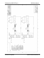
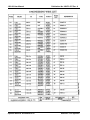
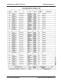
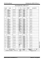
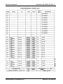
1
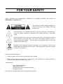
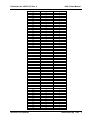
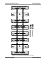
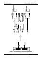
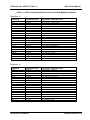
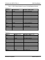
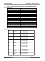
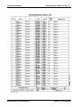
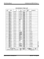
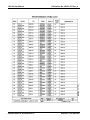
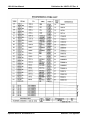
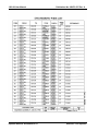
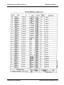
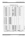
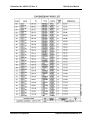
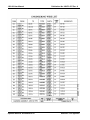
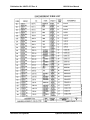
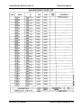
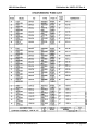
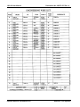
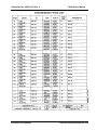
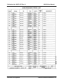
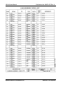
RACAL INSTRUMENTS™
1260-38
MULTIPLEXER/SCANNER
Publication No. 980673-037 Rev. A
Astronics Test Systems Inc.
4 Goodyear, Irvine, CA 92618
Tel: (800) 722-2528, (949) 859-8999; Fax: (949) 859-7139
[email protected] [email protected]
[email protected] http://www.astronicstestsystems.com
Copyright 1995 by Astronics Test Systems Inc. Printed in the United States of America. All
rights reserved. This book or parts thereof may not be reproduced in any form without written
permission of the publisher.
THANK YOU FOR PURCHASING THIS
ASTRONICS TEST SYSTEMS PRODUCT
For this product, or any other Astronics Test Systems product that incorporates software drivers,
you may access our web site to verify and/or download the latest driver versions. The web address
for driver downloads is:
http://www.astronicstestsystems.com/support/downloads
If you have any questions about software driver downloads or our privacy policy, please contact us
at:
[email protected]
WARRANTY STATEMENT
All Astronics Test Systems products are designed to exacting standards and manufactured in full
compliance to our AS9100 Quality Management System processes.
This warranty does not apply to defects resulting from any modification(s) of any product or part
without Astronics Test Systems express written consent, or misuse of any product or part. The
warranty also does not apply to fuses, software, non-rechargeable batteries, damage from battery
leakage, or problems arising from normal wear, such as mechanical relay life, or failure to follow
instructions.
This warranty is in lieu of all other warranties, expressed or implied, including any implied warranty
of merchantability or fitness for a particular use. The remedies provided herein are buyer’s sole
and exclusive remedies.
For the specific terms of your standard warranty, contact Customer Support. Please have the
following information available to facilitate service.
1. Product serial number
2. Product model number
3. Your company and contact information
You may contact Customer Support by:
E-Mail:
[email protected]
Telephone:
+1 800 722 3262
(USA)
Fax:
+1 949 859 7139
(USA)
RETURN OF PRODUCT
Authorization is required from Astronics Test Systems before you send us your product or sub-assembly for
service or calibration. Call or contact Customer Support at 1-800-722-3262 or 1-949-859-8999 or via fax at 1949-859-7139. We can also be reached at: [email protected].
If the original packing material is unavailable, ship the product or sub-assembly in an ESD shielding bag and
use appropriate packing materials to surround and protect the product.
PROPRIETARY NOTICE
This document and the technical data herein disclosed, are proprietary to Astronics Test Systems, and shall
not, without express written permission of Astronics Test Systems, be used in whole or in part to solicit
quotations from a competitive source or used for manufacture by anyone other than Astronics Test Systems.
The information herein has been developed at private expense, and may only be used for operation and
maintenance reference purposes or for purposes of engineering evaluation and incorporation into technical
specifications and other documents which specify procurement of products from Astronics Test Systems.
TRADEMARKS AND SERVICE MARKS
All trademarks and service marks used in this document are the property of their respective owners.
•
Racal Instruments, Talon Instruments, Trig-Tek, ActivATE, Adapt-A-Switch, N-GEN, and PAWS are
trademarks of Astronics Test Systems in the United States.
DISCLAIMER
Buyer acknowledges and agrees that it is responsible for the operation of the goods purchased and
should ensure that they are used properly and in accordance with this document and any other
instructions provided by Seller. Astronics Test Systems products are not specifically designed,
manufactured or intended to be used as parts, assemblies or components in planning, construction,
maintenance or operation of a nuclear facility, or in life support or safety critical applications in
which the failure of the Astronics Test Systems product could create a situation where personal
injury or death could occur. Should Buyer purchase Astronics Test Systems product for such
unintended application, Buyer shall indemnify and hold Astronics Test Systems, its officers,
employees, subsidiaries, affiliates and distributors harmless against all claims arising out of a claim
for personal injury or death associated with such unintended use.
FOR YOUR SAFETY
Before undertaking any troubleshooting, maintenance or exploratory procedure, read carefully the
WARNINGS and CAUTION notices.
This equipment contains voltage hazardous to
human life and safety, and is capable of inflicting
personal injury.
If this instrument is to be powered from the AC line (mains) through an autotransformer,
ensure the common connector is connected to the neutral (earth pole) of the power
supply.
Before operating the unit, ensure the conductor (green wire) is connected to the ground
(earth) conductor of the power outlet. Do not use a two-conductor extension cord or a
three-prong/two-prong adapter. This will defeat the protective feature of the third
conductor in the power cord.
Maintenance and calibration procedures sometimes call for operation of the unit with
power applied and protective covers removed. Read the procedures and heed warnings
to avoid “live” circuit points.
Before operating this instrument:
1. Ensure the proper fuse is in place for the power source to operate.
2. Ensure all other devices connected to or in proximity to this instrument are properly grounded or
connected to the protective third-wire earth ground.
If the instrument:
-
fails to operate satisfactorily
shows visible damage
has been stored under unfavorable conditions
has sustained stress
Do not operate until performance is checked by qualified personnel.
This page was left intentionally blank.
Publication No. 980673-037 Rev. A
1260-38 User Manual
NOTE FOR SYSTEMS WITH 1260-OPT 01T
The “Module-Specific Syntax” section of this manual shows the command syntax for the 1260-01S
Smart Card. If you are using the newer 1260-01T Smart Card, the commands will NOT work as
shown.
Consult the 1260-01T Manual for a description of the commands that may be used with the 126001T Smart Card.
The channel numbers described in this manual are valid for the 1260-01T. The channel numbers
continue to be used for the 1260-01T.
The syntax of the commands that use channel numbers has changed for those cards controlled by
the 1260-01T.
The new syntax used to close a channel is:
CLOSE (@ <module address> ( <channel> ) )
For example, with for a relay module whose <module address> is set to 7, closing <channel> 0 is
performed with the command:
CLOSE (@ 7 (0))
Using the older 1260-01S, the command would be (as shown in this manual):
CLOSE 7.0
Many other command syntax differences exist. Please consult chapter 2 of the 1260-01T manual
for a description of the commands which are available for the 1260-01T.
Astronics Test Systems
Addendum Page 6/98
1
1260-38 User Manual
Publication No. 980673-037 Rev. A
Control Information for the 1260-38A and 1260-38B
The following information describes the control-register-to-relay-channel mapping for a 1260-38A or 1260-38B
Relay Module. This information may be used to control the module when using a 1260-01T in the registerbased mode of operation.
Each channel on this module is controlled by setting or clearing a single bit. Control Registers on the module
operate 8 channels simultaneously. There are eight control bits per Control Register. Setting the bit to a 1
closes the relay; setting the bit to a 0 opens the relay.
The table below shows the mapping between logical channels used to operate the relay module in messagebased mode and the bits within the Control Registers that may be used to operate the channel in registerbased mode.
Each Control Register is located 2 addresses from the previous Control Register. This is shown in Table 2-2
of the 1260-01T manual. Control Register 0 is located at the “Base A24 Address” for the module. Consult the
“Register-Based Operation” Section of Chapter 2 of the 1260-01T manual for a description of calculating
control register addresses.
Note that when the 1260-01T message-based interface is used, ODD MUXes (channels 10 through 17, 30
through 37, channels 50 through 57, …, 150 through 157) are operated in parallel with EVEN MUXes to
operate as a 4-wire MUX. That is, when channel 0 is closed using the message-based interface with a 126038B, the firmware also closes channel 10; when channel 143 is opened, the firmware opens channel 153 as
well.
Channel
0
1
2
3
4
5
6
7
10*
11*
12*
13*
14*
15*
16*
17*
20
21
22
23
24
25
26
27
30*
31*
32*
33*
34*
35*
36*
37*
40
41
42
43
44
45
Addendum Page 6/98
2
Control Register
0
0
0
0
0
0
0
0
1
1
1
1
1
1
1
1
2
2
2
2
2
2
2
2
3
3
3
3
3
3
3
3
4
4
4
4
4
4
Control Bit
0
1
2
3
4
5
6
7
0
1
2
3
4
5
6
7
0
1
2
3
4
5
6
7
0
1
2
3
4
5
6
7
0
1
2
3
4
5
Astronics Test Systems
Publication No. 980673-037 Rev. A
Channel
46
47
50*
51*
52*
53*
54*
55*
56*
57*
60
61
62
63
64
65
66
67
70*
71*
72*
73*
74*
75*
76*
77*
80
81
82
83
84
85
86
87
90*
91*
92*
93*
94*
95*
96*
97*
100
101
102
103
104
105
106
107
110*
111*
112*
113*
114*
115*
116*
117*
120
121
122
123
124
125
Astronics Test Systems
1260-38 User Manual
Control Register
4
4
5
5
5
5
5
5
5
5
6
6
6
6
6
6
6
6
7
7
7
7
7
7
7
7
8
8
8
8
8
8
8
8
9
9
9
9
9
9
9
9
10
10
10
10
10
10
10
10
11
11
11
11
11
11
11
11
12
12
12
12
12
12
Control Bit
6
7
0
1
2
3
4
5
6
7
0
1
2
3
4
5
6
7
0
1
2
3
4
5
6
7
0
1
2
3
4
5
6
7
0
1
2
3
4
5
6
7
0
1
2
3
4
5
6
7
0
1
2
3
4
5
6
7
0
1
2
3
4
5
Addendum Page 6/98
3
1260-38 User Manual
Publication No. 980673-037 Rev. A
Channel
126
127
130*
131*
132*
133*
134*
135*
136*
137*
140
141
142
143
144
145
146
147
150*
151*
152*
153*
154*
155*
156*
157*
1000
1001**
1002**
2000
2001**
2002**
3000
3001**
3002**
4000
4001**
4002**
5000
5001**
5002**
6000
6001**
6002**
7000
7001**
7002**
8002**
9000
9001
9002
9003
9004
9005
9006
9007
Control Register
12
12
13
13
13
13
13
13
13
13
14
14
14
14
14
14
14
14
15
15
15
15
15
15
15
15
16
16
16
16
16
16
17
17
17
17
17
17
18
18
18
18
18
18
19
19
19
19
16
16
17
17
18
18
19
19
Control Bit
6
7
0
1
2
3
4
5
6
7
0
1
2
3
4
5
6
7
0
1
2
3
4
5
6
7
1
2
0
5
6
4
1
2
0
5
6
4
1
2
0
5
6
5
1
2
0
4
3
7
3
7
3
7
3
5
* This channel is operated automatically by the firmware for the 1260-38B when controlled using the messagebased interface. This channel is NOT programmable when using the message-based interface for the 126038B. This channel is set to the same state as the corresponding even MUX channel (e.g. when channel 127
is closed, channel 137 is closed automatically by the firmware; when channel 24 is opened, channel 34 is also
opened by the firmware).
** This channel is not available when programming a 1260-38B in message-based mode.
Addendum Page 6/98
4
Astronics Test Systems
Publication No. 980673-037 Rev. A
1260-38 User Manual
Table of Contents
Chapter 1 ............................................................................................................................ 1-1
MODULE SPECIFICATION .......................................................................................................... 1-1
Introduction ............................................................................................................................... 1-1
1260-38 Module Specification ................................................................................................... 1-2
Ordering Information ................................................................................................................. 1-5
Safety ........................................................................................................................................ 1-5
Chapter 2 ............................................................................................................................ 2-1
INSTALLATION INSTRUCTIONS ................................................................................................. 2-1
Unpacking and Inspection ......................................................................................................... 2-1
Option 01 Installation ................................................................................................................. 2-1
Module Installation..................................................................................................................... 2-2
1260-38 ID Byte ........................................................................................................................ 2-2
Astronics Test Systems
i
1260-38 User Manual
Publication No. 980673-037 Rev. A
Chapter 3 ............................................................................................................................ 3-1
MODULE OPERATION ................................................................................................................ 3-1
Module Configuration ................................................................................................................ 3-1
Two-Wire Operation .............................................................................................................. 3-2
Four-Wire Operation .............................................................................................................. 3-2
One-Wire Operation .............................................................................................................. 3-2
100Ω Resistor Channels ........................................................................................................ 3-3
Front Panel Connectors ......................................................................................................... 3-3
Mating Connectors................................................................................................................. 3-3
1260-38 Module Specific Syntax ............................................................................................... 3-4
Syntax ................................................................................................................................... 3-4
CLOSE Command ............................................................................................................. 3-5
OPEN Command ............................................................................................................... 3-5
PDATAOUT Command ...................................................................................................... 3-5
PSETUP Command ........................................................................................................... 3-6
Chapter 4 ............................................................................................................................ 4-1
OPTIONAL HARNESS ASSEMBLIES .......................................................................................... 4-1
ii
Astronics Test Systems
Publication No. 980673-037 Rev. A
1260-38 User Manual
List of Figures
Figure 1-1, 1260-38 Multiplexer / Scanner .................................................................................... 1-2
Figure 3-1, 1260-38 Module Configuration Block Diagram ............................................................ 3-7
Figure 3-2, 1260-38 Multiplexer Configuration Block Diagram ...................................................... 3-8
Figure 3-3, 1260-38 Pin Connections, Front View ......................................................................... 3-9
Astronics Test Systems
iii
1260-38 User Manual
Publication No. 980673-037 Rev. A
List of Tables
Table 3-1, 1260-38 Channel Number/Connector Pin/Cable Mapping.......................................... 3-10
iv
Astronics Test Systems
Publication No. 980673-037 Rev. A
1260-38 User Manual
DOCUMENT CHANGE HISTORY
Revision
A
Astronics Test Systems
Date
Description of Change
11/11/09
Revised per EO 29960
Revised format to current standards. Company
name revised throughout manual. Manual now
revision letter controlled.
Added Document
Change History Page v. Back of cover sheet.
Revised Warranty Statement, Return of Product,
Proprietary Notice and Disclaimer to current
standards. (Chap2-1) Unpacking and inspection.
Revise
to
current
standards.
Removed
Reshipment Instructions in (Chap. 2-1) and
removed (Chap 5). Information. Now appears in
first 2 sheets behind cover sheet. Updated table
of contents to reflect changes made. .
Added company name to footer/lower corner
opposite of Page no’s i thru vi.
v
1260-38 User Manual
Publication No. 980673-037 Rev. A
This page was left intentionally blank.
vi
Astronics Test Systems
Publication No. 980673-037 Rev. A
1260-38 User Manual
Chapter 1
MODULE SPECIFICATION
Introduction
The 1260-38 1 x 128 Two-Wire Scanner/Multiplexer Module
consists of eight pairs of 1 x 8 multiplexers. These eight pairs of
multiplexers, in conjunction with interconnecting relays, allow the
1260-38 module to be configured as:
•
One 1 x 64 Four-wire multiplexer
•
One 1 x 128 Two-wire multiplexer
•
One 1 x 256 One-wire multiplexer
In addition, each pair of 1 x 8 multiplexers can be independently
configured as:
•
Two 1 x 8 Two-wire multiplexers
•
One 1 x 16 Two-wire multiplexer
•
One 1 x 32 One-wire multiplexer
•
One 1 x 8 Four-wire multiplexer
Figure 3-1, 1260-38 Module Configuration Block Diagram, and
Figure 3-2, 1260-38 Multiplexer Configuration Block Diagram,
shows a diagrammatic representation of the switch module and
multiplexer pair, respectively.
Astronics Test Systems
Module Specification 1-1
1260-38 User Manual
Publication No. 980673-037 Rev. A
Figure 1-1, 1260-38 Multiplexer / Scanner
1260-38 Module
Specification
Maximum Switch Power
125VA, 60W
Maximum Switch Voltage
25OVAC, 22OVDC
Maximum Switch Current
2A AC, 2A DC
Bandwidth (50Ω)
1 x 8 Configuration
1 x 16 Configuration
1 x 128 Configuration
>30MHz
>30MHz
>2MHz
Insertion Loss (50Ω)
1 x 8 Configuration
Module Specification 1-2
<0.10dB to 100kHz
<0.25dB to 1MHz
<1.70dB to 10MHz
Astronics Test Systems
Publication No. 980673-037 Rev. A
1260-38 User Manual
Insertion Loss (50Ω)
1 x 128 Configuration
< 0.20dB to 100kHz
< 1.00dB to 1MHz
Crosstalk (50Ω)
1 x 8 Configuration
< -55dB to 100kHz
< -50dB to I MHz
< -22dB at 10MHz
Isolation (50Ω)
1 x 8 Configuration
> 40dB to 100kHz
> 35dB to 1MHz
> 20dB at 10MHZ
Path Resistance
1 x 8 Configuration
1 x 128 Configuration
< 0.25Ω
< 0.75Ω
Thermal EMF
1 x 8 Configuration
1 x 128 Configuration
< 15µV
< 20µV
Impedance
High-Low
High-Chassis
Low to Chassis
> 2000MΩ
> 2000MΩ
> 2000MΩ
Capacitance
Channel to Chassis (1 x 8)
Channel to Chassis (1 x 128)
High to Low (1 x 8)
High to Low (1 x 128)
< 5pF
< 5pF
< 120pF
< 600pF
Temperature
Operating
Non-Operating
Relative Humidity
Astronics Test Systems
00C to +550C
400C to +710C
95+1-5% RH NonCondensing < 300C
75+1-5 %RH > 300C
45+1-5 %RH > 400C
Module Specification 1-3
1260-38 User Manual
Publication No. 980673-037 Rev. A
Altitude
Operating
Non-Operating
Vibration
10,000ft
15,000ft
0.013" double amplitude,
5-55Hz
Shock, functional
30g, 11msec, ½ sine wave
Bench Handling
4inch drop
Cooling Requirement
Without Option 01 installed
Airflow
Backpressure
With Option 01 installed
Airflow
Backpressure
Power Requirement
Without Option 01 installed
+5V Static Current, I pm
+5V Dynamic Current, I dm
With Option 01 installed
+5V Static Current, I pm
+5V Dynamic Current, I dm
+24V Static Current, I pm
+24V Dynamic Current, I dm
1.0 liters/sec
0.05mm H20
2.0 liters/sec
0.2mm H20
0.4A
0.075A
2.5A
0.225A
6mA per energized relay
0A
Weight
Without Option 01 installed
With Option 01 installed
3.21b (1.45kg)
3.51b (1.60kg)
Minimum Option 01 Firmware Revision
Module Specification 1-4
28.1
Astronics Test Systems
Publication No. 980673-037 Rev. A
Ordering
Information
1260-38 User Manual
Listed below are part numbers for both the 1260-38 Switch Module
and available mating connector.
Model Numbers
Description
Part #
1260-38 Switch Module
1260-38, 2w, 1 x 128 sc mux, 2 amp
407410
160-Pin Mating Connector
160-Pin Connector Kit with backshell and pins
407407
Cable Assy, 6ft, sleeved
160-Pin Cable Assy, 6ft, 24GA
407408
Cable Assy, 12ft, sleeved
160-Pin Cable Assy, 12ft, 24GA
407409
Safety
Astronics Test Systems
Refer to the "FOR YOUR SAFETY" page preceding the Table of
Contents. Follow all NOTES, CAUTIONS and WARNINGS to
ensure personal safety and prevent damage to the instrument.
Module Specification 1-5
1260-38 User Manual
Publication No. 980673-037 Rev. A
This page was left intentionally blank.
Module Specification 1-6
Astronics Test Systems
Publication No. 980673-037 Rev. A
1260-38 User Manual
Chapter 2
INSTALLATION INSTRUCTIONS
Unpacking and
Inspection
1. Remove the 1260-38 module and inspect it for damage. If any
damage is apparent, inform the carrier immediately. Retain
shipping carton and packing material for the carrier’s
inspection.
2. Verify that the pieces in the package you received contain the
correct 1260-38 module option and the 1260-38 Users Manual.
Notify Customer Support if the module appears damaged in
any way. Do not attempt to install a damaged module into a
VXI chassis.
3. The 1260-38 module is shipped in an anti-static bag to prevent
electrostatic damage to the module. Do not remove the module
from the anti-static bag unless it is in a static-controlled area
Option 01
Installation
Astronics Test Systems
Installation of the Option 01 to the 1260-38 is described in the
Installation Section of the 1260 Series VXI Switching Cards
Manual.
Installation Instructions 2-1
1260-38 User Manual
Publication No.980673-037 Rev. A
Module
Installation
Installation of the 1260-38 Switching Module into a VXI mainframe,
including the setting of switches SW1-1 through SW1-4, 5W2 and
5W3, is described in the Installation section of the 1260 Series VXI
Switching Cards Manual. Configuration of switches SW 1-5 and
SW 1-6 is described below.
1260-38 ID Byte
Refer to Section 2 of the Series 1260 VXI Switching Card Manual
for an explanation of Module ID Byte.
The 1260-38 may be configured for two-wire or four wire switching.
The two-wire configuration closes one relay for the selected
channel. Four-wire configuration closes two relays for the selected
channel. Each configuration responds to different sets of values
for <channel number>. The set of values the 1260-38 responds to
is controlled by switch SW1- 5.
The switch settings that
correspond to the two configurations are as follows:
*
Configuration
S1 Switch 5
S1 Switch 6
Four-wire
Off
Off
Two-wire
On
Off
The 1260-38 is set at the factory for two-wire configuration.
NOTE:
*The software will report the Model Number as “126038A” for the two-wire configuration, or “1260-38B” for
the four-wire configuration.
Installation Instructions 2-2
Astronics Test Systems
Publication No. 980673-037 Rev. A
1260-38 User Manual
Chapter 3
MODULE OPERATION
Module
Configuration
The 1260-38 is a 1 x 128 Two-Wire Scanner/Multiplexer Module
consisting of eight pairs of 1 x 8 multiplexers. These eight pairs of
multiplexers, in conjunction with interconnecting relays, allow the
1260-38 module to be configured as:
•
•
•
One 1 x 64 Four-wire multiplexer
One 1 x 128 Two-wire multiplexer
One 1 x 256 One-wire multiplexer
Each pair of 1 x 8 multiplexers can he independently configured
as:
•
•
•
•
Two 1 x 8 Two-wire multiplexers
One 1 x 16 Two-wire multiplexer
One 1 x 32 One-wire multiplexer
One 1 x 8 Four-wire multiplexer
Reference should be made to Figure 3-1, 1260-38 Module
Configuration Block Diagram, and Figure 3-2, 1260-38 multiplexer
Configuration Block Diagram.
The multiplexer pairs consist of two 1 x 8 multiplexers, giving a
total of sixteen 1 x 8 multiplexers (00 through 15). Each 1 x 8
multiplexer consists of one two-wire common and eight two-wire
channels. The channels are numbered 0000 to 0007 for
multiplexer 00, through 0150 to 0157 for multiplexer 15.
The even-numbered multiplexers (00,02,... 14) have a second twowire common which has 100Ω series resistors in both the high and
low paths. The even-numbered multiplexers also include a onewire relay (channels 9000 though 9007) which select the high or
low path of both two-wire common and 100Ω resistor two-wire
common.
Interconnecting relays (channels 1002, 2002, ....8002) join the
multiplexers to form multiplexer pairs. The multiplexer pairs are
formed by multiplexers 00-01, 02-03, 04-05, 06-07, 08-09, 10-11,
12-13, and 14-15.
The multiplexer pairs are joined to each other through two more
pairs of interconnecting relays (1000, 1001,2000, 2001, …7000,
Astronics Test Systems
Module Operation 3-1
1260-38 User Manual
Publication No. 980673-037 Rev. A
7001). This allows pairs of the module to be configured for fourwire operation.
Two-Wire
Operation
Two-wire configuration gives the most flexibility as it allows all
channels (0000 through 0157, 1000 through 8000, and 9000
through 9007) to be selected.
Interconnecting relays (1000, 1001, 2000, 2001, …..7000, 7001)
permit linking of all the 1 x 8 multiplexers to give configurations
from sixteen 1 x 8 multiplexers up to one 1 x 128 multiplexer.
Example: Make a two-wire 1 x 32 using multiplexes 00,01,02,03
Close channels 1000, 1002 and 2002.
Four-Wire
Operation
Four-wire configuration permits four-wire closures only. Only
even-numbered multiplexers (00, 02, ….14) may be selected.
Closing a channel in an even-numbered multiplexer also closes
the equivalent channel in the adjacent odd-numbered multiplexer.
For example, closing Channel 0002 (channel 2 of multiplexer 00)
will also close channel 0012 (channel 2 of multiplexer 01).
The same applies to the interconnect relays (channels 1000, 1001,
2000, 2001, …..7000, 7001). Closing channel 1000 will also close
channel 1001). In four-wire operation, the interconnect relays
permit configurations of eight 1 x 8 multiplexers up to one 1 x 64
multiplexer.
Example: Make a four-wire 1 x 24 using multiplexers 00, 01, 02,
03, 04, 05
Close channels 1000 and 2000.
One-Wire
Operation
One-wire switching must be performed with the 1260-38
configured for two-wire operation. Each even-numbered
multiplexer includes a one-wire relay (channels 9000, 9001,
9007). This allows configurations from sixteen 1 x 16 multiplexers
up to one 1 x 256 multiplexer.
Example: Make a one-wire 1 x 96 using multiplexers 00, 01, 02,
03, 04, 05
Close channels 1000, 1002, 2000, 2002 and 3002.
When the one-wire channel is open, the one-wire common is
connected to the two-wire high path. When the one-wire channel
is closed, the one-wire common is connected to the two-wire low
Module Operation 3-2
Astronics Test Systems
Publication No. 980673-037 Rev. A
1260-38 User Manual
path. The same applies to the one-wire common with 1000 series
resistor.
100Ω Resistor
Channels
Even-numbered multiplexers have two-wire commons that include
100Ω series resistors in both the high and low paths. This may be
useful for applications where transient suppression is of concern.
The resistors are rated at 1/8W. The one-wire relay is also
connected to the two-wire resistor common to provide a one-wire
resistor path.
Front Panel
Connectors
The 1260-38 front panel connectors are labeled J200 and J201.
The connector type is 5 x 32 (160-pin) DIN 41 612 male. The pin
numbering is shown in Figure 3-3.
The mapping of channel numbers to connector pins and the
available mating connector cable is given in Table 3-1.
Mating
Connectors
There are no mating connectors shipped with the 1260-38 module.
Astronics Test Systems offers the following accessories for mating
connectors (see ordering information for part numbers):
•
160-Pin Connector Kit with backshell and pins
•
160-Pin Cable Assy, 6ft, 240A
•
160-Pin Cable Assy, l2ft, 24GA
The 160-Pin Connector kit consists of a connector housing,
customized backshell and 170 crimp pins. The backshell design
has been optimized for system integration. The connector kit has
been designed for 22 to 26 gauge cable. The crimp pin will lock or
'click' into the connector housing only when installed correctly.
The assembler should ensure that the crimp pin is locked by
tugging on the cable after insertion.
The hand crimp tool for loose crimp contacts is Erni Part Number
014 374. The disassembly tool is Erni Part Number 471 555.
The cable assemblies (optional lengths of 6ft. or 12ft.) use the
160-Pin Connector kit along with two 80-wire multi-colored 24
gauge cables. One end is un-terminated. Refer to Table 3-1 for
the mapping of channels to connector and cable.
Astronics Test Systems
Module Operation 3-3
1260-38 User Manual
Publication No. 980673-037 Rev. A
1260-38 Module
Specific Syntax
The Module Specific Syntax for the 1260-38 is required in the use
of the OPEN and CLOSE commands. It will also appear in data
output by the Master in response to the PDATAOUT and PSETUP
commands.
Syntax
The Module Specific Syntax for the 1260-38 Multiplexer/Scanner
module is as follows:
<COMMAND> relay designator> [;<relay designator>]
where:
<relay designator> ::= <module address>.<channel range>
[,<channel range>...]
<channel range> ::= <channel descriptor>[-<channel descriptor>]
<channel descriptor> ::= <interconnect><mux select><channel>
<module address> ::= 1.. 12
<interconnect> ::= 0 to 9
Where:
0 = multiplexer channels.
1 to 8 = multiplexer interconnect relays.
9 = one-wire high/low select.
<mux select> ::= 00 to 15
For two-wire mode: selects one of 16 1 x 8 multiplexers.
For four-wire mode: selects two of 16 1 x 8 multiplexers. Only
even number multiplexers are allowed. Selecting multiplexer 00
will also select same channel on next multiplexer in sequence, in
this case multiplexer 01.
<channel> ::= 0 to 7
0 to 7 for multiplexers
0 to 2 for interconnect relays
0 to 7 for one-wire relays
Module Operation 3-4
Astronics Test Systems
Publication No. 980673-037 Rev. A
1260-38 User Manual
NOTE:
The <module address> used here is not the VXIbus
defined logical address of the 1260 Series Master. It
is unique to the 1260 Series and describes the
switching module in relation to the Master. This
address corresponds to the binary value of the switch
setting of SW1 on the switching module PCB. Refer
to the Installation Section of the 1260 Series VXI
Switching Cards Manual for more information.
CLOSE Command
The CLOSE command is used to close a channel.
Example:
CL[OSE] 1.0012
This CLOSE command will close channel 2 of multiplexer 0 1 on
the module at switch card module address 1.
OPEN Command
The OPEN command is used to open a channel.
Example:
OP[EN] 3.0107
This OPEN command will open channel 7 of multiplexer 10 on the
module at switch card module address 3.
Note that channels remain closed until opened by an OPEN
command, RESET command, VXI hard or soft reset, or power-off.
PDATAOUT
Command
The PDATAOUT command causes the specified module to
transmit the CLOSED state of the relays within the switch module
to the 1260 Controller. The syntax used is:
PD[ATAOUT] <module address> [;<module address>] [;<module address>]
The responses to the PDATAOUT command is as follows:
1260-38:
Two-wire
<module address>. 1260-38A 1x128 2-WIRE SCANNER/MULTIPLEXER
<module address> . <channel range>[,<channel range>] [,<channel range>]
<module address>.END
Astronics Test Systems
Module Operation 3-5
1260-38 User Manual
Publication No. 980673-037 Rev. A
1260-38 Four-Wire
<module address>. 1260-38B 1x64 4-WIRE SCANNER/MULTIPLEXER
<module address> . <channel range>[,<channel range>] [,<channel range>]
<module address>.END
The response to the PDATAOUT command consists of a header
on the first line as with the PSETUP response. The next line
details the channels currently closed on the module and is blank
when no channels are closed. Again, the last line is denoted by
the 11END'1 string of characters.
PSETUP Command
The PSETUP command causes the specified module setup to be
transmitted to the VXI Controller. The syntax used is:
PS[ETUP] <module address>[ ;<module address>] [;<module address>]
Where:
<module address> is the switch card address.
The responses to the PSETUP command for the 1260-38
Multiplexer/Scanner is as follows:
1260-38:
Two-wire
<module address>. 1260-38A 1x128 2-WIRE SCANNER/MULTIPLEXER
<module address> . BBM
<module address>.END
1260-38
Four-Wire
<module address>. 1260-38B 1x64 4-WIRE SCANNER/MULTIPLEXER
<module address>. BBM
<module address>.END
The response to the PSETUP command consists of a header on
the first line. The header describes the model number following an
A or B designating two or four-wire, respectively. The next line
designates the setup mode for scanning which, by default, is
Break-Before-Make (BBM). The last line containing the "END"
characters denotes no more information to report.
Module Operation 3-6
Astronics Test Systems
Publication No. 980673-037 Rev. A
1260-38 User Manual
Figure 3-1, 1260-38 Module Configuration Block Diagram
Astronics Test Systems
Module Operation 3-7
1260-38 User Manual
Publication No. 980673-037 Rev. A
Figure 3-2, 1260-38 Multiplexer Configuration Block Diagram
Module Operation 3-8
Astronics Test Systems
Publication No. 980673-037 Rev. A
1260-38 User Manual
R acal
In s tr u m e n ts
!
a b c
d
J
2
0
0
126 0-38
FA IL
J
2
0
1
e
32
31
30
29
28
27
26
25
24
23
22
21
20
19
18
17
16
15
14
13
12
11
10
9
8
7
6
5
4
3
2
1
!
Figure 3-3, 1260-38 Pin Connections, Front View
Astronics Test Systems
Module Operation 3-9
1260-38 User Manual
Publication No. 980673-037 Rev. A
Table 3-1, 1260-38 Channel Number/Connector Pin/Cable Mapping
Multiplexer 00
Channel #
Connector Pin #
Connector I Cable # I Color
0000 Hi
0000 Lo
0001 Hi
0001 Lo
0002 Hi
0002 Lo
0003 Hi
0003 Lo
0004 Hi
0004 Lo
0005 Hi
0005 Lo
0006 Hi
0006 Lo
0007 Hi
0007 Lo
COM00 Hi
COM00 Lo
COM00R Hi
COM00R Lo
COM001W
COM00lWR
J200P31A
J200P32A
J200P31B
J200P32B
J200P31D
J200P32D
J200P31E
J200P32E
J200P29A
J200P30A
J200P29B
J200P30B
J200P29D
J200P30D
J200P29E
J200P30E
J200P31C
J200P32C
J200P27C
J200P28C
J200P30C
J200P29C
P200, CABLE 1, white/black/orange/violet
P200, CABLE 1, white/black/yellow/grey
P200, CABLE 1, white/black/orange/grey
P200, CABLE 1, white/black/green/blue
P200, CABLE 1, white/black/yellow/blue
P200, CABLE 1, white/black/green/grey
P200, CABLE 1, white/black/yellow/violet
P200, CABLE 1, white/black/blue/violet
P200, CABLE 1, white/black/brown/violet
P200, CABLE 1, white/black/red/violet
P200, CABLE 1, white/black/brown/grey
P200, CABLE 1, white/black/red/grey
P200, CABLE 1, white/black/red/green
P200, CABLE 1, white/black/orange/green
P200, CABLE 1, white/black/red/blue
P200, CABLE 1, white/black/orange/blue
P200, CABLE 1, white/black/yellow/green
P200, CABLE 1, white/black/green/violet
P200, CABLE 1, white/blue/violet
P200, CABLE 1, white/black/brown/yellow
P200, CABLE 1, white/black/orange/yellow
P200, CABLE 1, white/black/red/yellow
Multiplexer 01
Channel #
Connector Pin #
Connector / Cable # I Color
0010 Hi
J200P27A
P200, CABLE 1, white/green/violet
0010 Lo
J200P28A
P200, CABLE 1, white/black/brown/red
0011 Hi
J200P27B
P200, CABLE 1, white/green/grey
0011 Lo
J200P28B
P200, CABLE 1, white/black/brown/orange
0012 Hi
J200P27D
P200, CABLE 1, white/blue/grey
0012 Lo
J200P28D
P200, CABLE 1, white/black/brown/green
0013 Hi
J200P27E
P200, CABLE 1, white/violet/grey
0013 Lo
J200P28E
P200, CABLE 1, white/black/brown/blue
0014 Hi
J200P25A
P200, CABLE 1, white/orange/yellow
0014 Lo
J200P26A
P200, CABLE 1, white/yellow/green
0015 Hi
J200P25B
P200, CABLE 1, white/orange/green
0015 Lo
J200P26B
P200, CABLE 1, white/yellow/blue
0016 Hi
J200P25D
P200, CABLE 1, white/orange/violet
0016 Lo
J200P26D
P200, CABLE 1, white/yellow/grey
0017 Hi
J200P25E
P200, CABLE 1, white/orange/grey
0017 Lo
J200P26E
P200. CABLE 1, white/green/blue
COM01 Hi
J200P25C
P200, CABLE 1, white/orange/blue
COM01 Lo
J200P26C
P200, CABLE 1, white/yellow/violet
Module Operation 3-10
Astronics Test Systems
Publication No. 980673-037 Rev. A
1260-38 User Manual
Table 3-1, 1260-38 Channel Number/Connector Pin/Cable Mapping Continued
Multiplexer 02
Channel #
Connector Pin #
Connector / Cable # / Color
0020 Hi
0020 Lo
0021 Hi
0021 Lo
0022 Hi
0022 Lo
0023 Hi
0023 Lo
0024 Hi
0024 Lo
0025 Hi
0025 Lo
0026 Hi
0026 Lo
0027 Hi
0027 Lo
COM02 Hi
COM02 Lo
COM02R Hi
COM02R Lo
COM021W
COM021WR
J200P23A
J200P24A
J200P23B
J200P24B
J200P23D
J200P24D
J200P23E
J200P24E
J200P21A
J200P22A
J200P21B
J200P22B
J200P21D
J200P22D
J200P21E
J200P22E
J200P23C
J200P24C
J200P19C
J200P20C
J200P22C
J200P21C
P200, CABLE 1, white/brown/green
P200, CABLE 1, white/red/yellow
P200, CABLE 1, white/brown/blue
P200, CABLE 1, white/red/green
P200, CABLE 1, white/brown/grey
P200, CABLE 1, white/red/violet
P200, CABLE 1, white/red/orange
P200, CABLE 1, white/red/grey
P200, CABLE 1, white/black/red
P200, CABLE 1, white/black/violet
P200, CABLE 1, white/black/orange
P200, CABLE 1, white/black/grey
P200, CABLE 1, white/black/green
P200, CABLE 1, white/brown/orange
P200, CABLE 1, white/black/blue
P200, CABLE 1, white/brown/yellow
P200, CABLE 1, white/brown/violet
P200, CABLE 1, white/red/blue
P200, CABLE 1, white/red
P200, CABLE 1, white/violet
P200, CABLE 1, white/brown/red
P200, CABLE 1, white/black/yellow
Multiplexer 03
Channel #
Connector Pin #
Connector / Cable # I Color
0030 Hi
0030 Lo
0031 Hi
0031 Lo
0032 Hi
0032 Lo
0033 Hi
0033 Lo
0034 Hi
0034 Lo
0035 Hi
0035 Lo
0036 Hi
0036 Lo
0037 Hi
0037 Lo
COM03 Hi
COM03 Lo
J200P19A
J200P20A
J200P19B
J200P20B
J200P19D
J200P20D
J200P19E
J200P20E
J200P17A
J200P18A
J200P17B
J200Pl8B
J200P17D
J200Pl8D
J200P17E
J200P18E
J200P17C
J200P18C
P200, CABLE 1, white/black
P200, CABLE 1, white/green
P200, CABLE 1, white/brown
P200, CABLE 1, white/blue
P200, CABLE 1, white/orange
P200, CABLE 1, white/grey
P200, CABLE 1, white/yellow
P200, CABLE 1, white/black/brown
P200, CABLE 1, black
P200, CABLE 1, green
P200, CABLE 1, brown
P200, CABLE 1, blue
P200, CABLE 1, orange
P200, CABLE 1, grey
P200, CABLE 1, yellow
P200. CABLE 1, white
P200, CABLE 1, red
P200, CABLE 1, violet
Astronics Test Systems
Module Operation 3-11
1260-38 User Manual
Publication No. 980673-037 Rev. A
Table 3-1, 1260-38 Channel Number/Connector Pin/Cable Mapping Continued
Multiplexer 04
Channel #
Connector Pin #
Connector / Cable # / Color
0040 Hi
0040 Lo
0041 Hi
0041 Lo
0042 Hi
0042 Lo
0043 Hi
0043 Lo
0044 Hi
0044 Lo
0045 Hi
0045 Lo
0046 Hi
0046 Lo
0047 Hi
0047 Lo
COM04 Hi
COM04 Lo
COM04R Hi
COM04R Lo
COM041W
COM041WR
J200P15A
J200P16A
J200P15B
J200P16B
J200P15D
J200P16D
J200P15E
J200P16E
J200P13A
J200P14A
J200P13B
J200Pl4B
J200P13D
J200P14D
J200P13E
J200Pl4E
J200P15C
J200P16C
J200P11C
J200P12C
J200P14C
J200P13C
P200, CABLE 2, white/black/orange/violet
P200, CABLE 2, white/black/yellow/grey
P200, CABLE 2, white/black/orange/grey
P200, CABLE 2, white/black/green/blue
P200, CABLE 2, white/black/yellow/blue
P200, CABLE 2, white/black/green/grey
P200, CABLE 2, white/black/yellow/violet
P200. CABLE 2. white/black/blue/violet
P200, CABLE 2, white/black/brown/violet
P200, CABLE 2, white/black/red/violet
P200, CABLE 2, white/black/brown/grey
P200, CABLE 2, white/black/red/grey
P200, CABLE 2, white/black/red/green
P200, CABLE 2, white/black/orangelgreen
P200, CABLE 2, white/black/red/blue
P200, CABLE 2, white/black/orange/blue
P200, CABLE 2, white/black/yellow/green
P200, CABLE 2, white/black/green/violet
P200, CABLE 2, white/blue/violet
P200, CABLE 2, white/black/brown/yellow
P200, CABLE 2, white/black/orange/yellow
P200, CABLE 2, white/black/red/yellow
Channel #
Connector Pin #
Connector / Cable # / Color
0050 Hi
0050 Lo
0051 Hi
0051 Lo
0052 Hi
0052 Lo
0053 Hi
0053 Lo
0054 Hi
0054 Lo
0055 Hi
0055 Lo
0056 Hi
0056 Lo
0057 Hi
0057 Lo
COM05 Hi
COM05 Lo
J200P11A
J200P12A
J200P11B
J200P12B
J200P11D
J200P12D
J200P11E
J200P12E
J200P9A
J200P10A
J200P9B
J200P10B
J200P9D
J200P10D
J200P9E
J200P10E
J200P9C
J200P10C
P200, CABLE 2, white/green/violet
P200, CABLE 2, white/black/brown/red
P200, CABLE 2, white/green/grey
P200, CABLE 2, white/black/brown/orange
P200, CABLE 2, white/blue/grey
P200, CABLE 2, white/black/brown/green
P200, CABLE 2, white/violet/grey
P200, CABLE 2, white/black/brown/blue
P200, CABLE 2, white/orange/yellow
P200, CABLE 2, white/yellow/green
P200, CABLE 2, white/orange/green
P200, CABLE 2, white/yellow/blue
P200, CABLE 2, white/orange/violet
P200, CABLE 2, white/yellow/grey
P200, CABLE 2, white/orange/grey
P200, CABLE 2, white/green/blue
P200, CABLE 2, white/orange/blue
P200, CABLE 2, white/yellow/violet
Multiplexer 05
Module Operation 3-12
Astronics Test Systems
Publication No. 980673-037 Rev. A
1260-38 User Manual
Table 3-1, 1260-38 Channel Number/Connector Pin/Cable Mapping Continued
Multiplexer 06
Channel #
Connector Pin #
Connector / Cable # / Color
0060 Hi
0060 Lo
0061 Hi
0061 Lo
0062 Hi
0062 Lo
0063 Hi
0063 Lo
0064 Hi
0064 Lo
0065 Hi
0065 Lo
0066 Hi
0066 Lo
0067 Hi
0067 Lo
COM06 Hi
COM06 Lo
COM06R Hi
COM06R Lo
COM061W
COM061WR
J200P7A
J200P8A
J200P7B
J200P8B
J200P7D
J200P8D
J200P7E
J200P8E
J200P5A
J200P6A
J200P5B
J200P6B
J200P5D
J200P6D
J200P5E
J200P6E
J200P7C
J200P8C
J200P3C
J200P4C
J200P6C
J200P5C
P200, CABLE 2, white/brown/green
P200, CABLE 2, white/red/yellow
P200, CABLE 2, white/brown/blue
P200, CABLE 2, white/red/green
P200, CABLE 2, white/brown/grey
P200, CABLE 2, white/red/violet
P200, CABLE 2, white/red/orange
P200, CABLE 2. white/red/grey
P200, CABLE 2, white/black/red
P200, CABLE 2, white/black/violet
P200, CABLE 2, white/black/orange
P200, CABLE 2, white/black/grey
P200, CABLE 2, white/black/green
P200, CABLE 2, white/brown/orange
P200, CABLE 2, white/black/blue
P200, CABLE 2, white/brown/yellow
P200, CABLE 2, white/brown/violet
P200, CABLE 2, white/red/blue
P200, CABLE 2, white/red
P200, CABLE 2, white/violet
P200, CABLE 2, white/brown/red
P200, CABLE 2, white/black/yellow
Multiplexer 07
Channel #
Connector Pin #
Connector / Cable # I Color
0070 Hi
0070 Lo
0071 Hi
0071 Lo
0072 Hi
0072 Lo
0073 Hi
0073 Lo
0074 Hi
0074 Lo
0075 Hi
0075 Lo
0076 Hi
0076 Lo
0077 Hi
0077 Lo
COM07 Hi
COM07 Lo
J200P3A
J200P4A
J200P3B
J200P4B
J200P3D
J200P4D
J200P3E
J200P4E
J200P1A
J200P2A
J200P1B
J200P2B
J200P1D
J200P2D
J200P1E
J200P2E
J200P1C
J200P2C
P200, CABLE 2, white/black
P200, CABLE 2, white/green
P200, CABLE 2, white/brown
P200, CABLE 2, white/blue
P200, CABLE 2, white/orange
P200, CABLE 2, white/grey
P200, CABLE 2, white/yellow
P200, CABLE 2, white/black/brown
P200, CABLE 2, black
P200, CABLE 2, green
P200, CABLE 2, brown
P200, CABLE 2, blue
P200, CABLE 2, orange
P200, CABLE 2, grey
P200, CABLE 2, yellow
P200, CABLE 2, white
P200, CABLE 2, red
P200, CABLE 2, violet
Astronics Test Systems
Module Operation 3-13
1260-38 User Manual
Publication No. 980673-037 Rev. A
Table 3-1, 1260-38 Channel Number/Connector Pin/Cable Mapping Continued
Multiplexer 08
Channel #
Connector Pin #
Connector / Cable # / Color
0080 Hi
0080 Lo
0081 Hi
0081 Lo
0082 Hi
0082 Lo
0083 Hi
0083 Lo
0084 Hi
0084 Lo
0085 Hi
0085 Lo
0086 Hi
0086 Lo
0087 Hi
0087 Lo
COM08 Hi
COM08 Lo
COM08R Hi
COM08R Lo
COM081W
COM081WR
J201P31A
J201P32A
J201P31B
J201P32B
J201P31D
J201P32D
J201P31E
J201P32E
J201P29A
J201P30A
J201P29B
J201P30B
J201P29D
J201P30D
J201P29E
J201P30E
J201P31C
J201P32C
J201P27C
J201P28C
J201P30C
J201P29C
P201, CABLE 1, white/black/orange/violet
P201, CABLE 1, white/black/yellow/grey
P201, CABLE 1, white/black/orange/grey
P201, CABLE 1, white/black/green/blue
P201, CABLE 1, white/black/yellow/blue
P201, CABLE 1, white/black/green/grey
P201, CABLE 1, white/black/yellow/violet
P201, CABLE 1, white/black/blue/violet
P201, CABLE 1, white/black/brown/violet
P201, CABLE 1, white/black/red/violet
P201, CABLE 1, white/black/brown/grey
P201, CABLE 1, white/black/red/grey
P201, CABLE 1, white/black/red/green
P201, CABLE 1, white/black/orange/green
P201, CABLE 1, white/black/red/blue
P201, CABLE 1, white/black/orange/blue
P201, CABLE 1, white/black/yellow/green
P201, CABLE 1, white/black/green/violet
P201, CABLE 1, white/blue/violet
P201, CABLE 1, white/black/brown/yellow
P201, CABLE 1, white/black/orange/yellow
P201, CABLE 1, white/black/red/yellow
Channel #
Connector Pin #
Connector / Cable # I Color
0090 Hi
0090 Lo
0091 Hi
0091 Lo
0092 Hi
0092 Lo
0093 Hi
0093 Lo
0094 Hi
0094 Lo
0095 Hi
0095 Lo
0096 Hi
0096 Lo
0097 Hi
0097 Lo
COM09 Hi
COM09 Lo
J201P27A
J201P28A
J201P27B
J201P28B
J201P27D
J201P28D
J201P27E
J201P28E
J201P25A
J201P26A
J201P25B
J201P26B
J201P25D
J201P26D
J201P25E
J201P26E
J201P25C
J201P26C
P201, CABLE 1, white/green/violet
P201, CABLE 1, white/black/brown/red
P201, CABLE 1, white/green/grey
P201, CABLE 1, white/black/brown/orange
P201, CABLE 1, white/blue/grey
P201, CABLE 1, white/black/brown/green
P201, CABLE 1, white/violet/grey
P201, CABLE 1, white/black/brown/blue
P201, CABLE 1, white/orange/yellow
P201, CABLE 1, white/yellow/green
P201, CABLE 1, white/orange/green
P201, CABLE 1, white/yellow/blue
P201, CABLE 1, white/orange/violet
P201, CABLE 1, white/yellow/grey
P201, CABLE 1, white/orange/grey
P201, CABLE 1, white/green/blue
P201, CABLE 1, white/orange/blue
P201, CABLE 1, white/yellow/violet
Multiplexer 09
Module Operation 3-14
Astronics Test Systems
Publication No. 980673-037 Rev. A
1260-38 User Manual
Table 3-1, 1260-38 Channel Number/Connector Pin/Cable Mapping Continued
Multiplexer 10
Channel #
Connector Pin #
Connector / Cable # I Color
0100 Hi
0100 Lo
0101 Hi
0101 Lo
0102 Hi
0102 Lo
0103 Hi
0103 Lo
0104 Hi
0104 Lo
0105 Hi
0105 Lo
0106 Hi
0106 Lo
0107 Hi
0107 Lo
COM10 Hi
COM10 Lo
COM10R Hi
COM110R Lo
COM101W
COM101WR
J201P23A
J201P24A
J201P23B
J201P24B
J201P23D
J201P24D
J201P23E
J201P24E
J201P21A
J201P22A
J201P21B
J201P22B
J201P21D
J201P22D
J201P21E
J201P22E
J201P23C
J201P24C
J201P19C
J201P20C
J201P22C
J201P21C
P201, CABLE 1, white/brown/green
P201, CABLE 1, white/red/yellow
P201, CABLE 1, white/brown/blue
P201, CABLE 1, white/red/green
P201, CABLE 1, white/brown/grey
P201, CABLE 1, white/red/violet
P201, CABLE 1, white/red/orange
P201, CABLE 1, white/red/grey
P201, CABLE 1, white/black/red
P201, CABLE 1, white/black/violet
P201, CABLE 1, white/black/orange
P201, CABLE 1, white/black/grey
P201, CABLE 1, white/black/green
P201, CABLE 1, white/brown/orange
P201, CABLE 1, white/black/blue
P201, CABLE 1, white/brown/yellow
P201, CABLE 1, white/brown/violet
P201, CABLE 1, white/red/blue
P201, CABLE 1, white/red
P201, CABLE 1, white/violet
P201, CABLE 1, white/brown/red
P201, CABLE 1, white/black/yellow
Channel #
Connector Pin #
Connector I Cable # I Color
0110 Hi
0110 Lo
0111 Hi
0111 Lo
0112 Hi
0112 Lo
0113 Hi
0113 Lo
0114 Hi
0114 Lo
0115 Hi
0115 Lo
0116 Hi
0116 Lo
0117 Hi
0117 Lo
COM11Hi
COM11 Lo
J201P19A
J201P20A
J201PI9B
J201P20B
J201P19D
J201P20D
J201P19E
J201P20E
J201P17A
J201P18A
J201P17B
J201P18B
J201P17D
J201P18D
J201P17E
J201P18E
J201P17C
J201P18C
P201, CABLE 1, white/black
P201, CABLE 1, white/green
P201, CABLE 1, white/brown
P201, CABLE 1, white/blue
P201, CABLE 1, white/orange
P201, CABLE 1, white/grey
P201, CABLE 1, white/yellow
P201, CABLE 1, white/black/brown
P201, CABLE 1, black
P201, CABLE 1, green
P201, CABLE 1, brown
P201, CABLE 1, blue
P201, CABLE 1, orange
P201, CABLE 1, grey
P201, CABLE 1, yellow
P201, CABLE 1, white
P201, CABLE 1 ,red
P201, CABLE 1, violet
Multiplexer 11
Astronics Test Systems
Module Operation 3-15
1260-38 User Manual
Publication No. 980673-037 Rev. A
Table 3-1, 1260-38 Channel Number/Connector Pin/Cable Mapping Continued
Multiplexer 12
Channel #
Connector Pin #
Connector / Cable # / Color
0120 Hi
0120 Lo
0121 Hi
0121 Lo
0122 Hi
0122 Lo
0123 Hi
0123 Lo
0124 Hi
0124 Lo
0125 Hi
0125 Lo
0126 Hi
0126 Lo
0127 Hi
0127 Lo
COM12 Hi
COM12 Lo
COM12R Hi
COM12R Lo
COM121W
COM121WR
J201P15A
J201P16A
J201P15B
J201P16B
J201P15D
J201P16D
J201P15E
J201P16E
J201P13A
J201P14A
J201P13B
J201P14B
J201P13D
J201P14D
J201P13E
J201P14E
J201P15C
J201P16C
J201P11C
J201P12C
J201P14C
J201P13C
P201, CABLE 2, white/black/orange/violet
P201, CABLE 2, white/black/yellow/grey
P201, CABLE 2, white/black/orange/grey
P201, CABLE 2, white/black/green/blue
P201, CABLE 2, white/black/yellow/blue
P201, CABLE 2, white/black/green/grey
P201, CABLE 2, white/black/yellow/violet
P201, CABLE 2, white/black/blue/violet
P201, CABLE 2, white/black/brown/violet
P201, CABLE 2, white/black/red/violet
P201, CABLE 2, white/black/brown/grey
P201, CABLE 2, white/black/red/grey
P201, CABLE 2, white/black/red/green
P201, CABLE 2, white/black/orange/green
P201, CABLE 2, white/black/red/blue
P201, CABLE 2, white/black/orange/blue
P201, CABLE 2, white/black/yellow/green
P201, CABLE 2, white/black/green/violet
P201, CABLE 2, white/blue/violet
P201, CABLE 2. white/black/brown/yellow
P201, CABLE 2, white/black/orange/yellow
P201, CABLE 2, white/black/red/yellow
Channel #
Connector Pin #
Connector / Cable # /I Color
0130 Hi
0130 Lo
0131 Hi
0131 Lo
0132 Hi
0132 Lo
0133 Hi
0133 Lo
0134 Hi
0134 Lo
0135 Hi
0135 Lo
0136 Hi
0136 Lo
0137 Hi
0137 Lo
COM13 Hi
COM13 Lo
J201P11A
J201P12A
J201P11B
J201 P12B
J201P11D
J201P12D
J201P11E
J201P12E
J201P9A
J201P10A
J201P9B
J201P10B
J201P9D
J201P10D
J201P9E
J201P10E
J201P9C
J201P10C
P201, CABLE 2, white/green/violet
P201, CABLE 2, white/black/brown/red
P201, CABLE 2, white/green/grey
P201, CABLE 2, white/black/brown/orange
P201, CABLE 2, white/blue/grey
P201, CABLE 2, white/black/brown/green
P201, CABLE 2, white/violet/grey
P201, CABLE 2, white/black/brown/blue
P201, CABLE 2, white/orange/yellow
P201, CABLE 2, white/yellow/green
P201, CABLE 2, white/orange/green
P201, CABLE 2, white/yellow/blue
P201, CABLE 2, white/orange/violet
P201, CABLE 2, white/yellow/grey
P201, CABLE 2, white/orange/grey
P201, CABLE 2, white/green/blue
P201, CABLE 2, white/orange/blue
P201, CABLE 2, white/yellow/violet
Multiplexer 13
Module Operation 3-16
Astronics Test Systems
Publication No. 980673-037 Rev. A
1260-38 User Manual
Table 3-1, 1260-38 Channel Number/Connector Pin/Cable Mapping Continued
Multiplexer 14
Channel #
Connector Pin #
Connector / Cable # I Color
0140 Hi
0140 Lo
0141 Hi
0141 Lo
0142 Hi
0142 Lo
0143 Hi
0143 Lo
0144 Hi
0144Lo
0145 Hi
0145 Lo
0146 Hi
0146 Lo
0147 Hi
0147 Lo
COM14 Hi
COM 14 Lo
COM14R Hi
COM14R Lo
COM141W
COM141WR
J201P7A
J201P8A
J201P7B
J201P8B
J201P7D
J201P8D
J201P7E
J201P8E
J201P5A
J201P6A
J201P5B
J201P6B
J201PSD
J201P6D
J201P5E
J201P6E
J201P7C
J201P8C
J201P3C
J201P4C
J201P6C
J201P5C
P201, CABLE 2, white/brown/green
P201, CABLE 2, white/red/yellow
P201, CABLE 2, white/brown/blue
P201, CABLE 2, white/red/green
P201, CABLE 2, white/brown/grey
P201, CABLE 2, white/red/violet
P201, CABLE 2, white/red/orange
P201. CABLE 2. white/red/grey
P201, CABLE 2, white/black/red
P201, CABLE 2, white/black/violet
P201, CABLE 2, white/black/orange
P201, CABLE 2, white/black/grey
P201, CABLE 2, white/black/green
P201, CABLE 2, white/brown/orange
P201, CABLE 2, white/black/blue
P201, CABLE 2, white/brown/yellow
P201, CABLE 2, white/brown/violet
P201, CABLE 2, white/red/blue
P201, CABLE 2, white/red
P201, CABLE 2, white/violet
P201, CABLE 2, white/brown/red
P201, CABLE 2, white/black/yellow
Multiplexer 15
Channel #
Connector Pin #
Connector / Cable # / Color
0150 Hi
0150 Lo
0151 Hi
0151 Lo
0152 Hi
0152 Lo
0153 Hi
0153 Lo
0154 Hi
0154 Lo
0155 Hi
0155 Lo
0156 Hi
0156 Lo
0157 Hi
0157 Lo
COM15Hi
COM15 Lo
J201P3A
J201P4A
J201P3B
J201P4B
J201P3D
J201P4D
J201P3E
J201P4E
J201P1A
J201P2A
J201P1B
J201P2B
J201P1D
J201P2D
J201P1E
J201P2E
J201P1C
J201P2C
P201, CABLE 2, white/black
P201, CABLE 2, white/green
P201, CABLE 2, white/brown
P201, CABLE 2, white/blue
P201, CABLE 2, white/orange
P201, CABLE 2, white/grey
P201, CABLE 2, white/yellow
P201, CABLE 2, white/black/brown
P201, CABLE2, black
P201, CABLE 2, green
P201, CABLE2, brown
P201, CABLE2, blue
P201, CABLE2, orange
P201, CABLE2.grey
P201, CABLE2, yellow
P201, CABLE 2, white
P201, CABLE2, red
P201, CABLE 2, violet
Astronics Test Systems
Module Operation 3-17
1260-38 User Manual
Publication No. 980673-037 Rev. A
Table 3-1, 1260-38 Channel Number/Connector Pin/Cable Mapping Continued
Interconnecting Channels
Channel #
Path
1000
COM 00 TO COM 02
1001
COM 01 TO COM 03
1002
COM 00 TO COM 01
2000
COM 02 TO COM 04
2001
COM 03 TO COM 05
2002
COM 02 TO COM 03
3000
COM 04 TO COM 06
3001
COM 05 TO COM 07
3002
COM 04 TO COM 05
4000
COM 06 TO COM 08
4001
COM 07 TO COM 09
4002
COM 06 TO COM 07
5000
COM 08 TO COM 10
5001
COM 09 TO COM 11
5002
COM 08 TO COM 09
6000
COM 10 TO COM 12
6001
COM 11 TO COM 13
6002
COM 10 TO COM 11
7000
COM 12 TO COM 14
7001
COM 13 TO COM 15
7002
COM 12 TO COM 13
8000
COM 14 TO COM 15
One-Wire Channels
9000
COM001W
COM001WR
9001
COM021W
COM021WR
9002
COM041W
COM041WR
9003
COM061W
COM061WR
9004
COM081W
COM081WR
9005
COM101W
COM101WR
9006
COM121W
COM121WR
9007
COM141W
COM141WR
Module Operation 3-18
- open connects to COM00 Hi
- close connects to COM00 Lo
- open connects to COM00R Hi
- close connects to COM00R Lo
- open connects to COM02 Hi
- close connects to COM02 Lo
- open connects to COM02R Hi
- close connects to COM02R Lo
- open connects to COM04 Hi
- close connects to COM04 Lo
- open connects to COM04R Hi
- close connects to COM04R Lo
- open connects to COM06 Hi
- close connects to COM06 Lo
- open connects to COM06R Hi
- close connects to COM06R Lo
- open connects to COM08 Hi
- close connects to COM08 Lo
- open connects to COM08R Hi
- close connects to COM08R Lo
- open connects to COM10 Hi
- close connects to COM10 Lo
- open connects to COM10R Hi
- close connects to COM10R Lo
- open connects to COM12 Hi
- close connects to COM12 Lo
- open connects to COM12R Hi
- close connects to COM12R Lo
- open connects to COM14 Hi
- close connects to COM14 Lo
- open connects to COM14R Hi
- close connects to COM14R Lo
Astronics Test Systems
Publication No. 980673-037 Rev. A
1260-38 User Manual
Chapter 4
OPTIONAL HARNESS ASSEMBLIES
The following harness assemblies are used to connect 126038 to Freedom Series Test Receiver Interfaces.
Each harness documentation consists of an assembly drawing,
parts list, system wire list and wire list
407439
Virginia Panel, Inc. Series VP90
Interface Harness
407440
TTI, Testron, Inc. Interface Harness
For more information on the complete line of Test Receiver
Interface solutions, contact our Customer Support
Department..
Astronics Test Systems
Optional Harness Assemblies 4-1
1260-38 User Manual
Publication No. 980673-037 Rev. A
This page was left intentionally blank.
Optional Harness Assemblies 4-2
Astronics Test Systems
Publication No. 980673-037 Rev. A
Astronics Test Systems
1260-38 User Manual
Optional Harness Assemblies 4-3
1260-38 User Manual
Optional Harness Assemblies 4-4
Publication No. 980673-037 Rev. A
Astronics Test Systems
Publication No. 980673-037 Rev. A
Astronics Test Systems
1260-38 User Manual
Optional Harness Assemblies 4-5
1260-38 User Manual
Optional Harness Assemblies 4-6
Publication No. 980673-037 Rev. A
Astronics Test Systems
Publication No. 980673-037 Rev. A
Astronics Test Systems
1260-38 User Manual
Optional Harness Assemblies 4-7
1260-38 User Manual
Optional Harness Assemblies 4-8
Publication No. 980673-037 Rev. A
Astronics Test Systems
Publication No. 980673-037 Rev. A
Astronics Test Systems
1260-38 User Manual
Optional Harness Assemblies 4-9
1260-38 User Manual
Optional Harness Assemblies 4-10
Publication No. 980673-037 Rev. A
Astronics Test Systems
Publication No. 980673-037 Rev. A
Astronics Test Systems
1260-38 User Manual
Optional Harness Assemblies 4-11
1260-38 User Manual
Optional Harness Assemblies 4-12
Publication No. 980673-037 Rev. A
Astronics Test Systems
Publication No. 980673-037 Rev. A
Astronics Test Systems
1260-38 User Manual
Optional Harness Assemblies 4-13
1260-38 User Manual
Optional Harness Assemblies 4-14
Publication No. 980673-037 Rev. A
Astronics Test Systems
Publication No. 980673-037 Rev. A
Astronics Test Systems
1260-38 User Manual
Optional Harness Assemblies 4-15
1260-38 User Manual
Optional Harness Assemblies 4-16
Publication No. 980673-037 Rev. A
Astronics Test Systems
Publication No. 980673-037 Rev. A
Astronics Test Systems
1260-38 User Manual
Optional Harness Assemblies 4-17
1260-38 User Manual
Optional Harness Assemblies 4-18
Publication No. 980673-037 Rev. A
Astronics Test Systems
Publication No. 980673-037 Rev. A
Astronics Test Systems
1260-38 User Manual
Optional Harness Assemblies 4-19
1260-38 User Manual
Optional Harness Assemblies 4-20
Publication No. 980673-037 Rev. A
Astronics Test Systems
Publication No. 980673-037 Rev. A
Astronics Test Systems
1260-38 User Manual
Optional Harness Assemblies 4-21
1260-38 User Manual
Optional Harness Assemblies 4-22
Publication No. 980673-037 Rev. A
Astronics Test Systems
Publication No. 980673-037 Rev. A
Astronics Test Systems
1260-38 User Manual
Optional Harness Assemblies 4-23
1260-38 User Manual
Optional Harness Assemblies 4-24
Publication No. 980673-037 Rev. A
Astronics Test Systems
Publication No. 980673-037 Rev. A
Astronics Test Systems
1260-38 User Manual
Optional Harness Assemblies 4-25
1260-38 User Manual
Optional Harness Assemblies 4-26
Publication No. 980673-037 Rev. A
Astronics Test Systems
Publication No. 980673-037 Rev. A
Astronics Test Systems
1260-38 User Manual
Optional Harness Assemblies 4-27
1260-38 User Manual
Optional Harness Assemblies 4-28
Publication No. 980673-037 Rev. A
Astronics Test Systems
Publication No. 980673-037 Rev. A
Astronics Test Systems
1260-38 User Manual
Optional Harness Assemblies 4-29
1260-38 User Manual
Optional Harness Assemblies 4-30
Publication No. 980673-037 Rev. A
Astronics Test Systems
Publication No. 980673-037 Rev. A
Astronics Test Systems
1260-38 User Manual
Optional Harness Assemblies 4-31
1260-38 User Manual
Optional Harness Assemblies 4-32
Publication No. 980673-037 Rev. A
Astronics Test Systems
Publication No. 980673-037 Rev. A
Astronics Test Systems
1260-38 User Manual
Optional Harness Assemblies 4-33
1260-38 User Manual
Optional Harness Assemblies 4-34
Publication No. 980673-037 Rev. A
Astronics Test Systems
Publication No. 980673-037 Rev. A
Astronics Test Systems
1260-38 User Manual
Optional Harness Assemblies 4-35
1260-38 User Manual
Optional Harness Assemblies 4-36
Publication No. 980673-037 Rev. A
Astronics Test Systems
Publication No. 980673-037 Rev. A
Astronics Test Systems
1260-38 User Manual
Optional Harness Assemblies 4-37
1260-38 User Manual
Optional Harness Assemblies 4-38
Publication No. 980673-037 Rev. A
Astronics Test Systems
Publication No. 980673-037 Rev. A
Astronics Test Systems
1260-38 User Manual
Optional Harness Assemblies 4-39
1260-38 User Manual
Publication No. 980673-037 Rev. A
This page was left intentionally blank.
Optional Harness Assemblies 4-40
Astronics Test Systems