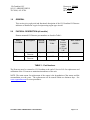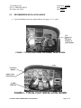
1
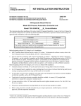
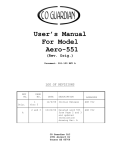
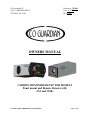
CO Guardian LLC
1951 E. AIRPORT DRIVE
TUCSON, AZ. 85706
Document: 353-002
Date: 11/15/05
REV ORIG.
OWNERS MANUAL
CARBON MONOXIDE DETECTOR MODELS
Panel mount and Remote Detectors (R)
(353 and 353R)
353 FAMILY MODEL OWNERS/INSTALLATION MANUAL
Page 1 of 22
CO Guardian LLC
1951 E. AIRPORT DRIVE
TUCSON, AZ. 85706
Document: 353-002
Date: 11/15/05
REV ORIG.
LOG OF REVISIONS
REV
NO.
PAGE
NO.
DATE
A
1 thru 18
11/15/05
353 FAMILY MODEL OWNERS/INSTALLATION MANUAL
DESCRIPTION
Initial Release
APPROVED
ASH VIJ
Page 2 of 22
CO Guardian LLC
1951 E. AIRPORT DRIVE
TUCSON, AZ. 85706
Document: 353-002
Date: 11/15/05
REV ORIG.
TABLE OF CONTENTS
Description
Cover Page
Log of Revisions
Table of Contents
Forward
1.0 General
2.0 Physical Descriptio
3.0 Leading Particulars
4.0 Scope
5.0 Service Facilities
6.0 Installation 353 Panel Mount
6.1 Installation 353R Remote Mount
6.2 Recommended Installation Areas
6.2.1 DB9 pinout Diagram
6.2.2 Installation Check 353
6.2.3 Installation Check 353R
7.0 Maintenance
8.0 Scheduled Maintenance
9.0 Weight and Balance
10.0 Limitation
11.0 Normal Procedure 353
11.1 Normal Procedure 353R
12.0 Performance
13.0 Emergency Procedures
14.0 Unit Failure Indication
15.0 RS232 Data Buss Options
16.0 Warranty
353 FAMILY MODEL OWNERS/INSTALLATION MANUAL
Page
1
2
3
4
5
5
6
7
8
8
9
10
11
11
11
12
13
13
14
14
14
14
15
16
16
17
Page 3 of 17
CO Guardian LLC
1951 E. AIRPORT DRIVE
TUCSON, AZ. 85706
Document: 353-002
Date: 11/15/05
REV ORIG.
FORWARD
This document provides information intended for use by persons who, pursuant to current
requirements, are qualified to install this equipment. Because equipment and system installations
vary depending on a particular aircraft, this document is intended only as a guideline. If further
information is required, contact:
CO Guardian, LLC
1951 E. Airport Drive
Tucson, AZ 85706
(520) 889-1177
(520) 889-8249 (f)
(800) 639-7139
www.Coguardian.com
We welcome your comments concerning this document. Although every effort has been made to
keep it free of errors, some may occur. When reporting a specific problem, please describe it
briefly and include the document number, the paragraph/figure/table number, and the page
number. Send your comments to the address above.
This unit is designed to be installed in Experimental Aircraft. If this unit is installed in a
certified aircraft, appropriate FAA approval is required prior to installation.
353 FAMILY MODEL OWNERS/INSTALLATION MANUAL
Page 4 of 17
CO Guardian LLC
1951 E. AIRPORT DRIVE
TUCSON, AZ. 85706
1.0
Document: 353-002
Date: 11/15/05
REV ORIG.
GENERAL
This section gives a physical and functional description of the CO Guardian CO Detector
indicator as installed in a typical reciprocating engine type aircraft.
2.0
PHYSICAL DESCRIPTION (all models)
Remote mounted CO Detector part numbers are listed in Table 1.
PART
NUMBER
353
353R
14/28
Cabin
Pressure
warning
(10K,
12.5K and
14K
yes
yes
14/28
yes
yes
Description
SERVIC
E LIFE
POWER
Volts
Panel mount
Detector
Remote mount
Detector
5 years
5 years
DATA BUSS
(RS232)
TABLE 1 - Part Numbers
The Detector must be returned to CO Guardian at the end of Service Life for replacement and
calibration of the CO sensor to maintain airworthiness of the unit.
NOTE: The main reason for replacement of the sensor is the degradation of the sensor and dirt
accumulation over the years. The replacement will be turned within two business days. See
www.coguardian.com for exact procedures.
353 FAMILY MODEL OWNERS/INSTALLATION MANUAL
Page 5 of 17
CO Guardian LLC
1951 E. AIRPORT DRIVE
TUCSON, AZ. 85706
3.0
Document: 353-002
Date: 11/15/05
REV ORIG.
LEADING PARTICULARS
Table 2 lists the CO Detector leading particulars and below are specs.
LEADING PARTICULARS/SPECS
PARAMETER
SPECIFICATION
PHYSICAL
Dimensions (approximate)
3.75” long. X 1.50”W in x 1.20” H
Weight (actual)
4.0 oz.
ENVIRONMENTAL
Cooling
Passive
Temperature and Altitude
Temperature
Non-operating high temperature
+85 °C
Non-operating low temperature
-55 °C
Operating high temperature
+55 °C
Operating low temperature
-20 °C
Temperature Variation
Altitude
25,000’ for 353P and 353PR
Humidity
95%
POWER REQUIREMENTS
Power – 14/28 VDC Models
Nominal 9.0 vdc to 30.3vdc
Dissipation (maximum)
<1 watt
TABLE 2 - Leading Particulars
353 FAMILY MODEL OWNERS/INSTALLATION MANUAL
Page 6 of 17
CO Guardian LLC
1951 E. AIRPORT DRIVE
TUCSON, AZ. 85706
4.0
Document: 353-002
Date: 11/15/05
REV ORIG.
SCOPE (all models)
The Model 353 family of Carbon Monoxide Detectors are designed to detect,
measure, and provide a visual alert to the crew of Reciprocating Engine type
aircraft before the cockpit level of carbon monoxide (CO) reaches a critical level.
The installation consists of a single carbon monoxide detector indicator operating
on aircraft DC power (14v or 28v). The aircraft supplied power and aircraft wiring
is protected by a 2 ampere, resettable, trip free, type circuit breaker. The Carbon
Monoxide Detector recommended location is behind the existing aircraft
instrument panel.
The CO Detector installation consists of the CO Detector, a Test/Reset button,
and a required amber ALERT annunciator light mounted on the cockpit
instrument panel.
The carbon monoxide alarm level is calibrated to provide a visual alert within 5
minutes or less whenever the carbon monoxide level reaches 50 parts per million
(PPM) by volume or greater. The warning time is shortened at higher levels of
CO concentrations and becomes approximately instant should the carbon
monoxide level reach 400 parts per million by volume (PPM) or greater.
In case of a carbon monoxide alert, the pilot will receive an amber Alert
annunciator light that is mounted on the Pilot's instrument panel on remote
mounts and on the unit itself on the panel mount. The visual alert will remain until
the carbon monoxide level is reduced below the alert level. The indicator is
automatically reset when the CO level drops below 50 PPM. There is a threeminute delay at startup to stabilize the sensor before the unit will accurately
sense CO levels.
The 353 and 353R have a built in pressure compensation sensor to detect cabin
altitude changes up to 25,000 to give a better accuracy in CO Detection. These
models also alarm if the cabin altitude goes above 10,000 feet for 10 seconds,
12,500 for 10 seconds and stays on over 14,000 feet. These models also have
RS232 output for display data of CO Level on Garmin GNS480 and other
manufacturers.
353 FAMILY MODEL OWNERS/INSTALLATION MANUAL
Page 7 of 17
CO Guardian LLC
1951 E. AIRPORT DRIVE
TUCSON, AZ. 85706
5.0
Document: 353-002
Date: 11/15/05
REV ORIG.
SERVICE FACILITIES (all models)
The operator can service all other components of the installation at an FAA certified
Repair Station or by A&P mechanic. CO Detectors must me returned to CO Guardian for
repair calibration or overhaul.
NOTE
The sensor requires special gases for testing. If any discrepancies are
found with the unit during installation or during the operational service life,
the unit must be returned to CO Guardian for repair or replacement. The CO
Detector unit must be returned to the manufacturer for CO sensor
replacement and re-calibration at the end of the service life applicable to
the units part number.
6.0
INSTALLATION 353 using drawing (353-001 Rev. Orig or later)
The following documents the installation criteria of the Model 353 Carbon Monoxide
Detector Installation (Panel Mount):
a. Choose a location behind the instrument panel for the installation of the CO Detector.
Choose a location with space available that also meets the following criteria. A typical
installation is shown in attached drawing. The unit can be installed on any side of the
instrument panel.
b. Insure that the area around the CO Detector panel location will permit unrestricted
airflow through the unit.
c. Install in a cockpit area not exposed to excessively dusty or dirty conditions.
d. Insure that the air intake on the front of the CO Detector is not obstructed in any manner.
e. Install the CO Detector in a location without high or disturbed airflow movement. The
CO Detector will detect the presence of CO more effectively if the unit does not have air
blowing over it.
f. Insure that the CO Detector installation area meets the temperature and humidity ranges
listed in the List of Particulars specifications. Temperature and humidity conditions
outside the specification may affect the sensitivity of the detector.
353 FAMILY MODEL OWNERS/INSTALLATION MANUAL
Page 8 of 17
CO Guardian LLC
1951 E. AIRPORT DRIVE
TUCSON, AZ. 85706
Document: 353-002
Date: 11/15/05
REV ORIG.
g. Install the TEST/RESET and the amber ALERT annunciator in a location within the
pilot's direct field of vision and within normal pilot's reach. Note: see MFG MFD
installation manual if TEST/RESET and the amber ALERT annunicator unit will not be
installed and the data will be displayed thru the RS232 interface with MFD. See
Manufacturers manuals for proper wiring guidance.
h. The remote unit can be remotely installed behind the instrument panel up to six inches
from the panel air sampling holes. Verify there are no bends that may obstruct air flow to
the unit.
i. The panel mount unit can be installed anywhere around the instrument panel within pilots
reach. Verify that there is no obstruction of airflow to the unit.
j.
6.1
INSTALLATION 353R using drawing (353-001 Rev. Orig or later)
Installation 353R using drawing 353-001 Rev. Orig or later
a. Choose a location behind the instrument panel for the installation of the CO Detector.
Choose a location with space available that also meets the following criteria. A typical
installation is shown in the attached drawing. The unit can be installed on any side of the
instrument panel.
b. Insure that the area around the CO Detector panel location will permit unrestricted
airflow through the unit.
c. Install in a cockpit area not exposed to excessively dusty or dirty conditions.
d. Insure that the air intake on the front of the CO Detector is not obstructed in any manner.
e. Install the CO Detector in a location without high or disturbed airflow movement. The
CO Detector will detect the presence of CO more effectively if the unit does not have air
blowing over it.
f. Insure that the CO Detector installation area meets the temperature and humidity ranges
listed in the List of Particulars specifications. Temperature and humidity conditions
outside the specification may affect the sensitivity of the detector.
g. Install the TEST/RESET and the amber ALERT annunciator in a location within the
pilot's direct field of vision and within normal pilot's reach. Note: see MFG MFD
installation manual if TEST/RESET and the amber ALERT annunicator unit will not be
installed and the data will be displayed thru the RS232 interface with MFD.
353 FAMILY MODEL OWNERS/INSTALLATION MANUAL
Page 9 of 17
CO Guardian LLC
1951 E. AIRPORT DRIVE
TUCSON, AZ. 85706
6.2
Document: 353-002
Date: 11/15/05
REV ORIG.
RECOMMENDED INSTALLATION AREAS
•
Typical installation areas are depicted below in Figurers 1, 2, 3, and 4.
CO
Detectors
locations
Remote or
panel mount
FIGURE 1 - TYPICAL RIGHT HAND INSTRUMENT PANEL SHOWN
Test/Reset
Button
Amber Alert
Annunciator
2 AMP
CIRCUIT
FIGURE 2 - TYPICAL PILOT INSTALLATION SHOWN
353 FAMILY MODEL OWNERS/INSTALLATION MANUAL
Page 10 of 17
CO Guardian LLC
1951 E. AIRPORT DRIVE
TUCSON, AZ. 85706
Document: 353-002
Date: 11/15/05
REV ORIG.
6.2.1 DB9 PINOUT INSTRUCTIONS
353 and 353R
PIN
FUNCTION
1
14 or 28 VDC Power Input
2
Remote Test/Reset Switch
3
Remote Test/Reset Switch
4
CO Alert Relay
5
Power Ground
6
CO Alert Relay 2
7
RS232 TX Output
8
RS232 TX Input
9
Cabin Pressure Relay (optional)
CO DETECTOR CONNECTOR PINS AND FUNCTION
6.2.2 INSTALLATION CHECKS 353
a. With the CO Detector disconnected from the aircraft harness, conduct a continuity check
of the added aircraft wiring.
b. Turn ON the aircraft Battery Switch. Close the CO DETECT circuit breaker and measure
aircraft voltage between pins 1 and 5 of the CO Detector connector.
c. Connect the CO Detector connector to the aircraft harness. Turn aircraft Battery Switch
ON. Close CO DETECT circuit breaker.
d. Operational check the unit by depressing the CO TEST/RESET switch and verifying the
remote alert light operation. Remote Amber Alert light should flash twice.
e. Verify the unit can be shut off with the CO DETECT circuit breaker.
f. Determine the moment arm for the installed CO Detector location and record in aircraft
weight and balance manual. CO Detector weight is 4.0 oz.
6.2.3 INSTALLATION CHECKS 353R
a. With the CO Detector disconnected from the aircraft harness, conduct a continuity check
of the added aircraft wiring.
353 FAMILY MODEL OWNERS/INSTALLATION MANUAL
Page 11 of 17
CO Guardian LLC
Document: 353-002
1951 E. AIRPORT DRIVE
Date: 11/15/05
TUCSON, AZ. 85706
REV ORIG.
b. Turn ON the aircraft Battery Switch. Close the CO DETECT circuit breaker and measure
aircraft voltage between pins 1 and 5 of the CO Detector connector. Pull the CO
DETECT circuit breaker. Verify the voltage between pins 1 and 5 is OFF.
c.
Close the CO DETECT KEEP ALIVE circuit breaker and measure aircraft voltage
between pins 9 and 5 of the CO Detector connector. Turn aircraft Battery switch OFF.
Measure aircraft voltage between pins 1 and 5 of the CO Detector connector.
d. Connect the CO Detector connector to the aircraft harness. Turn aircraft Battery Switch
ON. Close CO DETECT circuit breaker.
e. Operational check the unit by depressing the CO Test/Reset switch and verifying the
remote alert light operation if installed. Remote Amber Alert light should flash twice.
f. Verify the unit can be shut off with the CO DETECT circuit breaker.
g. Determine the moment arm for the installed CO Detector location and record in aircraft
weight and balance manual. CO Detector weight is 3.5 oz.
7.0
MAINTENANCE INSTRUCTIONS (ALL MODELS)
The carbon monoxide detector and associated equipment consist of certain parts, which
do not require periodic scheduled servicing or periodic scheduled preventive
maintenance. At every power up the system will go through a self-diagnostic check.
WARNING: If all Models show a flashing remote Amber light every 4
seconds, return the unit to CO Guardian for repair or replacement. See
MFG Manual if Remote light is displayed on the MFD.
Field repair or service is allowable on all of the installed system
components except for the CO Detector Indicator itself. The CO Detector
must be returned to CO Guardian, LLC for all service.
The aircraft wiring harness, circuit breaker, Alert annunciator, and Test/Reset switch
shall be included maintenance instructions for general visual inspections for system
integrity, installation security, corrosion and chaffing.
353 FAMILY MODEL OWNERS/INSTALLATION MANUAL
Page 12 of 17
CO Guardian LLC
1951 E. AIRPORT DRIVE
TUCSON, AZ. 85706
8.0
Document: 353-002
Date: 11/15/05
REV ORIG.
SCHEDULED MAINTENANCE
Scheduled Maintenance Program tasks to be added to the aircraft operator's appropriate
airplane maintenance program are as follows:
MAINTENANCE TASK
INTERVAL
a.
Recommended Periodic Scheduled Servicing Tasks:
None Required.
b.
Recommended Periodic Scheduled Preventative Maintenance Each time the unit is turned ON.
test/checks to determine system condition and/or latent failures:
Note:
Be sure the vent on the faceplate is free of obstructions.
Any failures of the system are evident to the pilot through a
flashing remote Amber light approximately every 4
seconds.
c.
Recommended Periodic Inspections:
None Required.
d.
Recommended Periodic Structural Inspections
None Required.
e.
Required CO Sensor replacement and calibration.
At end of Service Life (5 Years)
NOTE
The unit must be returned to the manufacturer for sensor
replacement and recalibration at the end of the unit service life.
NO FIELD SERVICE OR OVERHAUL OF MODELS IS AUTHORIZED.
9.0
WEIGHT AND BALANCE / EQUIPMENT LIST (ALL MODELS)
The Aero 353’s CO Detector installation weighs 0.125 lbs. Reference the aircraft
weight and balance manual for moment arm.
353 FAMILY MODEL OWNERS/INSTALLATION MANUAL
Page 13 of 17
CO Guardian LLC
1951 E. AIRPORT DRIVE
TUCSON, AZ. 85706
10.0
Document: 353-002
Date: 11/15/05
REV ORIG.
LIMITATIONS (ALL MODELS)
The 353 family of Detectors may not replace any existing instrument or indicator
required by the type design or operating limits.
11.0
NORMAL PROCEDURES 353
When the airplane master battery switch is selected ON, the Remote CO Detector goes
through a self-test routine. The self-test checks for functionality of critical components
such as the CO sensor, temperature sensor, pressure sensor, and integrity of the system
and remote display will remain off if everything working properly. The RS232 MFD will
show no CO on the CO Detector page.
11.1
NORMAL PROCEDURES 353R
You will notice the following test sequence:
•
The Amber CO ALERT light will flash twice and then remain OFF until there is
a CO ALERT, a failure of the unit, or another self-test is performed.
A self-test can be performed when desired by depressing the TEST/RESET button.
12.0
PERFORMANCE
No Change
353 FAMILY MODEL OWNERS/INSTALLATION MANUAL
Page 14 of 17
CO Guardian LLC
1951 E. AIRPORT DRIVE
TUCSON, AZ. 85706
13.0
Document: 353-002
Date: 11/15/05
REV ORIG.
EMERGENCY PROCEDURES
If the CO Detector ALERT annunciator activates in flight, press the TEST/RESET button
to reset the alert annunciator. If the ALERT light continues to illuminate:
•
•
•
•
•
•
Shut off the heater, air conditioning or any other opening to the engine compartment.
Open a fresh air source immediately.
Don't smoke.
Use 100% oxygen, if possible.
Land as soon as conditions permit.
Be sure the source of the contamination is corrected before further flight.
NOTE: The remote Amber light will stay on until the CO level goes below
50 parts per million (PPM) by volume of carbon monoxide concentration.
SEE MFD manual if the “ALERT” display is integrated with the
Manufacturers MFD.
DO not recycle the unit through the circuit breaker. A three-minute delay is
required for the CO sensor to stabilize after each power-up in the -001
through -004 P/N units.
353 FAMILY MODEL OWNERS/INSTALLATION MANUAL
Page 15 of 17
CO Guardian LLC
1951 E. AIRPORT DRIVE
TUCSON, AZ. 85706
14.0
Document: 353-002
Date: 11/15/05
REV ORIG.
UNIT FAILURE INDICATION:
A failure of the CO Sensor, Temperature Sensor, or the Micro-controller will result in the
following failure indications:
•
The remote Amber light will flash at an approximate rate of one flash each four
(4) seconds until the failure is cleared or power is removed from the unit. NOTE:
SEE MFG manual if the fault data is integrated with the MFG MFD for fault
analysis.
In case of a failure indication, attempt to clear the failure condition by resetting
the CO Detector. Should the failure condition continue, remove the CO Detector
power by pulling the CO Detector circuit breaker.
15.0
RS-232 DATA BUSS OPTION
The RS-232 Data Buss option is currently available on numerous MFD units. The RS232 data buss output will couple CO Detector status information to electronic display
systems with RS-232 input capability.
See Multi-Function display manufacturers Installation Manual for interface guidance.
The CO ALERT can be reset through the RS-232 interface provided the Multi-Function
system contains the reset capability.
353 FAMILY MODEL OWNERS/INSTALLATION MANUAL
Page 16 of 17
CO Guardian LLC
1951 E. AIRPORT DRIVE
TUCSON, AZ. 85706
16.0
Document: 353-002
Date: 11/15/05
REV ORIG.
Warranty
WARRANTY COVERAGE: CO GUARDIAN LLC. WARRANTS TO THE ORIGINAL CONSUMER
PURCHASER, THAT THIS DETECTOR WILL BE FREE OF DEFECTS IN MATERIAL AND
WORKMANSHIP FOR A PERIOD OF ONE (1) YEAR FROM DATE OF PURCHASE. THE
MANUFACTURER'S LIABILITY HEREUNDER IS LIMITED TO REPLACEMENT OF THE
PRODUCT, REPAIR OF THE PRODUCT OR REPLACEMENT OF THE PRODUCT WITH A
REPAIRED PRODUCT AT THE DISCRETION OF THE MANUFACTURER. THIS WARRANTY IS
VOID IF THE PRODUCT HAS BEEN DAMAGED BY ACCIDENT, UNREASONABLE USE,
NEGLECT, TAMPERING OR OTHER CAUSES NOT ARISING FROM DEFECTS IN MATERIAL
OR WORKMANSHIP.
THIS WARRANTY EXTENDS TO THE ORIGINAL CONSUMER
PURCHASER OF THE PRODUCT ONLY.
Warranty Disclaimers: Any implied warranties arising out of this sale, including but not limited to
the implied warranties of description, merchantability and fitness for a particular purpose, are
limited in duration to the above warranty period. In no event shall the Manufacturer be liable for
loss of use of this product or for any indirect, special, incidental or consequential damages, or
costs, or expenses incurred by the consumer or any other user of this product, whether due to a
breach of contract, negligence, strict liability in tort or otherwise. The manufacturer shall have
no liability for any personal injury, property damage or any special, incidental, contingent or
consequential damage of any kind resulting from gas leakage, fire or explosion.
Some states do not allow limitations on how long an implied warranty lasts, so the above limitation may
not apply to you.
Some states do not allow the exclusion or limitation of consequential or incidental damages, so the above
limitations or exclusions may not apply to you.
Legal Remedies: This warranty gives you specific legal rights and you may also have other rights that
vary from state to state.
Warranty Performance: During the above warranty period, your product will be replaced with a
comparable product if the defective product is returned, postage prepaid, to CO Guardian, Customer
Service Department, 1951 East Airport Drive, Tucson, AZ 85706, together with proof of purchase date.
Please include a note describing the problem when you return the unit. The replacement product will be
in warranty for the remainder of the original warranty period or for six months whichever is longer.
Other than the cost of postage, no charge will be made for replacement of the defective product.
Important: Do not attempt to open unit. If unit is opened, warranty will be void.
Your Carbon Monoxide Alarm is not a substitute for property, disability, life or other insurance of any
kind. Appropriate insurance coverage is your responsibility. Consult your insurance agent.
NOTE
The warranty will be void if the unit is opened or tampered with
353 FAMILY MODEL OWNERS/INSTALLATION MANUAL
Page 17 of 17