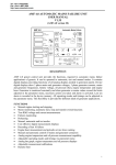
1
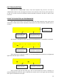
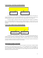
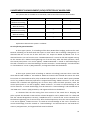
ML65X LCD Screen Usage Lift position and fault datas are screened on LCD top line on ML65X card. When the car is on stand by position, floor number is on LCD lower line. L a m p O n ‐ W a i t C a l l F : 0 6 Car lamp is ON and call is waited Floor the car stopped After the maintenance working hour After the maintenance working day W a i t C a l l F : 1 2 D 0 2 3 H 1 2
Car lamp is OFF and call is waited When the car is moving, on the left side of LCD top line, there is target floor and on the right side of LCD top line, there are movement direction, speed and fault datas. On the lower line, the floor that the car position at the moment is screened. Target floor T r g : 0 5 F : 0 2 U p H i g h S . Up direction high speed movement
Floor the car stopped Target floor level T r g : 0 5 F : 0 2 U p L o w S . Up direction low speed movement
1 ML65X Button Usage Explanations There are four buttons at the right side of ML65X card. Some functions are appointed to these buttons except the situation that the car is stopped, stop signal is off or stop signal is cut and re‐applied and inspection mode. ENTER BUTTON (Red) : Manual movement mode is started when pressed this button. At this situation, if safety circuit is OK, the car is moved with UP and DOWN buttons. Soft stop is done at the end of the movements for Speed Control Systems. ESC button must be pressed to exit Manual Movement mode. UP BUTTON (Brown): Situation screens are shown in order when pressed this button. The explanations related this function will be done below. DOWN BUTTON (Brown): Car calls function is started when pressed this buton. The explanations related this function will be done below. ESC BUTTON (Black): Registered fault observing function is started when pressed this button. The explanations related this function will be done below. SITUATON SCREENS TRACING Situation screens datas can be reached with up buton and looked at between the screens. Communication Screen C o m m u n i c a . S t a t u s C = ± I n t = ± ± ± ± D = ±
Shown that extra call cards (INT65/1‐2‐3‐4) are exist Shown that car serial communication card (SERI65) is exist Shown that doublex communication is exist Display Short Circuit Screen D i s p S h o r t C i r c u i t N o t Shown that short circuit on which display segment/s or not 2 Door Situation and Signals Screen A D o o r A C = * Shown that “OPEN” signal exist O p e n e d K A P A = ‐ Shown that A Door situation Shown that “CLOSE” signal exist B D o o r A C = ‐ Shown that “OPEN” signal exist I s N o t H e r e
K A P A = ‐ Shown that B Door situation Shown that “CLOSE” signal exist Call Screen 0 . . 1 5 C a r . . . . . . . . . . .
C a l l s . . . . .
Shown that car calls Total Run Screen T o t a l R u n 0 0 0 0 0 0 0 Shown that total run number
3 Run After Maintenance Screen R u n A f t e r M a i n t . 0 0 0 0 0 0 0 0 Shown that total run after maintenance
Remain Day To Maintenance Screen M a i n t . R e m a i n 2 4 0 D a y
Shown that the remaining day to maintenance
MLKR1 Fault Screen L a s t M L K R 1 F a u l t N o F a u l t Shown that the last fault about MLKR1 card
ENTER CAR CALL Manual car call can be entered to the lift with down button. Enter Call Screen 0 _ _ C a l l E n t e r _ _ 1 5
. . . . . . . . . . . . . . . .
Shown that floor calls 4 Dots on the screen indicate floor numbers in order. Floor that will be given call is selected with cursor and put “+” sign with “ENTER” on the floor number. More than one call, the other floors are selected the same. 0 _ _ C a l l E n t e r _ _ 1 5
. . . + . . . . + . . + . . . .
To exit the function, it must be pressed to “ESC” button. E N T = O k E S C = C a n c l . . . + . . . . + . . + . . . .
On the screen, registrations are canceled with “ESC” button or registrations are confirmed with “ENTER” button and exit from the function. ML65X Registration Faults Tracing When the lift is working, some faults being in the system are registered with the direction, station, day and hour datas. It can be registered the last 16 faults. When the car is stopped, if ESC button is pressed except the situation that the car is stopped, stop signal is off or stop signal is cut and re‐applied and inspection mode, fault tracing function is started. Out of service lamp is ON. L o c k h . 0 1 S i g n a l E r r o r G = 0 2 8 S = 1 2 >
5 When the function is started, the first fault shown at the screen is the last fault. If another fault is not exist “ No Fault “ message is screened. It is get to trace the faults by pressing UP and DOWN buttons. At the tracing time, the number of the faults are not related to occuring time of the faults before or later. Day and hour determinates the occuring order of the faults. When any fault is screened, if ENTER button is pressed, during 2 sec. the direction and station of the fault are shown at the screen. U p F : 0 2
When ESC button is pressed or detected the car or control panel inspection key, fault tracing function is end. At the programming mode, if enter to “G.Maint.Settings” section and select YES in (G03) parameter “Maintenanced?” menu, registered faults are deleted. ML65X General Fault Explanations ERROR SCREEN DISPLAY Lock SignalError MaxHighSpeedTime MaxLowSpeedTime Contactor Fault 817=0 818=0 DoorOpenLongTime StopBut.LongTime EXPLANATION When the lift will move, the situation that the lock signal is not detected at the lock wait time after the pomp pulled. The fault is registered with the direction data. At this situation the calls are deleted and lift is out of service during 10 sec. While the lift is high speed movement, the situation that floor changing is not detected from pulse bi‐stable in adjusted time at parameter. At this situation the calls are deleted and fault is registered with direction data. The lift is blocked with lightening the out of service lamp. While the lift is low speed movement, the situation that jf signal is not detected in adjusted time at parameter. At this situation the calls are deleted and fault is registered with direction data. The lift is blocked with lightening the out of service lamp. The situation that KRC contactor control input is not detected in 2 sec. after the relays that pulls the contactors are dropped. At this situation the calls are deleted and the fault is registered. The lift is blocked with lightening the out of service lamp. The situation that both necessary cutter is not exist at the same time. At this situation the calls are deleted and the lift is out of service till the one of the cutter is detected. The situation that the door is open till the end of the adjusted time at the door maximum time parameter. At this situation the calls are deleted and the lift is out of service till the door signal is detected. The situation that stop signal is remained cut till the end of the adjusted time at the door maximum time parameter. At this situation the calls are deleted and the lift is out of service till the stop signal is detected. 6 R PhaseError S PhaseError T PhaseError R,S PhaseError R,T PhaseError S,T PhaseError R,S,T PhaseError PhaseOrderError Driver Fault No 817 Signal No 818 Signal The situation that one the phases is not exist. If this situation is occured while the lift is moving, the car is stopped by locating a call to the nearest floor in the same direction. If there is not a phase when the lift is stopped at the nearest floor or the car is stopped, the calls are deleted and the lift is out of service. The situation that two ot three of the phases are not exist. If the car is moving, it is stopped; the calls are deleted and the lift is out of service. The situation that the phases orders connected to phase protection terminals (R, S, T) are wrong. At this situation the calls are deleted and the lift is out of service (Phase order is only controlled when the lift is stopped). When one of the the gearless rescue options is selected, the driver fault control is done from EIN input. When this input is not detected, this fault warning is shown at lcd screen. Before coming the bottom floor, the situation of cutting 817 signal. The fault is registered with the direction data. At this situation the calls are deleted and lift is out of service during 10 sec. Before coming the top floor, the situation of cutting 818 signal. The fault is registered with the direction data. At this situation the calls are deleted and lift is out of service during 10 sec. Notes : 1‐ Controls that phases are not exist are shown at screen during ML65X card has power. 2‐ Phase order fault is only controlled when the lift is stopped. 3‐ If one of the lifts is out of service at doublex working because of any fault, external calls appointed on this lift are transfered to the other lift. ML65X – MLKR1 Door Bridging Fault Descriptions
If MLKR1 door bridging card is used with ML65X card; it can be done re‐levelling and advanced door opening. When door bridging operation is done, if the faults that descriptions are belowed are occured, fault message is shown at lcd screen and registered to the memory. At this situation the lift is blocked by lightening out of service lamp. After the block operation, when the control panel power is cut and re‐applied, “MLKR1 ErrorExist” is traced on lcd and blockage of the card is continues. To cancel the blockage, must be entered to “J.GeneralSetings” and selected YES on “DelMLKR1Error” menu in (J05) parameter, and registered fault must be deleted. To look the registered fault, UP button must be used that is explained in button descriptions. 7 FAULT SCREEN DISPLAY EXPLANATION ML1‐ML2 Shunted ML1 and ML2 inputs are short circuit. RML1‐2NotPickUp RML1‐2 Not Drop Not Bridged 140OnAfterBridge ML1 Shunt To 100 ML2 Shunt To 100 ML1=100,ML2=100 ML1 Missing ML2 Missing ML1‐2 Missing WHAT TO DO Check ML1 and ML2 inputs that they are short circuit or not. Use different switches for ML1 and ML2 re‐levelling zone mono‐stable swithes. There is no situation signal of 1‐Check ‘’ST’’ (RML1 or RML2 RML1 or RML2 bridging safety situation signal) terminal connection between ML65X relays on MLKR1 card. and MLKR1 cards. 2‐If there are ML1 and ML2 signals, check RML3 relay is dropped at the start of bridging and then RML1, RML2 relays are dropped. There is always situation signal 1‐ Check ‘’ST’’ terminal on ML65X and MLKR1boards is of RML1 or RML2 bridging not short circuit with 100. safety relays on MLKR1 card. 2‐ Check RML1 or RML2 relays are not pulled although there are no ML1 or ML2 signals. Check the connections The signal is not detected between “SF1” and “SF2” from ‘’140’’ input although bridging operations are done. terminals on MLKR1 card to “120” and “140” signals. Although the end of bridging Check RE relay on MLKR1 card operation, signal is detected is dropped. from ‘’140’’ input. 1‐Check ML1 and/or ML2 Detecting ML1 and/or ML2 input is not short circuit with signal when the lift is at low 100. speed movement because of 2‐Take the zone that the car detecting the target floor. passed to low speed to the front than the re‐levelling zone. Check ML1 and/or ML2 Not detecting ML1 and/or inputs. ML2 signal when the car is stopped at call floor. 8 ML1 ve ML2 mono‐stable swithes are shown how to be located below that will be used in the lift system do the re‐levelling when the door is open with using MLKR1. Mono‐stable switches 30 cm ML1 5cm ML2 Ribbon magnet Levelling Magnet Location Mono‐stable swithes using for UP and DOWN levelling and ribbon magnets are shown how to be located below that will be used in the lift system do the re‐levelling when the door is open with using MLKR1. 10cm Exact Floor Level 2cm 2,5cm
5cm
2,5cm
UP levelling mono‐stable switch DOWN levelling mono‐stable switch 2cm
10cm 9 EXIT FROM INSPECTION When the lift is “INSPECTION” mode, if exit with Inspection Key, the lift is stil stays in “INSPECTION” mode. For this 130 signal must be cut once. Because of the security, when operator is on the car, in state of exit from inspection with unintendent movement, the door is need to open once time. DOOR TYPES SELECTION IN PROGRAMMING Door types on each floors can be selected A side and B side seperately. Door types can be indicated as; CarDo. (only car door automatic), F.Auto (floor +car door automatic), NoDoor (there is no door). C 1 : D o o r T y p e S e t A
F l r 0 0 C a r D o . Floor number that will be selected A door type selecting screen Door type that will be selected for each floor For selection, with lightening left arrow by pressing ENTER button, required floor is selected. C 1 : D o o r T y p e S e t A
F l r 0 0 C a r D o . Floor number that will be selected Door type that will be selected for each floor If floor door type is required to change, it is pressed ENTER button second time and lightened right arrow and door type is selected. C 1 : D o o r T y p e S e t A
F l r 0 0 C a r D o . Floor number that will be selected Door type that will be selected for each floor Also if all door types are the same type, “All” on the left side floor screen is selected, it is pressed ENTER button and door type is selected with second arrow on the right side and all floors door types are defined the same type. 10 FLOOR DISPLAY SELECTION IN PROGRAMMING D 1 : F l o o r D i s p . S e t F l r 0 0 D i s p 0
Floor number that will be selected Display trace selection for each floor It is used for trace type selection that is required to be traced on floor for every floor. To change the parameter; first, by pressing ENTER button, floor is selected with arrow on left side. By pressing ENTER button again, display that will be traced is adjusted with arrow on right side. If any floor display is adjusted a number value and the other floors displays are required to sort, it is pressed ENTER button during 2 seconds. “ENTER forSorting” is started to flash on LCD bottom line. At this situation if it is confirmed by ENTER, all floor displays are sorted. ESC cancels the operation. FLOOR LEVEL CORRECTIONS IN PROGRAMMING I 8 : F l . L v l C o r r e c t F l r 0 0 0 5 m m
Floor selection that will be done correction Distance correction for each floor For each floor in shaft learning, at the situation of the car doesn’t stop the floor level, it is used for accuracy correction. To enter the parameter, floor is selected with the arrow on left side by pressing ENTER button and by pressing again, distance correction is done as (‐) or (+) value with arrow on the right side. Distances are indicated one by one or by using “All” option in the left side of parameter, the same correction for all floors can be entered. INSPECTION (RV) RELAY FUNCTIONS 10A relay which open, close and common tip are given to the terminal is located to ML65X card. There are two type functions of this relay. It is run as INSPECTION relay when MLSERI65 car serial communication card (CarSerialcard) parameter is “Active” and it is run as CAR LAMP relay when the parameter is “Cancel”. These functions can not be changed. If this relay will be used as CAR LAMP relay, close contact must be used. 11 UNINTENDENT CAR MOVEMENT (UCM) DETECTION OF ML65X CARD For systems that are suitable to A3 standards, cards that will be used are shown below: System Geared Without Re‐levelling Geared With Re‐levelling Gearless Without Re‐levelling Gearless With Re‐levelling Hydraulic ML65X MLA3 MLKR1 * * * * * * * ‐ ‐ ‐ ‐ * ‐ * * Explanations about these systems are below. For the lifts has geared machine: In these type systems, if re‐levelling will be done, MLKR1 door bridging card must be used. Because relevelling can be done with door opene or close. When the re‐levelling is being done, it si detected that the car exit out of door zone with “ST” output on MLKR1 by ML65X card. If it is detected that the car exit from this zone “UCMErrorDetected” is traced on lcd and stopped running. At this situation lift is blocked with lightening out of service lamp. After the block operation, when the control panel power is cut and re‐applied, “UCMErrorDetected” is traced on lcd and blockage of the card is continues. To cancel the blockage, must be entered to “J.GeneralSetings” and selected YES on “Del UCM Error” menu in (J06) parameter, and registered fault must be deleted. In these type systems (with re‐levelling or without re‐levelling); OSG must have a steel bar which blocks UCM suitable to A3 standards. MLA3 card controls the selenoid that moves this steel bar on OSG. It is detected that safety relay on MLA3 card dropped or not with “MNT” input by ML65X card. If any problem is detected, operation is stopped with writing “MLA3 Card Error” on lcd. At this situation lift is blocked with lightening out of service lamp. After the block operation, when the control panel power is cut and re‐applied, “MLA3 Card Error” is traced on lcd and blockage of the card is continues. To cancel the blockage, must be entered to “J.GeneralSetings” and selected YES on “Del UCM Error” menu in (J06) parameter, and registered fault must be deleted. It is detected that the info coming from close contact of the switch that is dropping and pickin up with the selenoid on OSG and the selenoid dropped or not by ML65X card. If it is detected that the selenoid dropped not correctly, “OSG/Brake Error” is traced on lcd. At this situation lift is blocked with lightening out of service lamp. After the block operation, when the control panel power is cut and re‐applied, “UCM Error Exist” is traced on lcd and blockage of the card is continues. To cancel the blockage, must be entered to “J.GeneralSetings” and selected YES on “Del UCM Error” menu in (J06) parameter, and registered fault must be deleted. 12 For the lifts has gearless machine: In these type systems, if re‐levelling will be done, MLKR1 door bridging card must be used. Because relevelling can be done with door opene or close. When the re‐levelling is being done, it is detected that the car exit out of door zone with “ST” output on MLKR1 by ML65X card. If it is detected that the car exit from this zone “UCMErrorDetected” is traced on lcd and stopped running. At this situation lift is blocked with lightening out of service lamp. After the block operation, when the control panel power is cut and re‐applied, “UCMErrorDetected” is traced on lcd and blockage of the card is continues. To cancel the blockage, must be entered to “J.GeneralSetings” and selected YES on “Del UCM Error” menu in (J06) parameter, and registered fault must be deleted. In lift systems has a gearless machine, it is not needed to use MLA3 card. It is detected that the info coming from close contact of the switch that is dropping and pickin up with motor brake and the brake dropped or not by ML65X card. If it is detected that the brake dropped not correctly, “OSG/Brake Error” is traced on lcd. At this situation lift is blocked with lightening out of service lamp. After the block operation, when the control panel power is cut and re‐applied, “UCM Error Exist” is traced on lcd and blockage of the card is continues. To cancel the blockage, must be entered to “J.GeneralSetings” and selected YES on “Del UCM Error” menu in (J06) parameter, and registered fault must be deleted. For hydraulic lifts: In these type systems; because of not existing OSG, it is not needed to use MLA3 card. In kydraulic units suitable to A3 standards, there is one A3 protection valve. In down direction movement, tis valve is being dropped with down landing valve. In hydraulic with re‐levelling systems, while re‐levelling operation, it is detected that the car exit out of door zone with “ST” output on MLKR1 by ML65X card. If it is detected that the car exit from this zone “UCMErrorDetected” is traced on lcd and stopped running. At this situation lift is blocked with lightening out of service lamp. After the block operation, when the control panel power is cut and re‐applied, “UCMErrorDetected” is traced on lcd and blockage of the card is continues. To cancel the blockage, must be entered to “J.GeneralSetings” and selected YES on “Del UCM Error” menu in (J06) parameter, and registered fault must be deleted. 13 Manual test for unintendent car movement: In systems that are used MLKR1 card; there are UP and DOWN direction test menus of ML65X card for testing the detection of unintendent car movement (UCM) correctly. Before doing UP direction test operation, car is taken to the floor level of the floor that is under the the topper floor. Than to start the test, must be entered to “J.GeneralSetings” and selected YES on “UCM Up Test” menu in (J07) parameter. Before doing DOWN direction test operation, car is taken to the floor level of the floor that is on the bottom floor. Than to start the test, must be entered to “J.GeneralSetings” and selected YES on “UCM Down Test” menu in (J08) parameter. These test operations simulates unintendent car movement (UCM) error that occures when the door is open normally as closed door. During the test, car is moved with low speed to the test direction. When the car is exit from the door zone, unintendent car movement (UCM) error occures and reset operations of the fault must be applied the same. AUTO TUNING: To do auto tuning as brake is closed in gearless systems, must be entered to “J.General Settings” and selected YES on “Auto Tuning” menu in (J09) parameter. So in INSPECTİON mode, during 100 seconds after the first movement, OSG/Brake Control is not done. IMPORTANT WARNING !
CANH – CANL connections between ML65X and MLSERİ65 must be
done side by side in flexible cable and must be connected far from high
voltages (phase,neutr, lirpomp, automatic dor phase).
!
CANCELLATION OVER SPEED GOVERNOR SELENOID OR GEARLESS BRAKE CONTROL: If B32 parameter is selected PASSIVE, control of OSG selenoid contact or gearless brake contact that dropped or not is canceled after the lift stopped. But when the lift is moving, control is still going on. If B32 parameter is selected CANCEL A3, all controls are canceled. In gearless systems, if PASSIVE selection required, “Are You Sure?” question is asked again. !!
IMPORTANT WARNING !
If B32 parameter is selected PASSIVE from ML65X menu, system can
damage more because of not checking of UCM faults that can be
occured on OSG selenoid or gearless brake. If parameter selected
“Cancel A3” Mikrolift does not take any responsibility for these actions
and Liftinstituut certificate is no longer valid.
14 WHAT NEEDS TO BE DONE FOR SHAFT LEARNING: 1) As shown at ML65X_45 and ML65X_46 schemes, 30cm ribbon magnets are must be used for all floor levels. 2) ML1 and ML2 that will be located across these magnets are must be electronic mono‐stable switches. 3) ML1 electronic mono‐stable switch must be certainly ABOVE. 4) Location of ML1 ande ML2 electronic mono‐stables must be certainly done 5 cm far away from the centers as shown in ML65X user manuals. 5) Shaft learning is done in INSPECTION speed and driver inspection speed input is must be connected to RV relay of ML65X card (Inspection speed 0,30 ‐ 0,50 m/sec. is adviced). 6) A, A¯,B, B¯ve GND tips of encoder that is connected to driver, are must be connected to ML65X card with shielded cable. Shielded tip is also connected to ground. In systems without rescue and with UPS rescue, + feeding tip of encoder is connected to driver. In rescue system with MLKS10, + feeding tip of encoder is must be connected to 15V terminal on ML65X card. To be activated 15V terminal, jumper that is near the terminal is to be taken to the right two position. So 15V led will be ligtened. 7) In control panels used MLKS10; 100 is given to RTCOM tip of RT relay that assigned AT FLOOR OUTPUT of ML65X card, RTC tip is connected to 142 input of MLKS10 card. 8) In systems that used gearless motor, encoder is must be on over speed governor. SHAFT LEARNING USAGE DETAILS: 1) In pulse systems 817 and 818 limit switches were located a littel bit top or a little bit bottom of magnets. In this system, limit magnets or limit switches are can be located to “passing to slow speed distance” place. 2) If there is really rope creep; if encoder value is not changed with the rope creep, ASM and YSM are must be connected.. 3) In high speed systems that used midlle speed output, when is moving to neighbour floor, passing to slow speed distance value (I03:Mid.Spd.Slow.) is accepted this value. In high speed systems that is not used midlle speed, slowing distance from high speed (I02:HighSpd.Slow.) and slowing distance from middle speed (I03:Mid.Spd.Slow.) are must be selected the same. 15 SHAFT LEARNING TO BE DONE: When the lift is stanby, it is entered to prgramming. In “I.Shaft Learning” menu, “I01:Learn Shaft” sub menü is selected YES. The card is first moved to 817 bottom switch position. Then, it is moved to bottom level of ML1 and ML2 and Shaft learning is started in up direction. In the left bottom of LCD passing floor number, in the right bottom of LCD encoder value is screened. After detected that 818 top switch is not exist, when it is reached to top of ML1 and ML2 level, Shaft Learning is completed. In the Shaft Learning operation if safety device is cut or the lift is taken to inspection mode, Shaft Learning is canceled. FLOOR LEVEL CORRECTIONS TO BE DONE: After Shaft Learning is completed, exit from programming mode, by calling each floors, floor level correction distances are noted one by one in up and down directions. If the car is not reached to the floor level, distance value must be stored as (+); if the car passed the level, distance value must be stored as (‐). These values are registered to “I08:Up Correcet” and “I09:Down Correct” menu. If correction distances are bigger than ‐99mm or +99mm, ribbon magnets must be checked. POSITION RESET: In systems with working encoder, when the electric came to control panel first, the car is sent to the first floor for position reset. If the car is in the zone that the bottom cutter is not exist or between the two floors that ML1‐ML2 are not exist, first the car is moved to Ml1‐ML2 zone with INSPECTION speed. Then it is moved with normal speed in down direction. 16