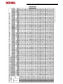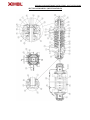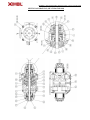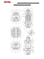
1
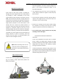
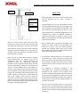
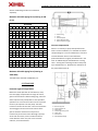
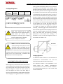
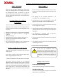
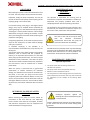
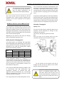
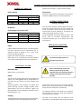
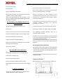
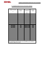
Pumping Solutions ASSEMBLY AND MAINTENANCE INSTRUCTIONS - MULTI-ROTOR PUMP INSTALLATION, OPERATION AND MAINTENANCE MANUAL MULTI-ROTOR PUMPS "ISO 9001:2008 Quality Management System Pumping Solutions Pumping Solutions ASSEMBLY AND MAINTENANCE INSTRUCTIONS - MULTI-ROTOR PUMP Dear Owner Congratulations! You have just acquired a simple piece of construction equipment, designed and manufactured with the most advanced technology, with excellent performance and easy maintenance. The purpose of this Manual is to provide the user with the equipment's details, and the correct Installation, Operation and Maintenance techniques. IMBIL recommends that the equipment is installed and cared for as recommended by the correct technique and in accordance with the instructions contained in this Manual, and that it is used in accordance with the service conditions for which it was selected (flow, Total Dynamic Head, speed, voltage, frequency and temperature). IMBIL is not liable for defects arising from the breach of these service prescriptions, and recommends that this Manual is used by the personnel responsible for installation, operation and maintenance. In the event of query about the equipment or when ordering spare parts, indicate the part's code, pump line and also the series no. found on the identification plate and recorded in low relief at the pump suction flange. NOTE: IMBIL asks that the customer, straight after receiving the GUARANTEE DOCUMENT for his/her equipment, fills in the data and sends the stub to IMBIL, facilitating the exchange of information between IMBIL and the CUSTOMER. ASSEMBLY AND MAINTENANCE INSTRUCTIONS - MULTI-ROTOR PUMP Pumping Solutions RECEIPT INSPECTION Upon receipt of the pump, inspect it carefully for damage and check it against the issue receipt. Report any damage or faults immediately to the local representative of the transporter and send a copy to IMBIL, which should be received in writing within one month from the receipt of the equipment. Inspect the protective layer of the various parts, and if necessary, apply further protection to the areas where it has already been torn. Inspect all painted surfaces. If necessary, retouch the areas where the paint may have chipped or scratched. Inspect all the lids on the discharge flanges and pipe connections for damage or clearance. If necessary, remove the lids and inspect the accessible inner areas visually for the accumulation of foreign materials or water. If necessary, clean and conserve the inner parts, as mentioned above, and replace the lids and tighten securely. NOTE: When unpacking, take care not to drop any boxes or packaging with accessories or spare parts that may be attached to the crate TRANSPORTATION Lift the entire unit using appropriate lifting techniques (Fig. A). Properly trained staff should perform the lifting in accordance with local regulations. The driver and pump weights are given in the General Arrangement design of the purchased equipment. The complete pump unit may not be swung when raised. Always introduce a support so that the pump does not turn. Ensure that the equipment used for lifting is able to support the weights found, and that the parts are completely secure before lifting. Remove the coupling and the spacer before lifting the complete unit. Always raise using the 4 lifting supports supplied at the base for lifting the unit. Do not lift the pump, engine and base from the pump and wing screw on the engine. To lift the driver: follow the manufacturer's instructions. To lift units assembled at the base with or without drivers: Attach the lifting straps through the lifting brackets provided at the base (Figure A) with a suitable lifting device for lifting the unit uniformly, without turning to one side or the other. To lift the pump only: Attach the lifting straps to the bearing blocks of the pump, passing through the cooling pipe. Raise the pump uniformly (without turning) with adequate lifting equipment (Fig. b). ASSEMBLY AND MAINTENANCE INSTRUCTIONS - MULTI-ROTOR PUMP Pumping Solutions STORAGE SHORT-TERM: When it is necessary to store the pump for a short period (less than six months) before its installation, place it on a pallet in a dry place away from vibrations. Protect it completely from moisture, sand, gravel or other contaminants. Do not remove the protective lids supplied with the suction and discharge flanges, and with the pipe connections. Turn the pump, rotating the shaft, in the direction of rotation, 2 ¼ turns every week to avoid seizure of the bearings and to prevent the seal faces sticking. To store the engine, follow the instructions of its manufacturer. When the pump is stored for more than six months. The pump must be covered or stored in a closed environment. Before storage, remove the plug from the oil passage and fill the bearing casing with a quarter of vapor-emitting oil. Replace the passage plug. Perform the procedure at 3-month intervals. Cover all external machined and unpainted surfaces generously with a light petroleum grease or equivalent anticorrosive oil. Remove the passage of the bearing block casing and drain plugs, and drain the oil. Replace the plug and fill the bearing block casing again with a quarter of vapor-emitting oil. Replace the passage plug. Turn the shaft of the pump 3 ½ turns (to remain at 180° from the original position). Remove the protective lids of the suction and discharge flanges. Remove any visible rust from the inner surfaces and cover with an anti-corrosive oil. Replace the protective flange lids. NOTE: Accumulation of condensation in the pump should be avoided. Store the equipment away from climactic extremes. Do not store the pump in areas with high environmental temperature variation, as this may cause damage to the bearing blocks. When auxiliary equipment such as drivers, mechanical seals, and instrumentation are provided, additional preparative measures may be necessary for long-term storage. See the manufacturers' literature for specific instructions. FOUNDATION A proper foundation and grouting can make the difference between a unit that generates many years of trouble free service, or one that requires constant realignment. It should therefore be the concern of all to ensure that only the best materials, as well as an adequate design, are used when performing this important function. NOTE: The foundation (4”to 6” longer and wider than the base) must be sufficiently rigid and substantial to absorb any vibration and to provide permanent support to the base. This is important for keeping the units aligned. A mortar foundation on a solid base should be satisfactory. The foundation screws must be installed as shown in (Figure 1), and should be placed in accordance with the certified design sent previously. LEVELLING THE UNIT Before the pump is placed on the foundation, wrench the leftover parts from the mortar, leveling the entire surface of the foundation, leaving it rough, but level. The surface should be free of oil, grease and loose particles, and material residue close to the foundation should be removed. ASSEMBLY AND MAINTENANCE INSTRUCTIONS - MULTI-ROTOR PUMP Pumping Solutions RESIDUE PROJECTION FOUNDATION ANCHOR: J Screw PIPE SLEEVE Clean the screws and the under part of the base, removing oil, grease, dust and other coverings that may affect the grounding or react with the cement. Check the base and the proposed mortar placement method to avoid the trapping of air on the base. Airventilation holes are placed on the platform of the base to help fill in any gaps. Place the unit on the foundation with the coupling halves disconnected. The coupling must not be reconnected until the leveling operations are complete. Follow the appropriate alignment procedure for your equipment after leveling. The base must be supported by rectangular metal blocks and shims or on metal wedges with a small reduction in thickness. These support pieces should be placed close to the foundation screws. Adjust the supports or metal wedges until the shafts of the pump and the driver are leveled. Check the leveling faces and the discharge and suction flanges of the pump to check the horizontal / vertical position using a level. Correct the positions if necessary, adjusting the supports on the base as indicated (See section on field installation of the Engine and coupling alignment). GROUTING Before grouting, check that the leveling of the base and the alignment of the shaft / coupling is complete. Once the alignment is correct, the foundation screws should be tightened uniformly, but not very tightly. The unit should then be cemented to the foundation. The base should be completely filled with water, oil and shrink-proof mortar. The following suggestions are not compulsory but should be followed, modified or rejected by the engineer or builder, as these, and not IMBIL, are responsible for the planning and execution procedures for the work. Build a wooden barrier around the foundation and saturate the upper surface of the foundation with water for at least six (6) hours before grouting. Remove the remaining water with a hose or cloths before placing the mortar. Remove the water from the anchor bolts with cloths or a siphon. The formation method depends on the selection by the builder of a mortar placement procedure that allows the rapid and complete filling of the spaces to be cemented, and which keeps the mortar in total contact with the under part of the base until it has hardened. The vibration of machines operating in the surrounding area is frequently transmitted to the foundation of the machine to be cemented. Such machines should be switched off until the mortar has reached its initial configuration, otherwise the drying may be affected. Observing the surface of the water in a basin placed on the base will indicate whether the vibrations are present. Mix the mortar continually while it is poured to remove the air and completely fill the cavities under the base up to the level of the holes for mortar. Check whether the mortar flows under the edges of the base uniformly. ASSEMBLY AND MAINTENANCE INSTRUCTIONS - MULTI-ROTOR PUMP Pumping Solutions After 48 hours, shims, wedges, and extender screws used for leveling the base should be removed, and the remaining cavities should be filled with mortar. Only once the mortar is hard (72 hours or more later), should the foundation screws be tightened and the pump and driver aligned. PIPING Never use the pump as a support for piping. Never force piping to remain in the place of the suction and discharge flanges. Ensure that the piping for hazardous liquids has the possibility of a pump discharge before its removal. Support and anchor the suction and discharge pipes independently, close to the pump, so that when the flange screws are tightened, the tension is not transmitted to the pump housing. The piping should be aligned with the flanges of the pump to prevent excessive loads to the nozzles and to avoid vibrations induced by the piping. If an expansion joint or non-rigid coupling is used, install an anchor between the fitting and the pump. The correct installation of the anchor will prevent excessive loads to the nozzles of the pump; It is good practice to increase the size of the suction and discharge pipes that lead to the nozzles of the pump. Arrange the piping with the lowest number of bends and fittings as possible. Use longer radius elbows when possible - see the Piping Diagram. All this results in a reduction in the load loss due to friction. Wash all piping carefully to remove any foreign material before connecting it to the pump. The thermal expansion of the piping should be compensated by appropriate devices so that no additional load is imposed on the pump, exceeding forces and moments. An excessive increase in the piping forces may cause leakage in the pump, where the pumped product may escape into the atmosphere. To avoid greater problems, expansion joints must be used. Danger to life when hot product is handled. FORCES AND MOMENTS IN PIPES Direction of forces: X = horizontal, parallel to pump shaft Y = vertical to pump shaft Z = horizontal, at a right angle to the pump shaft Direction of moments: Mx = around the horizontal axis, parallel to the pump shaft My = around the shaft of the vertical nozzle Mz = around the horizontal axis, at a right angle to the pump shaft ASSEMBLY AND MAINTENANCE INSTRUCTIONS - MULTI-ROTOR PUMP Pumping Solutions Suction and discharge nozzles are considered separately. Maximum allowable piping force (Housing at A48 CL 30) DN FLANGES 32 50 65 80 100 125 150 200 250 Vertical nozzle, at right angle to the shaft (N) Fx 245 510 640 700 1015 1470 1780 2700 - Fy 410 635 800 970 1270 1850 2220 3490 - Fz 265 415 520 625 - 830 1220 1465 2220 Horizontal nozzle, at right angle to the shaft (N) Fx 245 510 640 800 1015 1470 1780 2700 - Fy 265 415 520 625 1220 1465 2220 - Fz 410 635 800 970 1270 1850 2220 3490 - 830 Axial nozzle, parallel to the shaft (N) Fx - - 800 - 1270 1850 2220 3490 4760 Fy - - 520 - 830 Fz - - 640 - 1015 1470 1780 2700 3810 1220 1465 2220 3180 Moment for all nozzles (Nm) Mx 260 330 460 380 950 1235 1640 2520 3580 My 160 250 350 520 715 930 1260 1840 2710 Mz 190 170 240 340 490 660 840 1260 1740 1 2 3 4 5 – Sieve housing - Screen - Perforated plate - Suction flange of pump - Differential pressure gage Vacuum compensation When it is necessary to pump the liquid from the tank in vacuum conditions, it is advisable to install a compensating line. This line should have a minimum nominal diameter of 25 mm and should be positioned above the highest permitted level in the tank. An additional pipe assembled with a closing valve - starting at the discharge nozzle of the pump up to the balance line - facilitates the ventilation of the pump before start-up. Maximum allowable piping force (Housing at A216 WCB) The table values should be multiplied by 1.4. SUCTION PIPE Protection against foreign bodies Before the initial operation of new facilities, clean, level and apply compressed air through all vessels, pipes and connections. Often welding slag, scale and other impurities only escape after a short period of operation. Fit a sieve to the suction to line to prevent the entry of impurities into the pump. The total transversal section of the holes in the sieve should be 3 times bigger than the transversal section of the pipe to avoid the excessive loss of pressure transversally to the sieve due to blockage. Tapered sieves with wire mesh, 2mm in width and with a mesh diameter of 0.5 mm, with a rust-resistant material, are recommended. A – Main closing valve B – Vacuum balance line C – Closing valve E – Vacuum-tight closing valve R – Check valve V – Vacuum tank Z – Intermediary flange Pumping Solutions ASSEMBLY AND MAINTENANCE INSTRUCTIONS - MULTI-ROTOR PUMP The nominal diameter of the suction pipe should be greater than or equal to the nominal size of the pump suction. The suction pipe should be as short and straight as possible. Straight pipes of equal size five (5) times the diameter of the pipe should be connected to the suction flange of the pump to obtain a uniform flow at entry. Ensure that the suction lines are sealed and ventilated to avoid leakage and air bubbles. Reducers, if used, should be eccentric and installed with sloping side downwards to prevent the trapping of air. Reducers should have a maximum divergence angle of 15°. Never accelerate the pump with the suction valve closed and never place the valve directly against the entry nozzle of the pump. Where stents are used in the discharge, they must be positioned between the check valve and the pump; they should have a maximum divergence angle of 15° and (if located horizontally), must be installed with the sloping side down to prevent the trapping of air. SHAFT ALIGNMENT / COUPLING A reducer or elbow of the section pipe should be positioned at a distance of at least 5 (five) times the diameter of the pipe from the suction flange of the pump. For start-up, suction filters of the tapered type should be used, and there must be a net flow area of at least 3 (three) times the section area of the suction pipe. The suction reducer must be installed at a distance of 5 to 20 times the diameter of the pipe against the current from the suction flange. A cylindrical piece must be installed in the suction line to facilitate the installation and removal of the suction filter. Pressure gages must be installed on both sides of the filter to measure the pressure drop. An increase in differential pressure indicates that the filter screen is getting clogged. At this point, the pump should be turned off and the screen should be cleaned and replaced. When working under suction head or flooded suction, install a sectioning valve in the suction line to allow the closure of the line for inspection and maintenance of the pump. When the pumps and drivers are received from the factory with both machines assembled on a common base, they were carefully aligned before shipping. All bases are flexible to a certain extent, and, therefore, it should not be expected that they maintain factory alignment. Realignment is necessary once the complete unit has been leveled at the foundation, and again when the mortar has rested, when any final pressure grouting has been made, and once the foundation screws have been tightened. The final alignment of the pump with the engine should be checked once the unit has been connected to the piping and checked again periodically, as described. To facilitate precise alignment in the field, IMBIL does not secure bases and drivers to the bases before shipment. NOTE: The shafts must be aligned in all directions for successful operation. The above misalignment of the limits specified in this section may cause noise, vibration, excessive wear and damage to the equipment. Pumping Solutions ASSEMBLY AND MAINTENANCE INSTRUCTIONS - MULTI-ROTOR PUMP insert the screws and align the driver before tightening them. The following procedures are the same for the factory-aligned units. Ensure that the engine is switched off and locked before removing or installing the coupling or coupling guard. FLEXIBLE COUPLING Remove coupling guard and the coupling spacer (if required for your tooling). Check that the radial variation of the coupling measured between the edges of the flange is within the total radial variation of 0.005 inches (0.127 mm). Check that the faces of the coupling flange are parallel within the range of 0.003 inches (0.076 mm). NOTE: If the pump must operate above 300 °F (150 °C), it is important to align the pump at operation temperature. Consult your local IMBIL Service Center for support. The primary functions of all flexible couplings are: To transmit power from one shaft to another, efficiently and effectively. To accommodate small misalignments of the shaft that arise during activity. The secondary functions of flexible couplings are: To observe shock loads and pulsations. To minimize vibrations. DRIVER FIELD MOUNTING When the driver must be assembled on the base in field, it is necessary to please the base with the pump in the foundation, level the shaft of the pump, check the coupling faces, including parallelism and angular misalignment adjustments, and the suction and discharge flanges in relation to the vertical and horizontal positions, and to make any necessary corrective adjustments. The pads of the driver at the base can now be with chalk to facilitate the marking of the holes of the fixing screws. Position the driver on the base so that the distance between the two halves of the coupling is equal to that indicated in the diagram. Adjust the height of the driver, placing shims under the feet of the driver. Once the alignment of the coupling halves is correct, including parallelism and angular misalignment adjustments, perforate at the center with a transfer tool or mark the circumference of the screw holes at the base of the driver feet. Remove the driver, determine the size of the fixing screws, and drill at the base. Replace the driver at the base, To accommodate load reversions. To minimize initial setback. To ensure ease of installation and maintenance. To reduce wear in shaft bearings and equipment. The shafts become misaligned during operation due to the foundation, due to the effects of heat, vibration, worn bearings, etc. These misalignments occur in the form of angular misalignment, parallel misalignment, or axial movement of the shafts (fluctuation of extremities). Thus, to achieve the complete working life of any flexible coupling, it is necessary to (a) ensure the correct alignment of the shaft during initial installation, and (b) to check and correct, occasionally, the misalignments of the shaft in all directions during service. ASSEMBLY AND MAINTENANCE INSTRUCTIONS - MULTI-ROTOR PUMP Pumping Solutions Coupling Misalignment: PARALLEL MISALIGNMEN T REGULAR ANGULAR AND PARALLEL MISALIGNMENT ANGULAR MISALIGNMEN T FLUCTUATION OF EXTREMITIES AERIAL VIEW FRONT VIEW NOTE: Any coupling that is highly subjected to stress by torque will have a small reserve for stresses due to misalignment. Conversely, if the coupling receives a slight torque, it will have ation is greater than 0.05mm place a shim on the foot to the size of the deviation. "For example, if the deviation observed is 0.25mm, then this is the size of the shim to be placed on the foot. Tighten and repeat the procedure for all other feet. Spacer-type coupling is used between the pump and the driver. To align it, remove the spacer between the pump and the driver. Produce a support, as shown in (Figure 7), which may be connected to one of the halves of the coupling, and which is long enough to reach the other half. Connect this support to one half of the coupling and a dial gage to the support arm so that the gage comes into contact with the bar of the coupling half, as shown in "A", (Figure 7). Rotate one half of the coupling manually, so that the gage moves around the other half. Once the alignment of the coupling bar has been achieved, change the gage so that it leans against the face of the same half, and make any necessary adjustments. If the shafts have end-play, it is advisable to carry out this face alignment check in micrometers, as shown in "B". greater reserve for misalignment conditions. DIAL GAGE NOTA: It must also be advised that any coupling rotating at low speeds, as used in conjunction with the low-speed side of a gear reducer, may lead to relatively large misalignments in the long term. On the other hand, any coupling rotating at high speeds must be aligned with great care so as to ensure that a continuous and problem-free service will be provided. ALIGNMENT OF SPACER COUPLING Before alignment, check that the driver does not have overly soft feet, to ensure that there is no undue stress to the screws that secure the driver due to the base being non-aligned or rotated. To check, remove all shims and tighten the driver at the base. Begin to loosen a screw and measure the deviation of that foot with a dial gage or using depth indicators. “If the devi- Coupling Alignment: The Maximum radial variation in "A" should follow the manufacturer's recommendation and must not exceed the total radial variation of 0.127mm. The maximum variation in the parallelism in "B" should follow the coupling manufacturer's recommendation and must not exceed 0.0762mm. The recommended spacing up to the central shaft must be maintained. Pumping Solutions ASSEMBLY AND MAINTENANCE INSTRUCTIONS - MULTI-ROTOR PUMP NOTE: Couplings of the gearing type are aligned in the same way as shown in (Figure 7). However, the coupling lids must be moved backwards, away from the path, and the measurements made at the central shaft of the coupling. It is impossible to align any equipment perfectly. We therefore recommend that in the event of vertical misalignment you assemble the equipment with the greatest dimension between the base of the assembly foot and the central line of its shaft before mounting it on shims for alignment. Example: The shaft of an engine or gear mounted on one foot would be below the shaft of a pump mounted on the central line. When a turbine driver is used to drive the pump, this variation in the elevation of the shaft must be checked again once the driver has reached operation temperature. An approximate cold environment may be obtained from the manufacturer of the driver. FINAL ALIGNMENT CHECK Once the mortar has settled, and the pressure mortar for filling in the gaps has also settled, and the foundation screws have been tightened properly, the unit should be checked for parallel and angular alignment, and if necessary, corrective measures must be taken. The machinery must be free from tensions or distortions. Loosen and then tighten the fixing screws of the pump and the engine sequentially, using a dial gage in the coupling, in order to monitor and ensure that the units are supported uniformly. Once the piping of the unit has been connected, the alignment should be checked once again while tightening the connection screws. NOTE: The direction of the driver's rotation should be checked to make sure that it matches that of the pump. The coupling halves may then be re-connected. With the pump properly primed, the unit must then be operated under normal operating conditions until the temperatures have stabilized. The unit should then be switched off and immediately checked again in relation to the coupling alignment. It must be emphasized that attempts to correct the alignment in one direction may alter the alignment in the other direction. As such, it is necessary to check in all directions having made the adjustments. Pumps must have a level of 0.127mm per foot at the operating temperature when measured at the extension of the shaft. SHIMS Shafts must be clean and dry. Water, dust and rust may affect the height of the shim after a certain time. The shims must be large enough to support the weight of the equipment on its assembly foot. Use a combination of thick and thin shims (set of maximum of 5) on the foot to compensate the misalignment, instead of using several thin shims, which may result in spongy assembly. The equipment must be moved vertically to add or Remove shims. Torque of screws, consult page 28. NOTE: “Shims added at the factory may be stacked up to a minimum of 1/8” (3 mm) and a maximum of 1/4"; ASSEMBLY AND MAINTENANCE INSTRUCTIONS - MULTI-ROTOR PUMP Pumping Solutions FIXING WITH PINS Once the unit has been operating for around one week, the coupling halves must undergo a final check for misalignment caused by tensions in pipes or tensions caused by temperatures. If the alignment is correct, the pump and the driver must be fixed at the base with pins. FACTORS THAT MAY AFFECT ALIGNMENT The unit must be checked periodically in terms of alignment. If the unit does not remain aligned once it has been properly installed, the following factors may be causes: Settlement, adjustment or removal of the foundation. Tensions in the pipes that distort or change the machine. Wear to bearings. Raising of base due to heat or adjacent steam pipe, etc. Chance to constructed structure due to variable loads or other causes. For a new unit and foundation, it may be necessary to readjust the alignment slightly from time to time. FIRST START-UP Before starting the operation of the pump, confirm whether the following requirements have been met correctly: The quality of the concrete foundation is in accordance with the Regulation in force. The fixing of the set to the foundation, shims and alignment corresponds to the stipulated margins. The pipes have been connected without distortion to the flanges of the pump. The electrical connection and adjustment of the timer correspond to the power of the engine and applicable regulations. The equipment is equipped with all hydraulic, electrical and mechanical protections. The pump has been totally primed with the product to be pumped. The rotation direction of the unit corresponds to that indicated by the arrow. All connections have been tightened. INITIAL OPERATION/ SHUTDOWN Additional information for operation with the boiler supply pump. Limit values for boiler and condensed supply water when using pump parts in cast iron: In the case of installations with no foundation (for example anti-vibratory), it must be ensured that all movements of the set may be balanced (e.g. through the installation of compensatory elements) in the suction line as in the holding pressure line. - pH> 9.0 (suitable value > 9.3).O content < 0.02 ppm. The values must be ensured for any operating conditions before entering into the pump. The fresh water part must be 25% at most. Water treatments must be in accordance with national regulations for boiler supply water in steam plants up to 64 bar. The penetration of air into the system must be avoided at all costs. LUBRICATING AGENT Grease-lubricated bearings Grease-lubricated bearings are filled at the factory. Oil-lubricated bearings The lids of the bearing block supports are filled with HD20-quality oil (ISO VG46). Pumping Solutions ASSEMBLY AND MAINTENANCE INSTRUCTIONS - MULTI-ROTOR PUMP PUMP PRIMING AND CHECKS CONNECTION TO POWER SUPPLY Before each start-up, the pump and suction line must be completely primed with the liquid to be pumped. The pump has several plugs, made for the elimination of air. Similar air elimination devices may be used in pipes. The blocking elements in the suction line and supply line must be completely open. Open all auxiliary connections completely and check the flow. Open the closure valve on the vacuum compensating line (if there is one), close the valve, vacuum-tight. If the pump is equipped with an electric engine, the connection to the power supply must only be made by a trained electrician. The voltage available on the network must be compared with the indications on the plate of the engine and the type of start-up chosen. Check that the three-phase motors with star-delta starting will be started from star to delta at short intervals. Extended intervals may result in damage to the pump. Dry operation will cause increased wear to the unit and may damage the pump! Adjustment of timer relay for star-delta starting. Power of Engine < 30 kW > 30 kW If the discharge line is equipped with an automatic check valve, open the minimum flow valve, and ensure against unforeseen closure. Time Y to be Adjusted 3 seconds + 30% 5 seconds + 30% START-UP Exceptions: Start-up procedure: If there is no contra-pressure before start-up, the lock valve of the pressure line must be closed. In pumps assembled with a mechanical seal, the mechanical seal will have negligible or invisible leaks (in vapor form) during operation. The seal is maintenancefree. If the pump is equipped with a gasket, the leakage during start-up is normal. If the pump is equipped with a refrigerated mechanical seal, ventilate the sealing chamber by unscrewing the ventilation plug by a quarter of a turn and re-tighten. CONTACT PROTECTION In agreement with the accident prevention regulation, the pump must not be operated without a coupling guard. If the customer specifically requests the noninclusion of a coupling guard in its order, then the customer is liable. The blocking valve on the discharge side must be closed. The start-up must proceed without vibrations or noise. When the operating speed has been reached, an automatic check valve needs to open, without abnormal noise, vibrations or increase in power consumption. Open the blocking valve on the discharge side. Once the operating point has been reached, check the absorbed power of the engine and the bearing block temperature. Once the operating temperature has been reached, switch off the unit and tighten the screws of the flanges. In the event of abnormal noise, vibrations, temperatures or leakage, switch off the unit immediately and only restart once the cause of the problem has been eliminated. abnormal ASSEMBLY AND MAINTENANCE INSTRUCTIONS - MULTI-ROTOR PUMP Pumping Solutions the pump's operation. High bearing temperatures after first startup are attributable to initial reactions. The definitive temperature of the bearings is only established after a certain operating time (depending on the conditions in up to 48 hours). STOPPING Close the blocking valve on the discharge line. If the discharge line is equipped with a check valve, the blocking valve may remain open, provided that there is sufficient contra-pressure in the line. Switch off the driver, checking that the pump is stopping smoothly. In the event of prolonged switching off, the blocking valve of the suction line must be closed. Also close any blocking element in the auxiliary lines. The pump sealing system, in which the liquid flows in a vacuum, must be supplied with sealing fluid throughout the stopping period. In the event of extended stopping, the pump must be drained or protected against freezing. If the pump must remain operational throughout stopping periods, it must be switched on regularly for at least 5 minutes. Fire-extinguishing pumps at least once a month. Pump for drinking water at least once every 48 hours Reserve pump at least once a week. (The best option is to alternate daily with the pump in operation). The function and tightness of auxiliary lines should be checked during these pump stops. FINAL CHECK Once the pump has been prepared, it should be easy to turn the coupling by hand. Leaks in the sealing system are unacceptable during Packing The gasket is assembled at the factory. Its ideal compression may only be adjusted after hours of the pump's operation. Throughout this operation period, the leakage will be greater than during the normal operation period of the pump. Check the temperature of the fluid in the leak. The final adjustment of the gasket is made gradually after a sufficient operation period, so that the leakage is reduced to a drip (around 20 drops per minute). Tightening the gasket very early, or too strongly without allowing a sufficient operation period, will lead to an increase in the local temperature and insufficient lubrication, resulting in the destruction of the gasket, premature wear of the protective sleeve of the shaft and uncontrollable leakage. It is not recommended to use a gasket for pumps with adjustable rotation or with variable inflow pressure. Variable pressures make adjustment to a uniform and controllable drip difficult. Once these conditions are confirmed, the increased dripping cannot be prevented. With the suction pressure increased and / or the rotation (RPM) increased, the increase in the leakage of the gasket occurs forcibly. It cannot be reduced by tightening the gasket tightening screws. Regulation to a minimal drip can only be made with the pump in rotation and / or with a lower suction pressure. MECHANICAL SEAL The mechanical seal set is adjusted and installed at the factory. It does not require maintenance. Check the seal for leakage occasionally. During the initial start-up, an increase in leakage may occur for a short period of time. If the leakage continues to be great, stop the unit immediately and check the cause of the leakage, for example: contaminated pumped product, or previous start-up dry due to incomplete purging of air. Refrigerated Mechanical Seal If the pump is equipped with a refrigerated mechanical seal, ventilate the sealing chamber as described. ASSEMBLY AND MAINTENANCE INSTRUCTIONS - MULTI-ROTOR PUMP Pumping Solutions OPERATING LIMITS The pump is suitable for working with pure or slightly contaminated fluids (max solid content of 20 ppm). It is essential to ensure that the operating limits indicated when confirming the request are maintained. TEMPERATURE OF PUMPED PRODUCT Do not operate the pump at temperatures above those specified on the identification plate or in the technical data. t -10 to +100 °C t >100 to +140 °C t >140 to +200 °C 15% of BEP 20% of BEP 25% of BEP In isolated incidents that require a precise calculation, contact IMBIL. The minimum flows cited above are valid for the operation of an independent pump and prevent an excessive thermal or mechanical stress. In the case of operation of a pump in parallel with identical pumps or other pumps, greater minimum flows may be partially necessary to ensure a secure behavior and operation. DENSITY OF PUMPED PRODUCT START-UP FREQUENCY The number of start-ups allowed in a given period of time depends upon the installation circumstances and operation conditions. The overloading of the engine may result in: The power consumed by the pump will increase in proportion to the density of the pumped product. To avoid the overloading of the engine and the pump, the density of the pumped product must comply with the data specified in the purchase order. Abnormal increase in temperature, exceeding the limit values of the bearings and the grease of the bearing blocks. STOPPING / STOCKING / PRESERVATION The Pump / Unit Remains Installed Premature wear of the coupling. Periodic Operation Check Reduced working life of the pump components. To confirm that the pump is already ready to operate and to prevent the formation of deposits within the pump and pump inlet area, switch the pump set on regularly, once a month or once every three months for a short period (approximately 5 minutes). To do this follow the instructions for the first start-up. For pumps manufactured in cast iron, prolonged stopping times must be avoided, especially for aggressive water pumps (high oxygen content). In this case, the pump must remain filled and it must be made to operate for at least 2 days every 1 to 3 months. Irregularities or damage in installation. To avoid abnormal temperature increases to the engine and excessive load to the coupling, pump, seals and bearing blocks, the frequency of start-ups must not exceed the following number of start-ups per hour. Engine Power up to 3 kW (4 Hp) 4 to 11 kW (4 to 15 Hp) 11 to 45 kW (15 to 60 Hp) above 45 kW (60 Hp) Max. no. of start-ups/h 20 15 10 5 MINIMUM FLOWS If the type of operation allows the operation of the pump against a blocking valve on the closed discharge side, the following minimum flows are required throughout this time. In the event of freezing and/or extended stopping, the pump needs to be drained and protected against freezing and rust. To empty the pump, open the plug. A complete emptying of the stages with horizontal pumps is only possible when opening the plugs in stages (special design). When this is not possible, it is recommended to decouple the pump from the engine and to proceed in accordance with chapter 6.3.2. THE PUMP IS REMOVED FROM THE INSTALLATION ASSEMBLY AND MAINTENANCE INSTRUCTIONS - MULTI-ROTOR PUMP Pumping Solutions AND STORED Before storing the pump, a review and maintenance must be made. Then the pump must be preserved as follows. If possible, empty the pump completely. This may be carried out with vertical pumps via the opening of the emptying plugs in the suction body. In horizontal pumps, with plugs in the stages (special design), they may be emptied almost completely by opening the plugs. It is also possible to empty the pump via lifting to a vertical position with the suction flange downwards, turning the rotating set manually. In spite of this, the sealing box must me drained by opening the respective closing plug. Using lifting equipment, ensure that the pump cannot slip from the suspension, to avoid material damage and injury to persons. If complete emptying is not possible, it is recommended to disassemble the pump and dry the loose parts. Then fill the pump with a water-resistant conservation substance, such as Rustilo DW 301 (supplied by Castrol), or an equivalent preservative. Turn the shaft of the pump by hand several times, to ensure an equal distribution of the preservative. Then drain the pump and close the nozzles. Polished metal parts, exposed to the environment, must be treated with a suitable preservative. When the pump is preserved with a glycol-based preservative, or another substance, for extended storage, the substance used cannot be removed from the pump. In this case, the pump must be stored completely full of this substances. Before re-entry into service, the preservative must be drained and may be used again. Before the next use, ensure that the water content in the preservation substance does not exceed 20%. RETURNING TO SERVICE AFTER STORAGE Before returning the pump to service, follow all instructions of the "First start-up" and "Operating Limits" sections. Once the work is complete, all safety and protection equipment must be readjusted and reactivated before starting the pump. MAINTENANCE AND GENERAL INSTRUCTIONS The operator is responsible for ensuring that all maintenance, inspection and installation is made by an authorized and properly qualified team that is completely familiar with the operating instructions. The preparation of a maintenance plan will allow, with minimal cost, the avoidance of expensive repairs and will ensure a safe, malfunction-free operation. The work to the unit must only be made with the electrical connections disconnected. Check that the pump set cannot be switched on accidentally. Harmful fluids to be pumped, which may cause damage to health, must be decontaminated. When the product is drained, check that there are no risks to people or the environment. All relevant laws must be considered. MAINTENANCE / INSPECTION Operation Supervision The pump must operate silently and free of vibrations at all times. The pump must never be operated when dry. Maximum room temperature 40 °C The temperature of the bearing block may exceed the room temperature up to 50 °C, but may never exceed 90 °C, (measured on the outside of the bearing block support). Prolonged operation against the blocking valve of the closed delivery pipe is not permitted. Caution: Minimum flow required. The locking element in the suction line must not be closed during pump operation. ASSEMBLY AND MAINTENANCE INSTRUCTIONS - MULTI-ROTOR PUMP Pumping Solutions The mechanical seal only leaks slightly or invisibly (vapor) during operation. It does not require maintenance. The gasket should leak slightly (dripping). Any reserve pumps must be switched on and off immediately once a week to keep in operation. Pay attention to the correct operation of the auxiliary connections. BEARING BLOCKS AND LUBRICATIONS To re-lubricate the bearing blocks of the pump with grease. Multi-rotor pumps 30 to 200 require the use of grease pins available, and for the outer rolling of the coupling side bearing block in sizes 50, 65, 100, 125, 150 and 200, the lid of the bearing block must be removed and it must be filled with grease. Depending on the version of the pump, the bearing blocks are lubricated with grease or oil. resin and acid and not subject to disintegration, and with good rust-preventing characteristics. The grease must have a penetration number between 2 and 3, corresponding to the work penetration between 220 and 295 mm/10. Its dropping point cannot be below 175 C. If required, the bearing blocks must be lubricated with greases of other bases. As greases with different bases must not be mixed, the bearing blocks must be totally cleaned before re-lubrication. The lubrication interval required must then be adjusted to the greases used. Oil Quality / Changing Oil Quality: HD20 The first oil change must be made after 300 hours of operation, and all subsequent oil changes at every 3,000 hours of operation. Unscrew the drainage plug. Remove the filler plug. Once the body of the bearing block has been completely drained, close the drain hole again. Quality of grease / Changing grease The bearing blocks are assembled with high-quality lithium soap-based grease. Depending on the size of the pump, operation time (hours), the bearings should be lubricated or the inside the bearing block support greased, and the bearing replaced. Size 32 - 50 - 65 100 - 125 150 Rotation (RPM) < 1800 ~ 2950 10,000 h 7,200 h 9,000 h 5,700 h 8,300 h 4,000 h ~ 3550 5,700 h 3,900 h 3,100 h If the lubrication interval is < 4,000 h, it is recommended to change the grease completely once a year. If this is not the case, the complete grease change must be made at least twice a year, at which time the bearings are disassembled, cleaned, and lubricated with new grease. In the event of unfavorable operating conditions, that is, environments with high temperature, high atmospheric humidity, air polluted with dust, aggressive industrial atmosphere, etc., the bearings must be controlled earlier and, if necessary, cleaned and lubricated with new grease. Use a high quality lithium soap-based grease, free of Tilt the constant oil level reservoir. Flow the oil through the hole until the oil appears at the vertical position of the connection elbow. Then fill the constant oil level reservoir and return it to operation position. After a short time, check if the oil level in the reservoir has decreased. It is important to keep the reservoir 2/3 full with oil at all times. ASSEMBLY AND MAINTENANCE INSTRUCTIONS - MULTI-ROTOR PUMP Pumping Solutions LUBRICANT AMOUNTS Disassembly Grease Amount Pump Size Amount per bearing block (g) driving side opposite side 80 100 220 220 900 900 50 100 200 Oil Amount (considering 2/3 of reservoir full) Pump Size Amount per bearing block (ml) driving side opposite side 300 300 300 300 365 380 50 100 200 alignment of the engine - pump must be checked. Should you require further information or instructions, contact the IMBIL customer services department. GENERAL INSTRUCTIONS Drainage / Washing If the pump was used for pumping liquids that pose a health risk, ensure that there is no risk to people and to the environment when draining the product. All relevant laws must be adhered to. If required, use safety clothing and protection masks. The washing liquid used and any liquid residue in the pump must be collected appropriately and eliminated without any risk to people and to the environment. PREPARATION FOR PUMP DISASSEMBLY Engine Engines without lubrication points: The bearing block has been lubricated by the manufacturer for an operation period of 15,000 or for 2 years, under normal operating conditions. Engines with lubrication points: The bearing block needs to be re-lubricated at intervals indicated on the engine plate (approximately every 500 hours). Use the disassembly sequence as described in this manual. SHAFT SEAL SYSTEM Mechanical Seal Maintenance is not required. Gasket The nuts of the packing gland must only be tightened slightly. The packing gland must be perpendicular to the shaft once the pump has been prepared and before starting operation, check whether the gasket was placed allowing a greater leakage quantity. After approximately one hour of operation, tighten the gasket gradually until the leakage is reduced to a drip (approximately 7 l / h). Coupling The flexible elements of the coupling must be replaced in a timely fashion when they display signs of wear and Before disassembling, measure the distance from the tip of the shaft (opposite side) to the bearing locking nut. Leaving at the same dimension when assembly. Check that the pump set has been switched off before beginning any disassembly activity. Ensure that the pump cannot be switched on accidentally! The blocking elements in the suction line / elevation and discharge line must be closed and inadvertent opening must be prevented. The body of the pump must be cooled to room temperature. It must be drained and its pressure must be Pumping Solutions ASSEMBLY AND MAINTENANCE INSTRUCTIONS - MULTI-ROTOR PUMP released. Harmful, explosive and hot elements, and other hazardous elements must be drained without posing risk to people or the environment. Drying and cleaning the pump are an absolute necessity before sending the pump to the workshop. Important: Using a caliper, measure the distance from the tip of the shaft to the side of the bearing nut. This is necessary to ensure the same positioning of the rotating set (axial adjustment). Loosen the Nut with the safety ring. After an extended period of operation, components may present a difficulty in removal. some We recommend the use of a quality anti-grip agent or an appropriate extraction device. Do not force under any circumstances. Disassembly must always be executed observing the sectional drawings at the end of this service manual. Remove the Bearing block casing. It should come off together with the bearing, bearing bushing, centrifuge ring and retainer. Disassemble the centrifuge ring and the bearing bushing. Remove the retainer. SEAL SYSTEM DISASSEMBLY Heavy components must be sufficiently supported during disassembly. Components must be marked with their disassembly sequence, to ensure that they will be removed in the correct sequence. Completely clean the disassembled components and inspect their conditions. A careful check may help to find the cause of the pump fault, if there is one. If in doubt, replace the components. Always replace the parts subject to wear (gasket, O-ring, wear ring, bearing). DISCONNECTING AUXILIARY PIPES Disconnect auxiliary cooling pipe from the sealing system. Mechanical Seal Loosen the nuts and remove the stud bolts of the gland. Remove the mechanical seal. Gasket Loosen the nuts and remove the stud bolts from the packing gland. Remove the gaskets and the centrifuge ring. DISASSEMBLY OF HYDRAULIC ELEMENTS Following disassembly of the sealing system, proceed with the following steps: Disconnect balancing pipe from the axial thrust. Remove the protective sleeve from the opposite side. DISASSEMBLY OF BEARING BLOCK ON OPPOSITE SIDE Remove the nuts and the washers from the pull rods. Remove the Suction Housing. If the pump is lubricated with oil, drain the reservoir of oil before disassembling the bearing blocks. Remove the key from the protective sleeve. Remove the spacing bushing. Remove the screws and remove the Bearing block lid from the opposite side. Disassemble the other components in the following sequence: Pumping Solutions ASSEMBLY AND MAINTENANCE INSTRUCTIONS - MULTI-ROTOR PUMP Remove the pull rods. Do not force under any circumstances. Remove Rotor. Remove Stage body with Diffuser. Remove key from Rotor to release the removal of the next Rotor. Disassemble all stages. When removing the Body of the last stage, it must come out together with the Balancing bushing. Remove key from the last stage. DISASSEMBLY OF BEARING BLOCK ON DRIVING SIDE Due to their weight, some components of the pump must be supported during re-assembly. Before re-assembly, the local surfaces of the individual components must be re-covered with a protective oil, in accordance with hygiene / health and safety standards. The properties of the new components must not be changed without consulting our technical department in advance. Remove coupling from the tip of the shaft. The parts must be clean and free of chips and dirt. Remove key. reassembly is made in the reverse order of assembly. Loosen the screws and remove the Lid from the bearing block. The tightening torques indicated must be in accordance with the table. Remove the locking nut together with the locking washer. Remove the Washer from the bearing. Unfix the screws from the Bearing block. Remove the bearings from the bearing block and the bushing from the bearings. Remove the retainer. DISASSEMBLY FINALIZATION Disassemble the sealing system as described above. Remove the centrifuge ring. Avoid the use of chemical adhesives as far as possible. If it is really necessary to use them, give preference to commercially available products. Chemical adhesives must be applied at selected points and in thin layers. Do not use quick-sticking chemical adhesives. Re-assembly of the Hydraulic Set Re-assembly of the pump begins on the discharge side, starting with the mounting of the thrust ring onto the shaft, and then assembly must be followed in reverse order to disassembly. Tightening torques for pull rods and nuts are found in the table on page Remove the protective sleeve. Sea ling of Gasket Shaft Remove the Shaft outside the delivery casing. Disassemble the balancing sleeve, the key and the thrust ring. PUMP RE-ASSEMBLY The pump must be re-assembled in accordance with suitable engineering criteria, as follows: Before assembly, completely clean the gasket box ASSEMBLY AND MAINTENANCE INSTRUCTIONS - MULTI-ROTOR PUMP Pumping Solutions and the packing gland. Mechanical seals are precision components. The stationary ring and the rotating ring should always be replaced together, that is, always replace the complete mechanical seal. The gland rings must be inserted so that the join of the two ends is placed out of phase by 90 ° to 120 ° relative to the former. Place the gasket ring already preformed on the protective sleeve of the shaft, with the aid of the packing gland. Each ring must be pushed on to the gasket box individually, using the packing gland. In the case of packing with a lock ring (pumping in vacuum) this ring must be assembled in place of the penultimate gasket (the last gasket ring is within the sealing box next to the pump). The gasket must be tightened manually. Use a gage to control the correct position of the packing gland. It must be easy to turn the rotating set by hand. Leakage is normal during initial operation and may be reduced after 5 minutes of operation. The leakage amount may be reduced constantly by using the two nuts of the packing gland, turning them 1/6 of a turn each time. Then observe the leakage and monitor the water temperature. The definitive positioning only occurs after a few hours of operation. In this time, there must be a greater leakage. Repeat this procedure at 5-minute intervals to obtain a minimal leakage. Measurements in mm Section of the gasket Gasket cut length Gasket Amount 50 Pump Size 100 200 1/2" 1/2" 3/4" 181 mm 228 mm 373 mm 4 4 5 Sealing box The basic dimensions of the sealing boxes of Multirotor pumps are given in the table. Mechanical Seals Extreme care and cleaning during assembly are of the utmost importance with operations without mechanical seal problems. The faces of the seal must only be cleaned immediately after the set has been assembled. They must not be dirty (grease, fingerprints) or damaged. Pump Size Ø Ø box L sleeve 50 45 70.6 65 100 60 85.5 85 200 100 138.2 120 The individual components of the seal such as the Oring made of EPDM must never enter into contact with oil or grease. The mechanical seal must be reassembled in the reverse order of disassembly. Once the rotating ring is assembled, the shaft sleeve may be moistened with clean pumped material to reduce friction forces. The stationary ring and the rotating ring must always be assembled manually, ensuring that the pressure is applied uniformly, without binding. Static sealing elements Sealing elements made of EPDM must never into contact with oil and grease. Faulty O-rings (that have undergone mechanical damage such as cuts, cracks and deformations as well as changes due to layering or becoming brittle) must be replaced. New flat joints must be used when the pump is reformed. If possible, sealing elements must be assembled without the use of assembly protectives such as grease or adhesives, unless authorized protectives are being used. Leakage in mechanical seal Check the axial alignment of the seal Check the flat joint Remove the gland and position the stationary ring on the grand Check the O-ring of the shaft sleeve ASSEMBLY AND MAINTENANCE INSTRUCTIONS - MULTI-ROTOR PUMP Pumping Solutions BEARING BLOCKS Bearing blocks Bearing blocks are always mounted on a sleeve of the shaft and tightened with the shaft nut. Re-assembly is carried out in reverse order of disassembly. Both in grease lubrication and oil lubrication, the Bearing Block Casings are the same. Important: aim to keep the bearing nut (opposite side / free bearing block), as it was before disassembly. To do this, leave the same distance found before disassembly. The shaft nuts must be tightened in accordance with the torque table on page If an appropriate wrench is not available for applying torque to the shaft nut, proceed as follows: Self-locking nut on driving side and opposite side Tighten the nut firmly. Loosen the nut again. Apply safety agent to the thread of the screw (for example. Loctite). Tighten the nut slightly. Locking ring nut on driving side and opposite side Tighten the first nut firmly. Loosen the nut again. Tighten the nut slightly. Fold the tab of the locking ring. Self-locking nut on driving side and opposite side Tighten the nut firmly. Loosen the nut again. Tighten the nut slightly. Lock this nut with a suitable tool and tighten the lock nut firmly. Fixed bearing block The fixed bearing block is on the driving side. It is fitted with angular contact ball bearings to support the axial load. The bearings are the same both in grease lubrication and in oil lubrication. Free bearing block The free bearing block is on the side opposite the driving side. It is fitted with hard ball bearings. These bearings must have axial clearances. Bearing sizes The size of the bearings are provided in the following table: Pump Size 50 100 200 Fixed Bearing Block 2 x 7309 B 2 x 7312 B 2 x 7319 B Free Bearing Block 6309 C3 6312 C3 6319 C3 TEMPERATURE OF BEARING BLOCKS The temperature of the bearing blocks, which operate at 3,000 RPM or more can easily reach 90 °C. Manual temperature checks are not enough! The bearing blocks only reach their regular temperature after a few hours of operation. When a new pump is actioned, the temperature of the bearing block can exceed 95° C. After 2 or 3 hours of operation, it will slowly decrease and will return to normal after approximately one week. An increase in temperature may occur following activities (replacement of bearing blocks or disassembly of hydraulic system). If the temperature exceeds 100 °C at the beginning of the pump's operation, switch it off and make the following checks: Check that the set is correctly aligned. Remove the bearing blocks, check the quantity of grease. An excessive quantity of grease will cause excessive temperatures. Check the type of bearing block and arrangements. Restart the pump. Make sure that the bearing block lid is tightening the outer rings of the thrust bearings (fixed bearing block). Standard clearances for diameter of wear rings are as per the appendix. Pumping Solutions ASSEMBLY AND MAINTENANCE INSTRUCTIONS - MULTI-ROTOR PUMP ASSEMBLY AND MAINTENANCE INSTRUCTIONS - MULTI-ROTOR PUMP Pumping Solutions STANDARD MINIMUM CLEARANCES FOR WEAR RINGS Diameter of rotating member in clearance Minimum diametrical distance Diameter of rotating member in clearance mm inches Minimum diametrical distance mm inches <50 0.25 < 2.000 0.010 50 to 0.28 2.000 to 2.499 0.011 64.99 65 to 0.30 2.500 to 2,999 0.012 79.99 80 to 0.33 3.000 to 3.499 0.013 89.99 90 to 0.35 3,500 to 3.999 0.014 10099.99 to 114.99 0.38 4.000 to 4.499 0.012 115 to 124.99 0.40 4.500 to 4.999 0.016 125 to 149.99 0.43 5.000 to 5.999 0.017 150 to 174.99 0.45 6.000 to 6.999 0.018 175 to 199.99 0.48 7.000 to 7.999 0.019 200 to 224.99 0.50 8.000 to 8.999 0.020 225 to 249.99 0.53 9.000 to 9.999 0.021 250 to 274.99 0.55 10.000 to 10.999 0.022 275 to 299.99 0.58 11.000 to 11.999 0.023 300 to 324.99 0.60 12.000 to 12.999 0.024 325 to 349.99 0.63 13.000 to 13.999 0.025 350 to 374.99 0.65 14.000 to 14.999 0.026 375 to 399.99 0.68 15.000 to 15.999 0.027 400 to 424.99 0.70 16.000 to 16.999 0.028 425 to 449.99 0.73 17.000 to 17.999 0.029 450 to 474.99 0.75 18.000 to 18.999 0.030 475 to 499.99 0.78 19.000 to 19.999 0.031 500 to 524.99 0.80 20.000 to 20.999 0.032 525 to 549.99 0.83 21.000 to 21.999 0.033 550 to 574.99 0.85 22.000 to 22.999 0.034 575 to 599.99 0.88 23.000 to 23.999 0.035 600 to 624.99 0.90 24.000 to 24.999 0.036 625 to 649.99 0.95 25.000 to 25.999 0.037 For diameters greater than 649.99 mm (25.99 inches), the minimum diametrical distances will be 0.95 millimeters (0.037 inches) plus 1 for every additional 1 mm of diameter or fraction (0.001 in addition for every Inch). Pumping Solutions ASSEMBLY AND MAINTENANCE INSTRUCTIONS - MULTI-ROTOR PUMP TORQUE TABLE Pumping solutions ASSEMBLY AND MAINTENANCE INSTRUCTIONS - MULTI-ROTOR PUMP SECTIONAL DRAWING (MULTI-ROTOR 50) Pumping Solutions ASSEMBLY AND MAINTENANCE INSTRUCTIONS - MULTI-ROTOR PUMP LIST OF PARTS (MULTI-ROTOR 50) ITEM 1 2 3 4 5 6 7 8 9 10 11 12 13 14 15 16 17 18 19 20 21 22 23 24 25 26 27 28 29 30 31 32 33 34 35 36 37 38 39 40 41 42 43 44 45 46 47 48 49 MULTI-ROTOR 50 PUMP DESCRIPTION CENTRIFUGE RING PRESSURE HOUSING SUCTION HOUSING SUCTION ROTOR SERIES ROTOR END-STAGE DIFFUSER BALANCING BUSHING BALANCING SLEEVE BEARING BLOCK DRIVE OPPOSITE SIDE BEARING BLOCK DRIVE BEARING BLOCK LID OPPOSITE BEARING BLOCK LID SUCTION WEAR RING OPPOSITE SIDE SPACER BUSHING DRIVE GUARD BUSHING OPPOSITE SIDE PROTECTIVE BUSHING SHAFT END-STAGE ROTOR DRIVING SIDE BEARING BUSHING OPPOSITE SIDE BEARING BUSHING THRUST RING STAGE BODY DIFFUSER WEAR RING BODY OF LAST STAGE AXIAL BEARING WASHER PRESSURE WASHER M10 PRESSURE WASHER M12 LOCKING WASHER (WITH INNER CURVE TAB) MB 7 (35MM) HEX CAP SCREW (TOTAL THREAD) NBR 11207 M10X1.5X30 HEX CAP SCREW (TOTAL THREAD) NBR 11207 M12X1.75X40 DIN 934 HEX NUT M10X1.5 6309U BEARING C3 3/8" PIPE D.E. X 1.24MM WALL SQUARE HEAD PLUG 1/8" NPT M10 MILIMETRIC SERIES FLAT WASHER KM 7 FIXING NUT (M35X1.5) NBR 6925 SQUARE HEAD PLUG 1/4" NPT MILIMETRIC SERIES FLAT WASHER M12 SPECIAL STUD BOLT M10X1.5X65X10X40 NBR 6943 SQUARE HEAD PLUG 3/8" BSP 11.106 O'RING FPM VITON VEDABRAS (2.60X35.00) 7309B BEARING FOR ASSEMBLY OF PAIRS (REF.NSK) 11.585 O'RING (FPM-VITON) VEDABRAS (3.53X228.19) 11.597 O'RING (FPM-VITON) VEDABRAS (3.53X253.59) PULL ROD WASHER 31,832 RETAINER R-5 (FPM-VITON) VEDABRAS (45X65X8) 33,274 RETAINER R-5 (FPM-VITON) VEDABRAS (29.5X43X8) PULL ROD M20X1.5 QTY UNIT 2 PC 1 PC 1 PC 1 PC 9 PC 1 PC 1 PC 1 PC 1 PC 1 PC 1 PC 1 PC 1 PC 1 PC 1 PC 1 PC 1 PC 1 PC 1 PC 1 PC 1 PC 8 PC 9 PC 9 PC 1 PC 1 PC 8 PC 8 PC 2 PC 8 PC 8 PC 8 PC 1 PC 3 mm 3 PC 16 PC 1 PC 5 PC 8 PC 8 PC 3 PC 3 PC 2 PC 9 PC 1 PC 8 PC 2 PC 1 PC 8 PC Pumping Solutions 50 51 52 53 54 55 56 57 58 59 60 61 ASSEMBLY AND MAINTENANCE INSTRUCTIONS - MULTI-ROTOR PUMP FLAT-HEAD INTERNAL SOCKET SCREW M6X20 HEAVY HEX NUT M20X1.5 SPECIAL KEY 8X7X61 TYPE C SPECIAL KEY 10X8X20 TYPE B SPECIAL KEY 10X8X35 TYPE B 438 FLAT JOIN (160X102X0.80) JOIN CONNECTOR TUBE X TUBE X TUBE 3/8" D.E. DOUBLE WASHER 5-CONNECTOR TUBE X TUBE X TUBE 3/8" D.E. DOUBLE WASHER MALE CONNECTOR TUBE 3/8 D.E. "X MALE THREAD 1/4" NPT DOUBLE WASHER NEEDLE VALVE - CL3000 LBS - 1/4" NPT X 1/4" NPT FITTING 1/4" BSP FIXING NUT TYPE KM 7 LEFT THREAD (M35X1.5) 4 16 1 1 10 2 2 1 9 2 2 1 PC PC PC PC PC PC PC PC PC PC PC PC Pumping Solutions ASSEMBLY AND MAINTENANCE INSTRUCTIONS - MULTI-ROTOR PUMP SECTIONAL DRAWING (MULTI-ROTOR 100) Pumping Solutions ASSEMBLY AND MAINTENANCE INSTRUCTIONS - MULTI-ROTOR PUMP MULTI-ROTOR 100 PUMP ITEM DESCRIPTION QTY UNIT 1 CENTRIFUGE RING 2 PC 2 PRESSURE HOUSING 1 PC 3 SUCTION HOUSING 1 PC 4 SUCTION ROTOR 1 PC 5 SERIES ROTOR 1 PC 6 END-STAGE DIFFUSER 1 PC 7 BALANCING BUSHING 1 PC 8 BALANCING SLEEVE 1 PC 9 BEARING BLOCK DRIVE 1 PC 10 OPPOSITE SIDE BEARING BLOCK 1 PC 11 DRIVE BEARING BLOCK LID 1 PC 12 LOCKED BEARING BLOCK LID 1 PC 13 SUCTION WEAR RING 1 PC 14 OPPOSITE SIDE SPACER BUSHING 1 PC 15 OPPOSITE SIDE PROTECTIVE BUSHING 1 PC 16 SHAFT 1 PC 17 END-STAGE ROTOR 1 PC 18 DRIVING SIDE BEARING BUSHING 1 PC 19 LOCKED SIDE BEARING BUSHING 1 PC 20 LOCK RING 2 PC 21 THRUST RING 2 PC 22 KEY NBR 6375 14X9X30 TYPE B 1 PC 23 STAGE BODY 2 PC 24 DIFFUSER 2 PC 25 WEAR RING 2 PC 26 DRIVE GUARD BUSHING 1 PC 27 11.038 O'RING FPM VITON VEDABRAS (3.00X50.00) 4 PC 28 PRESSURE WASHER M10 8 PC 29 PRESSURE WASHER M12 8 PC 30 MILIMETRIC SERIES FLAT WASHER M27 8 PC 31 SQUARE HEAD PLUG 1/2" 4 PC 32 11,828 O'RING (VEDEBRAS REFERENCE Ø336 X 6) 3 PC 33 KEYNBR 6375 14X9X20 TYPE B 5 PC 34 HEX CAP SCREW (TOTAL THREAD) NBR 11207 M10X1.5X30 A 8 PC 35 HEX CAP SCREW (TOTAL THREAD) NBR 11207 M12X1.75X40 8 PC 36 DIN 934 HEX NUT M12x1.75 8 PC 37 LOCKING WASHER AW 10 WITH INNER CURVE TAB 2 PC 38 STUD BOLT NBR 13251 (DIN 938) M12X1.75X45 8 PC 39 STRAIGHT FITTING 1/4" BSP 2 PC 40 KM 10 FIXING NUT (M50X1.5) 1 PC 41 DIN 934 HEX NUT M27X1.5 8 PC 42 SCH PIPE 160 Ø1/2" WITH THREADED TIP 820 mm 43 PACKING GLAND 1 PC 44 BWG BEARING 7312 2 PC 45 6312 BEARING C3 1 PC 46 GASKET 1/2" 2202 TEADIT 138 CM 47 FEMALE/FEMALE TE 1/2" NPT 1 PC 48 MINI BALL VALVE M/F 1/2" NPT 2 PC 49 KM 10 FIXING NUT (M50X1.5) LEFT THREAD 1 PC 50 HEX CAP SCREW (TOTAL THREAD) NBR 11207 M6X1.0X45 2 PC 51 DIN 934 HEX NUT M6X1 4 PC 52 30.502 RETAINER R-5 FPM VITON VEDABRAS (60 X 74X 10) 2 PC 53 29.148 RETAINER R-5 FPM VITON VEDABRAS (45 X 68 X 10) 1 PC 54 PULL ROD M27X1.5 4 PC 55 56 KEYNBR 6375 14X9X100 TYPE C FLAT HEAD HEX SOCKET SCREW M8 X 50 1 4 PC PC Pumping Solutions ASSEMBLY AND MAINTENANCE INSTRUCTIONS - MULTI-ROTOR PUMP SECTIONAL DRAWING (MULTI-ROTOR 200) ASSEMBLY AND MAINTENANCE INSTRUCTIONS - MULTI-ROTOR PUMP Pumping Solutions LIST OF PARTS (MULTI-ROTOR 200) BEW PUMP 200 DESCRIPTION ITEM QTY UNIT 1 CENTRIFUGE RING 2 PC 2 BALANCING BUSHING 1 PC 3 BALANCING SLEEVE 1 PC 4 BEARING BLOCK DRIVE 1 PC 5 OPPOSITE SIDE BEARING BLOCK 1 PC 6 DRIVE BEARING BLOCK LID 1 PC 7 OPPOSITE SIDE BEARING BLOCK LID 1 PC 8 SUCTION WEAR RING 1 PC 9 OPPOSITE SIDE SPACER BUSHING 1 PC 10 DRIVING SIDE BEARING BUSHING 1 PC 11 OPPOSITE SIDE BEARING BUSHING 1 PC 12 THRUST RING 1 PC 13 BEARING WASHER 1 PC 14 PRESSURE HOUSING 1 PC 15 SUCTION HOUSING 1 PC 16 PACKING GLAND 2 PC 17 LOCK RING 2 PC 18 SUCTION ROTOR 1 PC 19 SERIES ROTOR 2 PC 20 END-STAGE ROTOR 1 PC 21 SHAFT 1 PC 22 OPPOSITE SIDE PROTECTIVE SLEEVE 1 PC 23 DRIVE PROTECTIVE SLEEVE 1 PC 24 STAGE BODY 3 PC 25 WEAR RING 3 PC 26 SERIES DIFFUSER 3 PC 27 END-STAGE DIFFUSER 1 PC 28 OPPOSITE SIDE ROTOR OF SPACER BUSHING 1 PC 29 DRIVING SIDE SPACER BUSHING 1 PC 30 BALANCING SLEEVE PLUG 4 PC 31 PRESSURE WASHER M24 8 PC 32 MILIMETRIC FLAT WASHER M24 8 PC 33 MB 15 LOCKING WASHER (75 MM) 2 PC 34 3/4" GASKET 35 HEX-CAP SCREW (TOTAL THREAD) CLASS 8.8 M24X3.0X95 36 DIN 933 M20X2.5X50 HEX-CAP SCREW (TOTAL THREAD) CLASS 5.8 37 38 500 cm 8 PC 16 PC DIN 934 HEX NUT M20X2.5 4 PC DIN 934 HEX NUT M10X1.5 4 PC 39 6319 BEARING C3 1 PC 40 5/8" PIPE D.E. X 1.24MM THICKNESS 4,000 mm 41 MILIMETRIC SERIES FLAT WASHER M10 8 PC 42 MILIMETRIC SERIES FLAT WASHER M20 4 PC Pumping Solutions ASSEMBLY AND MAINTENANCE INSTRUCTIONS - MULTI-ROTOR PUMP 43 MILIMETRIC SERIES FLAT WASHER M20 16 PC 44 KM 15 FIXING NUT (M75X2) LEFT THREAD 1 PC 45 KM 15 FIXING NUT (M75X2) 1 PC 46 ANSI SQUARE HEX-HEAD PLUG B16.11 1/2" NPT CLASS 3000 LBS 9 PC 47 SPECIAL STUD BOLT M20X2,5X115X30X60 4 PC 48 10.777 O'RING FPM (VITON) VEDABRAS (3.50X77.00) 1 PC 49 7319B BEARING 2 PC 50 11.877 O'RING FPM (VITON) VEDABRAS (3.00X78.00) 1 PC 51 10.234 O'RING FPM (VITON) VEDABRAS (4.00X79.00) 2 PC 52 PULL ROD WASHER 8 PC 53 29,591 RETAINER R-2 (FPM-VITON) VEDABRAS (95.00X120.00X12.00) 2 PC 54 30,992 RETAINER R-2 (FPM-VITON) VEDABRAS (71.44X95.05X6.99) 1 PC 55 ALLEN CYLINDRICAL SOCKET SCREW - DIN 912 - M10X1.5X80 4 PC 56 DIN 934 HEX NUT M48X3.0 16 PC 57 SPECIAL KEY 20X12X100 TYPE C 1 PC 58 SPECIAL KEY 22X14X80 TYPE B 4 PC 59 SPECIAL KEY 10X8X30 TYPE B 3 PC 60 SPECIAL KEY 10X8X25 TYPE B 1 PC 61 SPECIAL KEY 10X8X95 TYPE B 1 PC 62 438 FLAT JOINT (349x201x0.8) NA 1002 2 PC 63 5-CONNECTOR TUBE X TUBE X TUBE 5/8" D.E. DOUBLE WASHER 1 PC 64 65 MALE CONNECTOR TUBE 5/8 "X MALE THREAD 1/2" NPT DOUBLE WASHER NEEDLE VALVE - CL3000 LBS - 1/2" NPT X 1/2" NPT 9 2 PC PC 66 M48X3.0 PULL ROD 8 PC 67 HEX CAP SCREW (TOTAL THREAD) NBR 11207 M10X1.5X95 4 PC 68 BREATHER WITH AIR FILTER - 1/4" NPT 2 PC 69 EYE DIN 580 M42X4.5 FORGED STEEL 1 PC 70 FITTING 45 DEGREES 1/4" BSP 2 PC 71 3/8 PLUG NPT WITHOUT HEAD WITH SOCKET CLASS 3000 LBS 1 PC 72 DIN 580 EYE M16X2 FORGED STEEL SAE 1020 ZINC 1 PC 73 12.279 O'RING FPM (VITON) VEDABRAS (5.00X371.00) 1 PC 74 12.477 O'RING FPM (VITON) VEDABRAS (6.00X600.00) 4 PC