1
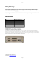
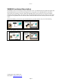
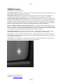
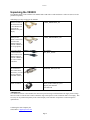
VR2003
User Manual
VRX Company Inc.
Version 1
Federal Communications Commission Radio Frequency Interference Declaration of Conformity Statement.
This equipment has been tested and found to comply with the limits for a Class B digital device, pursuant to part 15
of the FCC Rules. These limits are designed to provide reasonable protection against harmful interference in a
residential installation. This equipment generates, uses, and can radiate radio frequency energy and, if not installed
and used in accordance with the instructions, may cause harmful interference to radio communications. However,
there is no guarantee that interference will not occur in a particular installation. If this equipment does cause harmful
interference to radio or television reception, which can be determined by turning the equipment off and on, the user
is encouraged to try to correct the interference by one or more of the following measures:
—Reorient or relocate the receiving antenna.
—Increase the separation between the equipment and receiver.
—Connect the equipment into an outlet on a circuit different from that to which the receiver is connected.
—Consult the dealer or an experienced radio/ TV technician for help.
This device complies with part 15 of the FCC Rules. Operation is subject to the following two conditions: (1) This
device may not cause harmful interference, and (2) this device must accept any interference received, including
interference that may cause undesired operation.
NOTICES
This manual is copyrighted by the VRX Company Inc. Reproduction of any part of this manual in any form without
the express permission of the VRX Company Inc. is forbidden.
The contents of this manual are subject to change without notice. All efforts have been made to ensure the accuracy
of the contents of this manual. However, the VRX Company Inc. reserves the right to change this manual, the
product and the product operation for improvement without notice. If you find errors in this manual, please bring it
to our attention.
Table of Contents
Safety Warnings ............................................................................................................................................................3
Abbreviations ................................................................................................................................................................3
VR2003 Product Description.........................................................................................................................................3
VR2003 Functional Description ....................................................................................................................................4
VR2003 Features ...........................................................................................................................................................5
Unpacking the VR2003 .................................................................................................................................................6
VR2003 Setup and Connections ....................................................................................................................................7
Check and Set Serial BPS. ........................................................................................................................................7
Connection as a POS pole display adapter................................................................................................................7
Connection as a POS receipt printer adapter.............................................................................................................8
Connection as a receipt printer to POS input of DVR adapter..................................................................................8
Troubleshooting common problems. .............................................................................................................................9
Contacting the VRX Company Inc.
Send email to: [email protected].
Page 2
Version 1
Safety Warnings
Safety warning! If supplying power at the +9V jack, use only a safety approved AC adapter providing
between 9 and 12 Volts DC and rated for continuous usage at 150 mA. The adapter should have a positive
center conductor with a 2.1mm jack plug.
Safety warning! The VR2003 is rated for indoor home or office use only. Do not expose to moisture or rain.
Abbreviations
ECP
Enhanced Capabilities Port
EPP
Enhanced Parallel Port
LED
Light Emitting Diode
OSD
On Screen Display
PC
Personal Computer
POS
Point of Sale
RS170
NTSC Video Standard
SPP
Standard Parallel Port
USB
Universal Serial Bus
Table 1 Abbreviations used in this manual
VR2003 Product Description.
The VR2003 is an electronic device approximately 6 ¼ x 4 x 2 ¼ inches. It is a bridge to a Point of Sale pole
display or receipt printer and a video recording system. The VR2003 is a micro controller and On Screen Display
Integrated Circuit. Additionally, the VR2003 can be used to convert the receipt printer output to a serial stream for
input to a DVR if needed. A photo of the VR2003 is shown below.
Contacting the VRX Company Inc.
Send email to: [email protected].
Page 3
Version 1
VR2003 Functional Description
The VR2003 is a device to encourage accuracy at the point of sale. The VR2003 allows the product description and
pricing information sent to a point of sale pole display or a receipt printer to be embedded into the video from a
video camera for recording on VCR or a DVR. This embedded video is also referred to as an on-screen display,
commonly abbreviated as OSD. The recorded video with OSD information allows the store manager to review sales
to check for correspondence between what the cashier entered and what the customer actually received at the point
of sale.
Without the VR2003, you can review your recorded video on your video monitor, but you are left wondering.
But with the VR2003, you get the full story!
Contacting the VRX Company Inc.
Send email to: [email protected].
Page 4
Version 1
VR2003 Features
The VR2003 has the following features:
Power Indicator LED. The indicator will blink slowly to indicate normal operation when the VR2003 is idle. The
indicator toggles with each character sent to the OSD.
Configuration Mode Switch. This switch allows for configuration of the device to match the pole display or
receipt printer that is attached to the VR2003. See the section Check and Set Serial BPS. for more details.
Serial port and Parallel port input and output. The serial ports and parallel ports are where data is captured and
simultaneously embedded into the video. Both the parallel port and serial port are looped through with input on the
top and output on the bottom. The parallel port will usually be connected to a receipt printer and the serial port to a
pole display. You may connect devices to either one or both port types. See VR2003 Setup for connection details.
However, sending data to both the pole display and the printer simultaneously is not recommended.
Power is normally provided by a USB cable from the POS PC. An optional wall mounted transformer, (9V at
150 mA) is available. If you have an unused USB port at the POS, the USB may be the easiest method of providing
power. If the POS is powered through an Uninterruptible Power Supply, the VR2003 is also automatically powered.
If a wall transformer is used it should be powered from the same source as the POS PC.
Video input and output. Typically, video from a video camera is connected at the VR2003 Video input and the
Video Output is connected to a VCR / DVR. All levels are 1V at 75 ohms and RS170 analog format.
User Interface. The operating status of the VR2003 is in the form of OSD messages. The User Interface can also
be accessed by a serial port connection using a program such as Microsoft HyperTerminal (tm). See the section on
VR2003 Setup and Connections.
Alert Character. The VR2003 places a graphics character in the lower right OSD character cell. This provides a
visual indication that the VR2003 is in line with video and working correctly.
Contacting the VRX Company Inc.
Send email to: [email protected].
Page 5
Version 1
Unpacking the VR2003
The VR2003 usually comes with the Users Manual and a USB cable or wall transformer. Other accessories are also
purchased separately.
Other things you may need to use the VR2003:
Straight-through
DB9 serial cables to
reach from the POS
to the VR2003 and
then from the
VR2003 to the pole
display.
Part Number:
CABLE_DB9M-DB9F_2M
Straight-through
DB25 parallel
cables to reach from
the POS to the
VR2003 and then
from the VR2003 to
the receipt printer.
Part Number:
CABLE_DB25M-DB25F_2M
Two Video cables
to reach from the
video camera to the
VR2003 and then
from the VR2003 to
the video recorder
or monitor.
Part Number:
RCA_RCA_6FOOT
If your video cables
are terminated in
male contact BNC
connectors, you will
need two adapters
from BNC to RCA.
Part Number:
ADAPTER_BNCF_RCAM
DC Transformer
9VDC at 150mA*
VRX Part Number:
TRAN_9VDC150MA_P7_PLG
Digi-Key Part Number:
T205-P7P-ND
*IMPORTANT:
If a USB Power Source is not available, the unit can be powered using a wall transformer DC supply with a voltage
between 9 and 12 Volts rated at 150 mA continuous usage with a positive center connection and a 2.1mm plug. This
accessory can be purchased separately from VRX Company or the customer can purchase a unit meeting these
qualifications.
Contacting the VRX Company Inc.
Send email to: [email protected].
Page 6
Version 1
VR2003 Setup and Connections
Several connection configurations are possible for the VR2003 to the POS / DVR or VCR system. The first
configuration is connection between the POS and a pole display. The second configuration is to connect the
VR2003 to a receipt printer using a parallel port. A third configuration is to convert the output from a receipt printer
to a serial for input to a DVR. The first and third configurations require a correct serial port BPS setting of the
VR2003.
Check and Set Serial BPS.
To check or set the serial baud rate BPS (Bits per second) you must connect the VR2003 either to a video source and
monitor or a PC serial port and run a terminal program such as Microsoft HyperTerminal ™. The VR2003 is
shipped from the factory at 9600 BPS. Set your terminal program to 9600 initially. If the VR2003 is at a different
BPS, you will have to use trial and error on your terminal program’s BPS to find the current VR2003 BPS rate.
When you apply power to the VR2003, you will see a brief display of “VR2003-OK”. This will tell you that you
have the correct BPS rate on your terminal setting.
Using the tip of a pen or similar tool, Press SW1 briefly and you will observe a menu with instructions to select
features such as BPS. Follow the instructions to select and store the correct BPS to match your POS PC and Pole
display or DVR POS data input. All serial devices must be set to the same BPS to function correctly. After the new
settings are stored in the nonvolatile memory of the VR2003, it will reset to normal operation.
Connection as a POS pole display adapter.
Before connecting the VR2003, ensure normal operation of the pole display with the POS PC. Find the serial port
speed from the setup of the POS software. Set the serial port speed of the VR2003 to match. See the Check and Set
Serial BPS. section for further detail to set the VR2003 baud rate. Power down both the POS PC and pole display.
Disconnect the pole display from the POS PC. Connect a straight-through DB9 female to DB9 male cable from the
serial port on the PC to the top DB9 connector on the VR2003. Connect the pole display DB9 female connector to
the bottom DB9 connector on the VR2003. Connect the video camera video to the video input (top RCA connector)
of the VR2003. Connect the video output (bottom RCA connector) of the VR2003 to a video monitor or video
recorder. Power on the POS PC, the pole display, VR2003, and the video recorder or video monitor. You should see
the power on OSD message on the video display i.e. “VR2003 OK”. You should see normal camera video. Make a
transaction on the POS and verify proper operation of the pole display. Observe the video monitor for correct
camera video. The inserted OSD should reflect the transaction with similar information as the pole display. The
OSD will clear a short time after the VR2003 stops receiving characters. In this configuration, there is typically no
connection at the VR2003 parallel input or output.
NOTE:
• Due to the simple character set supported by the VR2003, the VR2003 suppresses multiple spaces, extra
blank lines, and uses a treble clef for a dollar sign. Many punctuation marks and “graphic” symbols are
highly simplified on the OSD. This is normal.
Contacting the VRX Company Inc.
Send email to: [email protected].
Page 7
Version 1
Connection as a POS receipt printer adapter.
Before connecting the VR2003, ensure normal operation of the receipt printer with the POS PC. Power down the
POS PC and the receipt printer. Disconnect the receipt printer from the POS PC. Connect a straight-through DB25
male to DB25 female from the printer port on the PC to the top DB25 connector on the VR2003. Connect the
receipt printer DB25 male connector to the bottom DB25 connector on the VR2003. Connect the video camera
video to the video input (top RCA connector) of the VR2003. Connect the video output (bottom RCA connector) of
the VR2003 to a video monitor. Power on the POS PC, the receipt printer, the VR2003, and the video monitor or
video recorder. Observe the video monitor for correct camera video. You should see the power on OSD message i.e.
“VR2003 OK”. Make a transaction on the POS, print a receipt and verify proper operation of the receipt printer.
The inserted OSD should reflect the transaction with similar information as the receipt printer.
The OSD will clear a short time after the VR2003 stops receiving characters. In this configuration, there is typically
no connection at the VR2003 serial input or output.
NOTE:
• Due to the simple character set supported by the VR2003, the VR2003 suppresses multiple spaces, extra
blank lines, and uses a treble clef for a dollar sign. Many punctuation marks and “graphic” symbols are
highly simplified on the OSD. This is normal.
• The line spacing will appear quite different due to the smaller number of characters per line available on
the OSD. This is normal.
Connection as a receipt printer to POS input of DVR adapter.
This mode would be used when the POS hardware or software does not support a pole display. In this case, the
VR2003 can convert the Receipt Printer output into a serial stream for the DVR.
Before connecting the VR2003, ensure normal operation of the receipt printer with the POS PC. Power down the
POS PC and the receipt printer. Disconnect the receipt printer from the POS PC. Connect a straight-through DB25
male to DB25 female from the printer port on the PC to the top DB25 connector on the VR2003. Connect the
receipt printer DB25 male connector to the bottom DB25 connector on the VR2003. Connect a straight-through
DB9 female to DB9 male from the bottom DB9 connector on the VR2003 to the serial port on the DVR PC. Power
on the DVR. Observe the video monitor. Power on the POS PC, receipt printer, VR2003 and video monitor or video
recorder. You should see the power on OSD message on the DVR i.e. “VR2003 OK”. Make a transaction on the
POS, print a receipt and verify proper operation of the receipt printer and display on the video recorder. In this
configuration, there is typically no connection at the VR2003 serial input.
NOTE:
• Optionally, you can connect the RCA cables for Video input and output. However, some DVR’s will
generate an internal Overlay using the serial input data.
Contacting the VRX Company Inc.
Send email to: [email protected].
Page 8
Version 1
Troubleshooting common problems.
First check for correct connection and that all connections are properly tight and then turn off the power to
everything, wait 10 seconds and reapply power. Check for LED normal operation.
Symptom
Power LED not
blinking or not lit
Power LED stays
on
No video output
No OSD text from
serial pole display
No text printed on
Receipt Printer
No OSD text from
receipt printer
OSD for receipt
different format as
from printer.
DVR not receiving
serial data or serial
data corrupted
Possible Cause and Resolution
Possible cause: No power. Resolution: Check Power Connection. The VR2003 requires a
power connection from either a connection through a cable to a USB host or a wall
transformer.
Possible cause: Stuck in User Interface Mode. Resolution: Disconnect power from the
VR2003, wait 10 seconds and reapply power. Check that nothing is accidentally pressing the
SW1 switch during normal operation.
Possible cause: No video input. Resolution: The VR2003 does not generate video in the
absence of an input video signal. You must provide both a video input as, well as connect a
monitor or television to the video output. When power is applied look for the brief display of
“VR2003 OK”, followed by the “Alert” character displayed in the lower right of the screen.
Possible cause: Bad cables, Incorrect (nullmodem cable), contention from pole display.
Disconnect the pole display if connected. Resolution: Connect only a single cable from the
DB9 on the PC to the VR2003. The cable should be female to male straight-through. DO
NOT USE A NULL MODEM CABLE. Check serial communication rate and change either
the PC or the VR2003 serial communication as necessary to get them communicating. Please
refer to section Check and Set Serial BPS.. Then make any necessary changes to the serial
communication on the pole display to match the settings found to work with the VR2003
alone. Then connect the pole display to the serial output of the VR20003 and test again. Also,
try connecting the pole display directly to the output of the POS serial output with as little
cable as possible. Continue adding in the other cables and finally the VR2003.
Possible cause: Bad Cable or connections, no hand shaking from printer. Resolution: Check
that the receipt printer is connected, on line and has paper. For the parallel port interface to
work the VR2003 and a receipt printer must be connected. The POS PC expects correct
handshaking from the printer before the interface can send data. Check that the POS PC and
the receipt printer can work together correctly with just the cable from the PC to the receipt
printer. This cable typically has DB25 female connector on one end and a CENTRONICS™
connector on the other end. Verify correct printer operation then add only the additional DB25
female to Male cable. This cable in normal operation will go from the PC to the VR2003
parallel input. Verify correct printer operation. Add the VR2003. Verify operation of the
receipt printer.
Possible cause: Incompatible parallel port setting. Resolution: Verify receipt printer is
working correctly. Try changing BIOS setting to SPP (Standard Parallel Port) or EPP
(Enhanced Parallel Port). NOTE: THE UNIT WILL NOT WORK PROPERLY IF THE BIOS
IS SETUP AS ECP (ENHANCED CAPABILITIES PORT). There is quite a bit of variation
in how manufacturers configure the parallel port in the BIOS, you may have to consult the
user manual that came with your computer.
Resolution: The formatting will be quite different due to the smaller number of characters per
line available on the OSD. This is normal.
Possible cause: Incompatible parallel port setting, too long serial cable or no handshaking.
Resolution: Verify receipt printer is working correctly. Try changing BIOS setting to SPP
(Standard Parallel Port) or EPP (Enhanced Parallel Port). NOTE: THE UNIT WILL NOT
WORK PROPERLY IF THE BIOS IS SETUP AS ECP (ENHANCED CAPABILITIES
PORT). There is quite a bit of variation in how manufacturers configure the parallel port in
the BIOS, you may have to consult the user manual that came with your computer.
Very long serial cables limit the usable BPS. And the VR2003 does not have hand shaking so
the DVR can not keep up to the serial transmission Both the problem due to a very long serial
Contacting the VRX Company Inc.
Send email to: [email protected].
Page 9
Version 1
DB9 or DB25
cable does not fit
cable and no handshaking may be cured by setting both the VR2003 and the DVR to a slower
BPS.
Resolution: Due to the narrow vertical spacing on the input and output connections, some
cables with large amounts of molded insulation on the connectors may not fit easily. In this
case, use a different cable that does fit correctly. These can be purchased from the VRX
Company.
VR2003 LIMITED WARRANTY
VRX Company Inc. (“VRX”) and VRX’s authorized distributors warrant to the original purchaser that the product shall be free from defect in material and/or workmanship for a period of one
(1) year from the date of purchase. The service parts stock for this model shall be maintained for 3 years after the production is discontinued.
In the event of malfunction during the warranty period attributable directly to faulty material and/or workmanship, VRX and VRX’s authorizes distributors will, at their option, either repair or
replace the faulty product with the same or similar model. VRX and VRX’s authorized distributors shall have no obligation under this warranty, however, in the following cases:
(a) Any defect caused by freight damage, modification, alteration, abuse, misuse, accident, incorrect installation, disaster, faulty maintenance or improper repair by third party other than VRX
and VRX’s authorizes distributors.
(b) Any incompatibility of the products with subsequent technical innovations or regulations.
(c) Any defect of the product caused by external equipment.
(d) Any defect of the product on which the original serial number has been altered or removed.
Once the warranty period has expired, the warranty on any replaced and/or repaired part also expires.
VRX AND VRX’S AUTHORIZED DISTRIBUTORS MAKE NO FURTHER WARRANTIES, EXPRESS OR IMPLIED, WITH RESPECT TO THE PRODUCT AND ITS QUALITY,
PERFORMANCE, MERCHANTABILITY OR FITNESS FOR ANY PARTICULAR USE. IN
NO EVENT SHALL VRX AND VRX’S AUTHORIZES DISTRIBUTORS BE LIABLE FOR ANY SPECIAL, CONSEQUENTIAL, INCIDENTAL OR OTHERS DAMAGES (INCLUDING,
WITHOUT LIMITATION, LOSS OR PROFIT) WHETHER OR NOT VRX AND VRX’S AUTHORIZED DISTRIBUTORS HAVE BEEN ADVISED OF THE POSSIBILITY OF SUCH
DAMAGES, ARISING OUT OF ANY BREACH OR REPUDIATION OF CONTRACT, OR WARRANTY, NEGLIGENCE, OR OTHERWISE. THIS EXCLUSION ALSO INCLUDES ANY
LIABILITY WHICH MAY ARISE OUR OF THIRD PARTY CLAIMS AGAINST THE ORIGINAL PURCHASER. THE ESSENCE OF THE PROVISION IS TO LIMIT THE POTENTIAL
LIABILITY OF VRX AND VRX’S AUTHORIZES DISTRIBUTORS ARISING OUT OF THIS AGREEMENT AND/OR SALES.
Service Procedure
To obtain service please contact the VRX Company for instructions.
For warranty service, the original purchaser must present proof of purchase establishing proof and date of purchase of the product when
requesting warranty service.
Before a product is returned to be serviced, the purchaser must obtain a Return Material Authorization number so that the VRX Company can
uniquely identify the product returned. The purchaser must deliver the product, freight prepaid, in its original package or other adequate package
affording an equal degree of protection, assuming the risk of damage and/or loss in transit, to your local VRX authorized distributor. The RMA
number must be clearly marked on the exterior of the packaging.
Contact the VRX Company Inc at [email protected] or by calling 1-865-805-2437.
Contacting the VRX Company Inc.
Send email to: [email protected].
Page 10