1
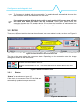
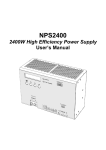
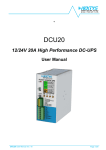
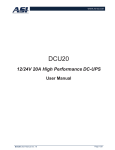
Configuration and diagnostic tool POWERMASTER Configuration and diagnostic tool User Manual POWERMASTER user manual rev. 1.4 Page 1/10 Configuration and diagnostic tool Table of contents: 1 2 3 Introduction....................................................................................................................................4 Installation .....................................................................................................................................4 Functional description ....................................................................................................................5 3.1 NPS2400 ...............................................................................................................................5 3.1.1 Status ..............................................................................................................................6 3.1.2 Settings ...........................................................................................................................7 3.1.3 Logs.................................................................................................................................7 3.1.4 Info ..................................................................................................................................7 3.2 DCU20 ..................................................................................................................................8 3.2.1 Status ..............................................................................................................................8 3.2.2 Logger .............................................................................................................................9 3.2.3 Settings ...........................................................................................................................9 3.2.4 Logs...............................................................................................................................10 3.2.5 Info ................................................................................................................................10 POWERMASTER user manual rev. 1.4 Page 2/10 Configuration and diagnostic tool DISCLAIMER NEXTYS reserves the right to make changes without further notice to any products herein. NEXTYS makes no warranty, representation or guarantee regarding the suitability of its products for any particular purpose, nor does NEXTYS assume any liability arising out of the application or use of any product, and specifically disclaims any and all liability, including without limitation consequential or incidental damages. “Typical" parameters which may be provided in NEXTYS data sheets and/or specifications can and do vary in different applications and actual performance may vary overtime. All operating parameters, including “Typicals", must be validated for each customer application by customer's technical experts. NEXTYS does not convey any license under its patent rights nor the rights of others. NEXTYS products are not designed, intended, or authorized for use as components in systems intended for surgical implant into the body, or other applications intended to support or sustain life, or for any other application in which the failure of the NEXTYS product could create a situation where personal injury or death may occur. Should Buyer purchase or use NEXTYS products for any such unintended or unauthorized application, Buyer shall indemnity and hold NEXTYS and its officers, employees, subsidiaries, affiliates, and distributors harmless against all claims, costs, damages, and expenses, and reasonable attorney fees arising out of, directly or indirectly, any claim of personal injury or death associated with such unintended or unauthorized use, even if such claim alleges that NEXTYS was negligent regarding the design or manufacture of the part. The Customer should ensure that it has the most up to date version of the document by contacting its local NEXTYS office. This document supersedes any earlier documentation relating to the products referred to herein. The information contained in this document is current at the date of publication. It may subsequently be updated, revised or withdrawn. All Trade Marks recognized. Specifications and information herein are Subject to change without notice. POWERMASTER user manual rev. 1.4 Page 3/10 Configuration and diagnostic tool 1 Introduction POWERMASTER is a software tool used to configure and monitor the operation of the following products: NPS2400: Advanced 3 Phases 2400W DIN rail power supply. DCU20: CPU controlled 12/24V – 20A DC UPS. Reader of this document should be familiar with the mentioned products, at this purpose reading of the NPS2400 and DCU20 user manual is recommended. With POWERMASTER the user can: Monitor the device status. Update the firmware. Read and write the device configuration. Read and write the configuration from/to a file. Read the logs. Read and write the logs from/to a file. 2 Installation Simply run “SETUP-POWERMASTER-XX.exe” (where XX is replaced with the release number) and follow the instructions on the screen until the end of the installation process. POWERMASTER application can be installed on any PC running windows XP, windows 7 (32 and 64bits) or window 8 (32 and 64bits). USB driver are bundled with POWERMASTER application. Install the application before connecting the device to the PC with USB. POWERMASTER user manual rev. 1.4 Page 4/10 Configuration and diagnostic tool 3 Functional description On POWERMASTER start-up, the user must select the device type as shown on Figure 1. Figure 1: Start-up screen User can operate the application in two ways: Offline: This mode is active when the device is disconnected from the PC. The user can perform a limited number of activities, all activities that require the device connected are disabled. Online: This mode is active when the device is connected to the PC. The user can benefit of all the functionalities. 3.1 NPS2400 To connect the NPS2400 to the PC the CommBox (Communication Box) is mandatory. The CommBox must be inserted into the dedicated slot on the NPS2400 (see Figure 2) and plugged to the PC using the provided USB cable. Connect the main supply input to power on the device. In case only single phase is available, it is possible to connect neutral and phase between L1 and L2 to power on the device. The DC output will not work and the under voltage alarm will be shown on the screen, but it will be possible to communicate with the device. Figure 2: CommBox connection There are 4 different activities that can be performed, each one related to a tab, as shown on Figure 3 and described later. POWERMASTER user manual rev. 1.4 Page 5/10 Configuration and diagnostic tool Figure 3: NPS2400 activities and connection state The top of the page shows the connection state. Depending on the connection state the image changes as shown on the table below. PC – CommBox disconnected, CommBox – NPS2400 disconnected PC – CommBox connected, CommBox – NPS2400 disconnected PC – CommBox connected, CommBox – NPS2400 connected Table 1: NPS2400 connection state 3.1.1 Status To view the connected device status select the “Status” tab as shown on Figure 4. If the device is connected to the PC the fields are automatically read and updated once per second, otherwise the string “Not connected” is displayed. Figure 4: NPS2400 status POWERMASTER user manual rev. 1.4 Page 6/10 Configuration and diagnostic tool 3.1.2 Settings This tab contains all the device settings, 4 buttons are available to the user: Read from device: Used to read the settings from the connected device. This button is enabled only if a device is connected. Write to device: Used to write the displayed settings to the connected device. This button is enabled only if a device is connected. Read from file: Used to read settings from previously saved file. Write to file: Used to write the displayed settings to a file. The file type is .xml. Read on connection: Select to automatically read settings on device connection. Figure 5: NPS2400 settings 3.1.3 Logs The log panel shows the logs present on the device, 4 buttons are available to the user: Read from device: Used to read the logs from the connected device. This button is enabled only if a device is connected. Read from file: Used to read logs from a previously saved file. Write to file: Click to write the logs to a file. The file type is .xml. Export to excel: Click to export the logs in excel format. Read on connection: Select to automatically read logs on device connection. Figure 6: NPS2400 logs 3.1.4 Info From the info panel user can view the firmware version, name and serial of the connected NPS2400. The “Update” button is used to update the device with a new firmware. User can change the name of the device from this panel. Figure 7: NPS2400 info POWERMASTER user manual rev. 1.4 Page 7/10 Configuration and diagnostic tool The firmware is bundled with the executable. The application will automatically choose the latest firmware version and download it to the device. If the update procedure fails the device will not work and the LCD screen stays off, but even from this status the device can be recovered. In this case please check the connection between the PC and the device. Ensure that the CommBox is well inserted into the NPS2400 slot and then launch the update procedure again. 3.2 DCU20 There are 5 different activities that can be performed, each one related to a tab, as shown on Figure 8 and described later. Figure 8: DCU20 activities and connection state The top of the page shows the connection state. Depending on the connection state the image changes as shown on the table below. DCU20 is not connected to the PC. DCU20 is connected to the PC. The arrows become blue when data is sent over USB. Figure 9: DCU20 connection state 3.2.1 Status To view the current device status select the “Status” tab as shown on Figure 10. If the device is connected to the PC the fields are automatically updated once per seconds. Figure 10: DCU20 status POWERMASTER user manual rev. 1.4 Page 8/10 Configuration and diagnostic tool 3.2.2 Logger This tab is used to show measured data on a chart and/or save them to an excel file, 5 controls are available to the user: Enable: When selected the collected points are added to the chart. Show points: When selected the points markers are shown on the chart. Clear points: Used to clear all points form the chart. Zoom all: Used to adjust the chart zoom making all points visible. Start save to file: Used to save the collected points to an excel file. Figure 11: DCU20 logger 3.2.3 Settings This tab contains all the DCU20 settings, 4 buttons are available to the user: Read from device: Used to read the settings from the connected device. This button is enabled only if a device is connected. Write to device: Used to write the displayed settings to the connected device. This button is enabled only if a device is connected. Read from file: Used to read settings from previously saved file. Write to file: Used to write the displayed settings to a file. The file type is .xml. Read on connection: Select to automatically read setting on device connection. Figure 12: DCU20 settings POWERMASTER user manual rev. 1.4 Page 9/10 Configuration and diagnostic tool 3.2.4 Logs The events logs present on the connected device can be read from this panel, 3 buttons are available to the user: Read from device: Used to read the logs from the connected device. This button is enabled only if a device is connected. Read from file: Used to read logs from a previously saved file. Write to file: Click to write the logs to a file. The file type is .xml. Read on connection: Select to automatically read logs on device connection. Figure 13: DCU20 logs 3.2.5 Info From the help panel user can view several information about the connected device. The “Update” button is used to update the DCU20 with a new firmware. User can change the name of the device from this panel. Figure 14: DCU20 info The firmware is bundled with the executable. The application will automatically choose the latest firmware version and download it to the device. If the update procedure fails the device will not work and the LCD screen stays off, but even from this status the device can be recovered. In this case please check the connection between the PC and the device and then launch the update procedure again. POWERMASTER user manual rev. 1.4 Page 10/10