1
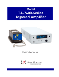
Model 764H Series
High Power LD Mount
User’s Manual
ii
Preface
Dear Customer,
This User Manual contains essential information, including safety
precautions and start up procedures, needed to get your new
instrument up and running. Please review it prior to unpacking and
powering up the instrument.
In an effort to keep the Newport instruments optimized for your
applications, Newport will on occasion update existing and add
new features and documents. You can find the latest User
Manual, application software, Start-up Guide, or firmware at the
product page on the Newport web site (www.Newport.com).
Call your local Newport application specialist if you need
support with locating or downloading these files.
Enjoy your new product!
Preface
iii
Warranty
Newport Corporation warrants that this product will be free from defects in
material and workmanship and will comply with Newport’s published
specifications at the time of sale for a period of one year from date of
shipment. If found to be defective during the warranty period, the product
will either be repaired or replaced at Newport's option.
To exercise this warranty, write or call your local Newport office or
representative, or contact Newport headquarters in Irvine, California. You
will be given prompt assistance and return instructions. Send the product,
freight prepaid, to the indicated service facility. Repairs will be made and the
instrument returned freight prepaid. Repaired products are warranted for the
remainder of the original warranty period or 90 days, whichever first occurs.
Limitation of Warranty
The above warranties do not apply to products which have been repaired or
modified without Newport’s written approval, or products subjected to
unusual physical, thermal or electrical stress, improper installation, misuse,
abuse, accident or negligence in use, storage, transportation or handling.
THIS WARRANTY IS IN LIEU OF ALL OTHER WARRANTIES,
EXPRESSED OR IMPLIED, INCLUDING ANY IMPLIED WARRANTY
OF MERCHANTABILITY OR FITNESS FOR A PARTICULAR USE.
NEWPORT CORPORATION SHALL NOT BE LIABLE FOR ANY
INDIRECT, SPECIAL, OR CONSEQUENTIAL DAMAGES RESULTING
FROM THE PURCHASE OR USE OF ITS PRODUCTS.
First printing 2009
© 2009 by Newport Corporation, Irvine, CA. All rights reserved. No part of
this manual may be reproduced or copied without the prior written approval
of Newport Corporation.
This manual has been provided for information only and product
specifications are subject to change without notice. Any change will be
reflected in future printings.
Newport Corporation
1791 Deere Avenue
Irvine, CA, 92606
USA
Part No. 90032670 rev B
iv
Preface
Confidentiality & Proprietary Rights
Reservation of Title:
The Newport programs and all materials furnished or produced in connection
with them ("Related Materials") contain trade secrets of Newport and are for
use only in the manner expressly permitted. Newport claims and reserves all
rights and benefits afforded under law in the Programs provided by Newport
Corporation.
Newport shall retain full ownership of Intellectual Property Rights in and to
all development, process, align or assembly technologies developed and other
derivative work that may be developed by Newport. Customer shall not
challenge, or cause any third party to challenge the rights of Newport.
Preservation of Secrecy and Confidentiality and Restrictions to Access:
Customer shall protect the Newport Programs and Related Materials as trade
secrets of Newport, and shall devote its best efforts to ensure that all its
personnel protect the Newport Programs as trade secrets of Newport
Corporation. Customer shall not at any time disclose Newport's trade secrets
to any other person, firm, organization, or employee that does not need
(consistent with Customer's right of use hereunder) to obtain access to the
Newport Programs and Related Materials. These restrictions shall not apply
to information (1) generally known to the public or obtainable from public
sources; (2) readily apparent from the keyboard operations, visual display, or
output reports of the Programs; 3) previously in the possession of Customer
or subsequently developed or acquired without reliance on the Newport
Programs; or (4) approved by Newport for release without restriction.
Trademarks
The Newport logo is a registered trademark of Newport Corporation in
Austria, Barbados, Benelux, Canada, the People’s Republic of China,
Denmark, France, Germany, Great Britain, Ireland, Japan, the Republic of
Korea, Spain, Sweden, and the United States.
Service Information
This section contains information regarding factory service for the source.
The user should not attempt any maintenance or service of the system or
optional equipment beyond the procedures outlined in this manual. Any
problem that cannot be resolved should be referred to Newport Corporation.
Preface
v
Technical Support Contacts
North America & Asia
Newport Corporation Service Dept.
1791 Deere Ave. Irvine, CA 92606
Telephone: (949) 253-1694
Telephone: (800) 222-6440 x31694
Europe
Newport/MICRO-CONTROLE S.A.
Zone Industrielle
45340 Beaune la Rolande, FRANCE
Telephone: (33) 02 38 40 51 56
Asia
Newport Opto-Electronics
Technologies
中国 上海市 爱都路 253号 第3号楼 3层
C部位, 邮编 200131
253 Aidu Road, Bld #3, Flr 3, Sec C,
Shanghai 200131, China
Telephone: +86-21-5046 2300
Fax: +86-21-5046 2323
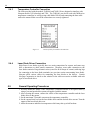
Newport Corporation Calling Procedure
If there are any defects in material or workmanship or a failure to meet
specifications, promptly notify Newport's Returns Department by calling 1-800-2226440 or by visiting our website at www.newport.com/returns within the warranty
period to obtain a Return Material Authorization Number (RMA#). Return the
product to Newport Corporation, freight prepaid, clearly marked with the RMA# and
we will either repair or replace it at our discretion. Newport is not responsible for
damage occurring in transit and is not obligated to accept products returned without
an RMA#.
E-mail: [email protected]
When calling Newport Corporation, please provide the customer care representative
with the following information:
• Your Contact Information
• Serial number or original order number
• Description of problem (i.e., hardware or software)
To help our Technical Support Representatives diagnose your problem,
please note the following conditions:
•
•
•
•
Is the system used for manufacturing or research and development?
What was the state of the system right before the problem?
Have you seen this problem before? If so, how often?
Can the system continue to operate with this problem? Or is the system
non-operational?
• Can you identify anything that was different before this problem
occurred?
vi
Preface
Table of Contents
Warranty................................................................................................ iii
Technical Support Contacts ................................................................... v
Table of Contents .................................................................................. vi
List of Figures ...................................................................................... vii
List of Tables ....................................................................................... vii
1
Safety Precautions
1.1
1.2
2
3
5
5.3
5.4
8
Choosing and Preparing a Suitable Work Surface ....................... 9
System Operation
5.1
5.2
7
Unpacking and Handling.............................................................. 7
Inspection for Damage ................................................................. 7
Parts List
4.1
5
Introduction .................................................................................. 5
Specifications ............................................................................... 5
Getting Started
3.1
3.2
4
Definitions and Symbols .............................................................. 1
1.1.1 General Warning or Caution .............................................1
1.1.2 Waste Electrical and Electronic Equipment (WEEE) .......1
Warnings and Cautions................................................................. 2
1.2.1 General Warnings..............................................................2
1.2.2 General Cautions ...............................................................2
1.2.3 Summary of Warnings and Cautions.................................3
General Information
2.1
2.2
1
10
Heat Load Calculation................................................................ 10
High Power Laser Diode Mount Anatomy................................. 12
5.2.1 Main Heat Transfer Unit .................................................12
5.2.2 Copper Cold Plate............................................................12
5.2.3 Support System................................................................12
5.2.4 Electrical Connections.....................................................12
Laser Diode Handling Precautions............................................. 14
Laser Diode Mounting................................................................ 15
5.4.1 Mounting the Laser Diodes and Wire Connection ..........15
5.4.2 Terminal Block Connections...........................................19
5.4.3 Temperature Controller Connection................................20
Preface
5.5
6
5.4.4 Laser Diode Driver Connection.......................................20
General Operating Procedures.................................................... 20
Maintenance and Service
6.1
6.2
7
vii
Obtaining Service ....................................................................... 22
Service Form .............................................................................. 23
Appendix
7.1
7.2
22
24
764H-061 Top Plate Dimensions ............................................... 24
764H-110 Top Plate Dimensions ............................................... 25
List of Figures
Figure 1
Figure 2
Figure 3
Figure 4
Figure 5
Figure 6
Figure 7
Figure 8
Figure 9
Figure 10
Figure 11
Figure 12
Figure 13
Figure 14
Figure 15
General Warning or Caution Symbol.........................................1
WEEE Directive Symbol..............................................................1
Model 764H-061 base mounting options.....................................9
Model 764H-110 heat removal performance chart.................11
Model 764H-061 mounting hardware and electrical
connections ..................................................................................13
Model 764H-110 mounting hardware and electrical
connections ..................................................................................13
Model 764H-110 mount (photo with special hole pattern on
top plate) ......................................................................................15
SIL Pads for thermal coupling with cold plate ........................16
Hole patterns on 764H-061 top plate for Oclaro’s Orion H2
and H3 package styles ................................................................17
Hole patterns on 764H-110 top plate ........................................17
Mounting screws for BWA series LD .......................................18
BWA laser diode shown as an example ....................................18
LD wire connections ...................................................................19
Terminal block connections .......................................................19
Pinout of cable for models 3150 and 3700 ................................20
List of Tables
Table 1
Table 2
Table 3
Table 4
General Specifications ..................................................................5
Environmental Specifications ......................................................6
List of parts included in 764H mount ........................................8
Acessory and spare parts list .......................................................8
1
Safety Precautions
1.1
Definitions and Symbols
The following terms and symbols are used in this documentation where
safety-related issues occur.
1.1.1
General Warning or Caution
Figure 1
General Warning or Caution Symbol
The Exclamation Symbol in the figure above appears on the product and in
Warning and Caution tables throughout this document. This symbol
designates that documentation needs to be consulted to determine the nature
of a potential hazard, and any actions that have to be taken.
1.1.2
Waste Electrical and Electronic Equipment (WEEE)
Figure 2
WEEE Directive Symbol
This symbol on the product or on its packaging indicates that this product
must not be disposed of with regular waste. Instead, it is the user
responsibility to dispose of waste equipment according to the local laws. The
separate collection and recycling of the waste equipment at the time of
disposal will help to conserve natural resources and ensure that it is recycled
in a manner that protects human health and the environment. For information
about where the user can drop off the waste equipment for recycling, please
contact your local Newport Corporation representative. See Section 5 for
instructions on how to disassemble the equipment for recycling purposes.
2
Safety Precautions
1.2
Warnings and Cautions
The following are definitions of the Warnings, Cautions and Notes that are
used throughout this manual to call your attention to important information
regarding your safety, the safety and preservation of your equipment or an
important tip.
WARNING
Situation has the potential to cause bodily harm or death.
CAUTION
Situation has the potential to cause damage to property or
equipment.
NOTE
Additional information the user or operator should consider.
1.2.1
General Warnings
Observe these general warnings when operating or servicing this equipment:
• Heed all warnings on the unit and in the operating instructions.
• Do not use this equipment in or near water.
• This equipment is grounded through the connections to the laser diode
driver and TE controller.
• Route connecting cables so that they are not likely to be damaged.
• Disconnect power before cleaning the equipment. Do not use liquid or
aerosol cleaners; use only a damp lint-free cloth.
1.2.2
General Cautions
Observe these cautions when operating this equipment:
• If this equipment is used in a manner not specified in this manual, the
protection provided by this equipment may be impaired.
• Follow precautions for static sensitive devices when handling this
equipment.
• This product should only be powered as described in the manual.
Safety Precautions
3
• There are no user-serviceable parts inside the Model 764H series Laser
Diode Mounts.
• Adhere to good laser safety practices when using this equipment.
1.2.3
Summary of Warnings and Cautions
The following general warning and cautions are applicable to this instrument:
WARNING
Before operating the Models 764H Laser Diode Mount, please
read and understand all of Section 1.
WARNING
Do not attempt to operate this equipment if there is evidence of
shipping damage or you suspect the unit is damaged. Damaged
equipment may present additional hazards to you. Contact
Newport technical support for advice before attempting to plug
in and operate damaged equipment.
CAUTION
There are no user serviceable parts inside the Models 764H
Temperature Controlled Laser Diode Mount. Work performed by
persons not authorized by Newport Corporation will void the
warranty. For instructions on obtaining warranty repair or
service, please refer to Section 5.
5
2
General Information
2.1
Introduction
The Model 764H series High Power Laser Diode Mounts are industrial grade
Cold Plates adapted for research applications. These mounts are optimized
with Newport’s temperature controllers, specifically with Model 3700
temperature controller to provide most rapid settling time, and maintaining
the needed temperature regulation. The hardware included supports most
Oclaro (formerly Spectra-Physics) laser diode family. Custom or other laser
diode hole patterns can be created by the user relatively easily. The copper
alloy top plate is available for purchase as a spare part. Note that significant
amount of variations exist in laser diode package designs among
manufacturers. Therefore, before mounting any laser diode on the 764H
mount, contact the manufacturers and confirm all the dimensions of the
physical device.
2.2
Specifications
Model 764H-061
Types of Oclaro laser
diodes compatible
Max Heat Load Capacity
@ 25°C Ambient (2)
TE Power Rating
Platform Height +/Vertical Adjustment
Main Connectors
Other Connections
Temperature Range (3)
• SF Series (qty 1)
• BW/CW series (qty 1)
• Orion series (qty 1)
Model 764H-110
•
•
•
•
Orion series (qty 3)
BW/CW series (qty 2)
Prosario (qty 1)
Courvus (qty 1)
61 W
110 W
24VDC @ 6.0 Amps
24VDC @ 11 Amps
7.77” +1.5” / - 0”
(197.3 + 38.1 / -0 mm)
5.55”
Pigtailed Cable, D-Sub
7W2 Male
Power Supply
Pigtailed Cable, D-Sub
7W2 Male
Power Supply
-10°C to +80°C
-10°C to +80°C
Sensor Type
10 kΩ thermistor
10 kΩ thermistor
(1) Performance based on unrestricted air flow to heat sink and fan. In no case
should the ambient, cold plate, or heat sink temperature be allowed to exceed 70°C.
(2) Controller dependant
Table 1
General Specifications
6
General Information
Environmental Specifications
764H-061
764H-110
Size (H x W x D)
[in. (mm)]
5.55” x 4.72” x 7.87” ( 141
x 120 x 200)
7.77” x 5.75” x 8.70” ( 197.3
x 143 x 221)
Weight [lb (kg)]
8 Lbs (3.7 Kg)
11 Lbs (5 Kg)
Operating
(1)
Temperature
-10 °C to 50 °C Ambient
(<90% humidity non-condensing)
Storage Temperature
-30°C to + 70°C
(<90% humidity non-condensing)
Relative Humidity,
<90% humidity non-condensing
Storage
Use Location
Indoor use only
(1) Performance based on unrestricted air flow to heat sink and fan. In no case
should the ambient, cold plate, or heat sink temperature be allowed to exceed 70°C.
Table 2
Environmental Specifications
7
3
Getting Started
3.1
Unpacking and Handling
The High Power Laser Diode Mount is designed for easy setup and use. To unpack, remove
the Mount from its packaging.
3.2
•
Remove the zip ties from the cable and uncoil cable before connecting to the
Temperature Controller. The connecting cable is pre-attached to the mount from the
factory and is configured to work with the models 3150 (obsolete) and 3700 high
power temperature controllers.
•
Mounting accessories included in the box will make mounting of the product simple.
764H-110 comes with VPHV-2 post holders and clamps to hold the posts (posts
already attached to the LD mount) to the optical table surface. 764H-061 comes with
a mounting kit for user convenience.
•
Remove the blue plastic cover from the copper plate before mounting the laser diode.
Inspection for Damage
The LD Mount is carefully packaged at the factory to minimize the possibility of damage
during shipping. Inspect the box for external signs of damage or mishandling. Inspect the
contents of the box for damage. If there is visible damage upon receipt, inform the shipping
company and Newport Corporation immediately. You may consider saving the box in case
of shipping needs in the future.
WARNING
Do not attempt to operate this equipment if there is evidence of
shipping damage or you suspect the unit is damaged. Damaged
equipment may present additional hazards to you. Contact
Newport technical support for advice before attempting to plug
in and operate damaged equipment.
CAUTION
The user is advised to save the packaging material in case the
unit has to be shipped to a different location. The packaging
material is specially designed to protect the unit during
shipping.
8
4
Parts List
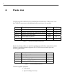
The following table contains the list of standard parts included in the 764H mounts. Note
that 764H-061 mount comes with additional washers and screws for assembly:
Part #
Description
764H-061
764H-110
90032670
User manual hardcopy
Qty 1
Qty 1
VPHV-2-F
ValuMax Post Holder & Clamping Fork Bundle
--
Qty 4
B-05A
Stainless Steel Slotted Base
Qty 4
--
1918-PS
Power Supply for the fan
Qty 1
Qty 1
1918-PSC
Power supply cable
Qty 1
Qty 1
Table 3
List of parts included in 764H mount
If parts are missing or there are questions regarding any of the above items, please contact
Newport Corporation technical support at 800-222-6440. Some of useful spare and
accessory parts include:
Part #
Description
Category
05173-01
Thermal paste, silicone
Accessory
FK-STRAP Grounding wrist strap
Accessory
90032542
Top plate for 764-110, copper
Spare
90032541
Top plate for 764H-061, copper
Spare
Table 4
Acessory and spare parts list
Customer supplied Equipment:
Laser diode
Special cabling if necessary
9
WARNING
Make sure of obtaining and understanding specifications of the
laser diode you are going to use on this mount, because there
are a multitude of commercially available high power laser diode
packages with various package styles and electrical
requirements. Request datasheets from laser manufacturers.
4.1
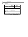
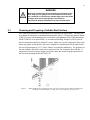
Choosing and Preparing a Suitable Work Surface
The 764H series mounts are recommended to be secured on an optical table. The setup can
be mounted to both metric or standard threaded tables with a 1” (25mm) hole pattern. Model
764H-110 comes with mounting posts, post holders, and tightening forks. When mounting a
Model 764H-061 on an optical table, we recommend attaching Newport’s B-05A bases at
the four bottom threaded holes using M5 screws. Make sure you don’t tighten the base to the
mount too tightly so that the base slot can be aligned to a mounting hole on the optical table.
An area of approximately 8”x 8” (200 x 200mm) is needed for installation. The perimeter of
the unit cannot be blocked or enclosed for proper air flow for cooling the heat sink fins. A
minimum of 50 mm clearance height is necessary under the mount for proper operation of
the fan when mounting the Model 764H-110.
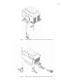
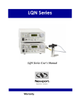
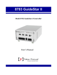
Figure 3
Model 764H-061 base mounting options. One can use either mount a B-05A slotted base for
mounting on an optical table, or simply put a sticky rubber foot at each corner.
10
5
System Operation
WARNING
Before operating the Models 764H series High Power Laser
Diode Mounts, please read and understand all of Section 1.
5.1
Heat Load Calculation
A simple way to approximately calculate your heat load is to use the following rule of
thumb. The heat load generated is the difference between the total electrical power going
into the laser diode (Current times Voltage) and the optical output power of the laser diode.
The current and voltage are input from the laser diode driver.
An example would be using a BW series Oclaro laser diode, at 40 Amps and 2.3 Volts
resulting in a total of 92 Watts electrical power input to the device. If the optical output
measured is 40 Watts, means 52 Watts of thermal heat is generated.
This calculation is only an approximation since there are additional heat loads on the mount
from the ambient temperatures and other possible inefficiencies within the mount depending
on the TEC drive current and voltage (the relationships are not simple calculations). It is
best to operate the system at less than 90 % of the maximum rated heat load for the specific
laser diode mount to avoid thermal runaway conditions. For multiple laser diodes attached
to the LD mount, similar calculations should be made.
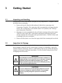
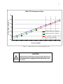
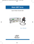
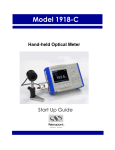
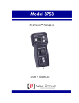
Please refer to figure 3 for a typical heat load performance graph of the Model 764H-110
mount.
11
764H-110 Performance Graph
60
∆T (Top Plate to Ambient ˚C)
40
20
0
Performance at 25˚C Ambient
-20
Performance at 50˚C Ambient
-40
50˚C Ambient, Operation in this
range not recommended
-60
0
20
40
60
80
100
120
140
160
Heat Load (Watts)
Figure 4
Model 764H-110 heat removal performance chart
CAUTION
Exceeding the maximum thermal load of the laser diode mount
will result in thermal run-away conditions and will cause severe
and permanent loss or degradation of the output power of the
laser diode.
180
200
12
5.2
High Power Laser Diode Mount Anatomy
The Laser diode mount has the following components:
5.2.1
•
Main Heat transfer unit
•
Copper Cold plate
•
Support system
•
Electrical connections
Main Heat Transfer Unit
The Cold Plate/Heat Sink assembly is an industrial grade thermoelectric cooling system.
The heat load is transferred from the cold pate to the heatsink area by means of multiple TE
coolers.
5.2.2
Copper Cold Plate
The laser diode (heat load) is mounted to the copper cold plate via the hole pattern on the 5
mm thick copper top plate. The depth of the hole where the thermocouples are epoxied is 30
mm from the surface.
5.2.3
Support System
The unit is attached to the work surface via four mounting post/post holder system.
5.2.4
Electrical Connections
The TE cooler electrical connection is provided via a 7W2 connector cable attached to the
mount.
Electrical connections for the laser diode are made via other cables suitable for the specific
laser diode to the selected laser diode driver. Please contact Newport Corporation for
assistance for selecting proper cabling.
13
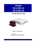
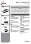
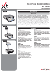
Figure 5
Model 764H-061 mounting hardware and electrical connections
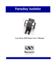
Figure 6
Model 764H-110 mounting hardware and electrical connections
14
5.3
Laser Diode Handling Precautions
CAUTION
Laser diodes are extremely sensitive to static discharge. The
manufacturer’s guidelines should be followed at all times when
handling laser diodes.
For a safe installation of the laser diode into the mount, please observe the following:
a. All operators must be properly grounded before handling any laser diode.
b. All related test and assembly equipment must be properly grounded.
Most laser diodes can only withstand a maximum reverse voltage of 2 to 3 volts across their
leads and no more than their maximum rated current in the forward direction. Always follow
the manufacturer’s instructions for removing and handling laser diodes.
It is recommended that the connection to the laser diode remain floating relative to Chassis
Ground (earth ground). This prevents AC transients or other voltage potentials arising from
multiple earth ground loops front, damaging the laser diode. Extreme care must be taken to
ensure that all devices including the laser diode driver, and any devices connected to the
laser diode, temperature controller, are all grounded to the same earth ground point.
If you have any questions on earth grounding a laser diode contact a Newport Applications
Engineer.
15
5.4
5.4.1
Laser Diode Mounting
Mounting the Laser Diodes and Wire Connection
The laser diode mount is provided with hole patterns from Oclaro’s select laser diode
families. For other laser diode hole patterns, the customer can order a spare top plate and
drill desired hole patterns.
Figure 7
Model 764H-110 mount (photo with special hole pattern on top plate)
CAUTION
Laser diodes are extremely sensitive to static discharge. The
manufacturer’s guidelines should be followed at all times when
handling laser diodes.
1. Carefully remove laser diode from packaging. Make certain you are properly grounded and
have proper anti-static work surface and environment at all times.
16
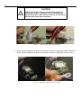
2. Use a SIL pad (if provided with a laser diode package) between the bottom surface of the
laser diode and the cold plate (mounting plate with the hole-pattern). If SIL pads are not
available, you may use thermal paste (AKA thermal grease). Apply the thermal paste
uniformly on the bottom surface of the laser diode module. Make sure there are no air
bubbles or areas without paste between the bottom surface of diode and the cold plate of the
LD mount. To clean excess thermal grease from around the laser diode, industrial grade
acetone and q-tips or Kim-wipes can be used.
Figure 8
SIL Pads for thermal coupling with cold plate
(Photo: the useful part of the SIL pad is in the metallic sheet between the white and pink
papers. Colors may vary.)
3. There are a few hole-patterns available on the LD mounting plates (cold plates). Depending
on which cold plate you have on your mount, various laser diodes can be accommodated.
Please refer to the appendix if you do not know which hole pattern to use for your specific
laser diode. If custom hole patterns are desired, one can carefully remove the top plate and
drill the desired holes. It is strongly recommended that the user purchase an extra top plate
(P/N 90032542 for 764H-110 and 90032541 for 764H-061) from Newport. Thermal
compound paste, required to enhance the thermal flow between the top plates, can be
purchased at a local hardware store or at Newport (P/N 05173-01).
17
Figure 9
Hole patterns on 764H-061 top plate for Oclaro’s Orion H2 and H3 package styles
CW / BW Series
Top Plate
Mounting Holes
Prosario Laser
Corvus Series
Orion Series
Figure 10
Hole patterns on 764H-110 top plate
4. Place the laser diode module onto the heat sink and gently tighten the screws onto the
mounting holes. Be careful not to damage the top-plate by applying too much force while
tightening the screws, if the screw bottoms out before the screw head reached the body of
the laser, do not tighten further and check screw length with the laser manufacturers. Verify
that the screws are of appropriate length.
18
CAUTION
Critical screw length - Improper mounting screw length can
damage the cold plate. If damage occurs, the mount will not
regulate temperature. Make sure the screws are not too long for
the laser diode/copper plate combination
Figure 11
Mounting screws for BWA series LD
5. Remove the shorting strip from the two electrodes on the back of diode module. Other laser
diodes may have alternate methods of shorting the terminals. (Photos for reference only).
Figure 12
BWA laser diode shown as an example
19
6. Connect the laser diode electrical cable (not supplied with mount) to the electrodes. Figure
9 shows example cable with the red wire connected to (+) and black wire connected to (-).
The specific cable used to connect the laser diode may vary depend on the laser diode and
LD driver used. Please see Newport’s website for available cable options. Contact the
laser diode manufacturers for recommended cable specifications. We recommend Newport’s
5700 Series High Power Laser Diode Drivers to supply input current to the laser diode.
Figure 13
LD wire connections
7. Make sure to connect the 24VDC adaptor to turn on the fan before supplying any current to
the diode module and TE Cooler on the mount.
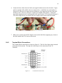
5.4.2
Terminal Block Connections
The Terminal block connections are shown in figure 10. The left of the figure shows internal
connections for the mount. The right side of the figure is the connections to the TE
Controller.
Figure 14
Terminal block connections
20
5.4.3
Temperature Controller Connection
The cable provided with the models 764H-061 and 764H-110 are designed to interface with
Newport models 3150 (obsolete) and 3700. The 764H-061 can also be used with 300B series
temperature controllers as well by using cable Model 300-02 and connecting the bare cable
ends to the mount. Make sure all the connections are securely tightened.
Figure 15
5.4.4
Pinout of cable for models 3150 and 3700
Laser Diode Driver Connection
High Power Laser diodes typically have two main connections for current, and some may
have a thermistor (or other sensor) connection. Therefore, most cable connection to the
laser diode consists of large diameter wires (rated for 40-80 Amps of current) with ring lugs
for connecting to the laser diode terminals (see previous section on mounting laser diode).
Newport offers various cables for connecting the laser diodes to the drivers. Contact
Newport Corporation or check on the website for the cable accessories available with each
type of laser diode driver.
5.5
General Operating Procedures
1. Securely mount the Model 764H Temperature Controlled Mount on an optical table by
using a post and post holder system not supplied with the mount.
2. After securing the mount, connect the cables of the temperature controller and the laser
diode driver to the mount.
3. Set the maximum TE module current on the temperature controller.
4. Set the current limit level on the laser diode driver and the desired drive current. Turn the
output of the laser diode driver on.
5. Allow the mount to stabilize its temperature which may take up to half an hour.
21
WARNING
Never look directly into the output aperture of laser diode at any
time. Laser Diodes emit invisible radiation that can cause
damage to the eyes. Also, take precautions to prevent specular
reflections from the laser diode’s output beam. Avoid exposure
at all times to laser emissions or collateral radiation in excess of
the applicable emission limits given in “Performance Standards
for Laser Products” United States Code of Federal Regulation,
21 CFR 1040.10(D)
22
6
Maintenance and Service
WARNING
There are no user serviceable parts inside the Model 764H
Temperature Controlled Laser Diode Mount. Work performed by
persons not authorized by Newport Corporation will void the
warranty.
6.1
Obtaining Service
The Model 764H series Temperature Controlled Laser Diode Mounts contains no user
serviceable parts. To obtain information regarding factory service, contact Newport
Corporation or your Newport representative. Please have the following information
available:
• Instrument model number (on the side of the unit)
• Instrument serial number (on the side of the unit)
• Description of the problem.
If the mount is to be returned to Newport Corporation, you will be given a Return Number,
which you should reference in your shipping documents. Please fill out a copy of the
service form, located on the following page, and have the information ready when
contacting Newport Corporation. Return the completed service form with the instrument.
23
6.2
Service Form
Newport Corporation
U.S.A. Office: 800-222-6440
FAX: 949/253-1479
Name _______________________________
(Please obtain RA# prior to return of item)
Return Authorization #__________________
Company ________________________________________________________________________
(Please obtain RA # prior to return of item)
Address ________________________________ ____________________Date _________________
Country _______________________ Phone Number ______________________________________
P.O. Number ___________________ FAX Number _______________________________________
Item(s) Being Returned:
Model # _______________________ Serial # __________________________
Description _______________________________________________________________________
Reason for return of goods (please list any specific problems):
24
7
Appendix
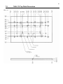
7.1
764H-061 Top Plate Dimensions
25
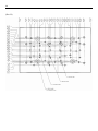
7.2
(Rev. A)
764H-110 Top Plate Dimensions
26
(Rev. B)