1
Smart Table ST-200
User’s Manual
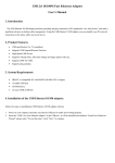
Preface
iii
Warranty
Newport Corporation warrants that this product will be free from defects in
material and workmanship and will comply with Newport’s published
specifications at the time of sale for a period of one year from date of
shipment. If found to be defective during the warranty period, the product
will either be repaired or replaced at Newport's option.
To exercise this warranty, write or call your local Newport office or
representative, or contact Newport headquarters in Irvine, California. You
will be given prompt assistance and return instructions. Send the product,
freight prepaid, to the indicated service facility. Repairs will be made and the
instrument returned freight prepaid. Repaired products are warranted for the
remainder of the original warranty period or 90 days, whichever first occurs.
Limitation of Warranty
The above warranties do not apply to products which have been repaired or
modified without Newport’s written approval, or products subjected to
unusual physical, thermal or electrical stress, improper installation, misuse,
abuse, accident or negligence in use, storage, transportation or handling. This
warranty also does not apply to fuses, batteries, or damage from battery
leakage.
THIS WARRANTY IS IN LIEU OF ALL OTHER WARRANTIES,
EXPRESSED OR IMPLIED, INCLUDING ANY IMPLIED WARRANTY
OF MERCHANTABILITY OR FITNESS FOR A PARTICULAR USE.
NEWPORT CORPORATION SHALL NOT BE LIABLE FOR ANY
INDIRECT, SPECIAL, OR CONSEQUENTIAL DAMAGES RESULTING
FROM THE PURCHASE OR USE OF ITS PRODUCTS.
First printing 2004
© 2004 by Newport Corporation, Irvine, CA. All rights reserved. No part of
this manual may be reproduced or copied without the prior written approval
of Newport Corporation.
This manual has been provided for information only and product
specifications are subject to change without notice. Any change will be
reflected in future printings.
Newport Corporation
1791 Deere Avenue
Irvine, CA, 92606
USA
Part No. 41399-01, Rev. B
iv
Preface
Confidentiality & Proprietary Rights
Reservation of Title:
The Newport programs and all materials furnished or produced in connection
with them ("Related Materials") contain trade secrets of Newport and are for
use only in the manner expressly permitted. Newport claims and reserves all
rights and benefits afforded under law in the Programs provided by Newport
Corporation.
Newport shall retain full ownership of Intellectual Property Rights in and to
all development, process, align or assembly technologies developed and other
derivative work that may be developed by Newport. Customer shall not
challenge, or cause any third party to challenge the rights of Newport.
Preservation of Secrecy and Confidentiality and Restrictions to Access:
Customer shall protect the Newport Programs and Related Materials as trade
secrets of Newport, and shall devote its best efforts to ensure that all its
personnel protect the Newport Programs as trade secrets of Newport
Corporation. Customer shall not at any time disclose Newport's trade secrets
to any other person, firm, organization, or employee that does not need
(consistent with Customer's right of use hereunder) to obtain access to the
Newport Programs and Related Materials. These restrictions shall not apply
to information (1) generally known to the public or obtainable from public
sources; (2) readily apparent from the keyboard operations, visual display, or
output reports of the Programs; 3) previously in the possession of Customer
or subsequently developed or acquired without reliance on the Newport
Programs; or (4) approved by Newport for release without restriction.
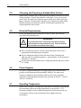
Service Information
This section contains information regarding factory service for the source.
The user should not attempt any maintenance or service of the system or
optional equipment beyond the procedures outlined in this manual. Any
problem that cannot be resolved should be referred to Newport Corporation.
Preface
v
Technical Support Contacts
North America & Asia
Newport Corporation Service Dept.
1791 Deere Ave. Irvine, CA 92606
Telephone: (949) 253-1694
Telephone: (800) 222-6440 x31694
Europe
Newport/MICRO-CONTROLE S.A.
Zone Industrielle
45340 Beaune la Rolande, FRANCE
Telephone: (33) 02 38 40 51 56
Newport Corporation Calling Procedure
If there are any defects in material or workmanship or a failure to meet
specifications, promptly notify Newport's Returns Department by calling 1-800-2226440 or by visiting our website at www.newport.com/returns within the warranty
period to obtain a Return Material Authorization Number (RMA#). Return the
product to Newport Corporation, freight prepaid, clearly marked with the RMA# and
we will either repair or replace it at our discretion. Newport is not responsible for
damage occurring in transit and is not obligated to accept products returned without
an RMA#.
E-mail: [email protected]
When calling Newport Corporation, please provide the customer care representative
with the following information:
•
•
•
Your Contact Information
Serial number or original order number
Description of problem (i.e., hardware or software)
To help our Technical Support Representatives diagnose your problem, please note the
following conditions:
•
•
•
•
Is the system used for manufacturing or research and development?
•
Can you identify anything that was different before this problem occurred?
What was the state of the system right before the problem?
Have you seen this problem before? If so, how often?
Can the system continue to operate with this problem? Or is the system nonoperational?
vi
Preface
Table of Contents
EU Declaration of Conformity............................................................... ii
Warranty................................................................................................ iii
Technical Support Contacts ................................................................... v
Table of Contents .................................................................................. vi
List of Figures ...................................................................................... vii
List of Tables ...................................................................................... viii
1
Safety Precautions
1.1
1.2
1.3
2
3
Definitions and Symbols .............................................................. 9
1.1.1
General Warning or Caution .............................................9
1.1.2 Electric Shock....................................................................9
1.1.3 CSA Mark with “C” and “US” Indicators.........................9
1.1.4 European Union CE Mark ...............................................10
1.1.5 Fuses ................................................................................10
1.1.6 Frame or Chassis .............................................................10
1.1.7 On ....................................................................................10
1.1.8
Off....................................................................................11
1.1.9 Protective Conductor Terminal .......................................11
1.1.10 USB Connector Symbol ..................................................11
1.1.11 Mounting precaution .......................................................11
Warnings and Cautions............................................................... 12
1.2.1 General Warnings............................................................12
1.2.2 General Cautions .............................................................13
Location of Warnings ................................................................. 13
1.3.1
Rear Panel........................................................................13
General Information
2.1
2.2
15
Introduction ................................................................................ 15
Specifications ............................................................................. 16
Getting Started
3.1
3.2
3.3
3.4
3.5
3.6
3.7
9
19
Unpacking and Handling............................................................ 19
Inspection for Damage ............................................................... 19
Parts List..................................................................................... 19
Choosing and Preparing a Suitable Work Surface ..................... 20
Electrical Requirements.............................................................. 20
Power Supplies ........................................................................... 20
Operating Temperature............................................................... 20
Preface
4
System Operation
4.1
4.2
5
25
Overview .................................................................................... 25
5.1.1 About Tab........................................................................26
5.1.2 Status Tab ........................................................................27
5.1.3 Auto -Tune Tab ...............................................................28
5.1.4 Manual Tune Tab ............................................................30
5.1.5 Options Tab .....................................................................31
Maintenance and Service
6.1
6.2
6.3
6.4
21
Front Panel.................................................................................. 21
4.1.1 AC Power Switch ............................................................21
4.1.2 Status ...............................................................................22
4.1.3 I/O....................................................................................22
4.1.4 Auto- Tune.......................................................................23
4.1.5 USB Interface ..................................................................23
Rear Panel................................................................................... 24
4.2.1 Damper Output connectors..............................................24
4.2.2 Frame or Chassis Terminal..............................................24
4.2.3 AC Power Inlet Socket ....................................................24
Software Application
5.1
6
vii
33
Enclosure Cleaning..................................................................... 33
Fuse Replacement....................................................................... 33
Obtaining Service ....................................................................... 34
Service Form .............................................................................. 35
List of Figures
Figure 1
Figure 2
Figure 3
Figure 4
Figure 5
Figure 6
Figure 7
Figure 8
Figure 9
Figure 10
Figure 11
Figure 12
General Warning or Caution Symbol............................................... 9
Electrical Shock Symbol .................................................................. 9
CSA mark with “C” and “US” Indicators ........................................ 9
CE Mark ......................................................................................... 10
Fuse Symbol................................................................................... 10
Frame or Chassis Terminal Symbol............................................... 10
On Symbol ..................................................................................... 10
Off Symbol..................................................................................... 11
Protective Conductor Terminal Symbol ........................................ 11
USB connector Symbol.................................................................. 11
Locations of warnings on the rear panel ........................................ 13
Typical Compliance Curve. ........................................................... 16
viii
Preface
Figure 13
Figure 14
Figure 15
Figure 16
Figure 17
Figure 18
Figure 19
Figure 20
Figure 21
Figure 22
Figure 23
Figure 24
Effect of damping on table vibration levels ................................... 17
Front Panel Layout......................................................................... 21
BNC output sensitivity................................................................... 23
Rear Panel ...................................................................................... 24
Smart Table-Util Software Icon ..................................................... 25
About Tab Screen........................................................................... 26
Status Tab Screen........................................................................... 27
Auto Tune Tab Screen showing dual-channel display................... 29
Auto Tune Tab Screen showing single-channel display ................ 29
Manual Tune Tab Screen ............................................................... 30
Options Tab Screen. ....................................................................... 32
Fuse Replacement .......................................................................... 34
List of Tables
Table 1
Table 2
Table 3
Table 4
Table 5
Specifications ................................................................................. 16
Smart Table Controller Specifications ........................................... 18
Envoronmental Specifications ....................................................... 18
Definition of SYSTEM, CH1 and CH2 status LED’s. .................. 22
Measurment Parameters ................................................................. 22
1
Safety Precautions
1.1
Definitions and Symbols
The following terms and symbols are used in this documentation and also
appear on the Smart Table Controller where safety-related issues occur.
1.1.1
General Warning or Caution
Figure 1
General Warning or Caution Symbol
The Exclamation Symbol in the figure above appears in Warning and Caution
tables throughout this document. This symbol designates an area where
personal injury or damage to the equipment is possible.
1.1.2
Electric Shock
Figure 2
Electrical Shock Symbol
The Electrical Shock Symbol in the figure above appears throughout this
manual. This symbol indicates a hazard arising from dangerous voltage.
Any mishandling could result in irreparable damage to the equipment, and
personal injury or death.
1.1.3
CSA Mark with “C” and “US” Indicators
Figure 3
CSA mark with “C” and “US” Indicators
The presence of the CSA mark with “C” and “US” indicates that it has been
designed, tested and certified as complying with all applicable U.S. and
Canadian safety standards.
9
10
Safety Precautions
1.1.4
European Union CE Mark
Figure 4
CE Mark
The presence of the CE Mark on Newport Corporation equipment means that
it has been designed, tested and certified as complying with all applicable
European Union (CE) regulations and recommendations.
1.1.5
Fuses
Figure 5
Fuse Symbol
The fuse symbol in the figure above identifies the fuse location on the Smart
Table Controller.
1.1.6
Frame or Chassis
Figure 6
Frame or Chassis Terminal Symbol
The symbol in the figure above appears on the Smart Table Controller. This
symbol identifies the frame or chassis terminal.
1.1.7
On
Figure 7
On Symbol
The On Symbol in the figure above represents a power switch position on on
the Model ST-200 Smart Table controller. This symbol represents a Power
On condition.
Safety Precautions
1.1.8
11
Off
Figure 8
Off Symbol
The Off Symbol in the figure above represents a power switch position on the
Model ST-200 Smart Table controller. This symbol represents a Power Off
condition.
1.1.9
Protective Conductor Terminal
Figure 9
Protective Conductor Terminal Symbol
The protective conductor terminal symbol in the above figure identifies the
location of the bonding terminal, which is bonded to conductive accessible
parts of the enclosure for safety purposes. The intent is to connect it to an
external protective earthing system through the power cord.
1.1.10
USB Connector Symbol
Figure 10
USB connector Symbol
The USB connector symbol in the above figure identifies the location of the
USB communications connector.
1.1.11
Mounting precaution
The dampers are installed at two corners of the table adjacent to a long side.
The exact position of each damper is indicated by three flat-head screws
visible flash with the table top. Please have in mind that four sealed holes in
each damper area are only 0.457 in (11.6 mm) deep. If you need to use some
of these holes, choose the length of the screws accordingly. An attempt to use
too long screws may cause damage to the dampers and de-lamination of the
table face sheet.
12
Safety Precautions
1.2
Warnings and Cautions
The following are definitions of the Warnings, Cautions and Notes that are
used throughout this manual to call your attention to important information
regarding your safety, the safety and preservation of your equipment or an
important tip.
WARNING
Situation has the potential to cause bodily harm or death.
CAUTION
Situation has the potential to cause damage to property or
equipment.
NOTE
Additional information the user or operator should consider.
1.2.1
General Warnings
Observe these general warnings when operating or servicing this equipment:
• Heed all warnings on the unit and in the operating instructions.
• Do not use this equipment in or near water.
• This equipment is grounded through the grounding conductor of the power
•
•
•
•
•
cord.
Route power cords and other cables so they are not likely to be damaged.
Disconnect power before cleaning the equipment. Do not use liquid or
aerosol cleaners; use only a damp lint-free cloth.
To avoid fire hazard, use only the specified fuse(s) with the correct type
number, voltage and current ratings as referenced in the appropriate
locations in the service instructions or on the equipment. Only qualified
service personnel should replace fuses.
To avoid explosion, do not operate this equipment in an explosive
atmosphere.
Qualified service personnel should perform safety checks after any
service.
Safety Precautions
1.2.2
13
General Cautions
Observe these cautions when operating or servicing this equipment:
• If this equipment is used in a manner not specified in this manual, the
•
•
•
•
•
•
•
protection provided by this equipment may be impaired.
To prevent damage to equipment when replacing fuses, locate and correct
the problem that caused the fuse to blow before re-applying power.
Do not block ventilation openings.
Use only the specified replacement parts.
Follow precautions for static sensitive devices when handling this
equipment.
This product should only be powered as described in the manual.
There are no user-serviceable parts inside the ST-200 Smart Table
Controller.
To prevent damage to the equipment, read the instructions in the
equipment manual for proper input voltage.
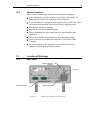
1.3
Location of Warnings
1.3.1
Rear Panel
Frame or Chassis
Terminal
Fuse info
MAX Power
Electrical Hazard
Figure 11
Locations of warnings on the rear panel
14
Safety Precautions
This page is intentionally left blank
2
General Information
2.1
Introduction
The Smart Table is a combination of the structurally damped vibration
isolation table with electronics that can monitor vibration in real time and
active elements that use the vibration data to suppress the vibration.
Vibration state of the optical table is an important characteristic, in many
cases defining its suitability for a task at hand. Reducing vibration, especially
the dynamic deviation of the table from a rigid-body type behavior, is one of
the most important criterions of the table design. It is achieved mainly by the
vibration isolation. Vibration isolation by passive isolating legs, such as
Newport I-2000, reduces the vibration transmitted to the table from the floor.
Although excellent isolation from floor vibration can be achieved in these
systems, the table will deviate from the ideal rigid-body behavior at natural
frequencies of its flexural vibrations. External sources acting on the tabletop
(air turbulence or acoustical waves) or the dynamic events generated in the
payload excite resonance vibration in the table’s own free-state modes such
as bending and torsion. This can lead to deterioration of the payload
performance, in particular, misalignment of the optical equipment.
The Smart Table includes two active vibration dampers that add dissipation
to all natural vibration modes of the table in a wide frequency range without
creating any additional resonances at lower frequencies. If the load on the
table changes, the dampers maintain their efficiency and stability after simple
auto-tuning of control gains.
15
16
General Information
2.2
Specifications
Working Surface
400 Series ferromagnetic stainless steel
3/16 in. (4.8 mm) thick with integrated damping layer
Surface Flatness
[in. (mm)]
±0.004 (±0.1), over 2 ft. (600 mm) square
Core Design
Trussed honeycomb, vertically bonded closed cell construction,
0.010 in. (0.25 mm)
Steel sheet materials, 0.030 in. (0.76 mm) Triple core interface
Active Damping
Adjustable electronic dampers
Structural Damping
Constrained layer core, damped working surface and
composite edge finish
Mounting Holes
1/4-20 holes on 1 in. grid (M6-1.0 holes on 25 mm grid), 0.5 in.
borders (12.5 mm borders)
Hole/Core Sealing
Easy clean conical cup 0.75 in. (19 mm) deep,
Non-corrosive high impact polymer material
Typical Table Performance Values
ST Series
Maximum Dynamic Deflection Coefficient
0.4 x 10⁻³
Maximum Relative Motion Value [in. (mm)]*
<3.0 x 10⁻⁹ (<7.6 x 10⁻⁸)
Deflection Under Load [in. (mm)]†
<5.0 x 10⁻⁵ (<1.3 x 10⁻³)
Table 1
Specifications
Compliance, in/lb, damped corner
1 .10
3
1 .10
4
1 .10
5
1 .10
6
1 .10
7
10
100
Hz
1 .10
3
ON
OFF
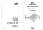
Figure 12
Typical Compliance Curve.
(This data was taken on a ST-48-8 table supported by I-2000 isolators.)
General Information
17
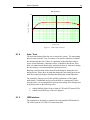
Vibration linear spectrum 25 cm from edges near an instrumented corner
2
Displacement, nm
1.5
1
0.5
0
50
100
150
200
250
Frequency, Hz
300
350
400
450
Damping ON
Damping OFF
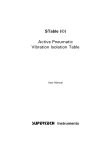
Figure 13
Effect of damping on table vibration levels
The Smart Table uses the same materials and has the same main mechanical
characeristics as passively damped Newport RS series table. The dampers are
installed at two corners of the table adjacent to a long side. The exact position
of each damper is indicated by three flat-head screws that are flash with the
table top at the corners.
CAUTION
Please keep in mind that four sealed threaded holes in each
damper area are only 0.457 in (11.6 mm) deep. If you need to use
some of these holes, choose the length of the screws
accordingly. An attempt to use too long screws may cause
damage to the dampers and de-lamination of the table face sheet.
18
General Information
Smart Table Controller Specifications
Output Power
Continuous current
0.4A @ 12VDC
Output Voltage
Maximum effective output voltage at continuous power
@ 12V @ 0.4A
Input Power
Voltage
Average Current @ continuous output rating
Peak Current @ continuous output rating
12V ±5%
0.6A
0.7A
Table 2
Smart Table Controller Specifications
System Environmental Specifications
AC Input
100-240VAC ±10%
47-63Hz,
1.25A, 80W
Operating Temperature
5°C to 40°C
Operating Humidity
<85% relative humidity non-condensing
Storage Temperature
0-60°C
RH - <85% non-condensing
Altitude
<3000
Electrical Class
1
Installation Category
2
Pollution Degree
2
Use Location
Indoor use only
Table 3
Envoronmental Specifications
3
Getting Started
3.1
Unpacking and Handling
It is recommended that the Smart Table Controller is unpacked in a lab
environment or work site. Unpack the system carefully; small parts and
cables are included with the instrument. Inspect the box carefully for loose
parts before disposing of the packaging. You are urged to save the packaging
material in case you need to ship your equipment in the future.
3.2
Inspection for Damage
The Smart Table Controller is carefully packaged at the factory to minimize
the possibility of damage during shipping. Inspect the box for external signs
of damage or mishandling. Inspect the contents for damage. If there is
visible damage to the instrument upon receipt, inform the shipping company
and Newport Corporation immediately.
WARNING
Do not attempt to operate this equipment if there is evidence of
shipping damage or you suspect the unit is damaged. Damaged
equipment may present additional hazards to you. Contact
Newport technical support for advice before attempting to plug
in and operate damaged equipment.
3.3
Parts List
The following is a list of parts included with the Smart Table System.
1. ST Series table with dampers already installed inside table
2. ST-200 Controller
3. Two 15 pin damper cables
4. Power cord
5. User’s Manual
If you are missing any hardware or have questions about the hardware you
have received, please contact Newport.
19
20
Getting Started
3.4
Choosing and Preparing a Suitable Work Surface
Smart Table Controller may be placed on any reasonably firm table or bench
during operation. Position the controller so that there is easy access to the
power cord. The front legs of the unit can be pulled out to tilt the unit at an
angle, if desired. Do not put the Controller on or attach to the isolated table.
Manual operation of front panel controls will disturb mechanically the
normal operation of the system.
3.5
Electrical Requirements
Before attempting to power up the unit for the first time, the following
precautions must be followed:
WARNING
To avoid electric shock, connect the instrument to properly
earth-grounded, 3-prong receptacles only. Failure to observe
this precaution can result in severe injury.
• Have a qualified electrician verify the wall socket that will be used is
properly polarized and properly grounded.
• Provide adequate distance between the Smart Table Controller and
adjacent walls for ventilation purposes. Approximately 2-inch spacing for
all surfaces is adequate.
• Set the mains selector tumbler to the voltage that matches the power outlet
AC voltage.
3.6
Power Supplies
AC power is supplied through the rear panel input power connector that
provides in-line transient protection and RF filtering. The input power
connector contains the fuses and the switch to select series or parallel
connection of the transformer primaries for operation at 100VAC, 120VAC,
220VAC or 240VAC.
3.7
Operating Temperature
Smart Table Controller is designed for operation in a laboratory environment.
Recommended ambient operating temperatures are between 20 - 25°C.
Operation at higher or lower ambient temperatures for limited periods (e.g.
several hours) will not cause any harm but may slightly reduce the
performance.
4
System Operation
WARNING
Before operating the Model Smart Table Series, please read and
understand all of Section 1.
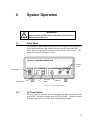
4.1
Front Panel
The front panel of the Smart Table Controller is arranged for easy operation.
Seven distinct indicators and controls are located on the front panel that
allows the user to operate the system as well as provide system status. The
front panel is shown in Figure 14 below.
Outputs 1
and 2
Power Switch
Auto-Tune
Button
Status LEDs
Figure 14
4.1.1
USB Port
Front Panel Layout.
AC Power Switch
When AC power is turned on the unit starts up in a default configuration with
the OUTPUT off and the display in the SETPOINT mode. The power switch
is located in the lower left corner of the instrument front panel.
21
22
System Operation
4.1.2
Status
The table below shows the meaning of the various colors of SYSTEM, CH1
and CH2 status LED’s.
Item
1
2
3
4
5
6
7
8
9
10
11
12
13
14
15
16
17
18
19
20
Level
Category
Comment
System
Unpowered AC not connected or Power Switch off
System
Unpowered Blown fuse
System
Unpowered Defective power supply
System
Powered Controller performing self-check
System
Powered No system problem
Controller firmware non-functional
System
Fault
Damper
not connected
Channel 1
Fault
Channel shutdown due to 'Damper Fault'
Channel 1
Fault
Channel 1
Fault
Channel shutdown due to 'Payload Change'
Channel 1
Warning Channel operating in 'overload' condition
Channel 1
Tuning
Auto-tuning in process
Channel 1 Damping Normal operation
Channel 1 Disabled Channel shutdown via software
Damper not connected
Channel 2
Fault
Channel shutdown due to 'Damper Fault'
Channel 2
Fault
Channel 2
Fault
Channel shutdown due to 'Payload Change'
Channel 2
Warning Channel operating in 'overload' condition
Channel 2
Tuning
Auto-tuning in process
Channel 2 Damping Normal operation
Channel 2 Disabled Channel shutdown via software
Table 4
4.1.3
Ch1
LED
OFF
OFF
OFF
RED
B-RED
B-AMBER
AMBER
B-GREEN
GREEN
OFF
-
Ch2
LED
OFF
OFF
OFF
RED
B-RED
B-AMBER
AMBER
B-GREEN
GREEN
OFF
System
LED
OFF
OFF
OFF
AMBER
GREEN
RED
GREEN
GREEN
GREEN
GREEN
GREEN
GREEN
GREEN
GREEN
GREEN
GREEN
GREEN
GREEN
GREEN
GREEN
Definition of SYSTEM, CH1 and CH2 status LED’s.
I/O
The vibration can be monitored independently by connecting signal
processing equipment such as a signal analyzer or an oscilloscope to the BNC
jacks on the front panel of the controller. The measurement parameters are
listed in Table 5 below.
Measurement parameters
Sensitivity
30 V/(mm/s)
Measurement range (0 – p)
0.16 mm/s
Frequency range (-3 dB)
18 Hz to 820 Hz
Table 5
Measurment Parameters
± 12%
System Operation
23
BNC sensitivity
Sensitivity, V/(mm/s)
100
10
1
10
100
Frequency, Hz
Figure 15
4.1.4
3
1 .10
BNC output sensitivity
Auto- Tune
The auto-tune button allows the user to retune the system. The auto-tuning
process takes normally 30 to 40 seconds. Care must be taken not to disturb
the table during this time. If there is equipment on the table that can be a
source of non-stationary vibration or noise, it should be shut down. If the
table was inadvertently disturbed by mechanical shock or loud noise during
the auto-tuning, it is recommended to repeat the process.
Beeping or tonal sounds can be heard from the dampers during the autotuning process. Please have in mind that during the auto-tuning process the
table may experience higher vibrations that during the normal operation.
The controller comes pre-set for the optimal performance of the lightly
loaded table. If additional load is put on the table or, subsequently, taken
from the table, it is recommended to perform auto-tuning. Auto-tuning must
be performed also in the following cases:
•
•
4.1.5
Amber blinking lights of one or both of CH1 and CH2 status LEDs.
Audible sound from any of the two dampers.
USB Interface
The instrument is designed to communicate with standard USB interfaces.
The cable required is a USB A/ B connection cable.
24
System Operation
NOTE
With critical applications the radio frequency emissions, while using the USB cable,
may be reduced by routing the USB cable through one or more ferrite cores, such as
the Fair-Rite Products Corporation part number # 0443164251."
4.2
Rear Panel
The Smart Table Controller rear panel shows the OUTPUT connectors and
the AC power inlet.
CSA
Label
CE
Label
Frame or Chassis
Terminal
Voltage
setting
Fuse
Model
Number
Label
Channel 2
Damper Output
Connector
Channel 1
Damper Output
Connector
Figure 16
4.2.1
Rear Panel
Damper Output connectors
Two 15- pin connectors labeled CH1 and CH2 are the connection points for
the Smart Table active dampers
4.2.2
Frame or Chassis Terminal
This terminal provides access to frame or chassis connection.
4.2.3
AC Power Inlet Socket
Plug the included power cord into the Power Inlet Socket on the rear of the
instrument, then plug the power cord into a wall socket with proper earth
grounding.
5
Software Application
5.1
Overview
Provided on the CD that comes with the Smart Table Controller is an installation
package for SmartTable-Util application and USB drivers. This application
communicates with the Smart Table Controller through USB communication
interface. The application is designed to allow the user to remotely control all
the features supported by the controller.
Figure 17
Smart Table-Util Software Icon
NOTE
Install the software and USB drivers before connecting
USB cable to the controller for the first time.
1. Minimum requirements for the computer are:
•
•
•
•
•
•
•
•
A personal computer with a 486DX or higher processor
Microsoft Windows 98 operating system or Microsoft Windows
2000/XP operating system
64 MB of memory for Windows
10 MB of hard disk space
USB port (version 1.1 minimum)
VGA or higher-resolution video adapter
Microsoft Mouse or compatible pointing device
CD-ROM drive (for installation only)
1. Place the CD that accompanies the controller in your CD-ROM drive.
Installation of the SmartTable-Util application and USB drivers will start
automatically. If it does not start, initiate installation by double-clicking
on the SETUP.EXE file in the CD.
25
26
Software Application
2. Connect the USB cable to the Controller and Power it on.
3. Start the application by double-clicking on the newly created Smart
Table-Util icon in Start->Programs->Newport->Smart Table Controller
folder.
The SmartTable-Util application has five (5) main tabs: About, Status, Autotune, Manual Tune and Options. The features available in these tabs are
explained in the following sub-sections.
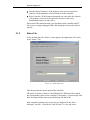
5.1.1
About Tab
When the application is opened, it will default to the “About” tab. It will
also start communication with the controller connected to USB interface.
The application and controller firmware version numbers are displayed on
this screen.
Software and
Firmware Versions
Smart Table
Utility Function
Tabs
Bottom Bar is
common to all the
screens
Mouse over some
buttons will reveal
Tool Tips for ease
of use
Figure 18
About Tab Screen
Click on “Firmware Download” button to update the controller’s firmware.
The software will prompt the user to select a “DSP Firmware File at the
beginning of the firmware download process”. This file has an “FWR”
extension, and is located in the Firmware subdirectory by default. Once this
file is selected, the application will initiate the download process. This
process consists of the following steps:
• Erase Firmware: At this stage, the controller’s existing firmware is erased
from its non-volatile flash memory.
Software Application
• Download New Firmware: If the firmware erase was successful, the
software will download the selected firmware to the controller.
• Reset Controller: If the firmware download was successful, the software
will perform a soft reset of the controller in order for the newly
downloaded firmware to take affect.
Ensure that USB communication is not lost between the controller and PC
due to power outage/unplugged USB cable during the firmware download
process.
5.1.2
Status Tab
A few seconds after the “About” screen appears, the application will switch
to the “Status” Tab.
Figure 19
Status Tab Screen
This tab provides the current status of the controller.
The status of System, Channel #1 and Channel #2 LEDs shown here match
the corresponding values on the controller’s front-panel. A text message with
brief description of the status is provided along side the LEDs.
If the controller generates any errors, they are displayed in the “Error
Messages” text box. Click on the “Last 10 Errors” to view old errors.
28
Software Application
5.1.3
Auto -Tune Tab
This tab provides access to initiating the auto-tuning process remotely, as
well as to observe the controller performance.
Adjust the control loop gain stability margin to a desired level (low, medium
or high) and click on “Auto-Tune” button. Clicking on the “Auto-Tune”
button here is similar to pushing “Auto-Tune” button on the controller’s
front-panel, with added control over the control loop gain stability margin.
The controller uses “medium” stability setting when auto-tuning process is
started locally.
Clicking on “Enable Damping” or “Disable Damping” buttons to will enable
or disable damping. If the damping is enabled, the “Disable Damping” button
is visible, and vice versa.
Click on “Measure Un-damped Vibration Level” button to record vibration
level with damping disabled. The software will disable damping on both
channels and measure vibration levels over a period of 500ms. The data will
be averaged over several time frames. Number of averages can be set on the
“Options” tab (Section 5.1.5.2)
Click on “Measure Damped Vibration Level” button to record vibration level
with damping enabled. The software will enable damping on both channels
and measure vibration levels over a period of 500ms. The data will be
averaged over several time frames. Number of averages can be set on the
“Options” tab (Section 5.1.5.2)
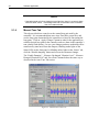
Both un-damped and damped vibration level data can be displayed in either
frequency domain or time domain. Select either FFT or Time Resp. from the
pull-down menu for desired view. The FFT resolution is 2 Hz. The software
also provides access to viewing the measurements for only one channel or
both channels. Check the “Show Graph” box for showing either singlechannel or dual-channel display.
Click on “Save Data” button to save the measured data. If “HTML” file
option is selected in the “Options” tab, all the graphs are saved in the form of
a report in HTML file format.
If “Text” file option is selected in the “Options” tab, the measured data will
be saved in two (2) files: one for time response data, and the other for
frequency response data. Users will be prompted to select desired filenames
for these files. The time response file contains five (5) columns in the
following order: time stamp, damped data for channel #1, un-damped data for
channel #1, damped data for channel #2, un-damped data for channel #2.
The frequency response file contains five (5) columns in the following order:
frequency bins, damped data for channel #1, un-damped data for channel #1,
damped data for channel #2, un-damped data for channel #2.
Software Application
Figure 20
Figure 21
Auto Tune Tab Screen showing dual-channel display
Auto Tune Tab Screen showing single-channel display
30
Software Application
NOTE
If the background color for a window is set to light blue, then it is a control, where
users can enter values. If the background color for a window is set to off-white,
then it is a status window.
5.1.4
Manual Tune Tab
This tab provides direct control over the control loop gain used by the
controller. It is recommended that users Auto-Tune their system first, and
use the loop gains determined by the controller as a basis for fine-tuning the
loop gains. Click on “Apply Changes” button in order for the application to
send the desired loop gains to the controller, and save them in the controller’s
non-volatile flash memory. In case your changes produces undesirable effect
manifested by tonal noise from the dampers, blinking amber lights of the
Status LEDs on the front panel, or blinking amber lights on the “Status” tab,
click the “Disable damping” button and reverse the erroneous changes
The “Enable Damping”, “Measure Un-damped Vibration Level”, “Measure
Damped Vibration Level” and “Save Data” buttons behave the same way as
described in the Auto-Tune Tab section.
Figure 22
Manual Tune Tab Screen
Software Application
NOTE
“Apply Changes” button needs to be pushed every time the settings are changed, so
that the changes can be sent to the controller.
After examining the damped vs. un-damped vibration levels, if the users find
some undesirable amplified resonance peak, that peak can be reduced by
enabling the optional notch filter. Check the “Enable Notch Filter” box,
specify the desired frequency and click on “Apply Changes” button. Note
that selecting this option can destabilize the controller depending upon the
notch frequency. Click the “Disable damping” button and reverse the
erroneous changes to return to stable work.
5.1.5
Options Tab
The Options Tab allows the user to customize the controller and the
SmartTable-Util functionality to their requirement. It provides access to the
following:
5.1.5.1
Auto-tuning
• Enable the front panel switch: Uncheck this box to disable initiation of
auto-tuning process locally.
• Low, Medium and High control loop gain margins: Specify the desired
percentage by which control loop gain has to be reduced at the end of
auto-tuning process. The gain stability margin and the control loop gain
determined by the controller have inverse relation. While lower loop gain
may be desired if the system is being used in an environment where the
payload is continuously changing, such lower gain will also result in
reduced damping performance.
5.1.5.2
Data Acquisition
• Enable FFT averaging: Uncheck this box to cancel averaging by the
application. If this box is not checked, the application will collect undamped or damped vibration levels only once.
• Number of averages: Specify the number of times un-damped damped
vibration levels have to be collected, and the FFT has to be averaged.
5.1.5.3
Monitoring & Diagnostics
• Payload change detection: Uncheck this box to prevent the controller
from detecting changes in the Smart Table payload that might necessitate
tuning of control loop gains.
• Feedback overload detection: Uncheck this box to prevent the controller
form monitoring the ambient vibration levels.
32
Software Application
• Overload duration: If feedback overload detection is enabled, specify the
amount of time for which feedback signal overload is allowed before the
controller generates a warning message.
• Enable auto-ranging. Uncheck this box if you do not want the preamplifier gains adjust to vibration environment. The box should be
unchecked if the payload operation involves high vibration levels for short
periods of time.
5.1.5.4
Miscellaneous
• Click on “Apply Settings” button in order for the application to send any
changes made on this tab to the controller.
• Click on “Save Settings to File” button to save the controller’s settings to
a file on user’s PC.
• Click on “Restore Settings from File” button to restore the controller’s
settings from a file on user’s PC.
• Click on “Restore Default Settings” button to restore the controller’s
settings to default values.
Figure 23
Options Tab Screen.
6
Maintenance and Service
CAUTION
There are no user serviceable parts inside the Smart Table
Controller. Work performed by persons not authorized by
Newport Corporation will void the warranty.
6.1
Enclosure Cleaning
WARNING
Before cleaning the enclosure of the Smart Table Controller, the
AC power cord must be disconnected from the wall socket.
The enclosure may be cleaned with a soft cloth dampened with either a mild
soapy water solution or Isopropyl Alcohol. Do not use any other chemicals or
solutions. Danger: Flammable cleaning liquid- avoid sources of
ignition and clean in well ventilated area.
6.2
Fuse Replacement
Pry open cover to
remove fuses
33
34
Maintenance and Service
Figure 24
Fuse Replacement
WARNING
To reduce the risk of electric shock or damage to the instrument,
turn the power switch off and disconnect the power cord before
replacing a fuse.
If a fuse blows:
1. Disconnect the power cord from the controller
2. Pry out the fuse cover and remove the fuse holders.
3. Replace the fuse(s).
Use only 5 * 20mm time lag fuses as indicated below
Fuse Replacement
1.25Amp, (T), 250V
4. Reconnect the power cord and turn on the instrument.
5. If the problem persists, contact Newport Corporation for service.
6.3
Obtaining Service
The Smart Table Controller contains no user serviceable parts. To obtain
information regarding factory service, contact Newport Corporation or your
Newport representative. Please have the following information available:
1. Instrument model number (on the rear panel)
2. Instrument serial number (on rear panel)
3. Description of the problem.
If the instrument is to be returned to Newport Corporation, you will be given
a Return Number, which you should reference in your shipping documents.
Please fill out a copy of the service form, located on the following page, and
have the information ready when contacting Newport Corporation. Return
the completed service form with the instrument.
Maintenance and Service
6.4
Service Form
Newport Corporation
U.S.A. Office: 800-222-6440
FAX: 949/253-1479
Name _______________________________
Return Authorization #__________________
(Please obtain RA# prior to return of item)
Company ________________________________________________________________________
(Please obtain RA # prior to return of item)
Address ________________________________ ____________________Date _________________
Country _______________________ Phone Number ______________________________________
P.O. Number ___________________ FAX Number _______________________________________
Item(s) Being Returned:
Model # _______________________ Serial # __________________________
Description _______________________________________________________________________
Reason for return of goods (please list any specific problems):
Newport Corporation
Worldwide Headquarters
1791 Deere Avenue
Irvine, CA 92606
(In U.S.): 800-222-6440
Tel: 949-863-3144
Fax: 949-253-1680
Internet: [email protected]
Visit Newport Online at: www.newport.com