1
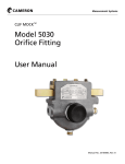
MODEL 199
DIFFERENTIAL PRESSURE UNIT (DPU)
Standard and NACE Service
User Manual
Manual No. 9A-10030, Rev. 01
January 2008
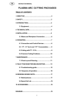
CONTENTS
Section 1 - Introduction................................................................... Page 3
Section 2 - Theory of Operation..................................................... Page 5
Section 3 - Installation/Operation ................................................. Page 9
Section 4 - Maintenance, Adjustment, & Calibration.................. Page 13
4-1. Tools Required for Maintenance and Calibration.............. Page 13
4-2. DPU Inspection and Cleaning............................................. Page 13
4-3. Calibration Setup................................................................... Page 18
4-4. Torque Tube Rotation Check (Replacement Units).......... Page 18
4-5. Range Change........................................................................ Page 19
4-6. Setting Bellows Travel........................................................... Page 22
4-7. Bellows Unit Assembly (BUA) Replacement..................... Page 22
4-8. Attaching Drive Arm to Torque Tube.................................. Page 24
4-9. Drive Arm Tightness Test..................................................... Page 24
4-10. Adjusting Pulsation Dampener.......................................... Page 25
4-11. Troubleshooting................................................................... Page 25
Section 5 - Parts Drawing/List........................................................ Page 27
Section 6 - Outline Dimension Drawings...................................... Page 30
(This manual is for the DPU only.) Refer to the appropriate (separate)
instrument manual for information on the instrument being actuated.
Barton instrument is as stated on the back (last
SECTION 1 - INTRODUCTION
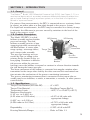
1-1. General
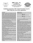
The Barton® Model 199 Differential Pressure Unit (DPU) (see Figure 1 -1) is a
mechanical device which accurately measures differential pressure relative to a
gas or liquid flowing through a process system, or to the level of a liquid con
tained in a process vessel.
For process flow measurements, the DPU is connected across a primary device
(a venturi, an orifice plate or a flow tube) located in the process system.
For liquid level measurements, the DPU may be connected in a variety of ways
to measure the difference in pressure caused by variations in the level of the
liquid in the process vessel.
1-2. Product Description
The Model 199 DPU is a dual
HP Housing
LP Housing
bellows assembly enclosed within
pressure housings. The dual
bellows assembly consists of two
opposing internally connected liqVenting
uid-filled bellows, a center plate,
Connection
range springs, overrange valves, Torque Tube
Shaft
and a torque tube assembly.
The pressure housings are conPressure
nected by Pipe or tubing to the
Connection
primary device located in the sysMounting
tem piping. Variations in differenBracket
tial pressure within the pressure
housings cause the bellows to expand or contract in a linear direction towards
the side having the lowest pressure.
The linear movement of the bellows is converted into angular rotation when
transmitted to the torque tube shaft by the drive arm and this mechanical motion actuates the mechanism of the process monitoring instrument.
The process monitoring instrument that is connected to the torque tube assembly may be an indicator, a switch, a transmitter, a recorder, or other process
control device.
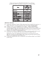
1-3. Specifications
Torque Tube Rotation (full scale DP).............8° ±10%
Torque Tube Material..................................Beryllium Copper (BeCu)
Temperature Limits ....................................-40°F/°C to +180°F (+82°C)
Maximum Non-linearity:
0-10" w.c. to 0-400" w.c.
(0-25 mbar to 0-993 mbar) .........................±0.5% of full scale with
appropriate linkage
0-401" w.c. to 0-100 psi
(0-996 mbar to 0-6.9 bar) ...........................±0.75% of full scale with
appropriate linkage
Repeatability ..............................................0.20% of full scale DP
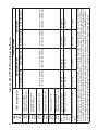
Housing Materials/Ranges ..........................Refer to Table 1-1
3
4
Forged Alloy Steel 4142
Forged Stainless Steel 17-4 PH
6,000
(414)
0.5" (8.2 cc)
1.5" (25 cc)
26" (425 cc)
30" (490 cc)
0-10" w.c. to 0-400" w.c.
(0-25 mbar to 0-993 mbar)
0.5" (8.2 cc)
31" (510 cc)
35" (575 cc)
0-15 psi to 0-100 psi
(0-1 bar to 0-6.9 bar)
1.5" (25 cc)
26" (425 cc)
30" (490 cc)
0-10" w.c. to 0-400" w.c.
(0-25 mbar to 0-993 mbar)
NOTES: Zero center or split ranges available on special order (e.g., 0-50" w.c. (0-124 mbar) range may be ordered 25-0-25" w.c. (62-0-62 mbar) or 100-40" w.c. (25-0-99 mbar). Intermediate DP ranges available from 0-20" w.c. to 0-100 psi (0-50 mbar ot 0-6.9 bar). Other sizes and types of connectuions (welding stubs, MS, A.N.D., etc.) available upon request. Standard pressure connections are 1/2" (top) and 1/4" (bottom) NPT. Range springs are
not interchangeable between the different size bellows, the inconel bellows, or the 10" w.c. (25 mbar) range. 3,000, 4,500, and 6,000 SWP versions
can be specified to meet NACE MR-01-75 (Rev. 80). Metric conversions are approximate. Outline dimension drawings available upon request.
Displacement in cu. in.(cc) for full-scale
travel
31" (510 cc)
Forged Alloy Steel 4142
4,500
(310)
35" (575 cc)
Forged Stainless Steel 316
3,000
(207)
0-15 psi to 0-100 psi
(0-1 bar to 0-6.9 bar)
High Pressure (HP) Head
Forged Steel AISI C1018
2,500
(172)
3-3/4" (95mm) O.D.
Inconel Bellows
2-1/8" (55mm) O.D.
Available DP Ranges
3-3/4" (95mm) O.D.
Stainless Steel Bellows
2-1/8" (55mm) O.D.
Low Pressure (LP) Head
Forged Steel AISI C1018
(For NACE Service)
NACE
2,000
(138)
Net
Volume
in cu. in.
(cc)
Cast Aluminum 356T6
Forged Stainless Steel 316
Body Housing Material
1,000
(69)
SWP
psi
(bar)
Table 1-1. Model 199 DPU Material/Range Specifications
SECTION 2 - THEORY OF OPERATION
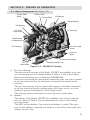
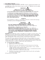
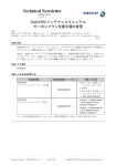
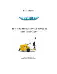
2-1. Basic Components (See Figure 2-1)
Torque Tube
Shaft
Center Plate
Torque Tube
LP Bellows
Range Spring
HP Bellows
HP Overrange Valve
LP Housing
Temperature
Compensator
LP Overrange
Valve
HP Housing
Housing
Bolts
Pulsation Damper
Valve Stem
Damping Valve Plug
Figure 2-1. 199 BUA Cutaway
A. Pressure Housings
The two pressure housings of the Model 199 DPU are available in the various safe working pressure ratings defined in Table 1-1 and in the Outline
Dimensional Drawings (seen in Section 6 DRAWINGS).
Each pressure housing has two tapped connection ports: one port is located
in the top of the housing, the other port is located in the bottom of the
housing.
The pressure housings may be rotated 180 degrees to facilitate connection
at the top of the housing for draining when used in gas service, or at the
bottom to provide venting when used in liquid service.
The housings enclose the bellows on each side of the center plate.
B. Bellows
The bellows of the Model 199 DPU are available in the various materials
and sizes (refer to Table 1-1) to accommodate the various safe working
pressure ratings.
The DPU has two bellows. One end of each bellows is sealed. The open
end of each bellows is attached and sealed to a side of the center plate (one
bellows on each side).
5
The bellows and center plate are filled with fill liquid via the drive arm hole
plug. An opening through the center plate provides a passageway for the
transfer of fill liquid between the two bellows. This opening also allows the
bellows to be connected internally by a valve stem.
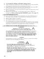
C. Range Springs
The range of the dual-bellows type DPU is determined by the force required
to move the bellows through their normal range of travel.
The range springs, which are available in various ranges (refer to
Table 1-1), act with the bellows and torque tube to balance the differential
pressure applied to the unit. The number of springs used and their spring
rate depends on the individual differential pressure range requirement.
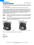
Drive Arm
Hole Plug
(DO NOT LOOSEN)
Retainer
Screws
Torque Tube Gland Nut
(DO NOT LOOSEN)
Range
Spring
Assembly
Push
Rod
Torque
Tube
Shaft
Lock
Nut
Range
Springs
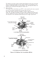
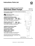
2-1/8" Bellows Unit Assembly (BUA)
Drive Arm
Hole Plug
(DO NOT LOOSEN)
Spring Post
Torque Tube Gland Nut
(DO NOT LOOSEN)
Range Spring
Assembly
Retainer Nut
Torque
Tube
Shaft
Push Rod
Range
Springs Spring
End Cup
Lock
Nut
3-3/4" Bellows Unit Assembly (BUA)
Figure 2-2. Bellows Unit Assemblies (BUAs)
6
D. Torque Tube Assembly
Needle Beaing
Center Plate
O-Ring Seal
Weld
Torque Tube
Lock Nut
Torque Tube
Torque Tube
Shaft
8°
Drive Arm
Valve Stem
Disc
Rotation
0.200"
Bellows Travel
Weld
Ball Bearing
Minature
Precision
Ball Bearing
Valve Stem
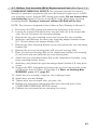
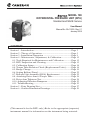
Figure 2-3. Torque Tube Assembly
E.
As illustrated in Figure 2-3, the torque tube assembly consists of a torque
tube, a torque tube shaft, and the supporting members. The outboard end
of the torque tube shaft is attached to the center plate. The torque tube
shaft, located in the center of the torque tube, is welded to the inboard end
of the tube.
Movement of the bellows is transmitted by the drive arm to the torque tube
as a rotary motion. Since the torque tube is attached to the center plate,
the tube must twist when subjected to torque. The torque tube shaft, which
is freely supported within the torque tube at its outer end, but connected
to the torque tube and drive arm at its inner end, rotates through the same
angle as the differential pressure unit.
NOTE: An extended torque tube is used on electronic transmitters and
explosion-proof instruments.
Pulsation Dampener
The pulsation dampener (see Figure 2-1) controls the flow of fill-liquid
between the high and low-pressure bellows with an externally adjustable
pulsation dampener needle valve. Restriction of liquid flow reduces the
effects of pulsation. In applications where pulsation is not a problem, the
needle valve is set to the fullopen position.
7
(Blank Page)
8
SECTION 3 - INSTALLATION/OPERATION
3-1. Unpacking
The 199 DPU should be inspected at time of unpacking to detect any damage
that may have occurred during shipment.
NOTICE: The instrument was checked for accuracy at the factory — do not
change any of the settings during examination or accuracy will be affected.
NOTICE: For application in critical media, requiring special cleaning processes and precautions, a polyethylene bag is used to protect the instrument
from contamination. This protective bag should be removed only under
conditions of controlled extreme cleanliness.
NOTICE: Do not locate the instrument near vents or bleed holes that discharge corrosive vapors or gases.
3-2. Mounting
A. Flush or Panel Mounting
Attach the case of the instrument (recorder, indicator etc.) to the panel.
Refer to the Installation and Operation Manual for the specific instrument
for the mounting details.
B. Pipe Mounting
Refer to the Outline Dimension Drawing in Section 6 for the pipe mounting diagram. The DPU must be mounted approximately level to operate
properly.
3-3. Piping — Standard Practices
A. All Applications (flow and liquid level)
1 . Shorten the distance between the primary device and the DPU as
much as possible. Distances exceeding 100 feet are not recommended.
For distances up to 50 feet, use 1/4-inch or 3/8-inch pipe or tubing.
For runs of 50 to 100 feet, use 1/2-inch pipe or tubing. The recommended limitation does not apply if an air purge or blow-back system is
used.
2. Slope all piping at least one inch per linear foot to avoid liquid or gas
entrapment.
3. Provide two feet of uninsulated piping between the DPU and the primary device for each 100°F (+37.8°C) in excess of +200°F (+93.3°C).
4. Assure that the temperature of the DPU never exceeds 180°F
(+82°C). When steam tracing is necessary, the steam pressure should
not exceed five pounds per square inch and insulation should not be
used. If pressure must exceed five pounds per square inch, limit the
length of tubing around the DPU to two turns and do not insulate.
5. Install a suitable pulsation dampening device upstream of the DPU.
Where severe pulsation is present, the accuracy of the flow measurement will be affected.
6. Mount the DPU on a solid support to minimize vibration. Tighten all
points, using a suitable compound; leaks in piping can cause measurement errors.
9
3-3. Piping — Standard Practices (Cont.)
7. Rotate the housing as necessary to place the connection in the proper
position. The DPU has connections in the pressure housings to accommodate various pipe sizes (refer to Section 6- Drawings).
8. Install a valve manifold connecting the DPU and the source of differential pressure to facilitate operation and checking of the DPU.
9. Locate all shutoff valves and bypass valves to be readily accessible from
the front of the instrument. Locate block valves at the source of differential pressure.
B. Flow Applications
Assure that the DPU high-pressure housing is connected to the upstream
tap of the primary device.
NOTE: To prevent overheating the DPU during blowdown, the operator
should monitor the temperature by placing his hands on the pipe between
the DPU and the manifold pipe containing the vent valves.
C. Liquid Level Applications
The process media may be used as a reference leg seal fluid when it is of a
type that will condense in the reference leg under all conditions.
If the process or process media characteristics are such that the above conditions cannot be met, a special reference leg seal fluid will be required. The
special seal fluid media characteristics are such that the above conditions
cannot be met, a special reference leg seal fluid will be required. The special
seal fluid must not be volatile and must not be miscible with the process
media. Also, the difference in the densities of the special seal fluid and the
process media will require compensation in calculating the differential pressure range of the DPU.
WARNING
EXPLOSION HAZARD. ORGANIC COMPOUNDS, OIL, GREASE,
DIRT, OR SCALE OF ANY KIND CANNOT BE TOLERATED IN AN
OXYGEN INSTALLATION.
3-4. General Startup Practice Considerations
Observe the following practices when starting up an instrument.
1. Always start with the block valves closed.
2. Perform a zero check on the instrument as follows.
NOTICE: For gas service, it is recommended that zero check be performed
with both block valves closed. If the gas flow is pulsating, there may be a
standing wave effect in the process line which can displace the indicator
and appear as a zero error.
a. Open the bypass valve(s), then open one shutoff valve. This procedure equalizes the pressure between both sides of the instrument. The
instrument should indicate zero.
b. If the instrument does not indicate zero, check for gas or liquid entrapment in the lines or in the DPU (depending on the orientation of the
piping layout and service).
10
3-4. General Startup Practice Considerations (Cont.)
2. Perform a zero check on the instrument as follows (Cont.)
c. If necessary, adjust the pen or pointer by turning the zero adjust on the
instrument.
3. Check the manifold and piping for leaks as follows.
a. Open the bypass valve(s), then open one shutoff valve to pressurize the
instrument.
b. Close the shutoff valve and the bypass valve.
c. Any leakage will be indicated by pen or pointer movement, up or down
scale.
NOTE: Be careful not to subject the DPU to unnecessary shock or overrange pressure during operations.
11
(Blank Page)
12
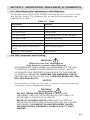
SECTION 4 - MAINTENANCE, ADJUSTMENT, & CALIBRATION
4-1. Tools Required for Maintenance and Calibration
A calibration tool kit (P/N 0202-1005B) containing the necessary tools is available from the factory. The following tools are required for maintenance and
calibration of the DPU:
Table 4-1. Tools
Description
Purpose
Screwdriver
Bracket screws
7/16" Hex wrench
Housing bolts
5/8" Hex wrench
Housing bolts
3/4" Hex wrench
Housing bolt/stud nut (6,000 PSI units)
1/8" Allen wrench
Dampener Adjustment
1/2" Open end wrench
Pushrod - bellows cup connection
1/2" 12-point socket
Housing bolt (6,000 PSI units)
Modified Box/Open-ended Wrench
(7/16")
Kickoff spring lock nut
100 ft.-lb. Torque wrench
Housing bolts
4-2. DPU Inspection and Cleaning
WARNING
(High-pressure Gas Installations
with pressures greater than 200 psig)
HIGH-PRESSURE GAS HAZARD ON DISASSEMBLY OF THE DPU.
TO PREVENT POSSIBLE SEVERE PERSONAL INJURY, DEATH,
OR SUBSTANTIAL PROPERTY DAMAGE DUE TO THE RELEASE
OF INTERNAL PRESSURE, PERFORM THE PRESSURE CHECK
PROCEDURE THAT FOLLOWS (Step A) BEFORE REMOVING THE
DPU HOUSING BOLTS.
NOTICE
If accumulation of solids or semi-solids is extensive, remove the housings
carefully to prevent damaging the bellows.
WARNING
(Housing Bolts)
DO NOT REUSE HOUSING BOLTS. IF BOLTS ARE
DISTURBED, REPLACE WITH NEW BOLTS, PER TABLE 4-2
(STANDARD) or TABLES 4-3/4-4 (NACE).
REUSE OF HOUSING BOLTS, ESPECIALLY IN CRITICAL
APPLICATIONS LIKE HYDROGEN SULFIDE AND SALT WATER
EXPOSURES, CAN RESULT IN SEVERE INJURY, DEATH
OR SUBSTANTIAL PROPERTY DAMAGE DUE TO BOLT
FAILURE.
13
Ti
ght
ent
hebol
t
sandr
et
ur
nt
heuni
tt
ot
hef
ac
t
or
yf
orr
epai
r
.
1000
Part No.
Rotation
(Note 3)
SWP
Torque Lb/Ft
(Note 2)
Housing
Lube (Note 1)
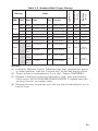
Table 4-2. Standard Bolt Torque Ratings
6
0199-1345C
Yes
45
180°
12
0199-1345C
Yes
40
270°
Bolts
Mat'l
Mat'l
Size
Steel
Steel
3/8-16 x 4.5
Cres
Steel
3/8-16 x 4.5
Qty
Alum
Steel
3/8-16 x 4.5
6
0199-1345C
Yes
40
180°
2500
Steel
Steel
1/2-13 x 5.5
6
0199-0085C
Yes
95
180°
3000
Cres
Steel
1/2-13 x 5.5
12
0199-0085C
Yes
80
180°
4500
Steel
Steel
1/2-13 x 5.5
12
0199-0085C
Yes
95
180°
Steel
(Stud)
1/2-20 x 7
12
0199-1001C
Steel
(Nut)
1/2-20
24
0199-1002C
Yes
105
180°
(Note 4)
Steel
(Bolt)
1/2-20 x 6
12
0199-1346C
Steel
(Nut)
1/2-20
12
0199-1002C
Yes
105
180°
(Note 4)
6000
6000
NOTES:
(1) Lubricants: Molykote G paste, Teflon-base pipe dope, graphite-base grease,
or similar lubricants. Lube first 2 threads only. Do not lube bearing surface.
(2) Torque on bolts is accomplished in 3 or 4 steps. Tighten UNIFORMLY.
(3) Rotation of bolt head is measured after bolt is "snug," with approximately
5 lb/ft torque. DO NOT EXCEED THIS ROTATION. To tighten bolts without torque wrench, use rotation values.
(4) Rotation reference for bolt with nut is the sum total of bolt head plus nut, or
total of 2 nuts.
15
Table 4-3. NACE Bolt Torque Ratings
SWP
Item
Fastener
Bolt Size
2000 PSI
(13.8 MPa)
3000 PSI
(20.7 MPa)
4500 PSI
(31.0 MPa)
12 Pt. Head Bolt
12 Pt. Head Bolt
with Hex Nut
12 Pt. Head Bolt
with Hex Nut
1/2-13 x 5.5"
1/2-20 x 6"
1/2-20 x 6"
B7M/L7M Steel
B7M/L7M Steel
B7M/L7M Steel
Nut Size
N/A
1/2-20
1/2-20
Nut Material
N/A
4140 Steel
4140 Steel
6
12
12
Bolt Part Number
0220-1075J
S408-0064Z
S408-0064Z
Nut Part Number
N/A
S408-0021Z
S408-0021Z
HSG. Gasket
0001-1140R
S528-0001Z
S528-0001Z
HSG. O-RIng
0001-1099R
N/A
N/A
55-60
55-60
55-60
Bolt Material
Quantity
Torque (ft/lbs)
SPECIAL NOTES:
(1) Lubricants: Molykote G paste, Teflon-base pipe dope, graphite-base grease,
or similar lubricants. Lube first 2 threads only. Do not lube bearing surface.
(2) Torque on bolts is accomplished in 3 or 4 steps. Tighten UNIFORMLY.
(3) If originally supplied with unit, re-install the "Do Not Reuse Bolts" and
"NACE" product tags.
16
Table 4-4. Special 6,000 PSI NACE Bolt Torque Ratings
(6,000 PSI NACE Units/Bolts available from Canada Only)
SPECIAL NOTES:
(1) Lubricants: Molykote G paste, Teflon-base pipe dope, graphite-base grease, or
similar lubricants. Lube first 2 threads only. Do not lube bearing surface.
(2) Torque on bolts is accomplished in 3 or 4 steps. Tighten UNIFORMLY.
(3) For DP units marked as 1850 PSI (12.7 MPa) and 1500 PSI (10.3 MPa)
originally supplied with 12- point head bolts, Cameron has re-rated these lower
pressure DPUs to 2000 PSI (13.7 MPa). Apply the parts and use the torque
values for the 2000 PSI model (Table 4-3).
(4) For DP units marked as 1500 PSI (10.3 MPa) originally supplied with 6-point
head bolts, use a standard B7 alloy steel bolt that is suitable only for
applications where the application environment is not deemed to be sour.
WIth the exception of 0199-0085C bolts, apply the parts and use the torque
values for the 2000 PSI model (Table 4-3).
(5) If originally supplied with unit, re-install the "Do Not Reuse Bolts" and "NACE"
product tags.
All
199 DPU
DPUas
asactuator
actuatorare
are
calibrated
at the
factory.
All NuFlo
Bartoninstruments
instruments using
using 199
calibrated
at the
factory.
All DPUs
DPUs sold
sold as
as replacement
forfor
other
applications
are are
All
replacementunits
unitsororasasactuators
actuators
other
applications
checked for
checked
for accuracy
accuracyprior
priortotoshipment.
shipment.
4-5. Range Change
Changing the range of the Model 199 DPU requires replacing the bellows unit
assembly with a unit of the desired range (see para. 4-7 Bellows Unit Assembly
(BUA) Replacement).
WARNING
(High-pressure Gas Installations
with pressures greater than 200 psig)
HIGH-PRESSURE GAS HAZARD ON DISASSEMBLY OF THE DPU.
TO PREVENT POSSIBLE SEVERE PERSONAL INJURY, DEATH,
OR SUBSTANTIAL PROPERTY DAMAGE DUE TO THE RELEASE
OF INTERNAL PRESSURE, PERFORM THE PRESSURE CHECK
PROCEDURE IN PARA. 4-2, Step A BEFORE REMOVING THE
DPU HOUSING BOLTS.
NOTICE
If accumulation of solids or semi-solids is extensive, remove the housings
carefully to prevent damaging the bellows.
WARNING
(Housing Bolts)
DO NOT REUSE HOUSING BOLTS. IF BOLTS ARE
DISTURBED, REPLACE WITH NEW BOLTS, PER TABLE 4-2
(STANDARD) or TABLES 4-3/4-4 (NACE).
REUSE OF HOUSING BOLTS, ESPECIALLY IN CRITICAL
APPLICATIONS LIKE HYDROGEN SULFIDE AND SALT WATER
EXPOSURES, CAN RESULT IN SEVERE INJURY, DEATH
OR SUBSTANTIAL PROPERTY DAMAGE DUE TO BOLT
FAILURE.
NOTICE: The calibration range of the DPU was carefully set at the factory. The
following procedure maintains the original factory bellows travel setting while
the range spring change is performed. This procedure must be strictly followed
while changing the range spring assembly or altering the adjustment.
To replace the range spring assembly with either a new assembly of the same
range or one with a different range value, proceed as follows (this procedure assumes that the DPU is either connected to an indicating instrument or fitted with
a scale and pointer to measure torque tube shaft movement):
A. 2-1/8-inch Dia. Bellows
1. Remove the D PU from service.
2. Remove the pressure housing bolts and the low-pressure housing.
3. With the pointer at zero, remove the spring retainer screw, retainer
springs, and the range spring assembly.
NOTE: The pointer will shift from zero. This is a normal action and the
pointer should not be readjusted at this point.
4. Install the new range spring assembly onto the push rod, and replace
the spring retainer screw.
(Continued on next page)
19
A. 2-1/8-inch Dia. Bellows (Cont.)
5. If the pointer is set above zero, rotate the spring adjustment clockwise
until the pointer is set at zero. If the pointer is below zero rotate the
spring adjustment conterclockwise until the pointer is set at zero.
6. Replace and tighten the lock nut. If the pointer shifts from zero, loosen
the lock nut and reset the pointer as in step 5. Tighten the lock nut.
7. Replace the low-pressure housing and install NEW bolts (new gaskets
are recommended). Use the torque values listed in Tables 4-2 through
4-4. Refer to Housing Bolt WARNING, para. 4-5, page 19.
8. Calibrate in accordance with the manual for the actuated instrument.
B. 3-3/4-inch Dia. Bellows Without Kickoff Spring (>50" w.c.)
1. Remove the instrument from service.
2. Remove the pressure housing bolts and the low-pressure housing.
3. With the pointer set at zero, remove the lock nut retainer nuts, and the
range spring assembly. To remove the range spring assembly, rotate
the assembly counterclockwise while pulling outward on the assembly.
NOTE: The pointer will shift from zero. This is a normal action and the
pointer should not be readjusted at this point.
4. Thread the new assembly onto the push rod, and align the holes in the
range spring assembly with the spring posts. Replace and tighten the
retainer nuts.
5. Using a spanner wrench, rotate the spring adjustment until the pointer
is set at exact zero. Replace and tighten the lock nut. The pointer must
remain at thezerosetting. If the pointer shifts from zero, loosen the lock
nut and repeat this step.
6. Replace the low-pressure housing and bolts (new gaskets are recommended). Use the toque values listed in Tables 4-2 through 4-4. Refer
to Housing Bolt WARNING, para. 4-5, page 19.
7. Calibrate in accordance with the manual for the actuated instrument.
C. 3-3/4-inch Dia. Bellows w/Kickoff* Spring (see Figure 4-2)
NOTE: The kickoff spring is supplied with the 0-40" w.c. and lower range DPUs
as standard equipment. It is optional with 0-50" w.c. DPUs.
*Also referred to as the "anti-stick" spring.
1 Remove the instrument from service. Set the pointer (or pen) at zero, using
the instrument zero adjustment.
2. Remove the pressure housing bolts and remove the low-pressure housing.
3. With the pointer set at zero, remove the lock nut, four spring retainer nuts,
washer and lock nut, and range spring assembly.
NOTE: The pointer will shift from zero. This is a normal action and the
pointer should not be readjusted at this time.
4. Install the range spring assembly, using a 1/2-inch open-ended wrench to
connect the push rod to the low-pressure bellows cup.
NOTE: The range spring assembly consists of the range springs, kickoff
spring assembly, and the push rod. The assembly is furnished as a complete
and assembled unit.
20
C.
5.
6.
7.
8.
3-3/4-inch Dia. Bellows w/Kickoff* Spring (Cont.) (see Figure 4-2)
Position range spring assembly over retainer posts and replace retainer nuts.
Insert the tubing between the range springs and tighten inboard lock nut.
Zero the pointer by adjusting the spud on the push rod. Be sure that the
kickoff spring is not engaged during this operation.
Position the kickoff spring to prevent interference with the coil springs and
tighten the kickoff spring lock nut. If clearance is needed for the wrench
during this operation, note the position of the spud (measure with a scale
or count threads to the end of the push rod) and move the spud for the
required clearance. After the lock nut is tightened, return the spud to the
original position.
Figure 4-2. Kickoff Spring Assembly
NOTE: The lock nut requires a modified 7/16", 12-point box wrench for tightening (Figure 4-3).
Figure 4-3. Wrench Modification
9.
Check the back-clearance between the kickoff spring and the slot. Use a
wire feeler gage or comparable measuring device. The clearance will vary
between each individual slot but must be at least 0.005-inch for any one
slot to prevent interference with instrument zero. Add or remove washers
as required to obtain the proper clearance. Tighten the lock nut securely.
10. Install the jam nut and lock the spud to the push rod. Hold with pliers. If the
spud was moved in step 9, return the spud to the proper position before
tightening the jam nut.
21
C. 3-3/4-inch Dia. Bellows w/Kickoff* Spring (Cont.)
11. Apply 100 percent negative pressure to the high-pressure side of the DPU
and repeat the clearance check and adjustment of step 9.
12. Apply 100 percent positive pressure to the high-pressure side of the DPU
and repeat the clearance check and adjustment of step 9.
13. Release all pressure from the instrument and replace the low-pressure housing. Use new gaskets.
14. Replace the housing bolts. Use the torque values listed in Tables 4-2
through 4-4. Refer to Housing Bolt WARNING, para. 4-2, page 13.
4-6. Setting Bellows Travel
The travel of the DPU bellows must be adjusted if one of the following occurs.
1. The range spring assembly is removed without following the procedure.
2. Broken range springs are replaced.
3. The indicator pointer has excessive overtravel.
4. The indicator pointer has excessive undertravel.
To set the bellows travel requires that the DPU be attached to the actuated
instrument and connected to a test pressure source. The procedure for this
adjustment is presented in the manual of the actuated instrument.
4-7. Bellows Unit Assembly (BUA) Replacement (See Figure 2-1)
WARNING
(High-pressure Gas Installations
with pressures greater than 200 psig)
HIGH-PRESSURE GAS HAZARD ON DISASSEMBLY OF THE DPU.
TO PREVENT POSSIBLE SEVERE PERSONAL INJURY, DEATH,
OR SUBSTANTIAL PROPERTY DAMAGE DUE TO THE RELEASE
OF INTERNAL PRESSURE, PERFORM THE PRESSURE CHECK
PROCEDURE IN PARA. 4-2, Step A BEFORE REMOVING THE
DPU HOUSING BOLTS.
NOTICE
If accumulation of solids or semi-solids is extensive, remove the housings
carefully to prevent damaging the bellows.
WARNING
(Housing Bolts)
DO NOT REUSE HOUSING BOLTS. IF BOLTS ARE
DISTURBED, REPLACE WITH NEW BOLTS, PER TABLE 4-2
(STANDARD) or TABLES 4-3/4-4 (NACE).
REUSE OF HOUSING BOLTS, ESPECIALLY IN CRITICAL
APPLICATIONS LIKE HYDROGEN SULFIDE AND SALT WATER
EXPOSURES, CAN RESULT IN SEVERE INJURY, DEATH
OR SUBSTANTIAL PROPERTY DAMAGE DUE TO BOLT
FAILURE.
22
4-7. Bellows Unit Assembly (BUA) Replacement (Cont.) (See Figure 2-1)
COMPONENT REMOVAL NOTICE: See (separate) actuated instrument
Manual for particular components that must be removed to gain access to DPU
case mounting screws. Support DPU during disassembly. Do not loosen drive
arm hold plug (located in the top of the BUA center plate) when removing
mounting bracket. If plug is loosened, bellows fill fluid will be lost.
NOTE: The reference designations listed relate to Parts Drawing in Section 5.
1.
2.
3.
4.
5.
6.
7.
8.
9.
10.
11.
12.
13.
14.
15.
Disconnect the DPU piping and remove the instrument from service.
Loosen the actuated instrument drive arm and slide off of the torque tube
shaft. Do not disconnect the instrument linkage.
Remove the four case-retaining screws and remove the case assembly.
(Indicators only) Remove the three pipe mounting adapter bracket screws
(10, 11) and remove the adapter bracket (13).
Remove the three mounting bracket screws and remove the case mounting
bracket (18).
Remove the pressure housings bolts and pressure housings (26).
Place the pressure housings (26) on the replacement bellows unit assembly
(1) and insert and start (only) the pressure housing bolts.
Attach the case mounting bracket (18) to the replacement assembly, using
three mounting bracket screws.
(Indicators only) Attach the pipe mounting adapter bracket (13) using three
screws.
Support the DPU and tighten and torque the pressure housing bolts to the
specifications listed in Tables 4-2 through 4-4. Refer to Housing Bolt
WARNING, para. 4-7, page 22.
Attach the case assembly using four case retaining screws.
Attach drive arm and linkage.
Tighten drive arm to torque tube, per para. 4-8.
Replace any instrument components that were removed (refer to the
COMPONENT REMOVAL NOTICE above).
Calibrate the instrument before returning it to service.
23
4-8. Attaching Drive Arm to Torque Tube
Figure 4-4. Drive Arm to Torque Tube Connection
1.
Slip drive arm over torque tube shaft; clear end of torque tube housing by
approximately 0.030 inches before securing to prevent interference.
2. To tighten the drive arm assembly onto the torque tube shaft:
a. Supporting block and shaft, tighten clamp screw until snug to shaft.
b. Still supporting block/shaft, tighten clamp screw an additional:
• Sintered: 1/3 to 1/2 turn (screw can normally turn one full revolution before breaking.)
• Slotted: 1/4 to 1/3 turn (slot in the slotted clamp block should still
be open.)
NOTICE: For Nuclear, Seismic, and High Shock Qualified Units, perform Drive
Arm Tightness Test, per para. 4-9.
4-9. Drive Arm Tightness Test
(Nuclear, Seismic, and High Shock Qualified Units Only)
This procedure tests the drive arm to torque tube attachment for tightness, by
applying torque developed by the DPU onto a fixed drive arm. Care should be
taken to apply pressure slowly, as torque is being applied to the connection
through the torque tube drive shaft and not the torque tube itself.
With pointer at normal 0% torque tube rotation position (max. minimum scale
position or 0% on a normal 0 to 100% scale unit), adjust drive arm stop bracket
(or use alternate means) to prevent pointer from moving (stop bracket interferres
with drive arm movement). Note: On reverse acting/split range units, it will be
necessary to pressurize DPU to move pointer to max. minimum scale position,
and on suppressed units, it will be necessary to apply pressure to establish a
reference point to check for "zero" shift.
Pressurize DPU as required to full calibrated scale differential pressure (100% of
the full scale range). This achieves 8-degrees of torque tube drive shaft equivalent torque onto the connection.
Observe shift in the unit "zero" following DPU depressurization (as required) and
drive arm stop bracket readjusting (to allow free movement of drive arm and
pointer). A downscale (counter-clockwise) shift in "zero" of greater than 1/2% is
indicative of drive arm slippage necessitating further clamp block tightening.
24
4-10. Adjusting Pulsation Dampener (See Figure 2-1)
1. Remove dust cover and insert 1/8 hex key into needle valve.
2. Turn valve clockwise to closed position, approx. 3 turns.
3. Back out valve 1/2 turn or as required to reduce pulsations/shock pressures.
4-11. Troubleshooting
See Table 4-5 and refer to actuated instrument Manual for more information.
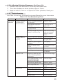
Table 4-5. Troubleshooting Chart
Trouble*
Possible Source
Probable Cause
Corrective Action
Low or No
Indication
Primary Element
or Differential
Pressure Source
Orifice installed backwards
or oversized
Replace orifice
Flow blocked upstream
from run
Clean out run or
open valve
Loss of liquid in reference
leg (liquid level)
Refill reference leg
Density changes in process
media or reference leg
Refill reference leg
with same density
liquid as process
media
Pressure tap holes plugged
Clean out piping
Bypass valve open or
leaking
Close bypass valve(s)
or repair leaks
Liquids or gases trapped
in piping
Vent piping
Block or shutoff valves
closed
Open block or shutoff valves
Piping leaks, HP side
Repair leaks
High flapper setting
Align drive arm
re-calibrate
Housing(s) filled up with
solids, restricting bellows
movement
Clean out housing(s)
Gas trapped (liquid service)
or liquid trapped (gas
service) in housing(s)
Vent housing(s)
HP Housing gasket leaks
Replace gasket
DPU tampered with
Return BUA for
repair
Loose links/movements
Tighten or replace
Out of calibration
Calibrate
Corrosion or dirt in mechanism
Clean or replace
Pointer loose
Tighten pointer
Piping from
Primary Element
to DPU
Bellows Unit
Mechanism
25
Table 4-5. Troubleshooting Chart (Continued)
High
Indication
Primary
Orifice partially restricted
or too small
Clean out or replace
Piping from
Primary Element
to DPU
Leak in LP side piping
Repair leaks
Bellows Unit
Gas trapped (liquid service)
in LP housing or liquid
trapped (gas service) in HP
housing
Vent housing
LP housing gasket leaks
Replace gasket
Range spring broken or
DPU tampered with
Return BUA for
repair
Loose links or movements
Repair or replace
Out of calibration
Calibrate
Primary
Flow pulsating
Install dampening
device upstream of
DPU run
Piping from
Primary Element
to DPU
Liquid trapped in gas
piping or gas bubble in
liquid piping
Remove (see Startup
Procedure-Section 3)
Mechanism
Erratic
Indication
Vapor generator incorrectly Repipe
installed
Bellows Unit
Mechanism
26
Reference leg gassy or
liquid vaporizing
See piping instructions
Obstructed bellows travel
Clean bellows
Gas trapped in DPU HP or
LP housing
Remove (see Startup
Procedure-Section 3)
Linkage dragging or dirty
Adjust or clean
Pointer dragging on scale
plate
Adjust
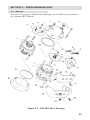
SECTION 5 - PARTS DRAWING/LIST
5-1. General
The parts list and parts identification drawing(s) for the DPU are presented in
the separate DPU Manual.
Figure 5-1. 199 DPU Parts Drawing
27
WARNING
(NACE SERVICE)
HAZARDOUS GAS AND PRESSURE HAZARD IN NACE QUALIFIED
SERVICE. USE ONLY NACE QUALIFIED REPLACEMENT PARTS
FOR HOUSINGS, BOLTS, AND BUA. FOR NACE BOLT PART
NUMBERS, REFER TO TABLES 4-3 & 4-4.
ANY DEVIATION FROM USE OF QUALIFIED NACE PARTS IN
NACE SERVICE WILL VOID THE INSTRUMENT/DPU NACE
RATING(s).
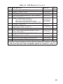
Table 5-1. 199 Parts List
ITEM DESCRIPTION
PART NO.
PER
UNIT
1
1
BELLOWS UNIT ASSEMBLY (BUA)
(SPECIFY)
*2
POST, CALIBRATION SPRING RETAINER
(FOR 3-3/4" BELLOWS)
0199-0019C
4
3
ROD, SPRING PUSH
0199-0049C
1
*4
SCREW, RETAINER, 6-32 x 5/16"
0111-0049J
8
*5
SPRING ASSEMBLY, CALIBRATION TENSION
(FOR 2-1/8" BELLOWS)
(SPECIFY)
1
6
NUT, LOCK - SPRING ADJUST
0199-0144C
1
7
PLUG, PIPE, 1/4" NPT, STEEL
0199-0191C
2
8
PLUG, PIPE, 1/2" NPT, STEEL
0199-0192C
9
BOLT, HOUSING (STANDARD UNITS):**
STAINLESS STEEL, 1000 PSI UNITS
STEEL, 2500/3000/4500 PSI UNITS
0199-1345C
0199-0085C
STUD, ALLOY STEEL, 1/2-20 X 7 FOR 6000
PSI UNITS (NOT SHOWN)
0199-1001C
BOLT FOR 6000 PSI UNITS (NOT SHOWN)
0199-1346C
2
A/R
*10
SCREW, PIPE MOUNT ADAPTER, 3/8-16 X 3/4"
0210-0012J
1
11
SCREW, SCH CAP, STEEL, 3/8-16 X 1-1/2" LG.
0220-1102J
2
*12
SCREW, 3/8-16 X 5/8", STEEL (FOR ITEM 13)
0310-0013J
3
13
ADAPTER, PIPE MOUNTING
0199-0988C
1
*14
NUT, SPRING RETAINER, HEX, 6-32,
SM PATTERN, SST (FOR 3-3/4" BELLOWS)
0500-0028J
8
*15
ASSEMBLY, RANGE SPRING
(FOR 3-3/4" BELLOWS)
(SPECIFY)
16
SPACER, INDICATOR BRACKET
0199-0006C
17
SCREW, INDICATOR BRACKET
(SOC. FLAT, 3/8-16 X7/8", ST)
0240-0003J
18
BRACKET
(SPECIFY)
19
SCREW, INDICATOR BRACKET, HEX, WASHER
HD., 3/8 X 1-1/8
0002-1009T
20
SCREW, RECORDER BRACKET, HEX, WASHER
HD., 3/8-16 X 1/2
0002-0034T
28
1
2
1
1
2
1
Table 5-1. 199 Parts List (Continued)
*21
O-RING, 2-127, NITRILE N3 **
0001-1178R
PER
UNIT
1
*22
GASKET, TORQUE TUBE
0199-0209C
1
23
NOT USED
24
SCREW, RECORDER BRACKET, HEX, WASHER
HD., 3/8-16 X 5/8
0002-0033T
*25
GASKET, PRESSURE HOUSING: **
1000 PSI ALUMINUM UNITS
2500/3000/4500 PSI STEEL UNITS
1000/3000/6000 PSI SST & MONEL UNITS
0199-0027C
0199-0027C
0199-0184C
26
HOUSING, PRESSURE
(SPECIFY)
27
WASHER, LOCK, 3/8"
(USED WITH ITEMS 10 AND 11)
0275-0049C
28
NOT USED
29
NUT, 1/2-20, 6000/3000 PSI MONEL UNITS
(USED WITH ITEM 9)
0199-1002C
*30
PLUG, DAMPENER VALVE (NOT SHOWN)
BD HD., 1/4-28 X 1/4, SST
0199-0036C
ITEM DESCRIPTION
PART NO.
2
2
2
1
A/R
1
31
NOT USED
*32
WRENCH, RANGE SPRING ADJUSTMENT
0199-0142C
1
33
KEYS, SET OF HEX (NOT SHOWN)
0016-0013T
1
NOTES: * INDICATES RECOMMENDED SPARE PART; A/R INDICATES AS
REQUIRED; WHEN ORDERING PARTS, SPECIFY INSTRUMENT SERIAL NUMBER.
** FOR NACE SPECIFIC PART NUMBERS, REFER TO TABLES 4-3 AND 4-4.
29
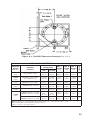
SECTION 6 - OUTLINE DIMENSION DRAWINGS
Figure 6-1. 199 DPU Dimension Drawing (Part 1 of 2)
30
Figure 6-1. 199 DPU Dimension Drawing (Part 2 of 2)
PRESSURE
RATING
PSI (MPa)
HOUSING
MATERIAL
1,000
(6.9)
PRESSURE
CONNECTION
DIM. B
INCHES
(mm)
DIM. C
INCHES
(mm)
# BOLTS
Table 6-1. 199 DPU Dimensions
TOP
BOTTOM
DIM. A
INCHES
(mm)
CAST ALUM. 356T6
1/2 NPT
(Note 1)
1/4 NPT
(Note 1)
6-5/8
(168.3)
2
(50.8)
2-9/64
(54.4)
6
NACE
2,000
(13.8)
FORGED ST. AISI C1018
(For NACE Service)
1/2 NPT
(Note 1)
1/4 NPT
(Note 1)
Ø7
(177.8)
2
(50.8)
2-9/64
(54.4)
6
2,500
(17.2)
FORGED ST. AISI C1018
1/2 NPT
(Note 1)
1/4 NPT
(Note 1)
Ø7
(177.8)
2
(50.8)
2-9/64
(54.4)
6
3,000
(20.7)
FORGED STNL. ST. 316
1/2 NPT
(Note 1)
1/4 NPT
(Note 1)
Ø7
(177.8)
2
(50.8)
2-9/64
(54.4)
12
FORGED ALLOY ST. 4142
1/2 NPT
(Note 1)
1/4 NPT
(Note 1)
Ø7
(177.8)
2
(50.8)
2-9/64
(54.4)
12
FORGED ALLOY ST. 4142
FORGED STNL. ST. 17-4 PH
9/16-18
UNF
(Note 2)
9/16-18
UNF
(Note 2)
Ø7
(177.8)
2
(50.8)
2
(50.8)
12
FORGED ALLOY ST. 4142
FORGED STNL. ST. 17-4 PH
1/2 NPT
(Note 1)
1/4 NPT
(Note 1)
Ø7
(177.8)
2
(50.8)
2-9/64
(54.4)
12
4,500
(31.0)
6,000
(41.4)
Note 1: Can be reversed when ordered or can be rotated 180° in the field.
Note 2: Suitable for use with Aminko fittings (American Inst. Co., Silver Springs, MD.) or equiv..
Note 3: All Standard pipe fittings furnished by customer.
(Metric conversions are approximate.)
31
Product Warranty
A. Warranty
Cameron International Corporation ("Cameron") warrants that at the time of shipment, the products manufactured by Cameron and sold hereunder will be free from
defects in material and workmanship, and will conform to the specifications furnished
by or approved by Cameron.
B. Warranty Adjustment
(1) If any defect within this warranty appears, Buyer shall notify Cameron immediately.
(2) Cameron agrees to repair or furnish a replacement for, but not install, any product which within one (1) year from the date of shipment by Cameron shall, upon
test and examination by Cameron, prove defective within the above warranty.
(3) No product will be accepted for return or replacement without the written
authorization of Cameron. Upon such authorization, and in accordance with
instructions by Cameron, the product will be returned shipping charges prepaid
by Buyer. Replacements made under this warranty will be shipped prepaid.
C. Exclusions from Warranty
(1) THE FOREGOING WARRANTY IS IN LIEU OF AND EXCLUDES ALL OTHER
EXPRESSED OR IMPLIED WARRANTIES OF MERCHANTABILITY, OR FITNESS
FOR
A PARTICULAR PURPOSE, OR OTHERWISE.
(2) Components manufactured by any supplier other than Cameron shall bear only
the warranty made by the manufacturer of that product, and Cameron assumes no
responsibility for the performance or reliability of the unit as a whole.
(3) "In no event shall Cameron be liable for indirect, incidental, or consequential damages nor shall the liability of Cameron arising in connection with any products sold
hereunder (whether such liability arises from a claim based on contract, warranty, tort,
or otherwise) exceed the actual amount paid by Buyer to Cameron for the products
delivered hereunder."
(4) The warranty does not extend to any product manufactured by Cameron which has
been subjected to misuse, neglect, accident, improper installation or to use in violation
of instructions furnished by Cameron.
(5) The warranty does not extend to or apply to any unit which has been repaired or
altered at any place other than at Cameron's factory or service locations by persons
not expressly approved by Cameron.
Product Brand
Barton® is a registered trademark of Cameron International Corporation
("Cameron").
MEASUREMENT SYSTEMS
Formerly: NuFlo Measurement Systems • Barton Instrument Systems • Caldon, Inc.
HOUSTON
HEAD OFFICE
ASIA
PACIFIC
281.582.9500
+603.2287.1039
[email protected]
NORTH
AMERICA
EUROPE,
MIDDLE EAST
& AFRICA
1.800.654.3760
[email protected]
+44.1243.826741
[email protected]
USA • CANADA • UK • SCOTLAND • CHINA • UAE
A L G E R I A • M A L A Y S I A • S I N G A P O R E • www.c-a-m.com/flo