1
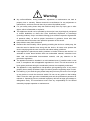
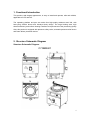
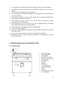
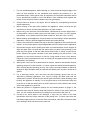
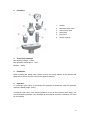
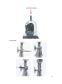
C7GBM601 C9GBM151 Gas Boiling Pan Luxury Gas Range Series User’s Manual Dear Client & User, Firstly, thanks for purchasing and using our product. All the information and guidelines of this user’s manual comply with certain applicable regulations, which come out from our long-term accumulated knowledge and experience as well as current project development situations. Limited to some special structures, additional specified items or new technology changes, the actual usage situation might be some different from what stated in this user’s manual. Should you have any question, please do not hesitate to contact the manufacturer via the method shown in back cover page of this manual. For safety purpose and efficient operation, please make this document available to users for reference. Do have them to read this manual carefully before carry out any action on this device, especially when starting. The manufacturer declines any responsibility in the event users do not follow the instructions or guidelines stated here. The user’s manual should be placed close to the device, in convenience of users’ reading before operation. We have the full authority to reserve the further technical changes of the device, in the scope of further performance improvement characteristic development. Warning Any self-modification, wrong installation, adjustment or maintenance can lead to property loss or casualty. Please contact the manufacturer for any adjustment or maintenance, and have the work done by a trained & qualified person. For your safety sake, please keep the machine away from any liquid, gas or other object, which is flammable or explosive. This appliance should not be operated by those who have physiological, perceptual or mental disabilities or those who have insufficient experience or knowledge (including children). Only in conditions of being given sufficient supervise & guarantee of personal safety, as well as proper instructions & guidance, those who were mentioned above can make some particular operation of this device. Keep children away from the device. Preserve this manual safely. When passing on/selling the device to a third party, the manuals must be handed over along with the device. All users must operate the device complying with the user’s manual and related safety guidelines. If this appliance is placed near walls, partitions or kitchen furniture and the like, it is advisable to make these facilities with non-combustible material, otherwise cover them with non-combustible heat-resistant material, and pay attention to fire prevention regulations. The appliance should be installed in a well-ventilated area, if possible under a vent hood, in compliance with all applicable regulations in force. This will ensure that all burnt gases produced during the combustion process are completely exhausted. The appliance is only applicable to low-pressure gas regulating valve. It may cause property loss or safety accidents if high or medium pressure regulating valve is used. Fire warning: If you smell the gas, please keep away from any fire source. Do not light up any device or touch the electronic switch. Do not use any phone in the building either. Close the main gas valve immediately and call the professional personnel to maintain it. Operate by force or maintain improperly will lead to large gas leakage or deflagration easily. The manufacturer won’t bear any responsibility for fire hazard caused by improper operation or maintenance. Contents 1. Functional Introduction...................................................1 2. Structure Schematic Diagram...............................................1 3. Basic Features & Parameters........................................3 4. Precautions & Recommendations..................................3 5. Working Instructions & Operation Flow..........................5 6. Routine Inspection.........................................................13 7. Cleaning & Maintenance................................................14 8. Failure Analysis & Trouble Shooting..............................14 1. Functional Introduction This product, with elegant appearance, is easy to install and operate, safe and reliable, applicable to LPG and NG. The operating platform and pan are made from high-quality stainless steel 304, with heavy-duty tubular burner and interlayer body design. The large heating area, high thermal efficiency and uniform heating contribute to improvement of the processing quality. Also, this product is equipped with pressure safety valve, automatic pressure relief device and flame failure protection device. 2. Structure Schematic Diagram Structure Schematic Diagram: C7GBM601 1 C9GBM151 2.1 Structural& Functional Features: 1. High-quality stainless steel body, equipped with water injection function. 2. High-quality and heavy-duty tubular burners with good heating efficiency. 3. Provided with functions of pressure indication, manual pressure relief, pressure relief of safety valve and over-temperature protection. 4. Food safety certificated, large-diameter drain valve, fast draining off. 5. Equipped with pulse ignition device, flame failure protection function and pilot flame standby function, safe and practical. 2 3. Basic Features & Parameters Model C9GBM151 C7GBM601 Dimension(mm) 800×900×850+60 700×700×850+60 LPG 25 16 NG 25 16 Capacity(L) 150 60 Gas Type LPG, NG,TG LPG, NG,TG Power (kW) Pressure(Pa) TG:1000 Net Weight(kg) LPG:2800 TG:1000 LPG:2800 NG:2000 NG:2000 140 112 4. Precautions & Recommendations 4.1 Transportation and Storage During transportation, the machine should be carefully handled and do not put it upside down to prevent from damaging to the shell and inside. The packaged machine should be stored in a ventilated warehouse without corrosive gas. If it needs to be stored in open air temporarily, measurement against raining is needed. 4.2 Notice for Installment Gas Connection: 1. Before installation, a quick acting disconnecting valve should be installed upstream the appliance where is easy to reach for convenience of maintenance and prompt gas cutoff in an accident. 2. Pipeline connected to the appliance should be connected with proper metal pipe. 3. After connecting the appliance to the gas system, check for leaks at joints and pipe fittings; to do so, use soapy water or a specific leak detector (spray). “No Flaming!” Water Connection: The water inlet connector is located at left front of the furnace bottom, connect it to the tap water pipe with DN 15 connector. 3 Note: 1. Installation should be done by professional technician. 2. Take out the attached battery, turn the pulse button counterclockwise, then put in the battery in the correct direction as shown and tighten the pulse button. 3. Appliance connection should conform to provisions in gas safety, installation and 4. operation. The appliance should be installed separately or assembled with other devices in accordance with provisions. The appliance is not suitable for built-in installation. 5. The appliance should be installed in a well-ventilated area, if possible under a vent hood, in compliance with all applicable regulations in force. This will ensure that all burnt gases produced during the combustion process are completely exhausted. 6. The appliance should keep a minimum clearance of 10cm away from non-combustible substance (e.g. walls, windows etc.) on both sides, and 20cm at its back. Do not install the appliance on flammable floor or materials. 7. 8. The furnace body is equipped with adjustable feet with an adjustable range ≤15mm. Making sure that the appliance is level and stable. During installation, please consider the weight of the appliance. It is advisable to install on the floor. 9. After installation, keep the appliance stable and level. Do not tilt or sway during operation. 10. Do not use gas that not applicable to the appliance as fuel, neither does high-pressure or medium-pressure regulating valve. (This appliance is only applicable to low-pressure regulating valve.) 11. Before installation, make sure that the available gas is the same as that marked on the nameplate. If not, substitute the nozzle with a suitable one. 12. If the pressure of the gas pipeline is 10% higher or lower than the rated pressure the appliance required, a regulator should be installed to ensure it reaches the rated value. 4.3 Special Note 1. 2. 3. 4. Installation, initial use and maintenance should be done by professional or licensed personnel or franchised person approved by manufacturer. This product is a commercial machine, not applicable for household use. Please keep the integrity of the appliance and remove the outer packaging. If you do have any questions, call the specialist and stop using the appliance. To avoid danger, keep the packing materials away from children. (For the materials are plastic bags, nails etc.) For initial use, the duration of ignition may be a little longer due to the air existing in the new pipeline. If it cannot be lit up for the first time, turn the ignition switch off and turn it on 3 minutes later to prevent from deflagration. Do not use gas that not applicable to the appliance as fuel, neither does high-pressure or medium-pressure regulating valve. Making sure the applicable gas is the same as the supplied one, if not, stop using. 4 5. To avoid hazard, turn the appliance off if not going to used it or if it is unattended. 6. This product is only for commercial use, not suitable for other uses, or it may cause danger. 7. Do not sway or tilt the appliance during operation. 8. Do not dismantle or self-modify the appliance. Dismantlement and self-modification 9. may cause casualty. Do not pat the product or put any heavy objects onto it. Abnormal operation may cause appliance damage and danger. 10. Do not place any objects in the vent of the gas heater. Obstruction of smoke exhaustion may do harm to health. 11. High temperature may cause scald. Do not touch the appliance directly with hands due to high temperature during or after operation. 12. Do not destroy the control panel with hard or sharp objects. 13. Do not dry heat the appliance. 14. Do not aim at the appliance with water jet during cleaning. Neither does immerse it into water to clean. 15. Turn the gas switch off before carrying out any maintenance operation. 16. Maintenance should be done by qualified technicians, it is dangerous for others to have the work done. 5. Working Instructions & Operation Flow 5.1 Control Panel: 5 1. For new installed appliance, before starting up, make sure that the gas supply is the same as that specified on the nameplate and whether the pressure is in the prescribed scope. If other gas is used, an inspection of input power should be carried out by professional installer or local Gas Board. Then substitute and regulate the burner nozzle and pilot nozzle to adapt to the new gas supply. 2. Control Panel: As shown in the figure, No.A-O stands for corresponding functional switch respectively. 3. Before turning on the gas valve upstream the appliance, make sure that the gas 4. connection is correct and the joints tightness is in good condition. Before using, turn the knob I counterclockwise, simultaneously turn the water valve J to ON position. If there is water coming out from pipe K, turn valve J to OFF position immediately. If not, please wait till the water comes out, then turn valve J to OFF. 5. Before starting up the appliance, check the water level according to these operations. Otherwise, it may dry heat the appliance bottom and cause damage. 6. 7. Lift the cover and turn the water inlet pipe A above the appliance, then rotate the inlet switch F on the control panel to inject appropriate amount of water into the appliance. Press down the gas valve H axially and rotate it counterclockwise for 30 degrees to align the spark mark on knob with the salient point on panel. Hold pressing H and push the pulse igniter G with the other hand continuously. A “Bang” sound can be heard. Observe the ignition condition of the pilot (kindling) via the fire hole. If the appliance is used for the first time or idle for a long period of time, it may takes a longer time for this operation due to the air existing in the pipeline which needs to be 8. exhausted in this process. After ignition, hold valve H for about 20s then release. Observe that whether the pilot (kindling) will go off via the fire hole L. If it does, repeat the aforementioned operation. After verifying the pilot (kindling) is lit up, turn valve H counterclockwise for about 60 degrees to align the flame mark on knob with the salient point on panel, the burner is 9. ignited. For a short-time disuse, user can leave the pilot (kindling) ignited, that can be achieved by following operations: Turn valve H to align the spark mark with the salient point on panel. At this time, the burner goes off while the pilot (kindling) is still burning, the appliance is standby. For a long-term disuse, turn the knob to align the round dot on it with the salient point on panel. At this time, all the burners are turned off and the appliance is power-off. 10. When the pressure in appliance reaches the red needle position of gauge C, the automatic relief valve E works to keep the pressure in 0.5bar. If the valve E does not work, you can release the pressure in interlayer by the manual relief valve D. 11. If there is too much water in the interlayer, it may have an effect on the heat transmission area and cause extension of the boiling time. To check, shut down the inlet water supply and turn on the level valve of interlayer, wait till the excessive water in the interlayer flows out then turn the valve off. 6 5.2 Replacing the Gas Supply: Suitable for NG and LPG. When replacing the gas supply, pay attention to the following two points: During replacing, users must substitute the pilot nozzle and main nozzle with matched ones so that corresponding gas supply can burn normally. (This operation must be done by trained and professional personnel.) During replacing, users must substitute the injector sleeve with proper one to adapt to the injected volume of primary air for corresponding gas supply. (NG and LPG have their own sleeves.) Pay attention that the fastening screw on the sleeve should be discharged before carrying out the replacement. Data List of Nozzle for Gas Replacement Model C9GBM151 C7GBM601 Gas Type NG LPG Orifice Diameter (mm) 2.75 1.9 NG 2.2 LPG 1.5 5.3 Drain Valve 1. Switch Diagram ON OFF 7 2. Part Name 1. 2. 3. valve body spool handle 4. 5. connecting nut seal ring 6. 60×5.7 O-ring 7. 8. 55×5.7 O-ring pin 9. circlip 3. Technical Parameters Max working voltage:0.5bar Max operation temperature:140℃ Medium:water O-ring lubricating medium:KLUBER 703 lubricating grease 4. Installation 4.1 Installment of valve body and pipeline When installing the drain valve, the valve cavity and pipeline should be cleaned, no attachment is allowed. Screw the connecting nut into the pipeline with a wrench of 3” and tighten it. Meanwhile, please avoid tightening with too much strength, otherwise, it may damage the seal ring. 8 4.2 Dismounting the valve body and spool ① ② ③ 4.2.1 Turn the valve to ON position (①). 4.2.2 Turn the valve to the ② position by a movement. 4.2.3 Draw out the spool ③ for cleaning and maintenance. 4.2.4 Replace the spool in reverse procedure of drawing out. 4.3 Attention During installation, please handle gently, do not throw, otherwise, the components may be damaged. 5. Maintenance Have the valve cleaned and maintained after using. Main procedure as follows: 5.1 Turn the drain valve on and off to check the leakage. 5.2 Draw out the spool for cleaning and maintenance (as 4.2). 5.3 Have all the components cleaned and coat the O-ring with lubricating grease. 5.4 Replace the spool and make it in OFF state. 9 6. Common Failure & Troubleshooting Faults Causes The turnoff is not tight The pipeline is seized by enough. foreign matters. Connection surface of the valve body and pipeline The connecting nut is loose. Tighten the nut. leaks. The gasket is damaged. Replace the gasket. The valve internally. body leaks The O-ring is damaged. There is foreign matters in the O-ring. Solutions Remove the foreign matters. Draw out the spool and replace the O-ring. Draw out the spool and remove the foreign matters. 5.4 Steam Safety Valve 1. Safety Valve Diagram 10 2. Part Name 1. diverter 2. automatic relief valve 3. 4. 5. manual vent valve steam trap plug valve 6. pressure gauge 3. Technical Parameters Max working voltage:0.5bar Max operation temperature:140℃ Medium:steam 4. Installation When installing the safety valve, please remove the foreign matters in the diverter and pipeline first, then mount the valve to the pipeline vertically. 5. Operation 5.1 Automatic relief valve: It will release the pressure automatically when the pressure reaches 0.5BAR (range: ±10%). 5.2 Manual vent valve: If the working pressure is out of the pressure relief range, you could release the pressure in the interlayer by the manual vent valve. Ordinarily, it is used for vent testing. 11 5.3 Plug valve 12 5.3.1 ①: Pressure in the pan is directly connected to the pressure gauge to show the 5.3.2 value. During operation, set it to ① position. ②: Release the pressure in pan directly, with no display of the pressure in gauge. 5.3.3 ③: Release the pressure in pan directly, with display of the pressure in gauge. 5.3.4 ④: The valve is OFF. With no display in gauge and no venting. 6. Maintenance During operation, enhance checking and maintenance of the valve to make the valve act more sensitively and reliably. 1. Clean the valve regularly to prevent block of foreign matters. 2. Once leakage is found, substitute or repair the valve timely. 3. Vent testing of the manual vent valve shall be performed periodically in the case of doing no harm to human body. 4. A periodical inspection shall be carried out at lease once a year to guarantee the sensitivity and reliability of the valve. Principal inspections: opening pressure of the automatical relief valve, rotation of the manual vent valve and plug valve, and leakage. 7. Fault 7.1 The safety valve is opened though specific relief pressure is not reached, affecting the normal work. 7.2 The safety valve does not open when the relief pressure is exceeded (offset:±10%). 7.3 There is leakage. 7.4 When aforementioned situations occur, send the valve back to the manufacturer to check and repair. Dismantlement shall be done by professional personnel only. 6. Routine Inspection It is necessary to check the machine daily. Check the machine regularly can avoid serious accident happens. Stop using if user feels that there are some problems in the circuit or machine. Check the situation of the machine before or after using every day. Before using: Whether the machine is tilted? Whether the control panel is damaged? During using: Whether there is strange odor or vibration noise? Whether the burner flame is normal? Any light back or flameout? Whether the power is normal? 13 7. Cleaning & Maintenance 1. The device shall be cleaned and maintained everyday after working. A prompt cleaning can keep the whole machine sanitary. 2. Clean the residue in appliance regularly to keep the appliance and surface clean. 3. Do not clean the surface with corrosive substance (hydrochloric acid). During cleaning, do not scrub the appliance and the appliance surface with abrasive substance or corrosive detergent, that may damage the appliance performance and 4. appearance. When cleaning the housing or cabinet, use woodenware and cotton cloth to clean the metal surfaces instead of hard metal substance. Do not aim at gas elements with water, it would be better to use a wet towel instead. If the gas elements are splashed, dry them timely to prevent damage. 5. Do not modify the ventilated volume required for combustion. 6. 7. 8. A comprehensive inspection should be carried out half a year. If not going to use the appliance at any time, turn off the gas supply. If not going to use the appliance for a long period of time, clean the appliance surface with a gasoline cloth and store it in a well-ventilated area. 8. Failure Analysis & Trouble Shooting Symptoms Causes 1. The pilot flame cannot be lit up. It has flameout when the burner is working. It has light-back when the burner is working. Solutions 4. The gas switch is disconnected. The igniter is damaged. The gas valve is defective. The nozzle is blocked. 1. 2. The pressure is too high. The fire hole is blocked. 1. Gas pressure reduced. 2. The nozzle is blocked. 2. 3. is 1. Check the gas switch. 2. 3. 4. Replace the igniter. Replace the gas valve. Remove the nozzle and clean. 1. Regulate the supply pressure. Clean the fire hole. 2. 1. Regulate pressure. the supply 2. Remove the nozzle and clean. Aforementioned troubles are just for reference. If any failure occurs, please stop using and inform the professional technicians to check and repair. Safety is first and maintenance should be done after shutting down the power supply and gas supply. 14