1
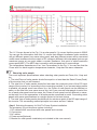
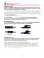
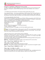
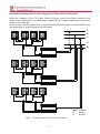
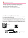
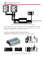
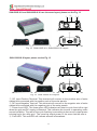
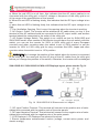
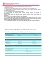
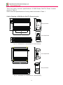
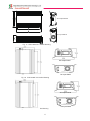
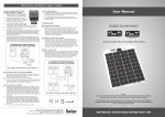
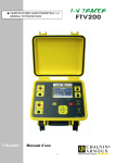
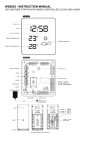
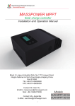
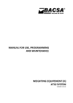
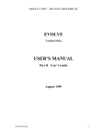
SUN Series Grid Tie Power Inverter
Installation and Operations Manual
SUN-250G
SUN-300G
SUN-500G
SUN-600G
SUN-1000G
SUN-1500G
SUN-2000G
www.chinesegrid.com
Copy Right 2013, All rights reserved
1
Table of Contents
Sunshine Grid Tie Inverter Models ----------------------------------------------------------------------------------3
Model Name Description -------------------------------------------------------------------------------------4
Important Safety Information-------------------------------------------------------------------------------------------4
Safety Instruction----------------------------------------------------------------------------------------------------------4
Instruction of Sunshine Grid Tie Inverter ---------------------------------------------------------------------------5
Advantage of Sunshine Grid Tie System --------------------------------------------------------------------------6
Sunshine Grid Tie Inverter Installation ----------------------------------------------------------------------------7
Installation Procedure ---------------------------------------------------------------------------------------------------8
Step 1 Considering the Total Capacity of the grid tie power system that you need-----------8
Step 2 Choosing Applicable Solar panels for Sunshine Grid Tie Inverter------------------------9
Step 3 Selecting Accessory for Grid Tie Power System installation------------------------------10
Step 4 Selecting Correct Model of Sunshine Grid Tie Inverter-------------------------------------11
Step 5 - Installing Solar Panels to suitable place ------------------------------------------------------13
Step 6 - Installing Sunshine Grid Tie Inverter to suitable place -----------------------------------13
Step 7 - Connecting Sunshine Grid Tie Power System with Cables and Connectors--------13
Step 8 – Grounding the system -----------------------------------------------------------------------------13
Step 9 – Connecting the PV modules after complete from Step1 to Step8---------------------13
Installing larger capacity of grid tie power system----------------------------------------------------------------16
Installing Sunshine Grid Tie Power System to Three Phases Utility Grid----------------------------------18
Starting DIY from small Grid Tie System---------------------------------------------------------------------------19
Layout of Sunshine Grid Tie Power Inverter ---------------------------------------------------------------------20
Technical Date of SUN Series Grid Tie Power Inverter---------------------------------------------------------23
Outline Drawing of SUN Series Grid Tie Power Inverter-------------------------------------------------------24
Weight and Dimension of SUN Series Grid Tie Power Inverter----------------------------------------------25
2
Sunshine Grid Tie Inverter Models
Sunshine grid tie inverters include a series of models, refer to table 1. For more information
of all models, refer to the Sunshine website (http://www.chinesegrid.com).
Table 1, Sunshine Grid Tie Inverter Models
Model Number
Rated Power
(Peak/Continuous)
DC Input
Voltage
AC Output
AC Output
Peak Inverter
Night
Voltage Range Frequency Range Efficiency Power Consumption
SUN-250G-L-U
250W / 225W
10.8V~30V
90V~140V
46Hz~65Hz
90%
0.1W
SUN-250G-M-U
250W / 225W
22V~60V
90V~140V
46Hz~65Hz
91%
0.1W
SUN-250G-L-E
250W / 225W
10.8V~30V
190V~260V
46Hz~65Hz
90%
0.1W
SUN-250G-M-E
250W / 225W
22V~60V
190V~260V
46Hz~65Hz
91%
0.1W
SUN-300G-L-U
300W / 270W
10.8V~30V
90V~140V
46Hz~65Hz
90%
0.1W
SUN-300G-M-U
300W / 270W
22V~60V
90V~140V
46Hz~65Hz
91%
0.1W
SUN-300G-L-E
300W / 270W
10.8V~30V
190V~260V
46Hz~65Hz
90%
0.1W
SUN-300G-M-E
300W / 270W
22V~60V
190V~260V
46Hz~65Hz
91%
0.1W
SUN-500G-L-U
500W / 450W
10.8V~30V
90V~140V
46Hz~65Hz
90%
0.2W
SUN-500G-M-U
500W / 450W
22V~60V
90V~140V
46Hz~65Hz
91%
0.2W
SUN-500G-L-E
500W / 450W
10.8V~30V
190V~260V
46Hz~65Hz
90%
0.2W
SUN-500G-M-E
500W / 450W
22V~60V
190V~260V
46Hz~65Hz
91%
0.2W
SUN-600G-L-U
600W / 540W
10.8V~30V
90V~140V
46Hz~65Hz
90%
0.2W
SUN-600G-M-U
600W /540W
22V~60V
90V~140V
46Hz~65Hz
91%
0.2W
SUN-600G-L-E
600W / 540W
10.8V~30V
190V~260V
46Hz~65Hz
90%
0.2W
SUN-600G-M-E
600W /540W
22V~60V
190V~260V
46Hz~65Hz
91%
0.2W
SUN-1000G-M-U 1000W / 900W
22V~60V
90V~140V
46Hz~65Hz
90%
0.5W
SUN-1000G-H-U 1000W / 900W
45V~90V
90V~140V
46Hz~65Hz
92%
1.5W
SUN-1000G-M-E 1000W / 900W
22V~60V
190V~260V
46Hz~65Hz
90%
0.5W
SUN-1000G-H-E
1000W / 900W
45V~90V
190V~260V
46Hz~65Hz
92%
1.5W
SUN-1500G-H-U
1500W / 1350W
45V~90V
90V~140V
46Hz~65Hz
92%
1.5W
SUN-1500G-H-E
1500W / 1350W
45V~90V
190V~260V
46Hz~65Hz
92%
1.5W
SUN-2000G-H-U
2000W / 1800W
45V~90V
90V~140V
46Hz~65Hz
92%
1.5W
SUN-2000G-H-E
2000W / 1800W
45V~90V
190V~260V
46Hz~65Hz
92%
1.5W
3
Model Name description:
SUN-XXXG-X-X
AC Output Voltage Range, “U” is 90V~140V, “E” is 190V~260V
DC Input Voltage Range, “L” is 10.8V~30V, “M” is 22V~60V, “H” is 45V~90V
“G” is Abbreviation of Grid Tie Power Inverter
The Rated Output Power
The Title Name of Sunshine Products
Some models also have “B” type, “B” means the model has LCD displayer.
For example, the model SUN-1000G-H-E-B is Sunshine grid tie power inverter model that the rated power is
1000W, the DC input voltage range is 45V~90V, the AC output voltage range is 190V~260V, and with LCD displayer
on the panel of the inverter.
Important Safety Information
Read this First !
This manual contains important instructions to follow during installation and maintenance of
Sunshine Grid Tie Inverter.
To reduce the risk of electrical shock, and to ensure the safe installation and operation of the
Sunshine Grid Tie Inverter, the following safety symbols appear throughout this document to
indicate dangerous conditions and important safety instructions.
WARNING! This indicates a situation where failure to follow instructions may be a safety
hazard or cause equipment malfunction. Use extreme caution and follow instructions
carefully.
NOTE: This indicates information particularly important for optimal system operation.
Follow instructions closely.
Safety Instructions
WARNING!
Be aware that the body of the Sunshine Grid Tie Inverters is the heat sink and can
reach a temperature of 80℃ under extreme conditions. To reduce risk of burns, do not touch.
- Perform all electrical installations in accordance with all local electrical codes and the
National Electrical Code.
- Be aware that only qualified personnel should install and/or replace Sunshine Grid Tie
Inverters.
- Do not attempt to repair the Sunshine Grid Tie Inverter; it contains no user serviceable
parts.
If it failed, please contact Sunshine customer service to obtain a RMA number and start the
replacement process. Tampering with or opening the Sunshine Grid Tie Inverter will void the
warranty.
Before installing or using the Sunshine Grid Tie Inverter, please read all instructions and cautionary markings in the technical description and on the Sunshine Grid Tie Inverter and the
PV-array.
4
Introduction of Sunshine Grid Tie Inverter
Sunshine Grid Tie Power Inverter is the world’s most technologically advanced inverter for
use in utility-interactive applications. This manual details the safe installation and operation of the Sunshine Grid Tie Inverter.
This integrated system maximizes energy harvest, increases system reliability, and
implifies design, installation and management.
The small type solar grid tie power inverter can obtain the solar energy from solar panel, and
can tie to the grid through its output cables with no extra equipment. The installation is very
convenient and reliable.
We call the system combining with small solar grid tie inverter and solar panels as ‘SGPV’. The
system includes solar panels and small type grid tie inverter and installation kit. Solar panels
can be mono silicon, polygon silicon, non-crystal film or any other material that can transform
solar energy to electric energy. The power of grid tie inverter should be matched to the power
of solar panels connected. So the power of SGPV is defined by its solar panels, it can be
standardization according to the actual using.
The inverter can be connected to any outlets of utility grid at house. The small grid tie inverter
monitors the volume, frequency and phase of the home utility grid, then produce pure sine
wave AC power that the frequency and phase are as same as the grid's, and the volume is a
bit higher than the grid's, then according to the current controlled PWM, to control the output
power to the grid. The small grid tie inverter just puts out power when the home grid is on.
When the sun shines, the PV panel will produces DC voltage, and the grid tie inverter will
change the DC voltage to AC voltage and puts out power to the home grid. When the total
power of electric apparatus that are using in the house is larger than the output power of the
inverters, these power from the inverters will be consumed in the house, this will slow down
the power meter, otherwise, the difference of the output power of the inverter between the
total used power of the apparatus will go out from the house to the out grid.
Fig 1. A Small Grid Tie Power System with the Sunshine Grid Tie Inverter
5
Advantage of The Sunshine Grid Tie Power System
There are many advantages of SGPV compare with the traditional grid tie power system.
1. Low cost and easy installation - SGPV can make full use of all types of buildings’ surface
that face to the sun in the city as well as fast and easy installation of solar modules and grid tie
inverter. It just needs very low maintenance costs.
2. Free combination - SGPV can be used as a separate grid tie system and can be setup as a
large solar array with many of them. The quantity of SGPV in the array is just according to your
desire. If you are planning to install a grid-tie PV system, in a general way, the solar array and
inverter need to be carefully matched to ensure that the inverter’s voltage and power limits are
not exceeded. When you want to increase more solar panels, and if the total power of the solar
panels exceeds the allocation grid inverter, it is necessary to increase the cost of a grid
inverter.
3. Combination of SGPV does not interact - The traditional solar grid tie system, they offer
units ranging in high power output and these units are modular so you can have multiple units
operating in parallel for large solar arrays. Although, the traditional grid inverter has MPPT
feature (Maximum Power Point Tracking), but the maximum power point is according to the
entire series in terms of solar panels array, if the performance of a piece of solar panels in the
system, for some reason, such as leaves, bird droppings, dust, shadow, etc. and degrades,
the performance of the entire solar power system will decrease.
SGPV has no such disadvantage. If the performance of a piece of solar panels in the system
degrades, this just effects this piece itself, will not affect other SGPV in the system.
4. Improving the efficiency of the entire solar power system – In traditional grid tie system, the
solar panels are connected in series, so the MPPT of the inverter is according to the total
panels in series, not to every panel, but there is difference between every panel, so not every
panel is working at the maximum power, this will reduce the total power of these panel in
series.
But SGPV has no such disadvantage. Because every inverter of SGPV has MPPT function, so
every panel is working at the maximum power, this will increase the efficiency of the entire
system.
5. Low power consumption – Most of the parts in the small grid-tie inverter are digital ICs and
low power MCU, so the power consumption of it is low, though the quantity of grid tie inverters
is increased, but this will not increase the power consumption much of the entire system.
6
Sunshine Grid Tie Inverter Installation
Follow the instructions in this section to install Sunshine Grid Tie Inverters.
WARNING: Before installing the Sunshine Grid Tie Inverter, read all
instructions and cautionary markings in the user manual, on the Sunshine
Grid Tie Inverter, and on the photovoltaic array.
WARNING: Perform all electrical installations in accordance with all local
electrical codes and the National Electrical Code (NEC)
WARNING: Connect the Sunshine Grid Tie Inverter to the electrical utility
grid only after receiving prior approval from the utility company.
WARNING: Be aware that only qualified personnel should connect the
Sunshine Grid Tie Inverter to the electrical utility grid.
WARNING: Be aware that installation of this equipment includes risk of
electric shock. Normally grounded conductors may be ungrounded and
energized when a ground fault is indicated.
WARNING:This unit is provided with fixed trip limits and shall not be
aggregated above 30 kW on a single Point of Common Connection
7
Installation Procedure
Installing Sunshine Grid Tie Power System involves several key steps:
1. Considering the total capacity of the grid tie power system that you need.
2. Choosing applicable solar panels for Sunshine Grid Tie Inverter.
3. Selecting accessory for installation of the Grid Tie Power System .
4. Selecting correct model of Sunshine Grid Tie Inverter.
5. Installing solar panels to suitable place.
6. Installing Sunshine Grid Tie Inverter to suitable place.
7. Connecting Sunshine Grid Tie Power System with cables and connectors.
8. Grounding the system.
9. Completing Sunshine installation map and Connecting the PV modules.
Each of the detailed installation steps in the following sections is numerically
referenced in the installation diagram below.
WARNING: DO NOT connect Sunshine Grid Tie Inverters to the utility grid or
energize the AC circuit(s) until you have completed all of the installation
Step1. Considering the total capacity of the grid tie power system that you need.
The total capacity of the whole grid tie power system is according to your power
consumption in the site that you want to install, or how much power that you want it to feed
to the utility grid. Actually, the volume is just according to your willingness, because when
the total power of electric appliances that are being used in the installation site is larger
than the output power of the grid tie power system, these power from the system will be
consumed in the site, this will slow down the power meter, otherwise, the difference of the
output power from the system between the total used power of the appliances will feed to
the utility grid.
For example, if you want to install a grid tie power system in your house, you could decide
the total power volume according to the total power the appliances that you use in your
house, maybe the consumption of total energy in per day is about 5KWH, then you should
realize the real irradiation time in per day at your site, actually the real irradiation time is an
average result, because it will vary every day according to the climate, just assume the
time is 6 hours, so you can install a 1KW grid tie power system, with this capacity of the
system,it can supply all power consumption in whole year.
When grid tie power system is working, sometimes, there is extra power feed to utility grid
if the power from the grid tie system is larger than the power consumed by the appliances
in your house, and sometimes will not when it is not larger.
Of course, you can install 500W grid tie power system or 2KW grid tie inverter, even more
large capacity or more small capacity grid tie inverter, it doesn’t matter. But if the capacity
is too big, you should consider the volume of AC system of your house can hold the feeded
power.
8
Step2. Choosing applicable solar panels for Sunshine Grid Tie Inverter.
Descripiton of Solar Panel
Solar panel is an array of solar cells, it is an electrical device that converts the energy
of light directly into electricity by the photovoltaic effect. when exposed to light, it can
generate and support an electric current without being attached to any external voltage
source.
Most solar panels consist of solar cells conected in serial. Recently, main solar cells
have two types, Mono and Poly, their performance are almost same.
The main technical data of solar panel including Efficiency, Pmax, Vmp, Imp, Voc, Isc,
etc. For example, the specifications of one type 245W solar panels consist of 60 PCS
156×156 Poly solar cells are shown below.
Module Efficiency: 14.8%
Pmax: 245W
Vmp: 29.4V
Imp: 8.34A
Voc: 36.9V
Isc: 8.68A
Note: These specifications are under Standard Test Conditions(STC).
STC: Irradiance 1000W/m2, Cell temerature 25℃, Air mass AM1.5 according to
EN60904-3.
Module Efficiency is the converting efficiency that the module converts the energy of
light into electricity power.
Pmax is the Maximum Power of solar panels.
Vmp is the Rated Voltage at Pmax.
Imp is the Rated Current at Pmax.
Voc is the Open Circuit Voltage.
Isc is the Short Circuit Current.
Because these specifications are under STC, these specifications also are sensitive
with temperature of surroundings, so should consider the vary of these specification with
temperature. Please check the curves of I-V and Temperature Dependence of Isc, Voc,
Pmax.
9
Fig 2. I-V Curves
Fig 3. Temperature Dependence of Isc, Voc, Pmax
The I-V Curves shown in the Fig. 2 is a solar panel’s I-V curves that the power is 230W.
You can get the information from this I-V curves that different irradiance under sunshine
will get different power from same solar panel, and also different power will be converted
under same irradiance but the output of DC voltage is different, the solar panel just can get
maximum power at one point under a certain irradiance, this point is called maximum
power point(MPP). The MPP also is sensitive with temperature of surroundings.
The temperature dependence of Isc, Voc, Pmax shown in the Fig. 3. You can see that the
Pmax and Voc have negative temperature character, Vmp also has same character.
Choosing solar panels
The most important specifications when selecting solar panels are Pmax,Voc, Vmp and
Isc.
1, The total Pmax of solar panels should be equal to or less than the Rated Power(Peak)
of the inverter that you will connect.
2, The total Voc of solar panels should be less than the maximum point of the DC input
range of the inverter, it is according to the connecting method, if you connect solar panels
in parallel, all panels must have same Voc, the Pmax of each panel can be different or
same, so the total Voc is as same as one Voc, but if you connect solar panels in serial, the
Isc of each solar panel must be same, the Pmax of each panel can be different or same,
so the total Voc is the summation of all solar panels connected in serial. Connecting solar
panels with same specifications in a single system is the best choice.
3, The total Vmp of solar panels should above the minimum point of the DC input range of
the inverter. The connecting method principle is as same as item 2 above.
Step3. Selecting Accessory for Grid Tie Power System installation.
The accessory for grid tie power system including:
1, DC cables will be connected with solar panels and inverters.
2, Connectors.
3, AC cables.
4, Power meter(Optional).
5, Bracket for solar panels installation(not included in this user manual).
10
Selecting DC cables
Before you connect the solar panels to inverter, suitable specification of cables should be
selected. The selection of specifications of the cables is according to the total power of the
solar panels and the connecting method of solar panels.
You should calculate the maximum current that will transit through the cables, we mark it as
Imax. First, calculate the total Pmax of the solar panels that will be consisted of the grid tie
power system, we mark it as TPmax, then calculate the total Vmp of them, we mark it as
TVmp, we also can get total Imp, mark it as TImp, with this, we can get the TImax using a
formula (1) or (2) shown below.
TImp = TPmax/TVmp ------ (1)
or
TImp = Imp×N
------ (2)
N is the parallel number of solar panels
After finish the calculation of Imax, then we can pick suitable cables according to Table 2.
It’s the best that you choose solar cables for outdoor use.
Selecting Connectors
When installing the SGPV system, maybe you should use some connectors for connecting
solar panels and inverter. Most of these connectors are shown as below.
MC4 Connectors
Connectors for parallel connecting
Selecting AC cables
AC cables will be supplied with inverters by our factory, different countries will be supplied
different type AC cables, according to the standard of the area. You should provide the
information to the dealer where you will install the system.
Step4. Selecting Correct Model of Sunshine Grid Tie Inverter.
When finished step1 to step3, and decided the connecting method of the solar panels,
then you can select a correct model of inverter. The input DC voltage range of the
inverter should fit the DC output voltage of the solar panel array, the rated power of the
inverter should also fit the total power of the solar panel array, and the AC output of the
inverter should fit the standard of AC utility grid.
11
Table 2: American Wire Gauge (AWG) Cables / Conductor Sizes and Properties
AWG
0 (1/0)
1
2
3
4
5
6
7
8
9
10
11
12
13
14
15
16
17
18
19
20
21
22
23
24
25
26
27
28
29
30
31
32
33
34
35
36
37
38
39
40
Diameter Diameter
[inches]
[mm]
0.3249
0.2893
0.2576
0.2294
0.2043
0.1819
0.162
0.1443
0.1285
0.1144
0.1019
0.0907
0.0808
0.072
0.0641
0.0571
0.0508
0.0453
0.0403
0.0359
0.032
0.0285
0.0254
0.0226
0.0201
0.0179
0.0159
0.0142
0.0126
0.0113
0.01
0.0089
0.008
0.0071
0.0063
0.0056
0.005
0.0045
0.004
0.0035
0.0031
8.25246
7.34822
6.54304
5.82676
5.18922
4.62026
4.1148
3.66522
3.2639
2.90576
2.58826
2.30378
2.05232
1.8288
1.62814
1.45034
1.29032
1.15062
1.02362
0.91186
0.8128
0.7239
0.64516
0.57404
0.51054
0.45466
0.40386
0.36068
0.32004
0.28702
0.254
0.22606
0.2032
0.18034
0.16002
0.14224
0.127
0.1143
0.1016
0.0889
0.07874
Area
[mm2]
Resistance
[Ohms /1000 ft]
53.5
0.0983
42.4
0.1239
33.6
0.1563
26.7
0.197
21.2
0.2485
16.8
0.3133
13.3
0.3951
10.5
0.4982
8.37
0.6282
6.63
0.7921
5.26
0.9989
4.17
1.26
3.31
1.588
2.62
2.003
2.08
2.525
1.65
3.184
1.31
4.016
1.04
5.064
0.823 6.385
0.653 8.051
0.518 10.15
0.41
12.8
0.326 16.14
0.258 20.36
0.205 25.67
0.162 32.37
0.129 40.81
0.102 51.47
0.081 64.9
0.0642 81.83
0.0509 103.2
0.0404 130.1
0.032 164.1
0.0254 206.9
0.0201 260.9
0.016 329
0.0127 414.8
0.01
523.1
0.00797 659.6
0.00632 831.8
0.00501 1049
Resistance
[Ohms/ km]
0.322424
0.406392
0.512664
0.64616
0.81508
1.027624
1.295928
1.634096
2.060496
2.598088
3.276392
4.1328
5.20864
6.56984
8.282
10.44352
13.17248
16.60992
20.9428
26.40728
33.292
41.984
52.9392
66.7808
84.1976
106.1736
133.8568
168.8216
212.872
268.4024
338.496
426.728
538.248
678.632
855.752
1079.12
1360
1715
2163
2728
3440
12
Max Current Max Frequency
[Amperes]
for 100% skin depth
150
119
94
75
60
47
37
30
24
19
15
12
9.3
7.4
5.9
4.7
3.7
2.9
2.3
1.8
1.5
1.2
0.92
0.729
0.577
0.457
0.361
0.288
0.226
0.182
0.142
0.113
0.091
0.072
0.056
0.044
0.035
0.0289
0.0228
0.0175
0.0137
250 Hz
325 Hz
410 Hz
500 Hz
650 Hz
810 Hz
1100 Hz
1300 Hz
1650 Hz
2050 Hz
2600 Hz
3200 Hz
4150 Hz
5300 Hz
6700 Hz
8250 Hz
11 k Hz
13 k Hz
17 kHz
21 kHz
27 kHz
33 kHz
42 kHz
53 kHz
68 kHz
85 kHz
107 kHz
130 kHz
170 kHz
210 kHz
270 kHz
340 kHz
430 kHz
540 kHz
690 kHz
870 kHz
1100 kHz
1350 kHz
1750 kHz
2250 kHz
2900 kHz
Step5. Installing Solar Panels to suitable place.
Installing the solar panels of the SGPV to suitable location that sunshine can irradiate on
them, there must have no shadow, the installation direction of the solar panels should be
according to the geography position that the system will be installed, different position should
has different installation direction, the principle is to get maximum irradation in all the year
round.
Warning: Ensure that there is no shadow at the location that solar panels will be installed,
because even the shadow just covers only one cell of solar panel, maybe will cause total
system stop to produce power.
Warning: Ensure using strong braket to fix the solar panels to avoid the danger under
high wind.
Step6. Installing Sunshine Grid Tie Inverter to suitable place.
Place the Sunshine Grid Tie Inverter on a surface protected from direct sunlight, high
temperatures, and water. The inverter requires at least 150mm of clearance around itself for
ventilation. The inverters are for indoor use, can’t use at outdoor. You can use screws to fix
the inverter to the surface, because some models of Sunshine grid tie inverter have fans on
the bottom cover, so the surface should be flat.
Step7. Connecting the Sunshine Grid Tie Power System with Cables and Connectors
After finished from Step1 to Step6, you should connect the solar panels and inverters with cables
and connectors to integrate the Sunshine Grid Tie System.
Step8. Grounding the system.
Route a continuous GEC through each of the solar panels to the NEC approved AC grounding
electrode. The racking and module could be grounded to this conductor using a crimp
connection. An alternative method would be to connect the grid tie inverters to the grounded
racking using a grounding washer approved for the racking. The ground wire of the AC cables
is connnected to the housing of inverter when the AC cables is connected to the inverters, so
when the AC plug is inserted to the socket of AC outlet of utility grid in the house, the ground pin
of the socket must be connected to the Earth ground.
Step9. Connecting the PV modules after complete from Step1 to Step8.
Warning: If you will connect the PV modules to the inverter under sunshine, you should cover
the modules with no transparent material like black cloth, if the modules have been connected in
serial, just cover one module, actually, just need to cover one cell of the module, but if the
modules have been connected in parallel, you should cover one module of every branch, also
just need to cover one cell when you cover a module.
Covering the modules under sunshine just in order to avoid the sparkle when connect the cables.
13
Example of Installation of 1KW grid tie power system
In order to explain the installing operation, we assume that there is a house that the usual
electricity consumption is about 5KWH per day, and the real irradiation time is about 5
hours.
1, Considering the total capacity of the grid tie power system that you need.
As we stated at Step1, we can get a result that a 1kW Sunshine Grid Tie Power System is
suitable for this house, so we will establish a 1KW gird tie power system step by step, we
also assume that we will install the system in the house where the utility grid is 230V/50Hz.
2, Choosing applicables Solar Panels.
Because the most popular solar panels are 240Wp~250Wp poly panels with 60 PCS solar
cells, so choosing this kind type panels will be more economical. The system is 1KW power
system, so we should use 4 PCS 240Wp to 250Wp solar panels.
Most of this kind type solar panels have similar specification shown below.
Module Efficiency:14.8%
Pmax:245W
Vmp:29.4V
Imp:8.34A
Voc:36.9V
Isc:8.68A
so use 4 PCS of this type panels, we can get total power:
TPmax = 245Wp×4 = 980Wp
from these solar panels, it is suitable for 1KW SUN-1000G model inverter.
Notes: The Pmax specification of solar panel is under STC, the actual power is variational
according to the irradiation on the panel and the temperature surroundings. The real output
power can’t reach Pmax at most time in whole day.
3,Selecting Accessory for Grid Tie Power System installation.
Because we should connect 4 PCS solar panels to Sunshine Grid Tie Inverter, so some
connectors are necessary. Consider of the Voc, Vmp and Isc, we choose some MC4
connectors and some connectors for parallel connecting.
For the choice of DC cables, we should consider about the connecting method of solar panels,
there are two methods can be choosed.
Method 1: Connecting the 4 panels in parallel, so the maximum DC current will be
TImp = TPmax/TVmp = 980W/29.4V = 33.3A
or
TImp = Imp × 4 = 8.34A × 4 = 33.3A
According to the Table 2, AWG6 Cables should be choosed.
Method 2:Connecting 2 panels in serial consist as a pair, so 4 panels can be gotten 2 pairs,
TImp = TPmax/TVmp = 980W/58.8V = 16.7A
or
TImp = Imp × 2 = 8.34A × 2 = 16.7A
So according to the Table 2, AWG9 cables should be choosed.
Because the DC cables will be more expensive if the diameter is big, considering about this
matter, the method that can use smaller diameter cables will be a good choice.
14
4, Selecting correct model of Sunshine Grid Power Inverter.
Because maybe there will be several methods of connecting solar panels to Sunshine Grid
Tie Inverter, different connecting method maybe should use different model inverter. In this
case, there are two connecting methods.
With method 1, because all panels are connected in parallel, so we can know that the
TVoc(total Voc of the solar panels) will be same as Voc of one panel, and the TVmp also
is same as Vmp of one panel. So we can get the specifications of the solar panels array
with solar panels connected each other.
TPmax:245W×4
TVmp:29.4V
TImp:8.34A×4
TVoc:36.9V
TIsc:8.68A×4
From these specification, we should to use SUN-1000G-M-E. This is because, the DC input
voltage range of this model is 22V to 60V, so the TVoc and TVmp is in the DC input voltage
range
With method 2, we also can get the specifications of the solar panels array.
TPmax:245W×4
TVmp:29.4V×2
TImp:8.34A×2
TVoc:36.9V×2
TIsc:8.68A×2
From these specifications, we should to use SUN-1000G-H-E. This is because, the DC
input voltage range of this model is 45V to 90V, so the TVoc and TVmp is in the DC input
voltage range.
The two connecting method diagrams are shown in Fig.4 and Fig.5 below.
4 × 245Wp Solar Panels
Connected in parallel
Outlet of Utility Grid
DC Input Panel
SUN-1000G-M-E
Fig. 4
AC Output Panel
1KW Sunshine Grid Tie Power System Connected With Method 1
15
4 × 245Wp Solar Panels
2 Panels Connected in Serial
Constitudes a Pair of Panel
2 Pairs Connected in Parallel
Outlet of Utility Grid
SUN-1000G-H-E
AC Output Panel
DC Input Panel
Fig. 5
1KW Sunshine Grid Tie Power System Connected With Method 2
Comparing the connected method in Fig.4 and Fig5, we can see that method 2 is the good
choice, because with method 1, the DC cables is more thick, so it is more expensive, and
three pairs of connectors for parallel connecting plus three pairs of MC4 connectors should
be used.
But with method 2, the DC cables is thin, and just a pair of connectors for parallel connecting
and a pair of MC4 connector should be used.
Installing larger capacity of grid tie power system.
Sometimes, maybe you are willing to install larger capacity of grid tie inverter in your house,
this is also very easy to operate. For example, you want to install 2KW grid tie power system,
you can install two 1KW grid tie power systems as shown in Fig.5, two AC output cables
should be all connected to the AC outlet of the utility grid with the plugs.
The diagram of the 2KW grid tie system with two 1KW sytem are shown in Fig. 6, we call this
kind system as “Stackable System”.
16
4 × 245Wp Solar Panels
4 × 245Wp Solar Panels
2 Panels Connected in Serial
Constitudes a Pair of Panel
2 Panels Connected in Serial
Constitudes a Pair of Panel
2 Pair Connected in Parallel
2 Pair Connected in Parallel
SUN-1000G-M-E
Fig.6
SUN-1000G-M-E
2KW Grid Tie Power System Consist of Two 1KW Grid Tie Power System Stacked
You can install any capacity of grid tie power system by stack small grid tie power systems.
For example, if you want to install 12KW grid tie power system, there are many choices, you
can stack six 2KW grid tie power systems, or twelve 1KW gird tie systems, or stack
twenty-four 500W grid tie power systems, or stack fourty-eight 250W grid tie power system,
even you can mix different capacity grid tie power systems to gain large capacity system.
WARNING: Don’t Connect the DC input Terminals of one Sunshine Grid Tie Power
Inverter to another’s. If so, neither of the inverters can find the correct maximum power
point(MPP), this will reduce the efficiency of the system. Shown in Fig.7.
Solar Panel Array
×
SUN-1000G-H-E
SUN-1000G-H-E
Fig.7 Error Connecting of DC Input Terminals
17
Installing Sunshine Grid Tie Power System to Three Phases Utility Grid.
When the Capacity of Gird Tie Power System is larger, intall all the power system to one
phase of the utility grid is not reasonable, maybe this will cause unbanlance of the three
phase of the utility grid.
In this section, we will explain how to install Sunshine Power System to three phases utility
grid seperately in order to balance the fed power.
A
B
C
G
N
A/B/C: 3 phases
N:
Neutral
G:
Ground
Fig.8
Three Phases Grid Tie Power System
18
For example, installing a 3KW grid tie power system to three phase utility grid.
The diagram is shown in Fig. 8, we seperate 3KW power sytem to three power system units,
every unit has 1KW power. Connecting every system unit to different phase, this can
balance all grid tie power to three phases of the utility grid.
Fllow this way, you can install more large grid tie power system to three phases, just
seperate the whole power system to three equal power system units.
Starting DIY from small grid tie power system.
If you never have experience of installing grid tie power system before, you can start DIY(do
it by yourself) from small grid tie power system.
The smallest power of SUN series grid tie power inverter is SUN-250G, this is a small power
inverter that the rated output power is 225W, and the peak power can reach 250W, so you
can establish a small capacity grid tie power system with this model inverter and a big solar
panel or two smaller solar panels, the total Pmax of solar panels should be less than 250Wp.
it’s very easy to install this kind small system, just need DC cables and few connectors to
connect the system. For example, you can choose a 245Wp solar panel or two 120Wp solar
panels to connect with SUN-250G inverter.
250Wp Solar Panel
Outlet of Utility Grid
SUN-250G-X-X
DC Input Panel
Fig.9
AC Output Panel
Installing a 250W gird tie power
system with a SUN-250G grid tie
power inverter and a 250Wp solar
panel.
250W grid tie power system with one solar panel
19
2×120Wp Solar Panel
Outlet of Utility Grid
SUN-250G-X-X
Installing a 250W gird tie power
system with a SUN-250G grid tie
power inverter and two 125Wp
solar panels.
DC Input Panel
Fig.10
AC Output Panel
250W grid tie power system with two solar panels
It doesn’t matter that you connect small power solar panels like 60Wp, 85Wp or other power
to the inverter, the specification of total panels must meet the specification that you choose
according to the principle that mentioned in this user manual .
Layout of Sunshine Grid Tie Power Inverter
SUN-250G-X-X and SUN-300G-X-X have same layout, please see the Fig. 11.
①② ③ ④
⑤
DC Input Panel
⑥
AC Output Panel
Fig. 11 SUN-250G-X-X, SUN-300G-X-X Layout
20
⑦
SUN-500G-X-X and SUN-600G-X-X have the same layout, please see the Fig. 12
⑤
④③
①②
DC Input Panel
⑥
AC Output Panel
Fig. 12 SUN-500G-X-X, SUN-600G-X-X Layout
SUN-1000G-X-X layout, please see the Fig. 13
⑤
④③
①②
DC Input Panel
⑥
AC Output Panel
Fig. 13 SUN-1000G-X-X Layout
①. DC Input Positive Terminal. This terminal will connect to the positive wire of solar
cables that connected with the positive pole of the solar panels.
②. DC Input Negative Terminal. This terminal will connect to the negative wire of solar
cables that connected with the negative pole of the solar panels.
③. Power Level LED. The three green LED indicators will start to cycle from left to right
when the grid and DC supply is detected. This indicates the inverter is operating under
normal condition. The rate of the cycle flashing is according to how much output power
is being fed to the utility grid . The more big output power is, the more fast the rate is.
④. Fault LED. This red LED will indicate several informations:
21
a) When the red LED is on all time, this indicates that the AC output cables is not
connected with the utility grid, or the AC voltage or frequence of the uitlity grid is out
of the range of the specifications of the inverter.
b) When this red LED is flashing slowly, this indicates that the DC input voltage is too
low.
c) when this red LED is flashing fastly, this indicates that the DC input voltage is too
high.
⑤. Fan Ventilation Opening. Don’t cover this opening when the inverter is working.
⑥. AC Output Outlet. The inverter will be attached a AC cable when you buy it, one
terminal of this AC cables should be connected to the AC output outlet, and another
terminal should be connected to the outlet of the utiltiy grid.
⑦. AC Output Voltage Switch. This switch is an unique set just for SUN-250G and
SUN-300G model, other models of SUN Series inverter have no such switch, with this
switch, you can set the inverter for 220V to 240V utility grid of many European
countries and other countries when the switch is set to 230V position or set the
inverter for 100V to 120V utility grid for many countries like USA, Japan and other
countries when the switch is set to 115V position.
WARNING: Don’t change the position of this switch when the inveter is connected
to the utility grid. You must pull out the AC plug of the AC cables from the utility grid
before you change the position of the switch, otherwise, the inverter will be damaged.
SUN-1500G-X-X / SUN-2000G-X-X With LCD Displayer layout, please see the Fig. 14
Fig. 14 SUN-1500G-X-X /SUN-2000G-X-X Layout
①. DC Input Positive Terminal. This terminal will connect to the positive wire of solar
cables that connected with the positive pole of the solar panels.
②. DC Input Negative Terminal. This terminal will connect to the negative wire of solar
cables that connected with the negative pole of the solar panels.
③. LCD Displayer. LCD Displayer has severial functions:
1. Electric parameters measurement function (voltage, current active power, and
electric energy).
22
2. Running time function (record load cumulative working hours).
3. Backlight function.
4. Power down data save function (save the number of kWh, operation time).
5. Large screen LCD display (display voltage, current, active power, electric energy,
cumulative running time)
④. LCD Displayer Function Selecting Buttons.
UP: Short press will display power, electric energy, current and voltage in
anti-sequence.
DOWN: Short press will display power, electric energy, current and voltage in
sequence.
BACK LIGHT: Short press will open or close backlight.
⑤. AC Output Outlet.The inverter will be attached a AC cable when you buy it, one
terminal of this AC cables should be connected to the AC output outlet, and another
terminal should be connected to the outlet of the utiltiy grid.
⑥. Fan Ventilation Opening. Don’t cover this opening when the inverter is working.
Technical Data of SUN Series Grid Tie Power Inverter
Table 3. Common Specifications for SUN Series Grid Tie Power Inverter
INPUT DATA (DC)
SUN-XXXG-L-X
SUN-XXXG-M-X
SUN-XXXG-H-X
Maximum Input DC Voltage
30 V
60 V
90 V
Peak power Tracking Voltage
14 V - 28 V
26V - 54 V
50 V - 82 V
Operating DC Voltage Range
10.8 V - 30 V
22 V - 60 V
45 V - 90 V
Peak Inverter Effeciency
10.8 V - 30 V
22 V - 60 V
45 V - 90 V
OUTPUT DATA (AC)
SUN-XXX-X-E
SUN-XXX-X-U
Nominal Voltage/Range
230V/190V-260V
115V/90V-140V
Frequency Range
46Hz~65 Hz
46Hz~65 Hz
Power Factor
>0.95
Output Waveform
Pure Sine Wave
>0.95
Pure Sine Wave
SUN-XXX-X-X
CHARACTERISTIC DATA
MPPT Effeciency
99%
Over Current Protection
Yes
Over Temperature Protection
Yes
Reverse Polarity Protection
Yes
Anit-Island Protection
Yes
Stackable
Just for AC Output
Operating Temperature Range
-20℃~ 45℃
Storage Tmeperature Range
-40℃~ 65℃
23
There are some common specifications of SUN Series Grid Tie Power Inverter
shown in Table 3.
Other electrical specifications of every model are listed in Table 1.
Outline Drawing of SUN Series Grid Tie Power Inverter
DC Input Panel
AC Output Panel
Fig. 15 SUN-250G-X-X / SUN-300G-X-X Outline Drawing
AC Output Panel
DC Input Panel
Fig. 16 SUN-500G-X-X / SUN-600G-X-X Outline Drawing
24
AC Output Panel
DC Input Panel
Fig. 17 SUN-1000G-X-X Outline Drawing
AC Output Panel
DC Input Panel
Fig. 18 SUN-1500G-X-X Outline Drawing
AC Output Panel
DC Input Panel
Fig. 19 SUN-2000G-X-X Outline Drawing
25
Weight and Dimension of SUN series Grid Tie Power Inverter
Model
SUN-250G-X-X
SUN-300G-X-X
SUN-500G-X-X
SUN-600G-X-X
SUN-1000G-X-X
SUN-1500G-X-X
SUN-2000G-X-X
Net Weight
1.6Kg
3.6Kg
4.0Kg
4.3Kg
5.2Kg
Gross Weight
1.8Kg
3.8Kg
4.8Kg
5.0Kg
6.0Kg
Dimension(Package) 245mm×215mm×85mm
400mm×270mm×140mm
335mm×270mm×140mm
470mm×290mm×140mm
520mm×310mm×160mm
Troubleshooting
After all installation step described throughout this manual, Qualified personnel can use the
following troubleshooting steps if the Sunshine Grid Tie Power System does not operate
correctly.
WARNING: Do not attempt to repair the Sunshine Grid Tie Inverter, it contains no
user-serviceable parts. If it fails, please contact Sunshine customer service to
obtain an RMA number and start the replacement process.
Status LED Indications and Error Reporting
Each grid tie inverter has a red LED that indicates status as follows:
a) When the red LED is on all time, this indicates that the AC output cables is not
connected with the utility grid, or the AC voltage or frequence of the utility grid is out of
the range of the specification of the inverter.
Please check the AC cables and the outlet of the utility grid, you can use a multi-meter
to measure the AC voltage or frequency, then you can judge what’s wrong about the AC
output.
b) When this red LED is flashing slowly, this indicates that the DC input voltage is too low
or the DC connection is not good. You should measure the output voltage of solar panel
or solar panel array.
c) when this red LED is flashing fastly, this indicates that the DC input voltage is too high,
you should adjust the connecting method according to the descripition in this manual.
WARNING: Never disconnect the DC wire connectors under load. Ensure that no
current is flowing in the DC wires prior to disconnecting. An opaque covering may be
used to cover the module prior to disconnecting the module.
26