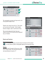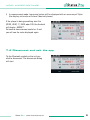
1
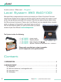
Precision Level System
Instruction Manual
ExterNnaTlROL!
CO
BA 1044 E 10/13
Another fine solution by
Instruction Manual – English
Level System (BG 840100)
We would like to congratulate you on the purchase of your Status Pro µLevel Precision
Level System. Before initial usage you should carefully read the safety instructions as well
as the user guidelines contained in this manual. We wish you every success when using
this Measurement Instrument. Please note: User Manuals can be amended when improvements or changes to the product range have been carried out.
Use the link below to make sure you have the most up to date
version of your User Manual: www.statuspro.com.
The System includes the following:
•
•
•
•
1 x BT 840100
1 x BT 840110
1 x BT 840120
1 x BT 840170
µLevel single
Case for µLevel
Foam inlay for µLevel Case
Optional: Software Smartlevel Pro + Cable Kit
Please make sure that your system is complete
and all components are in good condition.
Content
1. INTRODUCTION . . . . . . . . . . . . . . . . . . . . . . . . . . . . . . . . . . . . . . . . . . . . . . . . . . . . . . . . . . . . . . . 4
2. NOTES ON SAFETY . . . . . . . . . . . . . . . . . . . . . . . . . . . . . . . . . . . . . . . . . . . . . . . . . . . . . . . . . . . . 4
2.1 Standards . . . . . . . . . . . . . . . . . . . . . . . . . . . . . . . . . . . . . . . . . . . . . . . . . . . . . . . . . . . . . . . 4
2.2 Advice on batteries / rechargeable cells . . . . . . . . . . . . . . . . . . . . . . . . . . . . . . . . . . . . 5
2.3 Instrument care . . . . . . . . . . . . . . . . . . . . . . . . . . . . . . . . . . . . . . . . . . . . . . . . . . . . . . . . . . 5
2.4 Calibration . . . . . . . . . . . . . . . . . . . . . . . . . . . . . . . . . . . . . . . . . . . . . . . . . . . . . . . . . . . . . . . 6
2
Status Pro – µLevel Instruction manual
CONTENT
2.5 Liability Exclusion . . . . . . . . . . . . . . . . . . . . . . . . . . . . . . . . . . . . . . . . . . . . . . . . . . . . . . . . . 6
3. GETTING STARTED . . . . . . . . . . . . . . . . . . . . . . . . . . . . . . . . . . . . . . . . . . . . . . . . . . . . . . . . . . . . . 7
3.1 Batteries / rechargeable cells . . . . . . . . . . . . . . . . . . . . . . . . . . . . . . . . . . . . . . . . . . . . . . 7
3.2 Button panel . . . . . . . . . . . . . . . . . . . . . . . . . . . . . . . . . . . . . . . . . . . . . . . . . . . . . . . . . . . . . 7
3.3 Display . . . . . . . . . . . . . . . . . . . . . . . . . . . . . . . . . . . . . . . . . . . . . . . . . . . . . . . . . . . . . . . . . . 8
4. OPERATION GUIDE . . . . . . . . . . . . . . . . . . . . . . . . . . . . . . . . . . . . . . . . . . . . . . . . . . . . . . . . . . . . 12
4.1 Temperature Constant before Using . . . . . . . . . . . . . . . . . . . . . . . . . . . . . . . . . . . . . . . . 12
4.2 The Meaning of the Readings Displayed at Measuring Mode . . . . . . . . . . . . . . . . . 12
4.3 Level Inspection and Adjustment for Working Surface . . . . . . . . . . . . . . . . . . . . . . . . 13
4.4 Straightness and Flatness Measurement . . . . . . . . . . . . . . . . . . . . . . . . . . . . . . . . . . . 14
4.5 Use the Store Function of the Level Meter . . . . . . . . . . . . . . . . . . . . . . . . . . . . . . . . . . 15
4.6 Measurement Connecting with Computer . . . . . . . . . . . . . . . . . . . . . . . . . . . . . . . . . . . 15
5. ADJUSTMENT OF THE APPARATUS . . . . . . . . . . . . . . . . . . . . . . . . . . . . . . . . . . . . . . . . . . . . . 16
5.1 Relative Zero Setting . . . . . . . . . . . . . . . . . . . . . . . . . . . . . . . . . . . . . . . . . . . . . . . . . . . . . 16
5.2 Absolute Zero Setting . . . . . . . . . . . . . . . . . . . . . . . . . . . . . . . . . . . . . . . . . . . . . . . . . . . . 16
5.3 Scale of the Apparatus Displayed Value . . . . . . . . . . . . . . . . . . . . . . . . . . . . . . . . . . . . 17
5.4 Renew the Leave Factory Settings . . . . . . . . . . . . . . . . . . . . . . . . . . . . . . . . . . . . . . . . . 18
6. TECHNICAL DATA . . . . . . . . . . . . . . . . . . . . . . . . . . . . . . . . . . . . . . . . . . . . . . . . . . . . . . . . . . . . . 19
7. µLEVEL ANDROID SOFTWARE (OPTIONAL) . . . . . . . . . . . . . . . . . . . . . . . . . . . . . . . . . . . . . . 20
7.1 Software Installation . . . . . . . . . . . . . . . . . . . . . . . . . . . . . . . . . . . . . . . . . . . . . . . . . . . . . 20
7.2 µLevel registration . . . . . . . . . . . . . . . . . . . . . . . . . . . . . . . . . . . . . . . . . . . . . . . . . . . . . . . 20
7.3 Differential (Delta)- and Rightangles- resultant . . . . . . . . . . . . . . . . . . . . . . . . . . . . . . 22
7.4 Disconnect and exit the app . . . . . . . . . . . . . . . . . . . . . . . . . . . . . . . . . . . . . . . . . . . . . . 23
8. SMARTLEVEL PRO SOFTWARE (OPTIONAL) . . . . . . . . . . . . . . . . . . . . . . . . . . . . . . . . . . . . . . 24
8.1 Basic Setup . . . . . . . . . . . . . . . . . . . . . . . . . . . . . . . . . . . . . . . . . . . . . . . . . . . . . . . . . . . . . 24
8.2 Program Operating . . . . . . . . . . . . . . . . . . . . . . . . . . . . . . . . . . . . . . . . . . . . . . . . . . . . . . 25
8.3 Measuring icon . . . . . . . . . . . . . . . . . . . . . . . . . . . . . . . . . . . . . . . . . . . . . . . . . . . . . . . . . 26
8.4 Measuring object . . . . . . . . . . . . . . . . . . . . . . . . . . . . . . . . . . . . . . . . . . . . . . . . . . . . . . . . 27
9. PRODUCTS UND SERVICES . . . . . . . . . . . . . . . . . . . . . . . . . . . . . . . . . . . . . . . . . . . . . . . . . . . . 33
Status Pro – µLevel Instruction manual
3
INTRODUCTION
1. Introduction
µLevel is produced in Far East with the quality standard ISO 9001 since 1993. It is a high
accuracy measuring product adopting sensitive capacitance sensor, as well as using SCM
as controller. It is widely used for the inspection of the flatness, straightness of products,
installation and adjustment of precision machine tools, Machining Centers, Three
Coordinates Measuring Machines. Meanwhile its measured data could be input computer
directly, cooperating with measuring software, the flatness and straightness of products
could be measured automatically, and calculated measuring result and graph could be
output and printed. Ergonomical Design, self-contained functions, will bring your measuring work beat all surprise and kilter.
As this Digital Level Meter has a lot of functions, carefulness reading of the operation
manual before using could guide you making full use of the various functions.
2. Notes on safety
2.1 Standards
0678
R&TTE Guideline 1999/5/EC:
– EN 300 328 V1.7.1 (2006-10)
EMC:
– EN 301 489-1 V1.8.1 (2008-04)
– EN 301 489-17 V2.1.1 (2009-05)
– EN 61000-6-2 (2005)
– EN 61326-1:2006
Health and safety:
– EN 50371:2002
– EN 60950-1:2006 + A11:2009 + A1:2010 (EN 60950-1:2011-01)
and/or IEC 60950-1:2005 (2nd Edition) + A1:2009
4
Status Pro – µLevel Instruction manual
NOTES ON SAFETY
2.2 Advice on batteries / rechargeable cells
If the equipment is being stored for a longer period of time or being powered using Mains,
then the batteries should be removed to prevent damage of the instrument through
leakage.
When using rechargeable cells always observe the specific charging procedures for the
cells.
Rechargeable cells can be recharged around 1000times when treated correctly, but there
is no guarantee!
Caution!
Do not try to recharge normal batteries. Do not expose batteries
or rechargeable cells to fire or excess heat (Danger of explosion).
Do not mix batteries and rechargeable cells.
Always use batteries and cells of the same kind.
Do not mix old and new batteries or cells.
Note
Help to protect the environment! Empty batteries do not belong in
the household waste disposal system. Only deposit empty or
damaged cells at a collection point specially designed for this
purpose.
2.3 Instrument care
Your measurement instrument is designed for use in an industrial environment and can
withstand water splashes or light spray as well as dust. Clean the equipment using a soft
cotton cloth and a mild soap solution. Laser apertures as well as well as sensor areas
should only be cleaned using a soft, dry and dust-free cloth. Do not use paper towels to
clean glass surfaces as they could scratch. Avoid contact with grease, oil or oil-based
solutions when handling the equipment.
Status Pro – µLevel Instruction manual
5
NOTES ON SAFETY
2.4 Calibration
To guarantee measurement accuracy, and reliable operation of your Status Pro
Measurement System, it is of utmost importance that the recommended service intervals
be adhered to. The System should be checked for serviceability, and re-calibrated by the
Status Pro workshops every 12 months.
Within the scope of the service checks, the complete system will also be examined for
possible wear or damage, as well as receiving any software updates.
The date of the next service check for your equipment is stamped on the Status Pro calibration sticker.
To ensure trouble-free processing of the service and calibration checks, simply fill in the
form you will find using the following link www.statuspro.com.
Advice
To be able to identify the equipment when seeking advice always
quote the serial number of the equipment. The Manufacturer does
not accept any responsibility for damage incurred through incorrect
maintenance carried out by non-authorised personnel.
2.5 Liability Exclusion
The Status Pro GmbH does not accept responsibility for damage incurred through incorrect use or handling of the equipment. To ensure correct usage, a founded knowledge of
the equipment is essential. It is of the utmost importance that you read and understand
the Handbook!
No responsibility will be accepted for damage incurred through ignorance or disregarding
of the operating instructions.
6
Status Pro – µLevel Instruction manual
GETTING STARTED
3. Getting started
3.1 Batteries / rechargeable cells
1. Open the cover of the battery storehouse under the handle.
2. Put in 4 pieces of “AA”5# battery as per the positive and negative
poles marked on the cover of the battery storehouse.
3. Close the cover and check the battery installation have been OK.
Reminding:
• When
begin to blinking, all of the batteries should be replaced.
• New batteries could not be mixing used with old batteries.
• If the apparatus will not be used for a long time, the batteries
should be taken out in case of the leakage of the batteries rust
other components, which may cause the apparatus can not work.
• New batteries could not be mixing used with old batteries.
3.2 Button panel
Induction Control Panel
Display
Handle
Power on-off
Data transmission socket
Storehouse for batteries
Measuring base
Housing
SCL / RST key
Control box
Status Pro – µLevel Instruction manual
7
GETTING STARTED
3.3 Display
Measurement with 1µm/m resolution
Measurement with 10µm/m resolution
Zero Setting
Voltage
Temperature
Read stored data
Delete stored data
Scale
Restoration
Serial number
Serial number for current data
The last data stored
Display of measurement readings
Power low
Tilt direction display: right side high
Tilt direction display: left side high
Minus display
Radix point
Measuring unit: second
Start-up Inspection:
Switch on the power, displayer will show measuring
phase position. The measuring
unit will be same as what it was before the apparatus being switched off.
Display for measuring unit in mm
8
Display for measuring unit in inch
Status Pro – µLevel Instruction manual
GETTING STARTED
Touch gently the Mode key
and adjust it to voltage , the LED displayer will show current voltage.
If the voltage is lower than 4 V, Low Voltage warning
will flash.
Reminding
➜ If no shows or show abnormally after the power being switched on, please switch off
the power at once. After eliminate the trouble, start-up could be done.
Touching Key
After the apparatus is switched on, touch gently Mode key
or
LED displayer will show the following list: II, I, Zero Setting, Voltage,
Temperature, Reading, Delete.
, the
Fine adjustment, zero setting; reading, reset (see Function Choice).
Touch the
button, radian unit (mm/m) and angle unit (second) could be
transformed. This function could only be available at measuring phase
and
, no use at other measuring phase.
(1) When choose radian unit to measure, it display the measuring unit “mm/m”.
It expresses the gradient height difference at length of 1 meter. In the practice
inspection, as the span of the used stride bridge is different, the reading a´I for every
inspected point at the E-level meter could be transformed to line value ai (µm) by the
following formula
ai = 1000TL a´I (µm)
T ------ Resolution of the E-level meter (µm)
L ------ Span of stride bridge (mm)
(2) When choose angle unit to measure, LED will show the angle value (˝).
Status Pro – µLevel Instruction manual
9
GETTING STARTED
Function Choice
After the apparatus is switched on, touch gently Mode key
different functions.
or
could choose
Measuring Phase
This is a high precision measuring phase. The resolution of measuring phase II of WL11 Digital Level Meter is 0.001mm/m, suit to
inspect the flatness, straightness of products with precision grade “00”. The resolution of
measuring phase II of WL10 Digital Level Meter is 0.005mm/m, suit to inspect the flatness,
straightness of products with precision grade “0”.
Measuring Phase
This is relative lower precision measuring phase. The resolution of
measuring phase I of WL11, WL10, WL9 Digital Level Meter is
0.01mm/m, suit to inspect the flatness, straightness of products with
precision grade“1”.
Reminding
➜ Different resolutions of different measuring phase suit to different accuracy
inspections. Please choose proper product and measuring phase accordingly.
➜ The higher measuring phase limit the temperature and environment strictly.
If environment and temperature could not be ensured as requested, the apparatus may
be not stabilized.
Zero Setting
Being at this mode, press button
and
, the Level Meter
zero position could be set.
(1) At the working surface being inspected, set Zero at any position (relative zero position).
(2) Absolute zero setting
(3) Nice zero setting could be available by pressing the number descending or ascending.
Reminding
➜ Regarding to the detailed process of zero setting for Digital Level Meter, please read
Segment “Apparatus Adjustment” on page 16.
Voltage
Function of measuring the power voltage automatically. LED
displayer shows the voltage (V) of the batteries being in use. When
the voltage is lower than 4V, low voltage warning
will flash.
10
Status Pro – µLevel Instruction manual
GETTING STARTED
Temperature
Function of measuring the temperature automatically. LED displayer
shows the current environment temperature (°C).
Reading
At this function, press “gentle adjust zero setting”, the data stored in
the E-level meter and sequence number could be shown in turn. This
E-level meter could store maximum 999 data. When the last datum is displayed, the mark
will occur.
Cancellation Mode
At this mode, press button
three times, all of the data stored
in the E-level meter will be cancelled.
Scale Mode
Plug the instrument screwdriver into the small hole at left of the Elevel meter, press once SCL/RST button, LED will show , then
scale at Small Angle Inspection Instrument.
Reminding
➜ The E-level meter need to be scaled at Small Angle Inspection Instrument by metrology
unit, could not be scaled by end-user unbending, in case effect the measuring
accuracy of the E-level meter.
Restoration
Plug the instrument screwdriver into the small hole at left of the Elevel meter, press twice SCL/RST button, LED will show , touch
button and confirm.
Reminding
➜ After the restoration of the E-level meter, all of the leave factory settings could be
restored. But being confined by the characteristic of the transducer itself, the E-level
meter needs to be scaled again at Small Angle Inspection Instrument, in case affecting
the measuring accuracy of the E-level meter.
Status Pro – µLevel Instruction manual
11
OPERATION GUIDE
4.Operation guide
4.1
Temperature Constant before Using
1. Before to be used, the E-level meter must be placed in its working environment more
than 4 hours (not necessary to electrify).
2. After electrify 20 to 30 minutes, it could be used to inspect.
3. For high accuracy workpiece, the foundation should be solid and not affected
by vibration.
4. The temperature of working environment is 20°C ± 2°C, humidity less than 75%, and
temperature variation per hour less than 1°C.
Reminding
➜ The level meter may hop count when the environment can not meet the requirement
above.
➜ Please remain enough time for constant temperature, if the working environment
changed frequently.
➜ If the display data of level meter more than ±1999, the data will beating and flashing all
the time, means it beyond the measuring range. It can be recovered by setting relative
zero position.
4.2
The Meaning of the Readings Displayed
at Measuring Mode
Figure a1
12
Figure a2
Status Pro – µLevel Instruction manual
OPERATION GUIDE
1. One digit shown at the display screen of the measuring mode, is equal to the resolution
value of the corresponding measuring range phase of the E-level meter.
For example:
0000 means the digital E-level meter has been zero set (relative zero)
0012 means the digital E-level meter display 12 numbers
-1288 means the digital E-level meter display -1288 numbers
2. The sign of the displayed value express the left / right tilt direction of the E-level meter.
Shown by “
”and “
”.
Face to the frontispiece, set zero for the E-level meter. The shown number is positive if
the right side (hanWLe side) of the E-level meter hoist. At this situation no sign was
shown at the left side of the shown value, meantime the tilt direction shown“
”
(Figure a1). If the left side of the E-level meter hoist, the shown number is negative.
At this situation, the “-”sign will show at the left side of the shown value, tilt direction
show “
” (Figure a2).
3. If tilt angle is over the show range (±1999), the displayed value will blinking ceaseless.
The maximum display is 9999.
4.3
Level Inspection and Adjustment
for Working Surface
1. Put the Digital E-level meter on the inspected surface, record the first shown value a1.
Then transfer the E-lever meter by 180° at the same position the second shown value
is a2. Then the level error of the inspected surface is:
Adjust the inspected surface base on the calculated result, make the shown values at
the E-level meter to be equal and with same sign at the two positions as stated above,
thus the inspected surface is adjusted to level.
2. Set the Digital E-level meter to absolute zero mode. Regarding to the absolute zero setting procedure, please read section “Apparatus Adjustment”. According to the shown
value and tilt direction, adjust the inspected surface, make the E-level meter show 0,
then the inspected surface has been adjusted to level.
Reminding
➜ Resolution phase could be chose according to the requirement of the measure
Status Pro – µLevel Instruction manual
13
OPERATION GUIDE
➜
4.4
precision. Normally phase I is firstly chose for glancing adjustment, then choose
phase II for fine adjustment.
Level adjustment should be done at “X, Y” direction respectively on the inspected
surface.
Straightness and Flatness Measurement
E-level meter inspect straightness and flatness, adopting section distance method, separate the inspected surface into skits of sections, use Digital E-level meter measure the
angle change (the height difference) relative to the natural level, then converse it to linearity value as per the length of this section. After data processing, then get the straightness error of the inspected surface.
Through inspect the straightness errors of some representation sections, according to the
correlation of these sections, have the data processing as per assess principle, get the
flatness error of the inspected surface. The measure points on the inspected surface normally line by diagonal or reseau.
Please reference to concerned metrology and inspection rules for more detailed contents
of the straightness, flatness inspection and data processing.
Reminding
➜ Before the inspection, the inspected surface need to be adjusted to be at level mode.
➜ Digital E-level meter need to be fixed reliably on the span bridge.
➜ Measuring unit should be chosen“mm/m”.
➜ The direction of the handgrip of the E-level meter should be opposite to the measuring
move direction during the measurement.
➜ Notice the move track of the bridge
board. When move the bridge, the
move
beginning and the end need to be
ensured joined and the moving track
should be a straight line.
➜ When adopt the method measure points line by diagonal, after begin the inspection of
every inspected section, the Digital E-level meter could not be adjusted during the
whole inspection period.
➜ When adopt the method measure points line by reseau, if use equal span to inspect,
the Digital E-level meter could not be adjusted during the whole inspection period.
14
Status Pro – µLevel Instruction manual
OPERATION GUIDE
4.5
Use the Store Function of the Level Meter
1. When use the store function of the level meter, please insert the plug of the control
box into the data transmission socket of the Digital E-level meter.
2. At the measuring phase
and , after the shown measuring
data is steady, press the count button “Save” on the control
box, the present data is stored in the instrument, the sequence
number for the stored data is also shown. If want to cancel the
stored measuring data, press the cancel button “Delete” on the
control box, then the cancellation will begin from the latest stored data in turn.
3. The digital E-level meter could store maximum 500 data. The unit will be base on the
one of the first stored data. Two kinds of measuring units could not be stored at same
time in case something wrong happen at the application software when output.
Reminding
➜ When use store function in the measurement, measuring data for several
inspected work pieces could be stored. When connect with the measuring software of computer, the sequence of data reading need to be noticed in case of
confusion.
4.6
Measurement Connecting with Computer
Connecting method
– Collect data directly (transfer the reading of E-level meter directly to software).
– Read data in batch ( E-level meter could store 500 measuring data).
Interface Standard
Standard RS232 interface
Data format
Store the data in format of text, MS-EXCEL format.
Data processing
For flatness, straightness inspection and data
process, please reference to the Software
Operation Instruction.
Status Pro – µLevel Instruction manual
15
ADJUSTMENT OF THE APPARATUS
5. Adjustment of the
Apparatus
When zero setting is needed, the E-level meter should be at
function mode.
5.1 Relative Zero Setting
1. Zero setting: Keep the position of the E-level meter unchanged,
press key
and
once each, the E-level meter display 0.
2. Measure
and
function phase, press key
increasing or descending the number.
and
, could adjust finely by
Reminding
➜ When inspect flatness, straightness, it is suggested using zero setting function.
Which could predigest the process of adjust zero position, also decrease the affection
to the measured result from the display error of the digital level meter.
5.2 Absolute Zero Setting
Turn around the level meter by 180 degree.
1. Keep the digital level meter unchanged, press key
(or
) once,
then turn around the level meter by 180 degree, replace it to original position, press key
(or
) once again, then the digital level meter
has been adjusted to absolute zero position, the displayed value of the
level meter at this time is the offset of the working surface versus to the
absolute level.
2. Put the level meter on the working surface and record the first measure
displayed value a1 . Then turn around the digital level meter by 180° at its
original place, the second measure displayed value a2. Then the zero value
error of the digital level meter is:
16
Status Pro – µLevel Instruction manual
ADJUSTMENT OF THE APPARATUS
The check of the zero value error of the digital level meter, should be done after the
absolute zero setting.
➜
When adjust the level for the working surface, it is suggested to adjust the digital
level meter to absolute zero position. It will make the level adjustment simple and
easy.
5.3 Scale of the Apparatus Displayed Value
During the inspection of the products, if the displayed value is over the tolerance, the
scale could be rescaled, and the position is ±500.
Method:
1. Adjust the bridge shape working table of the small angle inspection instrument to level.
2. Put the digital level meter being scaled on the level working table of the small angle
inspection instrument, make its vertical direction to be same as that of the digital level
meter, then insert the plug of the control box into the handgrip of the level meter.
Digital level meter being scaled
level working table
indication needle
gauges
adjust screw
bridge shape working table
3. Insert the instrument screwdriver into the small hole at the left side of the digital level
meter, press key scale/restoration once, the LED screen will show scaling .
4. Under the probe of the indication needle at two sides of the small angle inspection
instrument (micrometer or vertical optics meter tube with resolution of 1 µm), put one
piece of 1 mm gauge respectively, and adjust the displayed value of the indication
needle to zero position.
Status Pro – µLevel Instruction manual
17
ADJUSTMENT OF THE APPARATUS
5. Keep the position of digital level meter and wait the reading to be steady, and press
and
separately, the displayer level meter show zero, then replace by a
relevant gauge listed as below under the probe of the right side indication needle,
adjust the small angle inspection instrument and make the displayed value of the indi
cation needle to zero position, at such time press the key “Save” of the control box ,
the level meter will show 500.
6. Repeat step 4
7. Set zero again to the digital level meter, then replace by a relevant gauge as above
under the probe of the left side indication needle, adjust the small angle inspection
instrument and make the displayed value of the indication needle to zero position, at
such time press the key “Delete” of the control box, the level meter will show -500.
8. Insert the instrument screwdriver into the small hole at left side of the digital level
meter, press the scale/restoration key twice, when LED show , then it comes into the
measuring mode.
5.4 Renew the Leave Factory Settings
During the use of the product, if scale the level meter by error operate, the function of
renew the leave factory setting could help. Insert the instrument screwdriver into the
small hole at the left side of the digital level meter, press the scale/restoration key twice,
after LED show , tough key
gently, then press again scale/restoration, after LED
show , it comes into the measuring mode.
18
Status Pro – µLevel Instruction manual
TECHNICAL DATA
6 Technical Data
Display range: 0 ~ ±9999µm
Measuring range: 0 ~ ±2000 (number)
Resolution: WL11 Model
Phase I = 0.01 mm/m – Phase II = 0.001 mm/m
Error of display
within measuring range: ± (1 + A × 2%)
Accordance of every measuring
range zero position: ≤ 1 µm
Stability:
Repeatability:
Stabilization time for readings:
Inspection condition:
Power supply:
Operating time:
Dimensions:
Base length:
Base:
Weight:
WL11 Model ≤ 6 µm / 4h
≤ 1 µm
WL11 Model ≤ 10 seconds
WL11 Model (20±2) °C 0.5 °C/h
4 x AA Batteries
approx. 14 hours
150 x 47 x 170 mm
150mm
Prisma
1.3 (kg)
Status Pro – µLevel Instruction manual
19
µLEVEL ANDROID SOFTWARE
7 µLevel Android Software
(optional)
7.1 Software Installation
If you have ordered the µLevel Ext. Display (IT
200610 ) together with your µLevel Instrument
then everything is ready for use and no installation is required. If you receive the Software per
Email on your own Android Mobile it may be
necessary to change the security settings
before installing the App.
To do this go to “Settings” then “Applications”
then activate “Unknown Sources”. You can now Install the .apk File with the µLevel Ext
Display Software.
7.2 µLevel Registration
When you start the app you will see the
following Screen:
First you will need to connect one of your
µlevels to your Android per Bluetooth. The
first time you connect the µLevel to your
Android you must go to Set-up“ and then “Bluetooth settings”. Now select „Scan for
devices“ (make sure that your µLevel is on). Then choose your µlevel from the list. Couple
the µLevel to your android. Then you can leave Bluetooth settings.
Registration in the µLevel Software
When you have coupled at least one µLevel to your Android you may now start the µLevel
software by touching the symbol:
20
Status Pro – µLevel Instruction manual
µLEVEL ANDROID SOFTWARE
The connection manager will open with a list
of coupled Bluetooth Units:
Choose your µLevel from the list . The µLevel
will connect per Bluetooth. The Bluetooth
Symbol changes colour from Black to Blue:
The current measured value from your
chosen µLevel will be continuously displayed
on your Android.
Display and Functions
Direction of Inclination
The Software displays the direction of inclination oft the µLevel.
A small µLevel symbol is displayed adjacent the measured value.
Zeroing
Just press the [0] symbol to Zero your µlevel
at ist current value. The measured value will
correspondingly change to „0“.
Status Pro – µLevel Instruction manual
21
µLEVEL ANDROID SOFTWARE
In this case (shown left) the 1st µLevel has
been zeroed. The 2nd µlevel displays its
original value (-1573).
On the right we see that now both µLevel
have been Zeroed.
Units
You can choose between µm/m and mm/m. Note: µm/m = µRad and mm/m = mRad. Just
touch the symbol:
7.3
Differential (Delta)- and Rightangles- resultant
When using two µLevel you will have one of the following setups. Either you want a differential measurement (µL1 - µL2) or you are using both at rightangles and you want the
resultant inclination. To toggle just touch the symbol on the third line:
Display transfer of the µLevel
The µLevel will only transmit data to your Android when the µLevel is in the measurement
mode I or II.
II) In measurement mode II the range is 4 Decimal points and the accuracy is µm/m. In
measurement mode I the range is 3 Decimal points and the accuracy is mm/m.
22
Status Pro – µLevel Instruction manual
µLEVEL ANDROID SOFTWARE
I) In measurement mode I measured values will be displayed with an accuracy of 10µ/m
(the display unit mm/m will show 3 decimal places).
If the µLevel is doing something else like
(ZERO, VBAT, °C, DATA oder DEL) the Android
will display „MODE?“.
Go back to measurement mode I or II and
you will see the vales displayed again.
7.4 Disconnect and exit the app
Tip the Bluetooth symbol on the unit you
wish to disconnect. The disconnect dialog
will start.
Status Pro – µLevel Instruction manual
23
SMARTLEVEL PRO SOFTWARE
8 SmartLevel Pro Software
(optional)
The applications are:
• Straightness
• Paralism (Machine guide etc.)
• Flatness
• Perpendicularity (Testing…)
• Machine Tools, GuideWay etc.
8.1 Basic Setup
System Requirements
• Microsoft Windows XP/2000/2003/NT Operating System
• CPU Pentium III above
• RAM 128 MB above
• Graphic Card 800 x 600 above
• CD-ROM
• Hard disk 10 GB
• Sound Card (recommend)
Installation of the Software
There are two possible ways of installing the SmartLevel Pro Software:
1. Installation with Browser
Before starting the installation make sure that all the instruments are correctly
connected and the interface (SD Serial 0 or DL serial) is also properly installed to the
serial port to the computer (COM1).
Insert the install CD into the CD-ROM drive of your computer. Usually the browser of
your computer should start automatically. Double the setup.exe to start installation.
Follow the directives on the monitor.
24
Status Pro – µLevel Instruction manual
SMARTLEVEL PRO SOFTWARE
2. Installation directly from the directory on the CD-ROM
Use your file manager (Explorer) to search the directory SOFTWARE .
In this directory to find the file Setup.exe.
Double the setup.exe to start installation.
Follow the directives on the monitor.
Removal of the Software
The software SmartLevel Pro can be removed as follows:
1. Chose ”SET UP / CONTROL PANEL / SOFTWARE” in the filed installed software you will
find SmartLevel Pro.
2. With ”REMOVE the software” will be removed from your PC.
8.2 Program Operating
Main icon
Straightness, Parallelism icon
Flatness icon
File Menu
Status Pro – µLevel Instruction manual
25
SMARTLEVEL PRO SOFTWARE
8.3 Measuring icon
Open File
Save File
Export Excel
Export Text
Exit the System
Print
Start/Edit Data
Setup/Inital
Flatness Calculte/Show Data
The Least Square Evaluate
Method of Straightness
The Minimum Zone Evaluate
Method of Straightness
The EndPoint Evaluate Method
of Paralism
The Least Square Evaluate
Method of Paralism
The Minimum Zone Evaluate
Method of Paralism
The Grid Evaluate Method
of Flatness
The Diagonal Evaluate Method
of Flatness
The Least Square Evaluate
Method of Flatness
The Minimum Zone Evaluate
Method of Flatness
Show Plane Measuring Data
Measuring Straightness
Show Drawing
Measuring Paralism
Show Local Flatness
Struct Paralism
The EndPoint Evaluate Method
of Straightness
26
Ruler Paralism
Status Pro – µLevel Instruction manual
SMARTLEVEL PRO SOFTWARE
Measuring Flatness (Grid)
Length
Measuring Flatness (Diagonal)
Width
Step Number
Step Number
Step Length
Resolve
Step length Diagonal
Dicay
Step Number
Var
Step Length
Calculate
8.4 Measuring object
The Basic
1. Instrument Connected to Computer
2. Change the Instrument On Measuring Process
3. General Information About Error
4. In the Software the following methods of aligning the measuring objects are
possible:
• Alignment according to the method Endpoints
• Alignment according to the method MinZone(ISO 1101)
• Alignment according to the method Least Square(Linear Regression)
Status Pro – µLevel Instruction manual
27
SMARTLEVEL PRO SOFTWARE
Measuring Straightness Step
1. The Parameter Setup
L
=> Length
The Measuring length, click
the mouse right key to
standard length
StepN => Step Number
StepL => Step Length
StepL = L/StepN
2. The Measuring Process
KeyBoard
Read one Data
28
Status Pro – µLevel Instruction manual
SMARTLEVEL PRO SOFTWARE
Import Data
Methods of aligning
Measuring Paralism Step
1. Setup Parameter
L
=> Length
The Measuring length, click
the mouse right key to
standard length
StepN => Step Number
StepL => Step Length
StepL = L/StepN
Status Pro – µLevel Instruction manual
29
SMARTLEVEL PRO SOFTWARE
2. The Measuring Process
Keyboard, Online, Import Data
Methods of aligning Paralism
Measuring Flatness Step With Grid
1. Setup Parameter
L
StepN
StepL
StepL
30
=> Length
The Measuring length, click
the mouse right key to
standard length
=> Step Number
=> Step Length
= L/StepN
Status Pro – µLevel Instruction manual
SMARTLEVEL PRO SOFTWARE
2. The Measuring Process
5. Calculated Data
3. Methods of aligning Flatness
6. Measuring Data
4. Color Graph
Status Pro – µLevel Instruction manual
31
SMARTLEVEL PRO SOFTWARE
Measuring Flatness Step With Diagonal
1. Setup Parameter
L
StepN
StepL
StepL
=> Length
The Measuring length, click
the mouse right key to
standard length
=> Step Number
=> Step Length
= L/StepN
2. The Measuring Process
3. Color Graph
32
Status Pro – µLevel Instruction manual
PRODUCTS AND SERVICES
9. Products and Services
Geometrical measurement techniques and align ment have been an issue
since the pyramids.
Today the measurement and alignment of machinery components is an integral part of the
assembly and quality control process. Be it linear guides, presses, flange connections,
drive shafts or cylinder rolls, the precision of the align ment has a significant effect on the
func -tionality of the component. The alignment of these machinery components will often
affect the quality of the manufactured product and also the life-time of the machine components themselves.
The use of a laser beam reference together with tradition industrial
measurement techniques has made it possible to build tools which
simplify these alignment procedures.
Status Pro develops and manufactures
laser alignment equipment and
we are committed to this process.
Most of our customers are machine
builders, assembly and quality control
people. Typically our customers
require a complete solution package
including on-site training and support. When a
customised solution is required, modifications
are often necessary, be it in software, mechanical
adaptations or the sensor housing itself in order to
meet customer requirements. We are interested in
longterm customer relationships and therefore this is
also part of our service.
We and our partner companies all over the world also provide alignment and industrial
surveying services.
We invite you to visit our web site www.statuspro.com.
For more information just call us at +49 (0) 2327 - 9881 - 0.
Status Pro – µLevel Instruction manual
33
PRODUCTS & SERVICES
34
Status Pro – µLevel Instruction manual
MEMO
Status Pro – µLevel Instruction manual
35
Status Pro Maschinenmesstechnik GmbH
Mausegatt 19
D-44866 Bochum
Phone: + 49 (0) 2327 - 9881 - 0
Fax: + 49 (0) 2327 - 9881 - 81
www.statuspro.com
[email protected]
Distributor
BA 1044E 10/13 · Design / DTP: Seichter & Steffens Grafikdesign, D-44229 Dortmund
Copyright 2013 Status Pro Maschinenmesstechnik GmbH. This document or parts thereof may not be copied or otherwise reproduced without the permission of Status Pro GmbH. The technical details are subject to change without notification. We would appreciate being informed of any errors in this document.