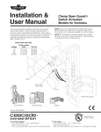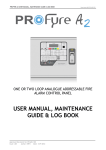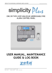
1
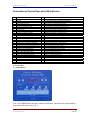
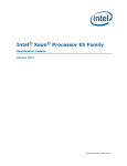
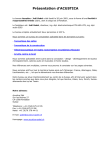
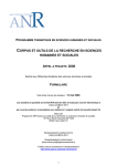
Premier Emergency Broadcast System
Stand Alone & Networked Systems
PEBS2000
Emergency Evacuation System
Operation Manual
GLT.MAN-123 Issue: 2
Date: 26/10/2009 Auth: NRPJ
1 of 23
Premier Emergency Broadcast System
Stand Alone & Networked Systems
INDEX
Caution................................................................................................................................ 3
INTRODUCTION. ............................................................................................................. 4
Basic Operation Description ............................................................................................... 4
PEBS CONTROLS & INDICATIONS .............................................................................. 5
Description of Control Keys and LED Indicators........................................................... 6
Mounting the PEBS system to a Wall................................................................................. 7
Installation and Commissioning ......................................................................................... 8
System Line Diagram ..................................................................................................... 8
Wiring a PEBS System ................................................................................................... 8
Connecting to mains. .................................................................................................. 8
Connecting the Speaker Circuits (Broadcast Area Output Terminals)....................... 9
Connecting the Remote Control Connections............................................................. 9
Connecting the Remote Microphone Input................................................................. 9
Connecting the Battery ............................................................................................. 10
CONFIGURING THE PEBS SYSTEM....................................................................... 11
Recording an Alert Message......................................................................................... 11
Recording an Evacuate Message. ................................................................................. 11
Changing the Alert tone ****NOT RECOMMENDED***** .................................... 11
Changing the EVACUATE tone ****NOT RECOMMENDED***** ....................... 12
Automatic operation of PEBS....................................................................................... 12
Message format............................................................................................................. 14
NETWORKED SYSTEMS .............................................................................................. 15
Using the Remote microphone operation button and indication light .......................... 16
Product Specifications ...................................................................................................... 17
(1) PEBS2000 Main Unit.............................................................................................. 17
(2) PEBS1000 Main Unit.............................................................................................. 18
(3) Broadcast Line Terminal Device (ESEOL) ............................................................ 19
(4) Remote Microphone (RMM2000) .......................................................................... 19
(5) 10 Way Master Microphone.................................................................................... 20
(6) Broadcast Speaker (CS3) ........................................................................................ 20
(7) Network data decode module (GXE0-2050-D) ...................................................... 21
(8) Remote control module PCB (GXE0-224E-C)....................................................... 21
(9) Remote microphone terminal .................................................................................. 22
12. Fault Analysis and Rectification................................................................................. 23
13. Storage Environment Requirements ........................................................................... 23
GLT.MAN-123 Issue: 2
Date: 26/10/2009 Auth: NRPJ
2 of 23
Premier Emergency Broadcast System
Stand Alone & Networked Systems
Caution
Thank you for choosing our Fire Emergency Broadcast System. Please be sure to read this
manual carefully before installation and use. Keep this manual nearby for reference whenever
necessary.
We reserve the right to make changes at any time without prior notice.
1. Be sure to familiarize yourself with this manual and perform all operations according to
instructions.
2. Use of 230V AC power supply. Ground the box well to ensure the personal safety of users.
3. Keep the main set from heat source, e.g. air conditioner or heater for proper ventilation and
cooling.
4. Scope of application Main set, broadcast line terminal device and speakers must be used in
matched set. Damage or other unexpected consequences will be caused as a result of improper
use.
5. Wait half an hour before powering up if the equipment is moved from outside into a room.
6. Avoiding from exposing main set to the sun. When the ambient temperature exceeds 50oC,
permanent damage will be caused.
7. Do not install the system in areas that are damp or humid, e.g. basement and other similar
places.
8. Maintenance
There are no user serviceable components in this unit. Trained personnel are required for
maintenance
GLT.MAN-123 Issue: 2
Date: 26/10/2009 Auth: NRPJ
3 of 23
Premier Emergency Broadcast System
Stand Alone & Networked Systems
INTRODUCTION.
The Premier Emergency Broadcast System (PEBS) is available in 2 versions:• The Original 4 channel unit with 300W total output – 75W/channel(PEBS 2000)
• And the 2 Channel unit with a total of 50W total output – 25W/channel (PEBS 1000)
These panels can be used in stand alone mode with a Standard Remote Microphone Unit
All panels made in 2009 or later have the option to be networked. To work in Network mode, each
panel has to be connected to a 10 way remote Microphone unit. There can be up to 10 units on
the network, with any combination of 2 channel or 4 channel units.
The total number of speakers that can be connected will depend on the model of PEBS, and also
the model of speaker. Zeta Alarm Systems supply speakers from 0.5W ceiling speakers to 10W
outside horn speakers.
The PEBS systems have 2 pre-recorded messages that can be triggered manually or
automatically. They also have a live broadcast microphone that can be used to broadcast
evacuation details.
Each channel needs an Emergency System End Of Line (ESEOL) unit fitted
The PEBS system has a built in speaker (for monitoring what is broadcast to the speaker lines).
The volume of this speaker is adjustable with the panel control buttons
This system is not suitable for use in hazardous areas.
Basic Operation Description
The PEBS system has been designed to provide the following functions:1.
2.
3.
Make a live broadcast using the inbuilt mic, or a remote microphone unit.
Play back a pre-recorded message (started manually at the unit)
Play back a pre-recorded message (started remotely via a fire alarm panel)
The Channels to be broadcast can be selected at the panel, or via the remote inputs.
If the remote channel select lines are not used, the channels should be selected by default.
Each PEBS control panel can only broadcast one message at a time, because the speaker lines
share a common amplifier.
GLT.MAN-123 Issue: 2
Date: 26/10/2009 Auth: NRPJ
4 of 23
Premier Emergency Broadcast System
Stand Alone & Networked Systems
PEBS CONTROLS & INDICATIONS
GLT.MAN-123 Issue: 2
Date: 26/10/2009 Auth: NRPJ
5 of 23
Premier Emergency Broadcast System
Stand Alone & Networked Systems
Description of Control Keys and LED Indicators
No
Name of Components
1
2
3
4
5
6
7
8
9
10
11
12
13
14
15
16
17
18
19
20
21
22
23
24
25
26
27
28
29
30
Reset Key
Test Key
Alert Message LED (Red)
Alert Message Play Key
Evacuation Message LED (Red)
Evacuation Message Play Key
Volume Down Key
Volume Up Key
Remote Mic Operation LED (Red)
Local Mic Operation LED (Red)
Microphone Open Circuit LED (Yellow)
Microphone Short Circuit LED (Yellow)
Broadcast Area 1 Operation LED (Red)
Broadcast Area 1 Open Circuit LED (Yellow)
Broadcast Area 1 Short Circuit LED (Yellow)
Broadcast Area 1 Start/Stop Key
Broadcast Area 2 Operation LED (Red)
Broadcast Area 2 Open Circuit LED (Yellow)
Broadcast Area 2 Short Circuit LED (Yellow)
Power Amplifier Overload LED (Yellow)
Broadcast Area 2 Start/Stop Key
Mains Operation LED (Green)
Mains Low Voltage LED (Yellow)
Standby Power Operation LED (Green)
Battery Low Voltage LED (Yellow)
Charging State LED (Green)
Battery Fault LED (Yellow)
Mains Switch
Direct Current Voltmeter
Standby Power Supply Switch
Function/Instruction
C
C
L
C
L
C
C
C
L
L
L
L
L
L
L
C
L
L
L
L
C
L
L
L
L
L
L
C
C
Stop playing alert or evacuation message
Test the operation state of indicators and speakers
Indicates alert message is playing
Starts playing pre-recorded alert message
Indicates evacuation message is playing
Starts playing pre-recorded evacuation message
Turn down internal speaker monitoring volume
Turn up internal speaker monitoring volume
Indicates the operation of remote microphone
Indicates the operation of local microphone
Open circuit of local or remote microphone (with microphone indicator)
Short circuit of remote microphone together with microphone indicator
Indicates broadcast area 1 output selected
Open circuit Fault on broadcast area 1
Short circuit Fault on broadcast area 1
Select / Cancel broadcast area 1 output
Indicates broadcast area 1 output selected
Open circuit Fault on broadcast area 2
Short circuit Fault on broadcast area 2
Critical loading or overload protection alarm of power amplifier
Select / Cancel broadcast area 2 output
Indicates Mains Power present
Mains Low voltage fault warning
Indicates Battery Power present
Battery Low voltage fault warning
Indicates normal battery charging
Open/short circuit fault warning of battery lead
Connects mains power to unit
Indicates voltage of power supply (D.C.)
Connects battery power to unit
C= Control Key
L = LED indicator
Note: The PEBS2000 has the same controls & Indicators, apart from the extra broadcast
area parts for the extra areas 3 & 4.
GLT.MAN-123 Issue: 2
Date: 26/10/2009 Auth: NRPJ
6 of 23
Premier Emergency Broadcast System
Stand Alone & Networked Systems
Mounting the PEBS system to a Wall
The PEBS Main units are quite heavy (20 kg for 2 channel PEBS1000, or 34 kg for 4 channel
PEBS2000). Take care to ensure that both the wall and the proposed fixing screws will be
suitable.
Mount the PEBS unit on firm wall with 4 steel bolts with cross-section at least 8mm.
Mount the remote microphone (RMM2000, or 10 way microphone) on firm wall with 4 steel bolts
with cross-section at least 6mm.
GLT.MAN-123 Issue: 2
Date: 26/10/2009 Auth: NRPJ
7 of 23
Premier Emergency Broadcast System
Stand Alone & Networked Systems
Installation and Commissioning
System Line Diagram
Wiring a PEBS System
Connecting to mains.
The mains power connection is located in the right top side of inside box. Please connect the
input line of AC power supply to the corresponding terminal according to following illustration.
After ensuring that the wires are fitted to the correct terminal, and are fitted tight, replace the
terminal protective cover. It is recommended that the mains connection is made with fire resistant
cable, such as our Fire Defense Cable, with a core cross section of at least 1.5 mm2.
GLT.MAN-123 Issue: 2
Date: 26/10/2009 Auth: NRPJ
8 of 23
Premier Emergency Broadcast System
Stand Alone & Networked Systems
Connecting the Speaker Circuits (Broadcast Area Output Terminals)
The broadcast area output terminal is located to the left side of the mains power terminal.
Please connect the wire of broadcast area that you need to the corresponding terminal according
to following illustration. To ensure the transmission distance of audio broadcast signal, we
suggest flame-retardant copper cord wire which cross-section is large than 1 mm2. Meanwhile,
keep distance away from equipments which have the capability of generating electromagnetic
interference.
Connecting the Remote Control Connections.
The remote control input terminal is located to the left side of broadcast area output terminal.
Please connect the remote control input wire to the corresponding terminal according to following
illustration.
It is recommended that the remote control connection is made with fire resistant cable, such as
out Fire Defense Cable, with a core cross section of at least 1.0 mm2.
It is recommended to keep distance away from equipment which has the capability of generating
strong electromagnetic interference.
There are controls for:• Select Channel 1
• Select Channel 2
• Select Channel 3
• Select Channel 4
• Select Alert Message
• Select Evacuate Message
Connecting the Remote Microphone Input.
The remote microphone input terminal is located to the left side of remote control input terminal.
Please connect the input wire of remote microphone that you need to the corresponding terminal
according to following illustration. To reduce the interference of ambient environment in audio
signal, use a 2 core screened cable. Connect the metal cover to the negative electrode of DC24V
power sauce, and keep distance away from equipments which have the capability of generating
strong electromagnetic interference.
GLT.MAN-123 Issue: 2
Date: 26/10/2009 Auth: NRPJ
9 of 23
Premier Emergency Broadcast System
Stand Alone & Networked Systems
1) Remote microphone input line
2) Remote microphone shielding line
3) Remote control COMMON line
4) Evacuation message remote play control line
5) Alert message remote play control line
6) Broadcast area 1 remote control line
7) Broadcast area 2 remote control line
8) Broadcast area 3 remote control line
9) Broadcast area 4 remote control line
10) Broadcast area 1 output line
11) Broadcast area 2 output line
12) Broadcast area 3 output line
13) Broadcast area 4 output line
14) Alternating current power supply line
15) Protective earth wire
Connecting the Battery
Fix the 2 charging batteries of 24AH, 12V on the bottom of the box with mounting rack provided.
Connect the 2 batteries in series with provided connecting wire (red). (Connect the Positive of
one battery to the negative of the other one). Connect the green wire marked “BAT+” to Empty
positive electrode of the linked batteries. Connect the black one marked “BAT-” to Empty negative
electrode, and screw all securing bolts tightly.
GLT.MAN-123 Issue: 2
Date: 26/10/2009 Auth: NRPJ
10 of 23
Premier Emergency Broadcast System
Stand Alone & Networked Systems
CONFIGURING THE PEBS SYSTEM
1. Connect all speakers, EOL units & remote microphone to the main panel
2. Turn on power
3. Press Test button. (panel will perform LED test)
4. Press & hold Test button for 3 seconds. The panel will now search for attached circuits &
configure them. The panel will beep & light the LED of a component it has configured
(Microphone or speaker circuit)
5. When the configuration is complete, press reset button
Recording an Alert Message.
1. Press test button
2. Press Alert button
3. Press button 2.
4. Pick up Mic & press speak button. Wait for panel to give confirmation beep before
speaking. Release button when message complete.
5. Press reset button to exit.
Recording an Evacuate Message.
1. Press test button
2. Press Evacuate button
3. Press button 2.
4. Pick up Mic & press speak button. Wait for panel to give confirmation beep before
speaking. Release button when message complete.
5. Press reset button to exit.
Changing the Alert tone ****NOT RECOMMENDED*****
1. Press test button
2. Press Alert button
GLT.MAN-123 Issue: 2
Date: 26/10/2009 Auth: NRPJ
11 of 23
Premier Emergency Broadcast System
Stand Alone & Networked Systems
3. Press button 1.
4. Pick up Mic & press speak button. Wait for panel to give confirmation beep before playing
new tone. Release button when complete.
5. Press reset button to exit.
Changing the EVACUATE tone ****NOT RECOMMENDED*****
1. Press test button
2. Press Evacuate button
3. Press button 1.
4. Pick up Mic & press speak button. Wait for panel to give confirmation beep before playing
new tone. Release button when complete.
5. Press reset button to exit.
Recording messages via the panel`s microphone does not always give the best results (because
of background noise etc)
It is possible to pre-load messages into the panels memory. Ask your distributor about this
service. There will be a small charge for this service.
Automatic operation of PEBS
There are 2 points to consider when the PEBS is to be automatically controlled by a fire alarm
panel:1. Type of connection.
The PEBs supports both a Relay (volt free) trigger and a “sounder circuit” (voltage) trigger.
GLT.MAN-123 Issue: 2
Date: 26/10/2009 Auth: NRPJ
12 of 23
Premier Emergency Broadcast System
Stand Alone & Networked Systems
If the shorting link XS9 is open, the trigger will be via Normally Open swich (or relay) contacts.
If the shorting link XS9 is closed, the trigger will be via a DC voltage signal (EG a sounder circuit).
The voltage trigger can be monitored by the Fire alarm panel, so can give a fault if the connection
is broken. However care must be taken if linking 2 or more control signals with different states,
that the different voltages do not cause a short circuit.
The relay trigger can not be monitored, because it is volt free. But as there is no voltage present,
it is possible to use all remote inputs without special precautions.
2. Required operation
Either:GLT.MAN-123 Issue: 2
Date: 26/10/2009 Auth: NRPJ
13 of 23
Premier Emergency Broadcast System
Stand Alone & Networked Systems
Leave all channels selected, and connect Fire panel alarm relay (Or I/O relay on addressable
system) to the Alert or Evacuate trigger.
OR
Connect Relays to channel select lines & Alert & Evacuate input
Program via fire alarm panel cause & effect which zones will operate, and whether they play alert
or evacuate message.
Message format
When a pre-recorded message is broadcast, the PEBS will initially play a siren tone for 3
seconds. It will then pause for 2 seconds. It will then play back the recorded message. After a
pause of 3 seconds it will repeat the cycle.
This will continue until the reset key is pressed, or the microphone is activated
GLT.MAN-123 Issue: 2
Date: 26/10/2009 Auth: NRPJ
14 of 23
Premier Emergency Broadcast System
Stand Alone & Networked Systems
NETWORKED SYSTEMS
Since early 2009, it has been possible to link together up to 10 PEBS panels via a 10 way master
microphone.
The Master Microphone connects to the remote microphone connector of each PEBS System.
Each PEBS panel will need a data decoder PCB fitted. This is usually fitted as the panels are final
tested.
The master microphone can now:1.
2.
Select lines to transmit a live message via the master microphone.
Using 24V triggering voltages, the master mic can command panels to:a. All play back their pre-recorded Alert Message
b. the selected unit will play back the pre-recorded EVACUATE message. All remaining 9
units will play back the pre-recorded alert message.
c. All play back their pre-recorded EVACUATE Message
GLT.MAN-123 Issue: 2
Date: 26/10/2009 Auth: NRPJ
15 of 23
Premier Emergency Broadcast System
Stand Alone & Networked Systems
Using the Remote microphone operation button and indication
light
No.
1
2
3
4
5
6
7
8
9
10
11
12
13
14
15
16
17
18
19
20
21
22
23
Part name
PEBS #1 connecting key
PEBS #2 connecting key
PEBS #3 connecting key
PEBS #4 connecting key
PEBS #5 connecting key
PEBS #6 connecting key
PEBS #7 connecting key
PEBS #8 connecting key
PEBS #9 connecting key
PEBS #10 connecting key
All main set connecting key
PEBS #1 Active LED
PEBS #2 Active LED
PEBS #3 Active LED
PEBS #4 Active LED
PEBS #5 Active LED
PEBS #6 Active LED
PEBS #7 Active LED
PEBS #8 Active LED
PEBS #9 Active LED
PEBS #10 Active LED
Mains power on LED (green)
Back up power on LED (green)
Function
Select No.1 main set, related light working
Select No.2 main set, related light working
Select No.3 main set, related light working
Select No.4 main set, related light working
Select No.5 main set, related light working
Select No.6 main set, related light working
Select No.7 main set, related light working
Select No.8 main set, related light working
Select No.9 main set, related light working
Select No.10 main set, related light working
Select all main set, related light working
No.1 main set connecting selection indication
No.2 main set connecting selection indication
No.3 main set connecting selection indication
No.4 main set connecting selection indication
No.5 main set connecting selection indication
No.6 main set connecting selection indication
No.7 main set connecting selection indication
No.8 main set connecting selection indication
No.9 main set connecting selection indication
No.10 main set connecting selection indication
AC power supply working indication
Storage battery working indication
24
Battery Fault (yellow)
Storage battery low voltage indication
25
26
Main power supply switch
Back up power supply switch
Control the AC input
Control the Storage battery input
Press the relevant PEBS SYSTEM select button so select which PEBS panels to broadcast to.
(EG press 1,3 & 7 to use the microphone to broadcast on panels 1,3 &7). Press the microphone
to begin broadcast. To deselect a system, press that system’s number again.
Press ALL to select to broadcast to all systems connected.
GLT.MAN-123 Issue: 2
Date: 26/10/2009 Auth: NRPJ
16 of 23
Premier Emergency Broadcast System
Stand Alone & Networked Systems
Product Specifications
(1) PEBS2000 Main Unit
Item
Parameter
Input Sensitivity of Local Microphone
1mv
Input Sensitivity of Remote Microphone
300 mv
Signal-to Noise Ratio
≥55dB
Rated Output Power
Voltage Regulation
Frequency Characteristics
Harmonic Distortion
Output Characteristics
Total Number of Broadcast Areas
Message Storage Time
Monitoring Output Power
300W
≤2dB
63Hz-10kHz ≤1dB
≤5%
120V (Constant Voltage)
4-channel
2 minutes
≥0.25W
Operation Range of Mains
AC195V~253V 50 60Hz
Low Voltage Alert Point of Mains
AC176V~187V
Range of Mains Low Voltage Protection
Operation Range of Standby Power
Supply
Low Voltage Alert Point of Standby Power
Supply
Range of Standby Power Supply
Low Voltage Protection
AC170V
DC20V 28V
DC 21.5V±1V
-1.6V (low voltage alert point of standby power supply)
Charging Range of Standby Power Supply
DC 18V
Dimension: 530mm×230mm× 720mm (L×W×H)
Net Weight: 34Kg
GLT.MAN-123 Issue: 2
Date: 26/10/2009 Auth: NRPJ
17 of 23
Premier Emergency Broadcast System
Stand Alone & Networked Systems
(2) PEBS1000 Main Unit
Item
Input Sensitivity of Local Microphone
Input Sensitivity of Remote Microphone
Signal-to Noise Ratio
Rated Output Power
Voltage Regulation
Frequency Characteristics
Harmonic Distortion
Output Characteristics
Total Number of Broadcast Areas
Message Storage Time
Monitoring Output Power
Operation Range of Mains
Low Voltage Alert Point of Mains
Range of Mains Low Voltage Protection
Operation Range of Standby Power Supply
Low Voltage Alert Point of Standby Power
Range of Standby Power Supply Low Voltage Protection
Charging Range of Standby Power Supply
Parameter
1mV
300 mV
≥55dB
300W
≤2dB
63Hz~10kHz ≤1dB
≤5%
120V (Constant Voltage)
2-channel
2 minutes
≥0.25W
AC195V~253V 50/60Hz
AC176V~187V
<AC170V
DC20V~28V
DC 21.5V±1V
-1.6V
>DC 18V
Dimension: 460mm×210mm× 5500mm (L×W×H)
Net Weight: 20Kg
BOTH UNITS:-
Operating Environment
Temperature: 0℃~40℃
Moisture: ≤90%RH
Air Pressure: 86~106kPa
GLT.MAN-123 Issue: 2
Date: 26/10/2009 Auth: NRPJ
18 of 23
Premier Emergency Broadcast System
Stand Alone & Networked Systems
(3) Broadcast Line Terminal Device (ESEOL)
Item
Range of Operation Voltage
Maximum Power Consumption
Parameter
120V (Constant Voltage)
120mW
Dimension: 103mm×66mm×27mm (L×W×H)
Net Weight: 0.1Kg
(4) Remote Microphone (RMM2000)
Item
Range of Operation Voltage
Maximum Power Consumption
Input Sensitivity of Microphone
Signal Gain
Frequency Characteristics
Longest Distance of Wiring
Parameter
DC20V-28V
120mw
1mv
50dB
300Hz-3400Hz
1000 meters
GLT.MAN-123 Issue: 2
Date: 26/10/2009 Auth: NRPJ
19 of 23
Premier Emergency Broadcast System
Stand Alone & Networked Systems
(5) 10 Way Master Microphone
Item
Range of Operation Voltage
Maximum Power Consumption
Input Sensitivity of Microphone
Signal Gain
Frequency Characteristics
Longest Distance of Wiring
Parameter
DC20V~28V
120mw
1mv
>50Db
300Hz~3400Hz
1000 meters
Dimension: 330mm×390mm×120mm (L×W×H)
Net Weight: 7.3Kg
(6) Broadcast Speaker (CS3)
Item
Input Audio Voltage
Rated Input Power
Frequency Response
Sensitivity
Parameter
120V (Constant Voltage)
3W
120Hz~11kHz
90dB±3dB
Dimension: Diameter × Height ¢230mm×125mm
Net Weight: 1.3Kg
GLT.MAN-123 Issue: 2
Date: 26/10/2009 Auth: NRPJ
20 of 23
Premier Emergency Broadcast System
Stand Alone & Networked Systems
(7) Network data decode module (GXE0-2050-D)
When using this module, please use 10 WAY RIBBON CABLE to connect XS2 and the XS2 of
E0-2050B (2 channel) or E0-2300B (4 channel) circuit boards
(8) Remote control module PCB (GXE0-224E-C)
This PCB is part of the 10 way master microphone.
No.
1
3
5
7
9
11
13
15
17
19
21
23
25
Description
EVAC +
EVAC 1 +
EVAC 2+
EVAC 3+
EVAC 4+
EVAC 5+
EVAC 6+
EVAC 7+
EVAC 8+
EVAC 9+
EVAC 10+
ALERT +
CONNECTOR TO 224EB CIRCUIT BOARD
No.
2
4
6
8
10
12
14
16
18
20
22
24
Description
EVAC EVAC 1EVAC 2EVAC 3EVAC 4EVAC 5EVAC 6EVAC 7EVAC 8EVAC 9EVAC 10ALERT -
GLT.MAN-123 Issue: 2
Date: 26/10/2009 Auth: NRPJ
21 of 23
Premier Emergency Broadcast System
Stand Alone & Networked Systems
The Remote Control Module works as follows:If you apply 15~30VDC to Alert Terminals, all 10 PEBS systems connected will play alert
message.
If you apply 15~30VDC to Evac Terminals, all 10 PEBS systems connected will play evac
message.
If you apply 15~30VDC to Evac1 Terminals, PEBS 1 will play Evac message, all other PEBS will
play alert message.
If you apply 15~30VDC to Evac2 Terminals, PEBS 2 will play Evac message, all other PEBS will
play alert message.
ETC
If you apply 15~30VDC to Evac1 AND Evac2 Terminals, PEBS 1 & 2 will play Evac message, all
other PEBS will play alert message.
(9) Remote microphone terminal
No.
1
3
5
7
9
11
13
15
17
19
Description
LIN1A
LIN2A
LIN3A
LIN4A
LIN5A
LIN6A
LIN7A
LIN8A
LIN9A
LIN10A
Connect to
PEBS 1 remote mic connection A
PEBS 2 remote mic connection A
PEBS 3 remote mic connection A
PEBS 4 remote mic connection A
PEBS 5 remote mic connection A
PEBS 6 remote mic connection A
PEBS 7 remote mic connection A
PEBS 8 remote mic connection A
PEBS 9 remote mic connection A
PEBS 10 remote mic connection A
No.
2
4
6
8
10
12
14
16
18
20
Description
LIN1B
LIN2B
LIN3B
LIN4B
LIN5B
LIN6B
LIN7B
LIN8B
LIN9B
LIN10B
Connect to
PEBS 1 remote mic connection B
PEBS 2 remote mic connection B
PEBS 3 remote mic connection B
PEBS 4 remote mic connection B
PEBS 5 remote mic connection B
PEBS 6 remote mic connection B
PEBS 7 remote mic connection B
PEBS 8 remote mic connection B
PEBS 9 remote mic connection B
PEBS 10 remote mic connection B
Terminals LINnA and LINnB connect to the Remote Mic Input of PEBS panel No. “n” (n=1~10)
GLT.MAN-123 Issue: 2
Date: 26/10/2009 Auth: NRPJ
22 of 23
Premier Emergency Broadcast System
Stand Alone & Networked Systems
12. Fault Analysis and Rectification
In the event of a fault condition, the PEBS will light the appropriate fault LED & play a fault tone
on it`s internal speaker. Press any key except monitoring volume key to cancel fault alarm sound.
The fault indicator LEDs will stay on until the fault has been rectified.
Symptom
Analysis
Remedy
Indicator does not light
Is there AC230V input
voltage?
Is the switch of mains on?
Check the safety Fuse
Check the connection of
electrode of DC24V power
supply (batteries)
There is overloading of power
amplifier.
There is serious circuit fault.
Link the power supply.
Overload indicator lights
Microphone does not work
properly
Broadcast area can not put
through
Mains low voltage indicator
lights
Standby power supply low
voltage lights
Standby power supply fault
indicator lights
Turn on the switch
Change safety Fuse
Reconnect
Decrease the number of
speakers and alarms.
Check and remove the circuit
fault
Configure the system
Has the system been
configured?
Are the wires in good
condition?
Has the system been
configured?
Are the wires in good
condition?
Is the end of line connected &
working?
The AC input voltage is too
low.
The battery voltage is too low.
Charge the battery.
Open circuit or short circuit of
the connection of battery.
Check and remove the circuit
fault.
Check and remove the fault.
Configure the system
Check and remove the fault.
Fit or replace EOL as
necessary
Increase the AC input voltage.
13. Storage Environment Requirements
Temperature: -10~55oC
Relative Humidity: 15%~90%
Air Pressure: 86~106kPa
Storage Duration: 2 years
Please energize power supply at least 4 hours to continue storage when the equipment has been
stored for more than 1 year.
GLT.MAN-123 Issue: 2
Date: 26/10/2009 Auth: NRPJ
23 of 23