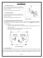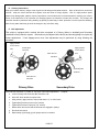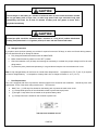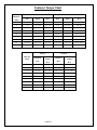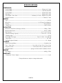
1
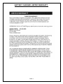
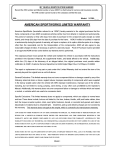
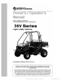
OWNER’S/OPERATOR’S MANUAL – 36V SERIES PART NUMBER 15293 TABLE OF CONTENTS TABLE OF CONTENTS..................................................................................................................................... 1 MY VEHICLE IDENTIFICATION NUMBER ............................................................................................. 3 AMERICAN SPORTWORKS LIMITED WARRANTY .............................................................. 3 BATTERY CHARGER LIMITED WARRANTY ......................................................................... 4 BATTERY LIMITED WARRANTY ............................................................................................. 5 WARNINGS AND CAUTIONS .................................................................................................... 8 SOME WORDS ABOUT SAFETY............................................................................................. 17 SAFETY LABELS ...................................................................................................................... 17 QUALIFICATIONS FOR USERS............................................................................................... 19 VEHICLE CONTROLS AND OPERATION .............................................................................. 21 Controls and Features .......................................................................................................... 21 A. Throttle................................................................................................................................. 21 B. Brake .................................................................................................................................... 22 C. Parking Brake....................................................................................................................... 22 D. Lights ................................................................................................................................... 22 E. Power Outlet ........................................................................................................................ 22 F. Keyed Ignition Switch ......................................................................................................... 22 G. Rear View Mirror ................................................................................................................. 22 H. Seat Adjustment ................................................................................................................... 22 I. Occupant Restraints ............................................................................................................. 22 J. Under-seat Storage ............................................................................................................... 23 K. Forward / Reverse Switch .................................................................................................... 23 L. Tool Holders......................................................................................................................... 24 M. Cargo Dump Bed – 250lb MAX LOAD........................................................................... 25 N. Charge Gauge....................................................................................................................... 25 O. TAILGATE LATCH AND REMOVAL ............................................................................... 25 P. BASIC RADIO OPERATION ............................................................................................. 25 VEHICLE FEATURES AND LOCATIONS ............................................................................... 27 ARE YOU READY TO DRIVE? ................................................................................................ 28 Protective Apparel ................................................................................................................ 28 Helmet and Eye Protection .................................................................................................. 28 Additional Driving Gear ...................................................................................................... 28 PAGE 1 OWNER’S/OPERATOR’S MANUAL – 200 SERIES PART NUMBER 15293 Driver Training..................................................................................................................... 28 No Alcohol or Drugs ............................................................................................................ 29 IS YOUR VEHICLE READY TO DRIVE? ................................................................................ 30 Battery Charging .................................................................................................................. 30 Pre-Ride Inspection .............................................................................................................. 31 Starting Instructions ............................................................................................................. 33 OPERATION - SAFE DRIVING PRECAUTIONS .................................................................... 33 UNIT SERVICE ........................................................................................................................... 36 A. Front Wheel Replacement .................................................................................................... 36 A. Rear Wheel Replacement ..................................................................................................... 36 B. Front Wheel Alignment (Ref Toe Adjustment Diagram) ..................................................... 36 C. General Lubrication ............................................................................................................. 36 D. Cleaning Instructions ........................................................................................................... 37 E. Belt Adjustment ................................................................................................................... 37 F. Adjustment of Front and Rear Shock ................................................................................... 38 G. Battery Watering .................................................................................................................. 38 H. Storage Instruction ............................................................................................................... 40 I. Fuse Replacement ................................................................................................................ 40 Fastener Torque Chart .................................................................................................................. 41 ACCESSORIES ........................................................................................................................... 42 REPLACEMENT PARTS AND SERVICE ................................................................................. 42 SPECIFICATIONS ...................................................................................................................... 43 ELECTRICAL SCHEMATICS ................................................................................................... 45 PAGE 2 OWNER’S/OPERATOR’S MANUAL – 200 SERIES PART NUMBER 15293 MY VEHICLE IDENTIFICATION NUMBER Record the VIN number and Model number of your American SportWorks vehicle below for service and insurance records. The VIN number is hard tagged on the vehicle frame under the bed. VIN: L6KUA00__ __ __ __ __ __ __ __ __ __ Model: __ __36 AMERICAN SPORTWORKS LIMITED WARRANTY American SportWorks (hereinafter referred to as “ASW”), hereby warrants to the original purchaser, that the frame components of new ASW vehicles will be free from defects in material and workmanship. The period of warranty is (1) year from date of purchase for the component parts (except as noted below), and (1) year from the date of purchase for the frame. ASW, if notified of a defect in material or workmanship during the period of warranty, will repair or replace, at its option, defective parts at no charge, other than the reasonable cost for the transportation of the component(s). will also agree to pay reasonable charges for labor, if necessary, to perform a warranty repair. ASW Proof of Purchase must be provided to an approved ASW service center before any warranty work is performed. The original purchaser must operate the vehicle and maintain the vehicle in accordance with the instructions provided in the Operator’s Manual, the supplements hereto, and labels affixed to the vehicle. Additionally, within (10) days of the discovery of an alleged defect, the original purchaser must contact ASW’s Customer Service Department at 1-800-643-7332, 4404 Engle Ridge Drive, Fort Wayne, IN 46804 or via the internet at www.amsportworks.com. The repair or replacement of any part or parts under this Limited Warranty shall not extend the term of the warranty beyond the original term as set forth above. General Exclusions: This limited warranty does not cover component failure or damage caused by any of the following: abnormal strain or stress, neglect; abuse; improper assembly of components which were supplied in the factory sealed carton after the vehicle left ASW; improper maintenance, improper use of the vehicle, including, but not limited to racing, jumping, stunt driving, overloading, or any other uses prohibited by the Operator’s Manual. Additionally, this warranty does not cover component failure or damage to vehicles which are leased, rented, or used at a concession track. Specific Exclusions: This limited warranty does not apply to components, which are subject to normal wear and tear and natural discoloration of material due to ultraviolet light. These items include, but are not limited to, the tires, brakes, throttle, shift and brake cables, drive belt, seat, lights, fasteners, decals, or cosmetic body panels. Downtime, pick-up and delivery charges are not covered by this warranty. ASW MAKES NO OTHER WARRANTY OF ANY KIND, EXPRESSED OR IMPLIED. ALL WARRANTIES OF MERCHANTABILITY AND FITNESS FOR A PARTICULAR PURPOSE WHICH EXCEED THE OBLIGATIONS AND TIME LIMITATIONS SPECIFIED IN THE WARRANTY ABOVE ARE HEREBY DISCLAIMED BY ASW AND EXCLUDED FROM THIS WARRANTY. ADDITIONALLY, THIS WARRANTY EXCLUDES ANY INCIDENTAL OR CONSEQUENTIAL DAMAGES, INCLUDING BUT NOT LIMITED TO LOSS OF USE. SOME STATES DO NOT ALLOW A MANUFACTURER TO EXCLUDE OR LIMIT INCIDENTAL OR CONSEQUENTIAL DAMAGES AND, THEREFORE, THE ABOVE EXCLUSION MAY NOT APPLY TO YOU. SOME STATES DO NOT ALLOW LIMITATIONS ON HOW LONG AN IMPLIED WARRANTY WILL LAST, IT IS POSSIBLE THAT THE ABOVE LIMITATION MAY NOT APPLY TO YOU. THIS WARRANTY GIVES YOU SPECIFIC LEGAL RIGHTS, AND YOU MAY ALSO HAVE OTHER LEGAL RIGHTS, WHICH VARY, FROM STATE TO STATE. PAGE 3 OWNER’S/OPERATOR’S MANUAL – 200 SERIES PART NUMBER 15293 BATTERY CHARGER LIMITED WARRANTY PAGE 4 OWNER’S/OPERATOR’S MANUAL – 200 SERIES PART NUMBER 15293 BATTERY LIMITED WARRANTY PAGE 5 OWNER’S/OPERATOR’S MANUAL – 200 SERIES PART NUMBER 15293 RESPONSIBLE BATTERY SAFETY AND DISPOSAL Lead-acid batteries are completely recyclable. Return whole scrap battery to distributor, manufacturer or lead smelter for recycling. For neutralized spills, place residue in acid-resistant containers with sorbent material, sand or earth and dispose of in accordance with local, state and federal regulations for acid and lead compounds. Contact local and/or state environmental officials regarding disposal information. PAGE 6 OWNER’S/OPERATOR’S MANUAL – 200 SERIES PART NUMBER 15293 PAGE 7 OWNER’S/OPERATOR’S MANUAL – 200 SERIES PART NUMBER 15293 FOREWORD Congratulations on the purchase of your ASW Vehicle. Before operating this vehicle, the owner and each operator must understand that, unless specifically equipped and labeled as a street legal Low Speed Vehicle (LSV), this vehicle was not designed or manufactured to meet specifications for use on public roads, streets, highways and thoroughfares The owner, operator(s) and passenger(s) must read and understand all the instructions for proper assembly and safe operation, as well as the instructions concerning the engine and all other portions of the vehicle as described and illustrated in this manual and on the included safety DVD. This unit is not designed for children, and is not a toy. Be sure to follow the recommended maintenance schedule and service your vehicle accordingly. Preventative maintenance is extremely important to the longevity of your vehicle. First time drivers are urged to seek instruction from a dealer or qualified instructor before and during the initial use of this unit. It is also recommended to practice in a large open area to become familiar with the operation of the vehicle. We hope you will have a fun, safe experience with our products and thank you again for choosing an American Sportworks Vehicle. WARNINGS AND CAUTIONS This is the safety alert symbol. When you see this symbol on your machine or in this manual, be alert to the potential for personal injury. Read and follow all instructions in this Owner’s/Operator’s manual and any accompanying supplements before attempting to operate this vehicle. Make sure to view the Operations and Safety DVD. WARNING Never operate this vehicle when the seat is not securely locked into position. death could occur due to loss of control. Serious injury or Always make seat adjustments with the vehicle fully stopped and the engine shut off. CAUTION Indicates a potential hazard which may result in personal injury or damage to the machine. NOTE: Use of the word “NOTE” will alert you to key information or instructions. PAGE 8 OWNER’S/OPERATOR’S MANUAL – 200 SERIES PART NUMBER 15293 IMPORTANT SAFETY INFORMATION WARNING Hydrogen gas is generated as a natural part of the lead acid battery charging process. concentration of hydrogen gas is explosive and could cause severe injury or death. A 4% Charging must take place in an area that is adequately ventilated (minimum of 5 air exchanges per hour). To reduce the chance of battery explosion that could result in severe injury or death, never smoke around batteries or charge them in an area that has open flame or electric equipment that could cause an electric arc. CAUTION Overfilling batteries may result in electrolyte being expelled from the battery during the charge cycle. Expelled electrolyte may cause damage to the vehicle and storage facility. WARNING Always wear a safety shield or approved safety glasses when adding water or charging batteries. CAUTION Electrolyte spills should be neutralized with a solution of ¼ cup (60 ml) sodium bicarbonate (baking soda) dissolved in 1-1/2 gallons (6 liters) of water and then flushed with water. WARNING Do NOT place metal objects, or let them fall, onto the top of the batteries as this may cause an electrical short and the possibility of a fire. PAGE 9 OWNER’S/OPERATOR’S MANUAL – 200 SERIES PART NUMBER 15293 CAUTION The electrolyte in the battery is a solution of acid and water so skin contact should be avoided. Do not get battery acid on eyes, face, or other body parts. Flush eyes and other body parts immediately with water for at least 15 minutes if battery acid has gotten on them. Call a physician immediately. WARNING This vehicle may have been supplied to you completely assembled. To prevent injury or death read and follow the assembly instructions to make sure the unit was assembled properly. WARNING NEVER adjust, repair, or clean the machine while it is in motion. WARNING Check tire pressure before each use. - Prior to operating the vehicle check and adjust tire pressure to the proper operating pressure as indicated on the sidewall of each tire or in the specification section of this manual. A tire pressure gauge is required to obtain accurate readings. WARNING Vehicle modification or removal of original equipment or safety decals can render the machine unsafe for operation. PAGE 10 OWNER’S/OPERATOR’S MANUAL – 200 SERIES PART NUMBER 15293 WARNING Safety decals must be replaced if they become unreadable or detached from the vehicle. - If decals are unreadable or missing, warning of potential hazards or safety requirements may be lacking. WARNING The safe operation of this vehicle is dependent upon the operator’s ability to exercise proper judgment. - Operator and passenger must not be too small or too large for controlled operation. - Operator and passenger must be of sufficient age, understanding, mental capacity, and physical capacity to safely operate the vehicle. - Vehicle should only be operated after mature, supervised instruction and sufficient practice in an un-congested area. WARNING It is strongly recommended that Operator and any passengers wear a properly fitting motorcycle helmet approved by agencies such as the Department of Transportation (DOT), Safety Helmet Council of America (SHCA), or Snell Memorial Foundation (SNELL). - Most accident fatalities are due to head injuries. - Operator (and any passenger) should also wear face shields or goggles, boots, gloves and other appropriate protective clothing. (See MACHINE OPERATION) WARNING Long hair, loose clothes, or jewelry can get caught in moving parts below and behind the seat or surrounding environment. - Remove or tie back anything loose that can reach below and behind the seat before riding. PAGE 11 OWNER’S/OPERATOR’S MANUAL – 200 SERIES PART NUMBER 15293 WARNING NEVER place hands, feet, or any body parts or clothing near the motor, wheels, belts, and other rotating parts of the vehicle while riding. - Use caution in performing required maintenance on or near operating motor. - Use caution after the motor has been running, since the motor and other drive components may be extremely hot. WARNING STOP the motor and vehicle if you experience unusual noises or vibrations. - Check the vehicle for damage. - Excessive noise or vibration is a sign of loose or worn parts. WARNING Keep guards in place at all times. - Prevent accidental contact by the operator or service personnel while the vehicle is running. - The guards over the brake, motor, axle and drive pulleys also help prevent mud and debris from coming in contact with those items. WARNING Be sure the passenger restraint system (i.e. Seat Belt) is properly adjusted and fastened at all times during operation. - If the passenger restraint system is not properly used by the operator and/or passengers, loss of control and possible personal injury and/or vehicle damage can occur. PAGE 12 OWNER’S/OPERATOR’S MANUAL – 200 SERIES PART NUMBER 15293 WARNING When there is no passenger in the vehicle, the passenger seatbelt must be securely fastened within the vehicle. - If the passenger restraint system is not properly used by the operator and/or passenger, loss of control and possible personal injury and/or vehicle damage can occur. WARNING All screws, nuts, and bolts must be properly tightened to make sure the vehicle is in safe operating condition. WARNING Prevailing-torque type locknuts must be replaced with new after the old locknuts have been removed. - Replace with the same type of locknut to make sure they function properly. Refer to the maintenance section for more information on locknuts. WARNING Keep the motor free of dirt and debris, especially in the drive belt area. WARNING NEVER operate the vehicle without the operator and passengers properly seated and the restraint system properly adjusted and secured. PAGE 13 OWNER’S/OPERATOR’S MANUAL – 200 SERIES PART NUMBER 15293 WARNING NEVER power on the unit unless the throttle control is in its initial, fully returned, position. WARNING NEVER tamper with, alter, or change the vehicle motor governor settings. The governor as set by the motor manufacturer, limits maximum engine speed and protects - the motor from damage. Excessive motor speed is potentially dangerous to operator, passengers, bystanders, and - engine. WARNING Wet, slippery, rough, or sloped terrain is potentially dangerous and may result in injury if proper caution is not observed. - ALWAYS SLOW DOWN - Operator must use mature judgment, skill, and experience to choose a speed suitable for terrain and riding conditions in protecting operator and any bystanders. Operator must use mature judgment, skill and experience in choosing suitable terrain for - individual operational capabilities. WARNING When turning on pavement, loose gravel, or similar surfaces, there is an increased risk in loss of control. ** ALWAYS SLOW DOWN! ** WARNING ALWAYS SLOW DOWN when turning. - High-speed turning can cause loss of control and/or possible operator injury. - Turning on a slope increases the risk of rollover. - Practice operation is required to coordinate turning skill. - Failure to operate this vehicle at a safe speed while turning can result in a strong possibility of severe personal injury. PAGE 14 OWNER’S/OPERATOR’S MANUAL – 200 SERIES PART NUMBER 15293 WARNING Do NOT place metal objects, or let them fall, onto the top of the batteries as this may cause an electrical short and the possibility of a fire. WARNING Operating the vehicle in conditions where water, mud, snow, dirt, sand, or other debris can get into the throttle mechanism can prevent throttle return. - This may result in the motor continuing to run and result in loss of control. WARNING Assembly, maintenance, and/or repair of this vehicle should only be performed by designated dealers or authorized small engine centers (for engine repairs) so that no unsafe conditions or modifications are made. WARNING Read and keep all supplied printed material. - Supplements to this Operator’s Manual contain updated information relative to your specific vehicle model. It is important to keep all of these documents for reference. CAUTION During vehicle storage and/or charging, keep it in a place where hydrogen fumes from the battery will not reach an open flame, spark, or other source of ignition. - For long term storage: Fully charge battery and then disconnect the MAIN FUSE. PAGE 15 OWNER’S/OPERATOR’S MANUAL – 200 SERIES PART NUMBER 15293 WARNING When making repairs or adjustments to the vehicle, the batteries MUST be disconnected to prevent accidental starting. WARNING When working on or around, the vehicle, use extreme caution to avoid contact with any potentially hot area, such as the motor and motor controller. WARNING NEVER operate the vehicle while under the influence of alcohol, drugs, or medication of any kind. - Such operation is dangerous to yourself and/or others. CAUTION Brush Bars assembled to this vehicle are for decorative purpose and limited brush protection. - Brush Bars were not designed for roll over or to restrict all brush or tree branches from protruding into operator/passenger compartment. CAUTION If the vehicle should start making unusual noise or vibrating abnormally, the vehicle should be stopped and the batteries disconnected. The vehicle should then be checked for damage. Excessive noise or vibration is generally a warning of loose or worn parts. PAGE 16 OWNER’S/OPERATOR’S MANUAL – 200 SERIES PART NUMBER 15293 SOME WORDS ABOUT SAFETY The following pages present important information and recommendations to help you drive your vehicle safely. Please read through these pages thoroughly and view the Safety DVD that was included with your unit. SAFETY LABELS The following labels have been applied to your unit and should be considered as permanent parts of the vehicle. If a label should come off, become hard to read, or become damaged, contact your dealer or American SportWorks Customer Service department for warning label replacements. PAGE 17 OWNER’S/OPERATOR’S MANUAL – 200 SERIES PART NUMBER 15293 PAGE 18 OWNER’S/OPERATOR’S MANUAL – 200 SERIES PART NUMBER 15293 QUALIFICATIONS FOR USERS This vehicle is recommended for use by operator and passenger with a minimum age of sixteen years. Vehicles are intended for use by operators who meet the physical and cognitive capabilities set out by the manufacturer in the material provided with the vehicle. Consumer Responsibility for Safe Use and Maintenance of a Vehicle Note: For the purpose of the following, if not specified, an engine is defined as gasoline powered and motor is defined as an electrical device. 1. Vehicle shall not be modified from the manufacturer’s original design and configuration. 2. Vehicle shall not be used to perform racing, stunt riding, jumps, spinouts, donuts, or other maneuvers as they may cause loss of control. As such, these activities are likely to result in possible injury to the operator, bystanders, or both. 3. Prior to each use, the operator shall perform the preoperational checks specified by the manufacturer, and further verify: a. Smooth throttle operation and positive return of the pedal and additionally for gas engines, of the throttle linkage, to a closed throttle position when released; b. That the throttle cable and linkages operate properly and the throttle cable or other linkages be adjusted properly for gas engines; c. That the steering linkage is adjusted and operates smoothly; d. That the engine stop switch is properly functioning for gas powered models or the keyed ignition switch is functioning properly for electric models; e. That all guards originally supplied by the manufacturer are in proper place in serviceable condition; f. That engine idle speed is below the point of clutch or torque converter engagement for gas models; g. That the gas tank is in good condition and the proper gas cap is fastened securely for gas models; h. That the braking system is functioning properly; i. That all safety labels are in place, legible and understood; j. That any and all axle guards as applicable to the model, such as chain guards, belt guards, torque converter covers, or other covers or guards, supplied by the manufacturer are in place and in serviceable condition; k. That tires are in good condition, inflated properly, and have sufficient tread remaining; and l. That all fasteners are in place and tightened securely. 4. Vehicle engines shall not be started, or motors powered on, unless the operator is seated in proper position for vehicle operations and the brake fully engaged. 5. Long hair, loose clothes, or jewelry can get caught in moving parts below the seat or surrounding environment. Remove or tie back anything loose that can reach below or behind the seat before riding. 6. Vehicles shall only be fueled or charged by an operator knowledgeable with regard to proper fueling and charging techniques. 7. All operators or riders shall be knowledgeable, capable, and have the cognitive capacity to operate the vehicle safely, including those items specified in 1 through 6. 8. Vehicle operators and passengers shall adhere to all manufacturer’s recommendations and instructions, as well as comply with all laws and ordinances, as well as: PAGE 19 OWNER’S/OPERATOR’S MANUAL – 200 SERIES PART NUMBER 15293 a. Operators shall stay seated with both hands on the steering wheel and both feet in the vehicle at all times, whether moving or stationary, unless the vehicle is stopped completely and the engine has been shut off or the motor powered down. b. Passengers shall remain seated with arms and legs inside the vehicle at all times during vehicle operation. c. Shall observe minimum age restrictions. d. Shall not ride the vehicle if long hair, loose clothes, or jewelry reach below or behind the seat. WARNING Long hair, loose clothes, or jewelry can get caught in moving parts below and behind the seat or surrounding environment. Remove or tie back anything loose that can reach below and behind the seat before riding. e. Shall not allow smoking in vehicle. f. Persons under the influence of drugs, alcohol, or intoxicants shall not supervise, operate, or ride in a vehicle. g. Vehicles shall operate only on a surface or terrain recommended by the vehicle’s manufacturer. h. Vehicles shall not be operated on roads, streets, highways, or any other location where road vehicles are intended to travel unless specifically designed and designated for such use. i. Vehicles shall be operated only with adequate lighting and under conditions of suitable visibility. 9. Persons with the following conditions shall not ride in or operate a Vehicle: a. Those with heart conditions b. Pregnant women c. Persons with head, back, or neck ailments, or prior surgeries to those areas of the body. d. Persons with any mental or physical conditions, which may make them susceptible to injury or impair their physical dexterity or mental capabilities to recognize, understand, and perform all of the safety instructions, and be able to assume the hazards inherent in vehicle use. 10. Vehicle shall not be used to: a. Transport a passenger, or passengers, except in the seating area(s) provided. b. Transport materials or equipment in excess of the rated cargo capacity; 11. Vehicle operators always shall use appropriate protective clothing, including but not limited to a motorcycle type helmet and eye protection, with appropriate certification, and any other equipment recommended by the vehicle manufacturer including gloves, footwear, long sleeve shirts, and long pants. 12. No operator or other person shall contact any portion of the engine, wheels, or drive train for any purpose including maintenance until the engine or motor has been turned off and allowed to cool, and the vehicle is in a stable and stationary position. 13. Passenger restraints must be used in accordance with, and limited to, the manufacturer’s guidelines. 14. Vehicle components shall be maintained and repaired in accordance with the manufacturer’s specifications and utilizing only the manufacturer’s authorized replacement parts with installation performed by designated dealers or other skilled persons. PAGE 20 OWNER’S/OPERATOR’S MANUAL – 200 SERIES PART NUMBER 15293 VEHICLE CONTROLS AND OPERATION Controls and Features WARNING Do not attempt to start or operate the vehicle until completely familiar with the location and use of each control necessary to operate this vehicle. The operator must know how to stop this machine before starting and driving it. SWITCH – CARGO LIGHT SWITCH – HEAD LIGHT CUP HOLDER BATTERY KEYED IGNITION STEERING WHEEL METER 12V POWER OUTLET PARK BRAKE LEVER BRAKE PEDAL THROTTLE PEDAL A. Throttle The foot pedal on the right is the throttle (See Figure), to control the speed of the vehicle. The further the throttle pedal is depressed, the faster the vehicle will travel. PAGE 21 OWNER’S/OPERATOR’S MANUAL – 200 SERIES PART NUMBER 15293 WARNING Every time, prior to starting the vehicle, check to ensure that when the throttle pedal is pushed all the way forward, it returns to its initial position when released. pedal fails to return to the initial position. Do not operate this unit if If unable to correct the problem through replacement of worn parts, contact your dealer for assistance. B. Brake The brake is controlled by the foot pedal on the left (See Figure). Applying pressure to the pedal draws the brake pads against the brake discs at the wheels and slows or stops the vehicle. C. Parking Brake This vehicle is equipped with a parking brake system. The parking brake lever can be found in front of the passenger seat just under the dash. To apply the brake, simply depress the brake pedal and pull back on the parking brake lever, locking it into position. To disengage, depress the pedal, push the thumb button located at the top of the lever and return to its original position towards the front of the vehicle. D. Lights This vehicle is equipped with front running lights, a rear running/brake lamp, and a rear facing cargo light. To turn the running lights on, flip the lower switch located next to the keyed ignition on the dashboard of the unit. The cargo light can be turned on by flipping the upper switch located next to the keyed ignition. (See Figure) The rear brake light will activate automatically when the brake pedal is depressed. E. Power Outlet This vehicle also is equipped with a 12V, 15amp power outlet for plugging in accessory items, and comes standard with a rubber cap. Do not exceed the maximum amperage rating of the plug. F. Keyed Ignition Switch For added security, this unit is equipped with a keyed power switch. are turned off when the key switch is in the “OFF” position. As an added feature, all lights Reference page 33 - Starting Instructions for specific instructions. G. Rear View Mirror The unit is equipped with a rear view mirror. Adjust the mirror such that objects can be easily seen while sitting in correct driving position. H. Seat Adjustment The unit is equipped with an adjustable seat. either forward or backward. To adjust, lift the levers just in front of the seat bottom and move the seat Release the levers at the desired seat location, ensuring that they both snap back into place to lock the seat. I. Occupant Restraints This vehicle is equipped with automotive style 3 point retracting seat belts. the buckle until it is securely attached. Insert the metal tongue into Final adjustments should be made with the This vehicle is also equipped with a passenger grab bar located on the dash directly in front of the passenger seat. PAGE 22 OWNER’S/OPERATOR’S MANUAL – 200 SERIES PART NUMBER 15293 J. Under-seat Storage This vehicle is equipped with a storage area under the seat. and the seat must be cleared of riders or objects. To access the storage area, seat belts must be unlatched Provision for a padlock or combination lock (not included) is available on the seat latch handle. To open the storage area, remove any lock and press the lever down. With the lever depressed, lift the rear of the seat and rotate forward to reveal the storage space. is not watertight. NOTE: The under-seat storage area Items that need to stay dry should be bagged or placed in a watertight container within the storage area. LATCH HANDLE UNDER-SEAT STORAGE ON-BOARD CHARGER SEAT ADJUSTMENT LATCH WARNING Failure to fully latch the seat in the closed position could result in seat movement while driving and cause serious injury or death. K. Always ensure that the seat is fully latched before driving. Forward / Reverse Switch The Forward / Reverse switch selects the vehicle’s direction of travel. To shift direction, always bring the vehicle to a complete stop. With the brake applied, press the desired direction of travel as noted on the switch and gently depress the throttle pedal. If you attempt to shift gears while the throttle pedal is depressed, vehicle power will be shut off. The key will need to be cycled off and then on to return the vehicle to normal operation. CAUTION Damage to the vehicle will occur if the unit is shifted into a different gear while the vehicle is still in motion. ALWAYS bring the vehicle to a complete stop before selecting a different gear. PAGE 23 OWNER’S/OPERATOR’S MANUAL – 200 SERIES PART NUMBER 15293 L. Tool Holders This vehicle is equipped with standard side mounted tool holders for safely carrying garden tools such as rakes, shovels, etc… The tool holders are rubber coated and spring loaded to keep the tool from bouncing or rattling while the unit is in motion. Shorter tools may be loaded into the tool holders provided the handle is long enough to protrude through the middle loop, and provided the head of the tool bottoms out against the rotating COUNTERCLOCKWISE direction only. loop. The holders are designed to rotate in the To insert tool: 1) Rotate the tool horizontally and slide the handle through the loop from the RIGHT side 2) Rotate the tool vertically in a COUNTERCLOCKWISE direction 3) Slide the tool downward through the second loop and onto lower tool rest Step 1 Step 2 Step 3 WARNING Ensure that all tools are correctly and securely loaded into the tool holders before driving. Failure to secure the tool could cause damage to the unit, and cause serious injury or death. CAUTION Long tools will extend past the overhead brush bars, increasing the overall height of the vehicle. Damage to the tool, unit or to surrounding structures will occur when driving into low overhead clearances. PAGE 24 OWNER’S/OPERATOR’S MANUAL – 200 SERIES PART NUMBER 15293 Cargo Dump Bed – 250lb MAX LOAD This vehicle is equipped with a manual rear dump cargo bed. Release levers are located on both the driver and passenger sides of the vehicle just forward and above the rear wheels. Loose cargo should be secured with a cargo net, or proper cargo straps to prevent shifting during transport. designed to transport people or animals and should be used for hauling cargo only. This bed is NOT Prior to dumping any loads, the parking brake should be applied and the keyed power switch turned to the “OFF” position. dump the bed, unlatch and lower the tailgate. manually tilt the bed to dump the load. To Standing to the side of the unit, pull the release lever upwards then After dumping, the bed and tailgate should be securely latched. WARNING Do not lean over the bed while releasing the bed latch. Loads shifted towards the tailgate may cause the front of the bed to suddenly raise when unlatched causing serious injury. CAUTION Ensure that the bed is securely latched before driving the unit. Failure to properly latch bed may result in damage to cargo, or to the unit. M. Charge Gauge Located on the dash, the charge gauge indicates the approximate state of charge of the batteries. The bars illuminated to the RIGHT indicate fully charged batteries. Latch Lock N. TAILGATE LATCH AND REMOVAL The tailgate on this unit has been fitted with cam over style latches. The latches are designed to secure the tailgate to the bed, while minimizing rattles. To unlatch the tailgate, depress the latch lock and pull the hasp away from the tailgate. Once unlatched, the tailgate will swing freely towards the rear bumper. To latch, simply close the gate securely against the bed tube and lock the wire hasp over the bed latch. Removal of the tailgate requires a 10 and 12mm wrench and removal of the hinge bolts. If the tailgate is removed, temporarily install the hinge Bed Latch bolts into the tailgate to prevent loss of the fasteners. O. BASIC RADIO OPERATION An optional radio is available with this unit. Basic operating instructions, taken from the PRV-15 USER’S MANUAL, follow. NOTE: For more detailed radio operation instructions, please refer to the PRV-15 USER’S MANUAL. PAGE 25 OWNER’S/OPERATOR’S MANUAL – 200 SERIES PART NUMBER 15293 PAGE 26 OWNER’S/OPERATOR’S MANUAL – 200 SERIES PART NUMBER 15293 VEHICLE FEATURES AND LOCATIONS OVERHEAD BRUSH BARS 3PT SAFETY BELTS REAR VIEW MIRROR TOOL HOLDER PASSENGER GRAB BAR STEERING WHEEL FUEL TANK MANUAL DUMP CARGO BED CUP HOLDER BED LATCH HIP GUARD ADJUSTABLE SEAT RUNNING LIGHTS BUMPER UNDER-SEAT STORAGE THROTTLE PEDAL PARKING BRAKE BRAKE PEDAL F/R Switch PAGE 27 OWNER’S/OPERATOR’S MANUAL – 200 SERIES PART NUMBER 15293 ARE YOU READY TO DRIVE? Before each drive, you need to make sure that you and your vehicle are both ready to drive. To help get you prepared, this section discusses how to evaluate your driving readiness, what items you should check on your vehicle, and adjustments to make for your comfort, convenience, or safety. Before you drive your vehicle for the first time, we urge you to: - Read this owner’s manual and the labels on your vehicle carefully. - Make sure you understand all the safety messages. - Know how to operate all the controls. - View and understand the included safety DVD Protective Apparel Although complete protection is not possible, wearing proper gear can reduce the chance of injury should you have an accident. The following suggestions will help you choose the proper protective gear. Helmet and Eye Protection Your helmet is your most important piece of protective gear because it offers the best protection against head injuries. A helmet should fit your head comfortably and securely. Open-face helmets offer some protection, but a full-face helmet offers more. Regardless of the style, look for a D.O.T. (Department of Transportation) or Snell Memorial Foundation (SNELL) sticker on any helmet you buy. Always wear a face shield or goggles to protect your eyes and help your vision. WARNING Operating this vehicle without wearing an approved motorcycle helmet, eye protection, and protective clothing could increase your chances of head and/or eye injury, and the possibility of death in the event of a severe accident. Always wear and approved motorcycle helmet that fits properly and wear eye protection (goggles or face shield), gloves, boots, long-sleeved shirt or jacket and long pants. Additional Driving Gear In addition to a helmet and eye protection, we also recommend: - Sturdy boots to help protect feet, ankles, and lower legs. - Gloves to help protect your hands. Driver Training Developing your driving skills is an ongoing process. Even if you are and experienced driver, take time to become PAGE 28 OWNER’S/OPERATOR’S MANUAL – 200 SERIES PART NUMBER 15293 familiar with the controls and how the vehicle handles. Practice driving in a safe, open area to develop your skills. Do not drive on rough terrain until you get accustomed to the vehicle controls and feel comfortable with its size and weight. WARNING Operating this vehicle without your seat belt could cause you to be thrown from the unit, causing serious injury or death. No Alcohol or Drugs Alcohol, drugs and vehicles don't mix. safely. Even a small amount of alcohol can impair your ability to operate a vehicle Likewise, drugs, even if prescribed by a physician, can be dangerous while operating a vehicle. Consult your doctor to be sure it is safe to operate a vehicle after taking medication. WARNING Operating this vehicle after consuming alcohol or drugs can seriously affect your judgment, cause you to react more slowly, affect your balance and perception, and could result in serious injury or death. Never consume alcohol or drugs before or while operating this vehicle. PAGE 29 OWNER’S/OPERATOR’S MANUAL – 200 SERIES PART NUMBER 15293 IS YOUR VEHICLE READY TO DRIVE? Before each drive, it is important to inspect your vehicle and make sure any problems you find are corrected. A pre-drive inspection is a must, not only for safety, but because having a breakdown, or even a flat tire, can be a major inconvenience. If your vehicle has overturned or has been involved in a collision, do not drive it until your vehicle has been inspected by your dealer. There may be damage or other problems that you cannot see. WARNING Improperly maintaining this vehicle or failing to correct a problem before driving can cause an accident resulting in serious injury or death. Always perform a pre-drive inspection before every drive and correct any problems. Battery Charging Battery charging must take place in an area that is adequately ventilated. To reduce the chance of battery explosion, do NOT smoke around batteries or charge them in an area that has open flame or electric equipment that could cause an electric arc. Pay particular attention to natural or propane gas water heaters and furnaces. Never charge a vehicle in an area that is subject to flame or spark as hydrogen gas is generated in the charging of batteries and is explosive in concentrations as low as 4%. Because hydrogen gas is lighter than air, it will collect in the ceilings of buildings necessitating proper ventilation. Five air exchanges per hour is considered the minimum requirement. The battery charger is located under the seat. - Make certain that the power key is in the “OFF” position. - Check battery fluid level to be certain that the fluid fully covers the battery plates. Fill if necessary. (See Battery Watering on Page 38) - Plug the AC cord into a grounded outlet. If an extension cord is used, it must be a heavy duty type of AWG 12 or heavier and no more than 25 feet in length. o - Note: A single audible “pop” may be heard. This is normal and not an indication of a charging issue. There are indicator lights on charger, one set for each battery, and represent the following conditions: PAGE 30 OWNER’S/OPERATOR’S MANUAL – 200 SERIES PART NUMBER 15293 o Red – Battery is charging o Green – Battery is fully charged o Alternately flashing red and green lights indicate that either the charging leads to a battery are loose, not connected, or connected backwards. - When indicator lights show a fully charged condition (Green lights illuminated), unplug the AC cord from the outlet. - Recheck battery fluid level (See Battery Watering on Page 38). Note: A fully discharged battery will take 9 – 12 hours to fully recharge. Note: Refer to the NOCO Battery Charger Users Guide for more detailed information. WARNING Hydrogen gas is generated as a natural part of the lead acid battery charging process. concentration of hydrogen gas is explosive and could cause severe injury or death. A 4% Charging must take place in an area that is adequately ventilated (minimum of 5 air exchanges per hour). To reduce the chance of battery explosion that could result in severe injury or death, never smoke around batteries or charge them in an area that has open flame or electric equipment that could cause an electric arc. Pre-Ride Inspection The following checklist should be utilized to inspect your vehicle before each use to ensure that it is in proper working order. ENGINE STOPPED CHECKLIST Yes No ITEM INSPECTION PROCEDURE ACTION Y N Warning Decals Ensure that all warning decals are legible and securely Replace as necessary Y attached Tires Tread – 1/8” min depth Replace as necessary Pressure – 15 PSI with gauge Inflate as necessary Y N Y N Drivetrain Belt Tension – ½”-3/8” slack Ref page 37 Y Y Throttle Smooth Operation – Ensure Replace pedal return N pedal „snaps‟ back to its spring Y initial, returned, position. Y Fasteners Y Mud / Debris / Ice – Ensure Clean out mud / debris that mechanisms are free and Move unit to warm location clear to de-ice Wheel Fasteners – Ensure all Tighten – Ref page 41 N wheel nuts are tight Y Missing / Loose Fasteners – Replace missing fasteners ensure all fasteners are present Tighten – Ref page 41 PAGE 31 OWNER’S/OPERATOR’S MANUAL – 200 SERIES PART NUMBER 15293 and securely tightened Brush Bars Y N Y Y N In place and attached Replace as necessary Tighten – Ref page 41 Steering Operation – Ensure steering Lubricate – Ref page 36 turns freely Y Toe – Ensure toe is adjusted Adjust – Ref page 36 properly Frame/Chassis Y N Y Y N Bent / Damaged – Check for Replace as necessary damaged components Battery Connections – Ensure Tighten as necessary terminals securely fastened Y Corrosion – Ensure that no Clean as necessary corrosion is present Cover / Strap – Ensure that Replace / Secure as battery is secure in holder necessary Main Fuse Connection - Tighten to 7.9 to 8.8 ft*lbs Ensure securely fastened Battery Fluid Level Refer to page 38 Battery Charge – Ensure Charge if necessary batteries fully charged Guards Y N Condition – Ensure that Y Guards are not damaged Lights Y Operation – Ensure that lights, N including the brake light, are Y properly functioning Replace as necessary Replace bulbs as necessary Operation – Ensure that ball Replace / Lubricate as N joints, shocks and bushings necessary with grease Y are moving freely Suspension Y Location - In place Fasteners – Ensure that all Tighten – Ref page 41 fasteners are in place and securely tightened Seat Belts Y Operation – Ensure that belt extend and retract, ensure N that latches are operational Y Bed and Seat Operation – Ensure that seat Y N Latches and Bed latches are secured Y N Tool Holders Operation – Ensure that tools Y Y Park Brake Y Replace as necessary Latch or Adjust as necessary Remove or secure tool are fully secured Operation – Engage brake and Adjust as necessary N Attempt to roll the unit forward Y Cable – Check for loose or Replace as necessary frayed cable PAGE 32 OWNER’S/OPERATOR’S MANUAL – 200 SERIES PART NUMBER 15293 Starting Instructions The following instructions list the proper method for vehicle start up. A full battery charge is recommended for best performance. A full charge is indicated by all GREEN lights on the under-seat battery charger. Fasten Seat Belt Depress the brake pedal Turn the Key Switch to the “ON” position. Select the desired direction with the Forward / Reverse switch. Gently depress the accelerator pedal to drive the vehicle. Note: If you attempt to shift gears while the throttle pedal is depressed, vehicle power will be shut off. The key will need to be cycled off and then on to return the vehicle to normal operation. OPERATION - SAFE DRIVING PRECAUTIONS Off-Road Use: Unless specified as a street legal LSV, your vehicle and its tires are designed and manufactured for off-road use only, not for use on paved surfaces. Driving on paved surfaces can affect the vehicle handling, control, and cause excessive wear to your tires. WARNING Operating this vehicle on paved surfaces may seriously affect handling and control of the vehicle, and may cause the vehicle to go out of control. When driving off-road, remember to always obey local off-road driving laws and regulations. Obtain permission to drive on private property. Avoid posted areas and obey "NO TRESPASSING" signs. If your vehicle is equipped with the Low Speed Vehicle (LSV) package for street legal use it may be used on public roads (LSV requirements vary by state and may also be subject to local ordinances. operating the vehicle on local public roads). highways, even if they are not paved. lead to a collision. procedures. Be aware of your local regulations before Extreme care should be taken if you are driving on public streets, roads or Drivers of street vehicles may have difficulty seeing and avoiding you, which could This vehicle does NOT have comparable crash protection to a car or truck. Follow all safety Avoid roads with considerable traffic. Avoid driving on public roads at night or in low visibility. Never Drink and drive. PAGE 33 OWNER’S/OPERATOR’S MANUAL – 200 SERIES PART NUMBER 15293 WARNING Operating this vehicle on public streets, roads or highways could result in a collision with another vehicle. This vehicle is not street legal, unless specifically designated as such, and should never be operated on any public streets, roads or highways, whether they are dirt, gravel or paved surfaces. Keep Hands and Feet on Controls When driving your vehicle, always keep both hands on the steering wheel and feet near the foot controls. to remain alert and remain focused when driving the vehicle. It is important Removing hands or feet away from the controls can reduce your ability to react and maintain control of the vehicle. WARNING Removing your hands from the steering wheel or feet from the foot controls during operation can reduce your ability to control the vehicle and could result in a collision. Always keep both hands on the steering wheel and feet near the foot controls of your vehicle during operation. Control Speed Driving at excessive speeds increases the likelihood of an accident. In choosing an appropriate speed, you must consider the capability of your vehicle, the terrain, visibility and other operating conditions, in addition to the skill and experience of the driver. WARNING Operating this vehicle at excessive speeds increases your chances of losing control of the vehicle, resulting in an accident. Always drive at a speed that is appropriate for your skill, your vehicle, the terrain, visibility and other operating conditions. Use of this Vehicle on Unfamiliar or Rough Terrain Before driving in an unfamiliar area, always check the terrain thoroughly. Don't drive fast on unfamiliar terrain or when visibility is limited (it is often difficult to react to hidden obstructions like rocks, bumps, or holes). PAGE 34 OWNER’S/OPERATOR’S MANUAL – 200 SERIES PART NUMBER 15293 WARNING Failure to use extra care when operating this vehicle on unfamiliar terrain could result in the vehicle overturning or going out of control. on unfamiliar terrain. Go slowly and use extreme caution when operating Always be alert to changing terrain conditions when operating the vehicle. Maintain a safe distance between your vehicle and other off-road vehicles. Always exercise caution and use extreme care on rough, slippery and loose terrain. WARNING Failure to use extra care when operating on excessively rough, slippery or loose terrain could cause loss of traction or vehicle control, resulting in an accident or overturn. Do not operate on excessively rough, slippery or loose terrain until you have learned and practiced the skills necessary to control the vehicle on such terrain. Always be especially cautious on these types of terrain. Do Not Perform Stunts You should always operate your vehicle in a safe and reasonable manner. When driving, always keep all four wheels on the ground. WARNING Attempting wheelies, jumps, and other stunts increase the chances of an accident, including an overturn. Never attempt stunt riding of any type and ride responsibly. Don't try to show off. PAGE 35 OWNER’S/OPERATOR’S MANUAL – 200 SERIES PART NUMBER 15293 UNIT SERVICE A. Front Wheel Replacement Do not disassemble the castle nuts when you replace the front wheels. It is only necessary to remove the 4 lug nuts to remove the wheel. (See Figure) Wheel nuts should be tightened and torqued to 36lb-ft. A. Rear Wheel Replacement Do not disassemble the castle nuts when you replace the rear wheels. It is only necessary to remove the 4 lug nuts to remove the wheel. (See Figure) Wheel nuts should be tightened and torqued to 36lb-ft. WHEEL ATTACHMENT B. Front Wheel Alignment (Ref Toe Adjustment Diagram) The front wheels should be set with a “toe-in” from 1/4” to 3/8”. and the Distance B. At the centerline of the tires, measure the Distance A For proper toe adjustment, Dimension A should be 1/4” – 3/8” GREATER than Dimension B. To make adjustments: a. Loosen the lock nuts on both sides of Front Tie Rods. b. Ensure the steering wheel is centered, and adjust Dimension B by equally rotating the tie rods in or out with a 12mm wrench. c. After adjusting to the desired length, tighten the lock nuts against the rod end. d. Recheck the dimensions for proper alignment. A Tie Rod Tie Rod Nut Front of Vehicle B Toe Adjustment Diagram C. General Lubrication This unit has grease fittings located at several points on the suspension and should be routinely lubricated with a quality automotive style chassis lube for maximum performance. Front suspension grease fittings are located at the connection points of the upper and lower A arms. Additional fittings are located on the rear suspension links just under the dump bed. PAGE 36 OWNER’S/OPERATOR’S MANUAL – 200 SERIES PART NUMBER 15293 D. Cleaning Instructions Keep your vehicle clean by using a clean rag and a mild detergent and water solution. Wipe off all dirt from around the controls. Keep the motor and belt drive system clean and clear of foreign objects. Use of a high pressure power washer may damage paint, plastics, electric components, or drive belts and is not recommended for cleaning your vehicle. Some of the electronics in the controller and charging system are sensitive to water and corrosion. The charger and controller should be protected during washing by placing a plastic bag or other protection over the top before washing. Allow for any water that does get on/in the charger to dry out before using. E. Belt Adjustment This vehicle is equipped with a toothed belt drive comprised of a Primary (Motor to Jackshaft) and Secondary (Jackshaft to Axle) reduction system. Belt tension is pre-adjusted at the factory and should typically not require any further adjustments. If belt slippage does occur, belt adjustments may be performed by using following the procedure. Apply pressure to 3/8” ratchet here Primary Belt Apply pressure Tensioner to 3/8” ratchet here Allow 3/8”-1/2” belt slack Secondary Belt Tensioner Allow 3/8”-1/2” belt slack Primary Drive Secondary Drive If the belt has more than ½” of slack or “flex” then it will require adjustment. To adjust: a. Loosen Primary and Secondary Belt Tensioner nuts. b. Insert 3/8” drive ratchet into square hole c. Using ratchet, apply tension to belt so that there is ½” to 3/8”of slack. d. Tighten Belt Tensioner pivot nut (3/4” socket) e. Tighten Belt Tensioner clamp nut (1/2” socket) f. Rotate wheel and ensure that all belt teeth are engaged in pulleys g. Re-check belt tension h. Repeat steps (a) through (g) until proper tension is reached. PAGE 37 OWNER’S/OPERATOR’S MANUAL – 200 SERIES PART NUMBER 15293 F. Adjustment of Front and Rear Shock Shock Adjustment There are five adjustable positions on each shock. The center notch is the default position as set by the manufacturer (Ref Figure). Use a round nut spanner wrench to adjust the shock. To INCREASE the shock stiffness, rotate the ring to the highest (longest) setting. To DECREASE the shock stiffness, rotate the ring to the lowest (shortest) setting. Shock stiffness adjustments should be made based on the overall weight of the rider, occupant and cargo. G. Battery Watering The batteries supplied with this model require water. Maintaining the proper water level is required for optimum battery performance and longevity. If the battery has been discharged (partially or fully), prior to charging, there should be enough water to cover the battery plates. The water level should always be “topped off” to full after a full charge. Note: Use distilled or deionized water only. Do NOT use water with a high mineral content. Procedure: 1) Open the vent caps and look inside the fill wells. 2) Check electrolyte level; the minimum level is at the top of the plates. 3) If necessary add just enough water to cover the plates at this time. 4) Replace the vent caps. 5) Put batteries on a complete charge before adding any additional water (refer to the Charging section). 6) Unplug charger and wait a minimum of 30 minutes before proceeding. 7) Open the vent caps and look inside the fill wells. 8) Add water until the electrolyte level is 1/8" below the bottom of the fill well. 9) Clean, replace, and tighten all vent caps WARNING Hydrogen gas is generated as a natural part of the lead acid battery charging process. concentration of hydrogen gas is explosive and could cause severe injury or death. A 4% Charging must take place in an area that is adequately ventilated (minimum of 5 air exchanges per hour). To reduce the chance of battery explosion that could result in severe injury or death, never smoke around batteries or charge them in an area that has open flame or electric equipment that could cause an electric arc. PAGE 38 OWNER’S/OPERATOR’S MANUAL – 200 SERIES PART NUMBER 15293 WARNING Always wear a safety shield or approved safety glasses when adding water or charging batteries. CAUTION Overfilling batteries may result in electrolyte being expelled from the battery during the charge cycle. Expelled electrolyte may cause damage to the vehicle and storage facility. CAUTION Electrolyte spills should be neutralized with a solution of ¼ cup (60 ml) sodium bicarbonate (baking soda) dissolved in 1-1/2 gallons (6 liters) of water and then flushed with water. CAUTION The electrolyte in the battery is a solution of acid and water and can cause severe burns. Skin contact should be avoided. Do not get battery acid on eyes, face, or other body parts. Flush eyes and other body parts immediately with water for at least 15 minutes if battery acid has gotten on them. Call a physician immediately. WARNING Do NOT place metal objects, or let them fall, onto the top of the batteries as this may cause an electrical short and the possibility of a fire. PAGE 39 OWNER’S/OPERATOR’S MANUAL – 200 SERIES PART NUMBER 15293 CAUTION The electrolyte in the battery is a solution of acid and water so skin contact should be avoided. Do not get battery acid on eyes, face, or other body parts. Flush eyes and other body parts immediately with water for at least 15 minutes if battery acid has gotten on them. Call a physician immediately. CAUTION Electrolyte spills should be neutralized with a solution of ¼ cup (60 ml) sodium bicarbonate (baking soda) dissolved in 1-1/2 gallons (6 liters) of water and then flushed with water. H. Storage Instruction If you plan to store (and not operate) your vehicle for a period in excess of 30 days, or at the end of each driving season, the unit should be set up for storage as follows: a. Fully charge the batteries and disconnect the MAIN FUSE. b. Make certain that the key switch is in the “OFF” position. c. Check the batteries every 30 days and recharge as necessary to maintain the proper voltage level for the next riding season. d. To protect the paint, plastics and upholstery, it is a good idea to keep the unit covered when not in use. Note: A fully charged battery will not freeze in normal winter temperatures. to freeze a charged battery. I. A temperature of -75 F (-60 C) is required In comparison, a battery that is low on charge will freeze at -14 F (-25 C). Fuse Replacement Your unit is equipped with fuses to protect the electrical system from excessive load conditions. replacement, a fuse of the same rating must be used. Should any fuse need The fuses are: a. Main Fuse – (1) 350 amp fuse located on the battery pack to protect the main motor circuit. b. (1) 15 amp blade style fuse is found behind the dash to protect the keyed power. c. (1) A single 10 amp inline fuse is located on the positive battery cable d. (1) 15 amp inline fuse is located on the controller’s power lead. 350 Amp Fuse for Motor Circuit PAGE 40 OWNER’S/OPERATOR’S MANUAL – 200 SERIES PART NUMBER 15293 Fastener Torque Chart Bolt Diameter (mm) N.m Kg.m lb-ft N.m Kg.m lb-ft 4 1 ~2 0.1 ~0.2 0.7 ~1.5 1.5 ~3 0.15 ~0.3 1.0 ~2.0 5 1 ~4 0.2 ~0.4 1.5 ~3.0 3 ~6 0.3 ~0.6 2.0 ~4.5 6 4 ~7 0.4 ~0.7 3.0 ~5.0 8 ~12 0.8~1.2 6.0 ~8.5 8 10 ~16 1.0 ~1.6 7.0 ~11.5 18 ~28 1.8 ~2.8 13.0 ~20.0 10 22 ~35 2.2 ~3.5 16.0~25.5 40 ~60 4.0 ~6.0 29.0 ~43.5 12 35 ~50 3.5 ~5.5 25.5 ~40 70 ~100 7.0 ~10.0 50.5 ~72.5 14 50 ~80 5.0 ~8.0 36.5 ~58 110 ~160 11.0 ~16.0 79.5 ~115.5 16 80 ~130 8.0 ~13.0 58 ~94 170 ~250 17.0 ~25. 123.0 ~181.0 18 130 ~190 13.0~19.0 94 ~137.5 200 ~280 20 ~28.0 144.5 ~202.5 Conventional marked bolt 8.8 marked bolt Grade 5 Bolt Size (inch) Grade 8 Standard lb-ft Prevailing Torque lb-ft Standard lb-ft Prevailing Torque lb-ft ¼ - 20 8 – 10 10 – 12 12 – 14 14 – 16 3/8 - 16 31 – 33 36 – 38 44 – 47 49 – 52 ½ - 13 75 – 78 85 – 88 107 – 119 117 – 129 ¾ - 10 257 – 266 277 – 286 376 – 380 396 - 400 PAGE 41 OWNER’S/OPERATOR’S MANUAL – 200 SERIES PART NUMBER 15293 ACCESSORIES Although this electric unit is not approved for accessories such as a plow, winch, earth implement, or trailer, please visit our website at www.amsportworks.com, or your local dealer, to see the full selection of accessories that are available for this vehicle. CAUTION The electric unit is not approved for all accessories. Examples of accessories NOT approved for the electric unit are plows, winches, earth implements, and trailers. REPLACEMENT PARTS AND SERVICE Most replacement parts are typically available from your dealer. Because of immediate availability and convenience, it is recommended that replacement parts be ordered from an authorized dealer. Take this manual and all supplements to the dealer when ordering parts in person. If replacement parts are not available from a dealer, they may be ordered directly from ASW at 1-800-643-7332. may be subject to a minimum fee. Orders A listing of authorized service center locations in your area is also available on our website at www.amsportworks.com or from our Customer Service department. Record the vehicle VIN number in the spaces provided at the front of this manual. The VIN number is hard tagged on the vehicle and can be found just behind the left rear tire. PAGE 42 OWNER’S/OPERATOR’S MANUAL – 200 SERIES PART NUMBER 15293 SPECIFICATIONS DIMENSIONS Overall length ------------------------------------------------------------------------------------ 2324mm (91.5 inch) Overall width-------------------------------------------------------------------------------------- 1245mm (49.0inch) Overall height ------------------------------------------------------------------------------------ 1765mm (69.5 inch) Wheelbase ---------------------------------------------------------------------------------------- 1588mm (62.5 inch) Track Width – Front / Rear ---------------------------------------- 1049mm (41.3 inch) / 1000mm (39.4 inch) Ground Clearance -----------------------------------------------------------------------------------170mm (6.7 inch) MOTOR Type ---------------------------------------------------------------------------------------------------------------- 36V DC Motor Size -----------------------------------------------------------------------------3 x 12V Deep Cycle Batteries Starting --------------------------------------------------------------------------------------------------- Keyed Electric Charger Type ---------------------------------------------------------------------------------------------NOCO Genius CAPACITIES Maximum Load (Driver, Passenger, & Gear) ---------------------------------------------------- 340Kg / 750lbs Maximum Bed Load------------------------------------------------------------------------------ 114 Kg / 250lbs Bed Capacity---------------------------------------------------------------------------------0.127 cu m / 4.5 cuft Under-Seat Storage Capacity---------------------------------------------------------------0.09 cu m / 3.25 cuft Climbing Angle------------------------------------------------------------------------------------------------10-14 Head Light / Tail Light--------------------------------------------------------- Twin 12V 25W / 12V 10W/5W Cargo Light------------------------------------------------------------------------------------------------ 12V 25W Top Speed (Speed Limited) ------------------------------------------------------------------------------ 18 – 20mph CHASSIS Brakes (Front and Rear) ------------------------------------------------------------------------------- Hydraulic disc Tires – Front / Rear ---------------------------------------------------- 20 x 8.0-8 @ 15psi / 22 x 11-10 @ 15psi Suspension-Front -------------------------------------------------------- Dual A-arm with 1.8” (45mm) of travel Suspension-Rear------------------------------------------------- Spring over shock with 2.0”(60mm) of travel WEIGHT Dry Weight ---------------------------------------------------------------------------------------------- 443Kg / 975lbs WARRANTY Components / Frame / Engine -----------------------------------------------------------------------------------1 year * The specifications are subject to change without notice. PAGE 43 OWNER’S/OPERATOR’S MANUAL – 200 SERIES PART NUMBER 15293 Periodic Checks & Services The maintenance intervals in the following table are based upon average driving conditions. Driving in unusually dusty areas may require more frequent servicing. Initial service Interval (first week) Monthly TIRE PRESSURE/WEAR I I BRAKE FLUID AND PERFORMANCE I I CHASSIS NUTS AND BOLTS I I CHASSIS Quarterly C, I L BELT TENSION I I C, A, L BATTERY I I C Yearly A: adjust C: clean I: inspect, clean or replace if necessary. L: lubricate R: replace PAGE 44 OWNER’S/OPERATOR’S MANUAL – 200 SERIES PART NUMBER 15293 ELECTRICAL SCHEMATICS Please note that not all circuits illustrated are included on all models. Please disregard circuits that do not apply to your application. PAGE 45 OWNER’S/OPERATOR’S MANUAL – 200 SERIES PART NUMBER 15293 PAGE 46 OWNER’S/OPERATOR’S MANUAL – 200 SERIES PART NUMBER 15293 PAGE 47 OWNER’S/OPERATOR’S MANUAL – 200 SERIES PART NUMBER 15293