1
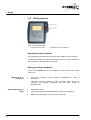
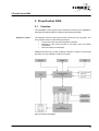
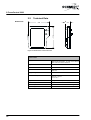
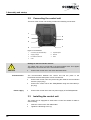
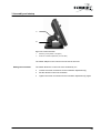
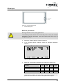
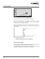
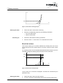
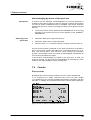
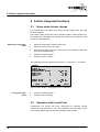
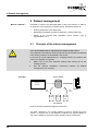
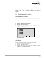
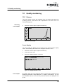
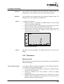
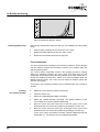
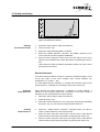
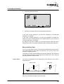
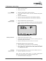
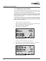
Operator’s manual
®
SCHMIDT PressControl 3000
SCHMIDT® press system with force/stroke-monitoring and
SCHMIDT® PressControl 3000
General
0.
General
Contact adresses
Germany
SCHMIDT Technology GmbH
Feldbergstr. 1
D-78112 St. Georgen
Tel.
Fax.
eMail
+49 (7724) 899-0
+49 (7724) 899-101
[email protected]
www.schmidttechnology.de
USA
SCHMIDT Technology Corp.
Cranberry Corporate Center
280 Executive Drive
USA-Cranberry Twp., PA 16066
Tel.
Tel.
Fax.
eMail
+1 (724) 772-46 00
+1 (800) 959-12 18
+1 (724) 772-46 88
[email protected]
www.schmidtpresses.com
Great Britain
SCHMIDT Technology Ltd
Unit 14/18 The Markham Centre
UK-Theale, Reading
Berks RG7 4PE
Tel.
Fax.
eMail
+44 (118) 9305-464
+44 (118) 9305-440
[email protected]
www.schmidttechnology.co.uk
Switzerland
SCHMIDT Technology GmbH
Niederlassung Schweiz
Gerbeackerstr. 8
CH-3210 Kerzers
Tel.
Fax.
eMail
+41 (0)31 755 40 71
+41 (0)31 755 40 73
[email protected]
www.schmidttechnology.ch
©
2007 SCHMIDT Technology GmbH
All rights reserved. Printed in the Federal Republic of Germany.
Version and revision date:
Version 1.3 of August 2007
2
SCHMIDT® PressControl 3000 – V1.3
General
Table of Contents
Documentation structure .................................................................................5
1
Safety ................................................................. 6
1.1
1.2
1.3
1.4
Designated use .....................................................................................6
Organisational measures of the system operator .................................7
Risks .....................................................................................................7
Safety devices.......................................................................................8
Operational status indicator ..................................................................8
Emergency Stop pushbutton.................................................................8
2
PressControl 3000............................................. 9
2.1
2.2
Function ................................................................................................9
Technical Data ....................................................................................10
3
Assembly and startup..................................... 11
3.1
3.2
3.3
Transport and storage.........................................................................11
Connecting the control unit .................................................................12
Installing the control unit .....................................................................12
4
Operation ......................................................... 14
4.1
4.2
4.3
4.4
Operating elements.............................................................................14
User interface......................................................................................14
System functions.................................................................................14
Softkeys and operating levels .............................................................15
Switching on and off............................................................................16
Reference run .....................................................................................16
5
Data Input ........................................................ 18
5.1
5.2
Default settings ...................................................................................18
Standard parameters overview...........................................................22
6
Text and system outputs ................................ 24
6.1
6.2
System outputs ...................................................................................24
Process data .......................................................................................24
7
Press processes.............................................. 25
7.1
Defining the press process .................................................................25
Press parameters................................................................................25
Return stroke criterion.........................................................................25
Stroke takeover (only two-hand control) .............................................26
Optimisation of the press process ......................................................27
Bend-Up (Yield Factor) .......................................................................27
7.2
SCHMIDT® PressControl 3000 – V1.3
3
General
7.3
7.4
Idle-stroke monitoring......................................................................... 30
Block limit window .............................................................................. 31
Acknowledging an incorrect pressing .................................................32
Acknowledging by means of external luminous button ...................... 32
Acknowledging by means of the reject box........................................ 33
Counter................................................................................................33
Piece counter ..................................................................................... 33
Pre-selection counter ......................................................................... 34
8
Further integrated functions .......................... 36
8.1
8.2
8.3
8.4
Setup mode for tool change ................................................................36
Operation with ControlTool .................................................................36
Taring the force value .........................................................................38
Parts inquiry ........................................................................................38
9
Dataset management ...................................... 40
9.1
9.2
Principle of the dataset management .................................................40
Managing multiple datasets ................................................................41
Creating and storing datasets ............................................................ 41
Load dataset....................................................................................... 41
Renaming dataset .............................................................................. 42
10 Quality monitoring .......................................... 43
10.1 Curves .................................................................................................43
Curve display...................................................................................... 43
Enlarging details................................................................................. 44
10.2 Tolerances...........................................................................................45
Reference data................................................................................... 45
Force tolerances ................................................................................ 46
Stroke tolerances ............................................................................... 47
Managing tolerances .......................................................................... 48
Move tolerance data........................................................................... 49
11 Maintenance and servicing............................. 51
11.1 Setting the force offset ........................................................................51
11.2 Calibrating the force sensor ................................................................52
11.3 Adjusting the stroke offset...................................................................54
12 Customer Service............................................ 56
4
SCHMIDT® PressControl 3000 – V1.3
General
Documentation structure
The operator’s manual for the press system is divided into the following
documentation modules:
®
Operator's Manual – SCHMIDT Press
•
•
•
Structure and function
Assembly and startup
Maintenance and servicing
®
Operator's Manual – SCHMIDT SafetyModule
•
•
•
Structure and function
Mounting and startup
Maintenance and servicing
®
Operator's Manual – SCHMIDT PressControl 3000
•
•
•
•
•
Structure and function
Assembly and startup
User interface
Practical operation
Maintenance and servicing
®
Technical documentation – SCHMIDT press system
•
•
•
•
•
Optional
®
User Manual – SCHMIDT ControlTool - Teil 1
•
•
•
•
•
Optional
®
Fundamentals
PLC programming
Range of commands
®
User Manual – SCHMIDT SPC
•
•
•
SCHMIDT® PressControl 3000 – V1.3
Installation
User interface
Project and dataset management
Quality monitoring
Update and service
User Manual – SCHMIDT ControlTool - Teil 2
•
•
•
Optional
Circuit diagram and pneumatic plan
Manufacturer’s Declaration or Declaration of Conformity
Spare part lists
Test certificates
Description of special functions
Structure and function
User interface
Practical operation
5
1 Safety
1 Safety
The press system has been built, manufactured and tested ex works for its
function and safety in accordance with current safety regulations and stateof-the-art methods. This guarantees its operational safety. Nevertheless the
press system can involve risks, if
•
it is not used in accordance with its designated use,
•
it is operated by untrained personnel,
•
it is modified or converted incorrectly or
•
the safety regulations are not observed.
The press system may only be used if it is in technically perfect condition. All
required safety devices must be in place and fully functional.
Apart from the instructions listed in this operating manual, the current
country-specific safety and accident prevention regulations provided by law
apply.
1.1
Designated use
The control unit may be operated on a SCHMIDT PneumaticPress or a
SCHMIDT HydroPneumatic Press only in connection with the SCHMIDT
SafetyModule.
The control unit may only be used, together with the above mentioned
components, for the following press processes:
•
Assembling
•
Forming
•
Riveting
•
Pressing
•
Crimping
•
Flaring
•
Bonding
•
Punching
Using the system for purposes other than those described above is contrary
to the designated use. The manufacturer cannot be held liable for any
damage resulting from such a use. The risk lies entirely with the user.
Do not make any changes to the press system which could impair safety.
The manufacturer cannot be held liable for any damage resulting from such
a use. The risk lies entirely with the user.
Designated use also includes:
6
•
compliance with the documentation
•
compliance with the inspection and maintenance measures
SCHMIDT® PressControl 3000 – V1.3
1 Safety
1.2
Organisational
operator
measures
of
the
system
Use as safety component
!
DANGER
If the control has been delivered not ready for use (with a Declaration of
Conformity according to Annex II b of the Machinery Directive 98/37/EC) the
operator or the system manufacturer must ensure observance of the safety
regulations.
Of the safety regulations, observe in particular the Machinery Directive
98/37/EC and the standards DIN EN 349, DIN EN 292 and DIN EN 294.
The operator must make sure that
•
the instructions contained in the operating manual concerning
startup, operation and maintenance are observed.
•
the press system is properly operated, tested and maintained and
the responsibilities for these tasks are clearly set out.
•
those persons responsible for activities on the press system have
read this operating manual and, in particular, chapter “1 Safety”,
before starting work. This also applies to persons who work only
occasionally.
•
this operating manual is always kept within easy reach at the
workplace.
1.3
Risks
The press system is constructed so as not to put any persons at risk when
used in accordance with its designated use. However, certain parts of the
press system cannot be protected without limiting its functionality and
usability. Thus, despite constructional safety measures, a residual danger
remains.
Safe press operation requires the interaction of press, control unit, tools,
safety devices and conduct of the user in accordance with the safety
measures.
Injuries or death caused by touching live parts
!
DANGER
During assembly and repair work you may come into contact with parts
which carry dangerous voltage in operation. Touching live parts may cause
death.
Any work on the electrical system or equipment must be carried out
only by trained electricians or by specially instructed persons under the
control and supervision of a trained electrician and in accordance with
the applicable electrical engineering rules and regulations.
SCHMIDT® PressControl 3000 – V1.3
7
1 Safety
1.4
Safety devices
1
2
Figure 1-1: PressControl 3000
1
Operational status indicator
2
EMERGENCY STOP pushbutton
Operational status indicator
The operational status indicator is located on the display of the control unit.
The status indicator is lit in green permanently when the press system has
been switched on and is ready for operation.
Emergency Stop pushbutton
There is an EMERGENCY STOP pushbutton on the control panel of the
control unit.
What to do in an
emergency
Press the Emergency Stop pushbutton immediately in case of
emergency.
The press system is taken to a safe operating state. All moving
machines are stopped immediately and the press system is
depressurised.
Start after Emergency
Stop
Eliminate the error.
Unlock the Emergency Stop pushbutton by turning and pulling it.
Switch the press system on again at the control unit.
8
SCHMIDT® PressControl 3000 – V1.3
2 PressControl 3000
2 PressControl 3000
2.1
Function
®
The SCHMIDT Press System with force/stroke monitoring and SCHMIDT
PressControl 3000 operates according to the following principle:
Sequence control
®
The sequence control of the press process is done via a PLC program. The
PLC program carries out the following functions:
•
•
•
Control of the process data acquisition sequence
Monitoring of the press process on the basis of the set quality
parameters
Plain text output on the display.
Additional functions (e.g. feeds, workpiece detection, sorting of OK and Not
OK parts, etc.) are effected via the PLC program.
Figure 2-1: Block circuit diagram
SCHMIDT® PressControl 3000 – V1.3
9
2 PressControl 3000
2.2
Technical Data
Dimensions
~ 80
~ 320
~ 290
Figure 2-2: Dimensions of the control unit
Technical Data
10
Display
Liquid crystal display (128 x 240 pixels) with
background illumination, 16 lines of 40 columns
each, with touch screen functions
Keypad
Touch screen
Interfaces
USB
Mains connection
100 up to V AC / 50 up to 60 Hz max. back-up
fuse 16 A
Supply voltage
24 V DC
Current consumption
350 mA / 230 V or
700 mA / 110 V or
2.5 A / 24 V
Weight
5.5 kg incl. external power supply unit
Ambient temperature
0 up to 40° C
Air humidity
up to max. 95% relative, non condensing
Protection type
IP 54
SCHMIDT® PressControl 3000 – V1.3
3 Assembly and startup
3 Assembly and startup
Safety instructions
!
The control unit may only be installed and serviced by setup engineers
who have been commissioned and trained by the company.
CAUTION
Any work on the electrical equipment of the press must be carried out
only by trained electricians or by specially instructed persons under the
control and supervision of a trained electrician and in accordance with
the applicable electrical engineering rules and regulations.
Check the control unit, accessories and all supply lines for possible
damage prior to each startup.
Switch off a defective press immediately or depressurise the pneumatic
system immediately and have the malfunctions repaired as soon as
possible.
3.1
Delivery
Transport and storage
Check the delivered press system components for visible transport
damage.
Report any transport damage immediately to the following authorities:
- the forwarding agent
- the dispatch department of SCHMIDT Technology.
Keep the original packaging for later transport and/or for further storage.
Transport
Use the original packaging for further transport (service, repairs….).
Ensure proper packaging of the components.
Storage
Ensure proper packaging of the components, if they must remain
unused for longer periods.
Store the control unit in upright position (do not place on the display)
Store the control unit in such a way that it is not subject to large
fluctuations in temperature. Otherwise, the resulting condensed
moisture may cause corrosion on critical press or control unit
components.
Please observe the information on the ambient conditions in chapter
"2.2 Technical Data".
SCHMIDT® PressControl 3000 – V1.3
11
3 Assembly and startup
3.2
Connecting the control unit
The back of the control unit housing contains the following connections:
1
5
2
6
3
7
4
Figure 3-1: Connections
1
not used (only ManualPress)
5
Inputs/outputs
2
Supply voltage
6
Service
3
Force/stroke sensors
7
USB
4
CAN
Damage to the force/stroke sensors
!
The cables may only be connected in the de-energized state. This applies
especially to the connection of the force/stroke sensors.
CAUTION
Communication
Connect the control unit in the order described below.
The communication between the control unit and the press or the
force/stroke sensors takes place via two connections.
Connect the control unit to the press using the cable for the force/stroke
sensors (12-pin plug).
Connect the control unit to the SafetyModule using the CAN-cable (5pin plug).
Connect the control unit to the 24V power supply of the SafetyModule.
Power supply
3.3
Installing the control unit
The control unit is equipped ex works with a control unit holder for table or
wall mounting.
Insert the control unit in the table holder.
Tighten the fastening screw (1).
12
SCHMIDT® PressControl 3000 – V1.3
3 Assembly and startup
1
2
Figure 3-2: Control unit holder
1
Fastening screw (hidden in the figure)
2
Screw for inclination adjustment (on both sides)
The holder adapter in the control unit must not be removed.
Setting the inclination
The holder allows the control unit to be swivelled by 70°.
Loosen the screw connections for the inclination adjustment (2).
Set the desired control unit inclination.
Tighten the screw connections for the inclination adjustment (2) again.
SCHMIDT® PressControl 3000 – V1.3
13
4 Operation
4 Operation
4.1
Operating elements
®
The SCHMIDT PressControl 3000 press system is basically operated by
means of the following operating elements:
1
6
2
3
7
4
8
5
9
10
Figure 4-1: Operating elements
1
LCD with touch screen
6
On/Off pushbutton
2
“Set contrast” key
7
EMERGENCY STOP pushbutton
3
Softkeys
8
System function keys
4
“Change operating level” key
9
Cursor keys
5
Numeric keys
10
"Acknowledge incorrect pressing" key.
4.2
User interface
System functions
Using the system function keys you can directly access the most important
display modes having system functions.
1
2
3
4
5
Figure 4-1: System function keys
Datasets
14
1
Datasets
4
Data Input
2
System Options
5
Data Output
3
Curve Output
In this display mode, you have access to the commands for dataset
management. They include commands for creating, saving, renaming and
loading datasets.
SCHMIDT® PressControl 3000 – V1.3
4 Operation
System Options
In this display mode, you have access to the commands for the system
settings of the control. They include settings for time, date, alarms, machine
parameters, interface definitions, etc.
Curve Output
In this display mode, you have access to the commands for displaying the
recorded curve. They include commands for zooming, tolerance data input,
and for displaying the curve.
Data Input
In this display mode, you have access to the machine parameters for
operating the press system. They include parameters for the return stroke,
for process data acquisition, or for quantities.
Data Output
In this display mode, the operator can view information on the state of the
press system. This information includes data on the system condition,
quantities, incorrect pressings, etc.
You can find detailed information concerning the most important menu
commands in the following chapters.
Softkeys and operating levels
®
The SCHMIDT PressControl 3000 press system is provided with a PLC
program having a large number of basic functions. They can be activated by
means of softkeys on the touch screen.
Softkeys
The following table describes the softkeys included in the standard PLC
program.
Operating level
1
2
3
Changing
operating level
Softkey
Description
CtrON
Switch on control unit
CtrOFF
Servic
Switch off control unit
“Setup” operating mode (switch press to airless mode).
PCTon
Switch pre-selection counter on
PCToff
Switch pre-selection counter off
PCT-0-
Set pre-selection counter to zero
CNT-0-
Set piece counter to zero
ACK
Acknowledge fault
Ref.
Carry out a reference run
The control starts automatically with operating level “1”.
Press the "Change operating level" key (see Figure 4-1). This is how
you switch to the next higher/lower operating level.
All softkeys labelled with asterisk have not been assigned. The assignment
of the softkeys and their allocation to an operating level is done by the PLC
program. For further information concerning the programming of additional
®
softkeys, please see the "User Manual - SCHMIDT ControlTool - Part 2".
SCHMIDT® PressControl 3000 – V1.3
15
4 Operation
4.3
Switching on and off
After all mounting and installation tasks are complete, the press system can
be started.
As the control unit is supplied with voltage from the SafetyModule, it can also
be switched on or off by means of the main switch of the SafetyModule.
Start the press system as described in chapter “3.4 Switching on and
®
off” in the "Operating Manual – SCHMIDT SafetyModule".
PC-DEAC
(1)
Dataset 1
Control Off!
1
CtrON
CtrOFF
...
...
Servic
Figure 4-3: Display after the self-test
Change to operating level 1.
Select the “CtrON” softkey.
The system first carries out a self-test and then automatically starts the
delivered PLC program. After the system has been switched on, the
status indicator is lit and the message “Machine ok” appears on the
display.
4.4
Reference run
After switching on the control unit, a reference run must be carried out. This
is shown by the “Operate press <Ref>” message on the display.
PC-DEAC
(1)
Dataset 1
Machine ok.
Operate press <Ref>
1
CtrON
CtrOFF
...
...
Servic
Figure 4-4: Display after switching on
16
SCHMIDT® PressControl 3000 – V1.3
4 Operation
Carry out a working stroke. After reaching the reference point, the press
moves automatically to the TDC position.
PC-DEAC
Quantity ok
Quantity nok
Quantity
:
:
:
Reached force
Reached stroke
:
:
1
CtrON
(1)
Dataset 1
Machine ok.
2-Hand-Release
Returnstroke at stroke:
CtrOFF
30.000 mm
0 pcs
0 pcs
0 pcs
0 N
.000 mm
...
...
Servic
Figure 4-5: Display after the reference run
Manual reference run
In general you can always carry out a reference run manually. During this
operation the control unit must not be switched off.
Change to operating level 3.
Select the “Ref” softkey.
Perform the reference run, as described above.
SCHMIDT® PressControl 3000 – V1.3
17
5 Data Input
5 Data Input
Various parameters (data input, system options, etc.) can be input directly at
the control unit.
Select the "Data Input" system function key.
Calling data input
Input Dataset 1
0
1
2
3
4
5
6
7
8
9
Mode : F=0,s=1,t=2,m=3
Returnstroke Force
Returnstroke Stroke
Returnstroke Time
Start/Stop PDA
Counter access
Target count
Alarmtime quan. reached
Alarmtime press error
BDC-stroketakeover
1
CtrON
CtrOFF
...
1
1500
30.000
2.0
5.000
1
20
3.0
3.0
20.000
...
N
mm
sec
mm
sec
sec
mm
Servic
Figure 5-1: Data input
Mark the desired parameter. The selected line is given a dark
background.
Press the "Enter” key. The previously set value is deleted and the
cursor blinks at the input position.
Enter the desired value using the numeric keys. Input errors can be
corrected by means of the "Left" cursor key.
Confirm the entry by pressing the “Enter” key.
Scrolling
10 input parameters can be displayed simultaneously on the display of the
control unit. You can move from one parameter to the next by using the “Up”
/ “Down” cursor keys. With the "Left" and "Right" cursor keys, you can jump
from on block of 10 to the next.
5.1
Default settings
Contrast
The display is blank
!
CAUTION
With increasing operating temperature, the contrast of the display
diminishes. Since nothing can be seen any longer on the display, the user
may think that the control is defective.
Check if the contrast is set correctly using the "Contrast setting" key.
18
SCHMIDT® PressControl 3000 – V1.3
5 Data Input
1
Figure 5-1: "Contrast setting" keys
1
"Contrast setting" keys
Machine parameters
Wrong evaluation of the quality parameters
!
CAUTION
The sensitivity of the sensors of the connected press is set by the machine
parameters. The set parameters have been tested and should only be
changed by experts.
Select the "System Options" system function key.
In the "System Options" submenu, select the "Machine Parameter"
selection.
Machine Parameter
Res. Stroke Sensor
Max. Stroke
Res. Force Sensor
Maximum Force
Graphic init
1
CtrON
CtrOFF
[I/mm*10]
[mm]
[I/kN]
[kN]
...
...
2000
100
400
10
Servic
Figure 5-3: Machine parameters
Modify the corresponding parameters according to the sensor type.
Parameter
5 kN
20 kN
100 kN
160 kN
Res. Stroke Sensor
2000
2000
2000
2000
Max. Stroke
100
100
100
100
Res. Force Sensor
400
100
20
16
10
20
100
125
Maximum Force
Please refer to chapter “5.1 Press data” in the operating manual of the
press to find out which force sensor is integrated in which press.
SCHMIDT® PressControl 3000 – V1.3
19
5 Data Input
Confirm the entry of the parameters by pressing the “Graphic init” key.
UE470 address
The CAN gateway address must be correctly set for the communication
®
between the control unit and the SCHMIDT SafetyModule. The address
“10“ is set by default in the CAN gateway and also in the control unit.
Select the “System menu” system function key.
Select the “Service” submenu in the “System Options” menu.
Service
Ident
Adress UE470
1
CtrON
10
CtrOFF
...
...
Servic
Figure 5-4: UE470 address
The address is set in the CAN gateway by means of two rotary switches.
Access
Assigning an access code and privilege level
!
CAUTION
The control is delivered ex works with complete access rights and with the
access code "0".
Limit access to the individual areas.
Assign a new access code. This code consists of a number with a
maximum of 9 digits.
These settings are made in the "System Options" display mode.
Select the "System Options" system function key.
Select the "Access Codes" menu.
Enter the access code (default setting = "0").
20
SCHMIDT® PressControl 3000 – V1.3
5 Data Input
Access Codes
User Data
Monitoring Data
System Options
Com Port
Access Code
1
CtrON
CtrOFF
Access
Access
Access
Access
0
...
...
Servic
Figure 5-2: "Access Codes" submenu
Changing access code
Select the "Access Code" command.
Assign a new access code. This code consists of a number with a
maximum of 9 digits.
Changing access
authorization
Select the access area which you would like to change.
Confirm the selection with the "Enter" key. The setting is changed from
"Access" to "No access" or visa versa.
Other features
Date + time
These settings are made in the "System Options" display mode.
In the "System Options" submenu, select the "Date/Time" selection.
Select the "Date" command and enter the date in the format
"DD.MM.YY".
Select the "Time" command and enter the date in the format
"HH.MM.SS".
Alarms
You can define two alarm times (Time Alarm 1 and Time Alarm 2) that
trigger an alarm daily. You further have the possibility to define an alarm
time (Time Alarm 3) that is only triggered on a certain date (Date Alarm 3).
In the "System Options" submenu, select the "Date/Time" selection.
Select the desired alarm in the "Alarm" menu.
Enter a time in format "HH.MM.SS" and the date in format "DD.MM.YY".
When the set alarm time is reached, a marker is activated in the PLC
program. By querying this marker, you can initiate other actions. For further
®
information, please see the "User manual - SCHMIDT ControlTool - Part 2".
Volume
You can set the volume of the "key click" (acknowledgement when a key is
pressed) and the volume of the alarm functions. You can enter values of "0"
to "255" for both volumes.
Test the volumes under the usual background noise conditions to check if
the alarm can be heard during normal production operations.
SCHMIDT® PressControl 3000 – V1.3
21
5 Data Input
In the "System Options" submenu, select the "Speaker Volumes"
selection.
Select the "Volume Keyclick" command and enter the desired value.
Select the "Volume Alarm" command and enter the desired value.
5.2
Standard parameters overview
A total of 60 input parameters can be defined by means of the PLC program.
The following table describes the parameters included in the standard PLC
program.
Malfunctions of the press system
!
CAUTION
Parameters 9 to 11 / 51 to 59 are adapted ex works to the respective press
system and should only be changed after consultation with SCHMIDT
Technology.
No. Parameter
Description
0
Mode: F=0,s=1,t=2,m=3
This parameter determines according to which criterion the return stroke is to be started ( 0=force,
1=stroke, 2=time, 3=manual).
1
Returnstroke Force
Force at which the return stroke is to be started.
2
Returnstroke Stroke
Stroke at which the return stroke is to be started.
3
Returnstroke Time
This parameter can be used to set a dwell time for the return stroke function of the press (0 to 600
sec). Only after this time has expired will the return stroke be started.
4
Start/Stop PDA
Stroke from which the process data acquisition begins / is stopped (return stroke)
5
Counter access
This parameter defines whether the piece counter can be reset or not (0=disabled, 1=enabled)
6
Target count
As soon as the set nominal piece number is reached, an alarm will be output.
7
Alarmtime quan. reached
Duration (0 to 10 sec.) for how long the alarm should sound when the number of pieces has been
reached.
8
Alarmtime press error
Duration (0 to 30 sec.) for how long the alarm should sound in case of an incorrect pressing.
9
BDC-stroketakeover
From this stroke, the two-hand button can be released, as a result of which the stroke will be
completely carried out. The stroke has to be set in such a way that the dangerous closing
movement is finished when the stroke has been reached.
10
Servicetime
In the “Setting the time” mode the two-hand button has to be pressed for this time (0 to 20 sec.).
After that the press is depressurised.
11
Alarm time STO
Duration (0 to 5 sec.) for how long the alarm should sound when the stroke signal in parameter 9
has been reached and the pressure switch is switched on.
13
Block-Limit-Window
This parameter defines whether the “Block limit window” function is active or not (0=active,
1=inactive)
14
min. force limit
If the “Block limit window” function is active, this parameter defines the minimum force which must
be reached.
15
max. force limit
If the “Block limit window” function is active, this parameter defines the maximum force which may
be reached.
16
min. stroke limit
If the “Block-limit window” function is active, this parameter defines the minimal stroke which must
be reached.
17
max. stroke limit
If the “Block limit window” function is active, this parameter defines the maximum stroke which
may be reached.
22
SCHMIDT® PressControl 3000 – V1.3
5 Data Input
No. Parameter
Description
25
idle-stroke monitoring
This parameter defines whether the “idle-stroke monitoring” function is active or not (0=active,
1=inactive)
26
max.force idle-stroke
If the “idle-stroke monitoring” function is active, this parameter defines the maximum allowed force
which must not be reached.
27
stroke for idle-stroke
If the “idle-stroke monitoring” function is active, this parameter defines the stroke which has be
controlled.
30
PC on/off
This parameter defines whether the control unit has to be connected to an external PC for
operation.
31
SPC on/off
This parameter determines whether the "SPC " has been switched on or not (0=off, 1=on).
40
Move tolerance on/off
This parameter defines whether the “Offset of tolerance data” function is active or not (0=active,
1=inactive)
41
Ref-pos. stroketol.1
This parameter defines the intersection of the reference curve with the stroke tolerance 1.
42
Force tare on/off
The "Force tare" function is used to tare the force value after each stroke to the value "0".
45
Part check on/off
This parameter defines whether a part is available on an optionally mounted workpiece fixture or
not (0=active, 1=inactive)
47
ACK n.ok-box on/off
This parameter defines whether a part has fallen into an optionally mounted reject box or not
(0=active, 1=inactive).
50
Bend up [mm/kN]
The measured bending constant eliminates the elastic properties of the overall system.
51
BDC signal (I1.3) exist.
This parameter defines whether the press is provided with a cylinder switch or not (0=not provided,
1=provided)
52
TDC signal (I1.4) exist.
dto
54
Sensor type
Enter the sensor type (5 kN, 20 kN, 100 kN or 160 kN) according to the activated press type.
55
Adm offsetdrift pos.
The allowed offset drift is set by default to 50 increments. If the value of the force measuring
system exceeds the nominal value or drops below it by 50 increments when the control unit is
switched on, the error message “Error force measuring system” appears on the display. This error
message indicates a possible defect of the force measuring system (e. g. sensor deformed). The
force measuring system should be immediately checked and calibrated again!
56
Adm offsetdrift neg.
dto.
57
Aq. distance PDA force
The “increment” of the process data acquisition determines the frequency of the written measuring
points (standard value 5 inc., i.e., every 5 increments one measuring point). The larger the value,
the fewer measuring points are written.
58
Aq. distance PDA stroke
dto.
59
Offset stroke
The “Offset stroke” value is machine specific. The measured value for the activated machine is
included in the test certificate.
SCHMIDT® PressControl 3000 – V1.3
23
6 Text and system outputs
6 Text and system outputs
6.1
System outputs
Select the “Data Output” system function key.
Activating data output
PC-DEAC
Quantity ok
Quantity nok
Quantity
:
:
:
Reached force
Reached stroke
:
:
1
CtrON
(1)
Dataset 1
Machine ok.
2-Hand-Release
Returnstroke at stroke:
CtrOFF
30.000 mm
17 pcs
4 pcs
21 pcs
2138 N
40.432 mm
...
...
Servic
Figure 6-1: View “Output 1”
In this display mode, the operator can view information on the states of the
press system. This information includes system messages, such as, for
example, control on/off, piece numbers, incorrect pressings, etc.
6.2
Changing view
Process data
In another view, you can see the current process data of the sensors and the
evaluation of the monitoring windows.
By pressing the “Data Output” system function key, you can toggle
between the two views.
(2)
Dataset 1
Force
Stroke
Increment force
Increment stroke
Offset force
Average force wind.F1
Average force wind.F2
Average force wind.F3
Average force wind.F4
Desired range str.tol1
Desired range str.tol2
1
CtrON
CtrOFF
...
0
1.030
0
112
19
N
mm
inc
inc
inc
0 N
0 N
0 N
0 N
.000 mm
.000 mm
...
Servic
Figure 6-2: View “Output 2”
The average values of the force tolerances or the passages of the stroke
tolerances are displayed only for the defined tolerances.
24
SCHMIDT® PressControl 3000 – V1.3
7 Press processes
7 Press processes
7.1
Defining the press process
A press process is defined by the press parameters “force” and “stroke” and
the selection of the return stroke criterion. These parameters are entered in
the “Data Input” display mode and are automatically linked to the PLC
program.
These settings are made in the "Data Input" display mode.
Select the "Data Input" system function key.
Press parameters
The definition of a press process always requires “force” and “stroke” to be
entered. Both parameters are monitored during the press process.
Select the "Returnstroke Force" parameter.
Enter the force that is not to be exceeded during the press process.
Select the "Returnstroke Stroke" parameter.
Enter the stroke that is not to be exceeded during the press process.
Return stroke criterion
The return stroke criterion determines the order in which “force” and “stroke”
are monitored.
"force"
return stroke criterion
When performing the press process with the “force” return stroke criterion,
primarily the "Returnstroke Force" parameter and secondarily the
"Returnstroke Stroke" parameter are monitored.
Select the "Data Input" system function key.
Select the "Mode: F=0, s=1, t=2, m=3" parameter.
Enter the value "0".
If in a press process the set force is not reached, but the set stroke is
exceeded, the error message: "P2:RS stroke exceeded!" is displayed.
SCHMIDT® PressControl 3000 – V1.3
25
7 Press processes
"stroke"
return stroke criterion
When performing the press process with the “stroke” return stroke criterion,
primarily the "Returnstroke Stroke" parameter and secondarily the
"Returnstroke Force" parameter are monitored.
Select the "Data Input" system function key.
Select the "Mode: F=0, s=1, t=2, m=3" parameter.
Enter the value "1".
If in a press process the set stroke is not reached, but the set force is
exceeded, the error message: "P1:RS force exceeded!" is displayed.
"time"
return stroke criterion
When performing the press process with the return stroke criterion “time“,
the press moves to the BDC position. When the time set in parameter
"Returnstroke Time" has expired, the press moves to the TDC position.
Select the “Data Input” system function key.
Select the "Returnstroke Time" parameter.
Enter the time after which the return stroke has to be started.
Select the “Mode: F=0, s=1, t=2,m=3" parameter.
Enter the value “2”.
If in a press process the BDC position is not reached, the error message
"BDC not reached->ACK“ appears.
"manual"
return stroke criterion
When the press process is performed with the return stroke criterion
“manual“ the press moves to the BDC position. The press remains in the
BDC position until it is acknowledged by means of the external luminous
button. Then the press moves to the TDC position.
Select the “Data Input” system function key.
Select the “Mode: F=0, s=1, t=2,m=3" parameter.
Enter the value “3”.
Stroke takeover (only two-hand control)
The stroke takeover is the moment of the working stroke from which the
closing movement of the working stroke is no longer interrupted upon
releasing the two-hand control.
This stroke takeover has to be set in such a way that the dangerous closing
movement is finished upon reaching this switch.
A dangerous closing movement is that part of the movement of closing tools
that may cause injures. It is finished, when moving parts and fixed parts
have approached each other to such an extent that no more injury is
possible (6 mm).
26
SCHMIDT® PressControl 3000 – V1.3
7 Press processes
PneumaticPress
The stroke takeover is monitored in two channels by means of
•
•
a pressure switch, which monitors the lower pressure chamber and
a cylinder switch in the bottom dead centre (BDC)
The pressure switch has been set to a fixed value ex works and must not be
adjusted.
Set the cylinder switch for the stroke takeover. For further information,
please refer to chapter “3.7 Setting the press stroke takeover” of the
“Operator's manual – SCHMIDT PneumaticPress”.
Check if the control unit settings for the existing cylinder switch(es) are
correct.
If necessary, adapt the “BDC signal (l1.3) exist.” parameter and the
“TDC signal (l1.4) exist.".
HydroPneumaticPress
The stroke takeover is monitored in two channels by means of
•
a pressure switch, which recognises the switchover from rapid
approach stroke to power stroke and of
• the “BDC stroketakeover” parameter in the Press Control 3000
control unit.
The pressure switch has been set to a fixed value ex works and must not be
adjusted.
The “BDC stroketakeover” parameter has to be set in such a way that
the dangerous closing movement is finished upon reaching this
position.
7.2
Optimisation of the press process
Bend-Up (Yield Factor)
Every press system has a force-dependent deflection. This results from the
elastic deflection of the machine, the tool, and the workpiece.
For stroke-dependent press operations without a positive stop (freely
positioned), possible bend-up may lead to positioning errors due to
dispersion of the press forces. Positioning accuracy in the range of 0.01 mm
are practically impossible to attain without compensation of the deflection
constants.
The drive control calculates the axis-specific and application-specific
deflection constant in real-time. The representation of the deflection in the
following figure is strongly exaggerated.
SCHMIDT® PressControl 3000 – V1.3
27
7 Press processes
F
2
2
F
1
2
Figure 7-1: Positioning error due to deflection or compression
Calculate deflection
1
Deflection
2
Compression
After you have completely set up the press system (with tools), you can
calculate the deflection. This can be done based upon a normal press
sequence.
Select the "Curve Output" system function key.
Press a workpiece and record the force/stroke curve.
Enlarge the curve section so that the press start and press end are
visible.
2.00
F[kN]
1.50
1.00
∆F
.500
0.0
∆s
10.00
20.00
s[mm]
40.00
30.00
Figure 7-2: Calculate deflection
Calculate the deflection.
Sample calculation:
Stroke difference ∆s = 2 mm
Force difference ∆F = 1,7 kN
Deflection ∆s/∆F
Enter deflection
= 1,176 mm/kN
Select the "Data Input" system function key.
Select the "Bend up [mm/kN]" parameter.
Enter the calculated value
28
SCHMIDT® PressControl 3000 – V1.3
7 Press processes
Before - After
Press another workpiece and record the force/stroke curve again.
2.00
F[kN]
1.50
1.00
.500
0.0
10.00
20.00
30.00
s[mm]
40.00
Figure 7-3: Force curve before and after deflection compensation
After deflection compensation is performed, the elastic properties of the
entire system (machine, tool, workpiece) will be eliminated in each
press operation in real time.
Wrong parts evaluation
!
ATTENTION
The maximum stroke (smax) separates the working stroke from the return
stroke. An overcompensation can result in a shift of smax within the force
curve.
If a return stroke tolerance in the diagram is above smax, it is (by definition)
part of the working stroke. Consequently, the measured value will not pass
correctly through the tolerance window, so that "O.K." parts will be identified
as "Not O.K. " parts.
Avoid an overcompensation.
Make sure to place the tolerance in a "safe" area, in which the
measured value will pass correctly through the tolerance window in
any case.
Overcompensation
By definition, the return stroke begins after reaching of smax.
2.00
F[kN]
1.50
1.00
W1
.500
0.0
9.17
18.34
s[mm]
36.39
27.52
smax
Figure 7-4: Stroke tolerance of the return stroke
Overcompensation (increased factor of deflection constants in mm/kN) may
lead to a shifting of smax within the force curve.
SCHMIDT® PressControl 3000 – V1.3
29
7 Press processes
2.00
F[kN]
1.50
1.00
W1
.500
0.0
9.17
18.34
s[mm]
36.39
27.52
smax
Figure 7-4: Stroke tolerance in working stroke with overcompensation
If the return stroke tolerance in the diagram is set above smax, it is (by
definition) in the working stroke. Consequently, “OK parts” will be interpreted
as “Not OK parts” and assigned accordingly.
Since the working stroke will change to the return stroke very rarely at a
fixed position, it may be difficult to find a suitable position for a tolerance in
the return stroke.
F
1
s
2
Figure 7-5: Different positions of smax
1
Change from the working stroke to the return stroke (Pressing 1)
2
Change from the working stroke to the return stroke (Pressing 2)
Idle-stroke monitoring
This function allows you to monitor whether a max. allowed force (Fmax) has
not been reached or exceeded up to a certain stroke (sx).
If in a press process the max. allowed force is reached, an error message
will appear, and the press will move back to the TDC position.
30
SCHMIDT® PressControl 3000 – V1.3
7 Press processes
F
Fmax
s
sx
Figure 7-7 Idle-stroke monitoring principle
Defining the limits
Define the limits of idle-stroke monitoring.
Enter the corresponding values for the following parameters:
•
•
Switching on
max. force idle-stroke
stroke for idle-stroke
Select the “idle-stroke monitoring” parameter.
Enter the value “1”. Enter value “0” to deactivate the function.
Block limit window
This function allows you to monitor whether the reversal point of the force
curve (change from the working stroke to the return stroke) is within certain
limits.
If in a press process one of the determined limits has been reached, an error
message will appear indicating which limit has not been observed.
F
Fmax
Fmin
s
smin
smax
Figure 7-8: Block limit -window principle
In the control unit, no window is displayed. The limits are monitored by the
parameters only.
Defining the limits
Define the limits of the block limit window.
To do so, enter the corresponding values for the following parameters:
SCHMIDT® PressControl 3000 – V1.3
31
7 Press processes
•
•
•
•
min. force limit
max. force limit
min. stroke limit
max. stroke limit
Select the “Block-Limit-Window" parameter.
Switching on
Enter the value “1”. Enter value “0” to deactivate the function.
7.3
Acknowledging an incorrect pressing
An incorrect pressing can be acknowledged by pressing the "ACK" softkey.
Change to operating level 2.
Press the "ACK" softkey.
or
Press the "Acknowledge incorrect pressing" key.
Acknowledging by means of external luminous button
In addition to the options of acknowledging an error described above, for
severe production conditions, an external luminous button can be used to
acknowledge an incorrect pressing.
Connect the external luminous button for acknowledging incorrect
®
pressing to the relevant input (see circuit diagram) of the SCHMIDT
SafetyModule.
Now the error messages can also be acknowledged using the external
luminous button.
Acknowledging via
luminous button only
If you want to acknowledge error messages exclusively by means of the
external luminous button, you have to switch on additionally the “ACK n.okbox on/off” parameter.
Select the "Data Input" system function key.
Select the " ACK n.ok-box on/off" parameter.
Enter the value "1". To switch the function off again, enter the value "0".
32
SCHMIDT® PressControl 3000 – V1.3
7 Press processes
Acknowledging by means of the reject box
Prerequisite
A function for the automatic acknowledgement of incorrect pressings is
included in the scope of delivery of the PLC program. However, this function
can only be used if a additional sensor is available. This sensor will detect
whether the part of an incorrect pressing has fallen into a rejects box (Not
OK box).
Connect the sensor for the automatic acknowledgement of an incorrect
®
pressing to the relevant input (see circuit diagram) of the SCHMIDT
SafetyModule.
Switching on the
rejects box
Select the "Data Input" system function key.
Select the "ACK n.ok-box on/off" parameter.
Enter the value "1". To switch the function off again, enter the value "0".
As soon as the function is switched on, the input is queried as to whether a
part of an incorrect pressing has fallen into a connected rejects box (n.okbox). This ensures that a "Not OK part" cannot continue the production
process. The message "Press error! ACK" is acknowledged automatically as
soon as the input transmits a signal.
If the function "Acknowledging by means of the reject box" is used, the
incorrect pressing can no longer be acknowledged by pressing the "ACK"
softkey or the "Acknowledge incorrect pressing" key.
7.4
Counter
Piece counter
By default, this counter is always switched on in the control as-delivered.
If, for monitoring the quality, tolerances have been set (see chapter
"10.2 Tolerances"), the counter will distinguish between "OK parts" and "Not
OK parts". In addition, the produced total number of pieces will be displayed.
PC-DEAC
Quantity ok
Quantity nok
Quantity
:
:
:
Reached force
Reached stroke
:
:
2
PCTon
(1)
Dataset 1
Machine ok.
2-Hand-Release
Returnstroke at stroke:
PCToff
PCT-0-
30.000 mm
17 pcs
4 pcs
21 pcs
2138 N
40.432 mm
CNT-0-
ACK
Figure 7-6: View of "Output 1" with default piece counter
SCHMIDT® PressControl 3000 – V1.3
33
7 Press processes
Incorrect
Fehlpressung
pressing
Reset
Acknowledge the incorrect pressing. After that, you will be able to
continue the work.
If required, change to operating level 2.
When you want to reset the piece counter, press the "CNT-0-" softkey.
Locking
You can lock this counter and prevent the piece counter from being reset.
Select the "Data Input" system function key.
Select the "Counter access" parameter.
Enter the value "0".
Pre-selection counter
A pre-selection counter is integrated into the control unit in case the lot/batch
sizes to be produced are always the same.
As soon as the set nominal piece number is reached, an alarm sounds. If,
for monitoring the quality, tolerances have been set (see chapter
"10.2 Tolerances"), the counter will distinguish between "OK parts" and "Not
OK parts".
Setting
The nominal piece number and/or the duration of the alarm can be set in the
data input, depending on the privilege level.
Select the "Data Input" system function key.
Select the "Target count" parameter.
Enter the desired piece number.
Select the "Alarmtime quan. reached" parameter.
Enter the desired duration of alarm in seconds.
Switching on
After you have set the pre-selection counter, you can switch the preselection counter on.
If required, change to operating level 1.
Press the "PCTon" softkey.
PC-DEAC
(1)
Dataset 1
Machine ok.
2-Hand-Release
Returnstroke at stroke:
30.000 mm
Preselect target count:
Preselect count
:
Quantity nok actual
:
Reached force
Reached stroke
2
PCTon
PCToff
:
:
PCT-0-
20 pcs
18 pcs
1 pcs
2138 N
40.432 mm
CNT-0-
ACK
Figure 7-7: View of "Output 1" with activated pre-selection counter
34
SCHMIDT® PressControl 3000 – V1.3
7 Press processes
Incorrect pressing
Acknowledge the incorrect pressing. After that, you will be able to
continue the work.
Resetting
As soon as the set number of pieces has been reached, an alarm sounds. If
you want to continue to produce, you need to reset the pre-selection counter
to zero.
Press the "PCT-0-" softkey.
Switching off
Press the "PCToff" softkey when you want to switch the pre-selection
counter off.
Locking
You can lock this counter and prevent the pre-seletion counter from being
reset.
Select the "Data Input" system function key.
Select the "Counter access" parameter.
Enter the value "0".
SCHMIDT® PressControl 3000 – V1.3
35
8 Further integrated functions
8 Further integrated functions
8.1
Setup mode for tool change
For a simple setup of the press (e.g. change of heavy upper tools), the setup
mode is available.
In the setup mode, the press moves to the BDC position. After the time set in
the “Setup time” parameter has expired, the control unit is switched of and
the press is depressurised.
Switching on the setup
mode
Select the “Data Input” system function key.
Select the “Servicetime” parameter:
Enter the time after which the control unit is to be switched off and the
press to be depressurised.
Change to operating level 1.
Press the “Servic” softkey.
This operating mode is indicated by the word "*****SET UP*****" in output 1.
PC-DEAC
Quantity ok
Quantity nok
Quantity
:
:
:
Reached force
Reached stroke
:
:
1
CtrON
(1)
Dataset 1
Machine ok.
*****SET UP*****
Returnstroke at stroke:
CtrOFF
30.000 mm
17 pcs
4 pcs
21 pcs
2138 N
40.432 mm
...
...
Servic
Figure 8-1: View “Output 1” displaying the word "*****SET UP*****"
Leaving the setup
mode
Change to operating level 1.
Press the “CtrOn” softkey.
8.2
Operation with ControlTool
As-delivered, the control has been configured for operation without
connection to an external PC. The note "PC-DEAC" in the left upper corner
of the control display tells you that this operating mode is active.
36
SCHMIDT® PressControl 3000 – V1.3
8 Further integrated functions
PC-DEAC
(1)
Dataset 1
Machine ok.
2-Hand-Release
Returnstroke at stroke:
Quantity ok
Quantity nok
Quantity
:
:
:
Reached force
Reached stroke
:
:
1
CtrON
CtrOFF
30.000 mm
17 pcs
4 pcs
21 pcs
2138 N
40.432 mm
...
...
Servic
Figure 8-2: View of "Output 1" including the note "PC-DEAC"
®
SCHMIDT ControlTool
®
When operating the control on an external PC using SCHMIDT ControlTool
software, a press stroke is only possible if the PressControl 3000 is
connected to ControlTool. If there is no connection, the stroke will be
blocked.
Select the "Data Input" system function key.
Configuring the press
Select the "PC on/off" parameter.
Enter the value "1". To switch the function off again, enter the value "0".
As long as no connection has been established to the PC, the stroke
remains blocked. In addition, the control displays "! PC not ready !".
PC-OFF
SPC-OFF
! PC not ready !
Returnstroke at stroke:
Quantity ok
Quantity nok
Quantity
:
:
:
Reached force
Reached stroke
:
:
1
CtrON
(1)
Dataset 1
CtrOFF
30.000 mm
17 pcs
4 pcs
21 pcs
2138 N
40.432 mm
...
...
Servic
Figure 8-3: View of "Output 1" including the note "! PC not ready !"
Establishing a
connection
®
Configure the press system in the SCHMIDT ControlTool software
(see section "Define press unit" in the "User Manual - SCHMIDT
ControlTool - Part 1").
Establish the connection (see chapter "4.1 Establishing a connection to
®
the control" in the " User Manual - SCHMIDT ControlTool - Part 1").
Switching on the SPC
Select the “Data Input” system function key.
Select the "SPC on/off" parameter.
SCHMIDT® PressControl 3000 – V1.3
37
8 Further integrated functions
Enter the value "1". To switch the function off again, enter the value "0".
As long as the function „SPC“ in ControlTool is not activated, the stroke will
be blocked. In addition, the control display will tell you "SPC not ready".
PC-ON
Dataset
SPC-OFF
! SPC not ready !
2-Hand-Release
Returnstroke at stroke:
Quantity ok
Quantity nok
Quantity
:
:
:
Reached force
Reached stroke
:
:
1
CtrON
CtrOFF
(1)
1
30.000 mm
17 pcs
4 pcs
21 pcs
2138 N
40.432 mm
...
...
Servic
Figure 8-4: View of "Output 1" including the note "SPC not ready"
8.3
Taring the force value
By default, the force value displayed in Data output 2 is tarred during the
reference run, i.e., when the system is switched on. With the machine
running, it may happen that the force value changes. In this case, at no load
of the ram, the force value "0" is no longer displayed.
Switching on
The "Tare force value" function is used to tare the force value before each
stroke.
Select the "Data Input" system function key.
Select the "Force tare on/off" parameter.
Enter the value "1". To switch the function off again, enter the value "0".
Production of defective parts
!
CAUTION
If this function is permanently switched on, a possible defect on the force
sensor may not be detected in time. This may result in defective parts being
produced that are not detected as "defective".
Switch off the function, as soon as the function is no longer needed.
8.4
Prerequisite
Parts inquiry
A function for parts inquiry is included in the scope of delivery of the PLC
program. However, this function can only be used if a additional sensor for
parts inquiry is available.
Connect the sensor for parts inquiry to the relevant input (see circuit
®
diagram) of the SCHMIDT SafetyModule.
38
SCHMIDT® PressControl 3000 – V1.3
8 Further integrated functions
Switching on the
parts inquiry
Select the "Data Input" system function key.
Select the "Part check on/off" parameter.
Enter the value "1". To switch the function off again, enter the value "0".
As soon as the function is switched on, the input is queried as to whether a
part is available on an optionally mounted workpiece fixture.
If no part is in the fixture, the message ">Part insert>“ appears. The hand
lever will remain locked until the input transmits a signal. After inserting a
part, the message will disappear.
After the press process, the message "<Part remove<“ will appear. The
message will disappear as soon as the part is removed. A possible incorrect
pressing can only be acknowledged after the workpiece has been removed.
SCHMIDT® PressControl 3000 – V1.3
39
9 Dataset management
9 Dataset management
What is a dataset ?
A dataset is used for the parameterization of the press system, to adapt it,
for example, to the production of different parts. A dataset includes all
•
Working parameters (user data input)
•
Monitoring parameters (8 tolerance windows, 4 stroke tolerances)
•
Setting of the process data acquisition (zoom window, type of
representation, etc.).
9.1
Principle of the dataset management
Loss of the dataset due to replacement or defect of the control
!
The parameters and settings mentioned above can be stored for 20 datasets
in 20 memory locations of an EPROM in the control.
CAUTION
In the case of control replacement (i.e., changing location) or a defect in the
control, the datasets can get lost.
Make note of the most important settings after having set up the
working process.
Use the optional SCHMIDT
management on a computer.
Principle
®
ControlTool software for dataset
System dataset
Input
Parameters
+
Tolerances
save
(copy)
load
(copy)
1
...
2
...
20
User datasets
Figure 9-1: Principle of dataset management in the control
The data contained in the system dataset is used to operate the press
system. To achieve this, a user dataset is loaded to the system dataset. It
can now be edited for the press system operation via the “Data Input”.
40
SCHMIDT® PressControl 3000 – V1.3
9 Dataset management
Parameter changes in the system dataset have an immediate effect only
upon the next press process but not upon the original dataset. If you wish to
retain the changes, you need to save the changed system dataset as a user
dataset. For this, a total of 20 storage locations for user datasets is
available.
9.2
Managing multiple datasets
Creating and storing datasets
In the control unit, 20 datasets can be stored in the respective memory
locations.
Define the press parameter as described in chapter "7.1 Defining the
press process".
Define the tolerance data as described in chapter "10.2 Tolerances".
Select the "Datasets" system function key.
Select the "Save File" command.
Using the "Up" / "Down" cursor keys, select one of the 20 memory
locations and confirm with "Enter".
Save File
1
2
3
4
5
6
7
8
9
10
1
Dataset 1
Dataset 2
Dataset 3
Dataset 4
Dataset 5
Dataset 6
Dataset 7
Dataset 8
Dataset 9
Dataset 10
CtrON
CtrOFF
...
...
Servic
Figure 9-2: Save dataset
Load dataset
Datasets created and saved earlier can be loaded when needed.
Select the "Datasets" system function key.
Select the "Load File" command.
Using the "Up" / "Down" cursor keys, select one of the 20 memory
locations and confirm by pressing "Enter".
SCHMIDT® PressControl 3000 – V1.3
41
9 Dataset management
Load File
1
2
3
4
5
6
7
8
9
10
1
Dataset 1
Dataset 2
Dataset 3
Dataset 4
Dataset 5
Dataset 6
Dataset 7
Dataset 8
Dataset 9
Dataset 10
CtrON
CtrOFF
...
...
Servic
Figure 9-3: Load dataset
In this dialog the memory locations of the datasets are listed. At the first
startup of the control unit, all datasets receive identical values, and are
numbered sequentially from 1 to 20.
Renaming dataset
The name of the dataset is displayed in the system functions "Data Input",
"Data Output" and in the "Curve Output" in the right, upper corner of the
display.
The currently loaded dataset can be renamed. A total of 21 characters can
be used for a dataset name.
Select the "Datasets" system function key.
Select the "Filename" command. The cursor blinks below the first letter
of the dataset name to be edited.
Edit Filename
Dataset
1
CtrON
CtrOFF
1
...
...
Servic
Figure 9-4: Renaming dataset
Select the desired letter using the "Up" / "Down" cursor keys. The letters
"a" to "z", "A" to "Z" and a few special characters are available.
Move to the next letter with the "Right" cursor key.
Now you may select the further letters, as already described. Using the "Left"
cursor key, you can again select the front letters.
Exit the "Edit Filename" dialog with the "Enter" key.
Afterwards, save the dataset at one of the 20 memory locations.
42
SCHMIDT® PressControl 3000 – V1.3
10 Quality monitoring
10
Quality monitoring
10.1 Curves
The press system records the individual force and stroke data during the
pressing process. This data is then represented as a force curve in a
force/stroke diagram.
Activating
curve output
Select the "Curve Output" system function key.
2.00
F[kN]
1.50
1.00
.500
0.0
9.17
18.34
27.52
s[mm]
36.69
Figure 10-1: Curve Output
Curve display
You can modify the display of the curves in the "Curve Output" display
mode. These settings are made in the "Diagram selection" menu.
Select the "Curve Output" system function key.
Press the "Enter" key.
Select the "Diagram Mode" command.
Diagram Selection
Output Diagram Single
Diagram Force/Stroke
Units Metric
1
CtrON
CtrOFF
...
...
Servic
Figure 10-2: "Diagram Selection" menu
Curve output
SCHMIDT® PressControl 3000 – V1.3
By default, when the curve output is called, only the last recorded curve is
displayed (parameter "Output Diagram" = "Single"). Alternatively, you can
also establish that the curves of the production process be displayed as a
group.
43
10 Quality monitoring
Select the "Output Diagram" parameter.
Press the "Enter" key. The parameter is set with the value "Continuous".
By pressing the "Enter" key again, you can reset the parameter to "Single".
Diagram type
By default, when the curve output is called, the force/stroke diagram of the
pressing process is displayed.
Alternatively, you can have the press curves displayed in a force/time or
stroke/time diagram. This allows individual process sequences to be
visualized, which can then be used for optimizing further pressing
processes.
Select the "Diagram" parameter.
Select the desired diagram type by pressing the "Enter" key several
times.
System of units
By default, the diagram is displayed in the metric system of units (mm/kN).
Select the "Units" parameter.
Press the "Enter" key. The parameter is assigned the value
"Imperial/US". Now the diagram will be displayed in the units "lbs" and
"inch".
By pressing the "Enter" key again, you can reset the parameter to "Metric".
Enlarging details
To make detailed examinations, you have the possibility to enlarge individual
details of the curve (zoom functions). These settings are made in the "Zoom
diagram" menu.
Select the "Curve Output" system function key.
Press the "Enter" key.
Select the "Zoom Functions" command.
Zoom Diagram
Zoom
Zoom
Zoom
Zoom
1
+
Fit
All
CtrON
CtrOFF
...
...
Servic
Figure 10-3: "Zoom Diagram" menu
44
SCHMIDT® PressControl 3000 – V1.3
10 Quality monitoring
Zoom All
The recorded curves, together with their respective tolerance limits, are
displayed in the curve output over the entire force and stroke range.
Zoom Fit
The recorded curves, together with their respective tolerance limits, are
displayed in the curve output in the adapted form.
Zoom +
To enlarge a certain area:
Select the "Zoom +" command. The display switches to curve output
and a cursor appears additionally.
Move the cursor using the cursor keys to the left, upper corner of the
desired detail and confirm the position with the "Enter" key.
Move the cursor using the cursor keys to the right, lower corner of the
desired detail and confirm the position with the "Enter" key. The
selected detail shown enlarged.
F[kN]
1.95
1.85
1.75
35.78
36.69
37.61
s[mm]
38.53
Figure 10-4: Enlarged section
Zoom -
This ends the enlarged display. The display goes back to the last curve
display.
10.2 Tolerances
Reference data
With the help of the reference data, the quality features can be defined for
individual workpieces.
Record reference data
To be able to define the quality requirements for the individual workpieces,
you first have to record the reference data.
Set the "Output Diagram" parameter to "Continuous" to display all force
curves as a group of curves.
Produce a workpiece and check whether it meets the quality
requirements.
Repeat the production process and the check until a Not O.K. part is
produced. When compared to the recorded curves, this Not O.K. part
exhibits an outlier in at least one place.
SCHMIDT® PressControl 3000 – V1.3
45
10 Quality monitoring
2.00
F[kN]
1.50
1.00
.500
0.0
9.17
18.34
27.52
s[mm]
36.69
Figure 10-5: Reference data with " outliers "
Defining quality range
After having collected the reference data, you can establish the valid quality
range.
Find out which pressing curves come from "O.K. parts".
Define the quality features of the "O.K. part" curves.
Define the force/stroke tolerances as required.
Force tolerances
The force tolerances are displayed as monitoring windows. These windows
limit the allowed minimal and maximum pressing force values within the
defined pressing stroke.
The control system continually checks if the pressing process is running
within this monitoring window. The force curve must enter from the left
vertical line of the window and leave the window by the right vertical line. If
during the working process force values occur that exceed/fall under the
defined tolerance limits, the control unit will output a suitable optical and
acoustic error signal.
A maximum of 8 monitoring windows can be defined which may overlap as
desired.
Creating
force/stroke window
Select the "Curve Output" system function key.
Press the "Enter" key.
Select the "Input Monitoring Data" command.
Select the "Create Window" command. The display switches to the
curve output and a cursor appears additionally.
Move the cursor using the cursor keys to the left, upper corner of the
desired window and confirm the position by pressing the "Enter" key.
Move the cursor using the cursor keys to the right, lower corner of the
desired window and confirm the position by pressing the "Enter" key.
In the curve output, the tolerance window created is displayed with the
designation "F". The tolerances are numbered sequentially.
46
SCHMIDT® PressControl 3000 – V1.3
10 Quality monitoring
2.00
F[kN]
1.50
1.00
F1
.500
0.0
9.17
18.34
27.52
s[mm]
36.69
Figure 10-6: Defined force tolerance
Deleting
force/stroke window
Select the "Curve Output" system function key.
Press the "Enter" key.
Select the "Input Monitoring Data" command.
Select the "Delete Window" command. The display switches to the
curve output and a cursor appears additionally.
Move the cursor using the cursor keys to the left, upper corner of the
tolerance to be deleted, and confirm the position by pressing the "Enter"
key.
That tolerance window will always be deleted whose left, upper corner
lies closest to the cursor.
Stroke tolerances
The stroke tolerance defines a section in which an expected change in force
occurs (the slope of the curve changes upon contact between two
workpieces, e.g., socket --> pin).
If a value falls below the minimum or exceeds the maximum value of this
stroke tolerance, a suitable error message is sent to the control unit.
Selecting
stroke tolerance
When defining the stroke tolerances, a distinction is made between a
tolerance in the working stroke and a tolerance in the return stroke A
maximum of four stroke tolerances can be defined.
Select the "Curve Output" system function key.
Press the "Enter" key.
Select the "Stroke Tolerance in xxx" command. By pressing repeatedly
the "Enter" key, you can select the desired stroke tolerance.
Creating
stroke tolerance
Select the "Create Stroke Tolerance" command when you want to
create a stroke tolerance in the working stroke.
Move the cursor using the cursor keys to the left corner of the desired
stroke tolerance and confirm the position by pressing the "Enter" key.
Move the cursor using the cursor keys to the right corner of the desired
stroke tolerance and confirm the position by pressing the "Enter" key.
SCHMIDT® PressControl 3000 – V1.3
47
10 Quality monitoring
The stroke tolerance created is displayed in the curve output with the
designation "WA"/"WR". The tolerances are numbered sequentially.
2.00
F[kN]
1.50
1.00
WR2
.500
WA1
0.0
9.17
18.34
27.52
s[mm]
36.69
Figure 10-7: Defined stroke tolerances
Deleting
stroke tolerance
Select the "Curve Output" system function key.
Press the "Enter" key.
Select the "Input Monitoring Data" command.
Select the "Delete Stroke Tolerance" command. The display switches to
the curve output and a cursor appears additionally.
Move the cursor using the cursor keys to the left corner of the tolerance
to be deleted, and confirm the position by pressing the "Enter" key.
The stroke tolerance that will be deleted is always the one whose left
corner is closest to the cursor.
Managing tolerances
After you have defined the tolerances using the cursor keys, you can display
the values of every single tolerance numerically and change them, if
necessary.
Select the "Curve Output" system function key.
Press the "Enter" key.
Select the "Monitoring Data Numeric" command.
Monitoring Data Numerical
Window
1-4
Window
5-8
Stroke Tolerance
1
CtrON
CtrOFF
...
...
Servic
Figure 10-8: "Monitoring Data Numerical" menu
48
SCHMIDT® PressControl 3000 – V1.3
10 Quality monitoring
Select the desired tolerance.
Window 1
Window
left
right
down
up
1
CtrON
aktiv
10.00
30.00
20.00
35.00
CtrOFF
...
...
Servic
Figure 10-9: Changing the tolerance numerically
Enter the corrected values for the individual parameters.
In the case of force tolerances, you have the possibility to set individual
windows to "not active".
In the case of stroke tolerances, you have the possibility to transfer the
tolerance from the "Working Stroke" to the "Return Stroke" (or vice versa), or
to set the tolerance to "not active".
By using the "Not active" setting, you can hide tolerances (they will not be
taken into account by the quality evaluation) without deleting the tolerances.
Move tolerance data
The curve of the reference force curve shows a characteristic press process.
The length tolerances of the parts can offset the curve on the X axis in the
positive or negative direction.
To be able to monitor press processes of this type efficiently, the tolerances
must be offset as a function of the length of the components. This is done by
the "Move tolerance data" function.
Define offset
The offset is determined via the intersection of the reference curve with a
stroke tolerance.
reference curve
offset curve
F
offset
s
Figure 10-10: Principle of the offset of the tolerance data
SCHMIDT® PressControl 3000 – V1.3
49
10 Quality monitoring
Select the "Data Input" system function key.
Select the "Move tolerance on/off" parameter.
Enter the value "0"
Record the data of a reference curve.
Determine the target passage in a stroke tolerance. This value can be
read in the “Desired range str.tol1” line of the Data Output 2.
Select the "Data Input" system function key.
Select the "Desired range str.tol1" parameter.
Enter the value for the target passage.
Switching on/off
the offset
Select the "Data Input" system function key.
Select the "Move tolerance on/off" parameter.
Enter the value "1". To switch the function off again, enter the value "0".
With the function switched on, the tolerance windows will be offset in each
press process automatically by the difference of the actual and target
passages in the reference curve of stroke tolerance 1. This offset is
displayed in the curve window.
2.00
Demo 1
-.8806
F[kN]
F1
1.50
1.00
WA1
.500
0.0
16.51
20.18
23.85
s[mm]
27.50
Figure 10-11: Force curve with offset of the tolerance data
50
SCHMIDT® PressControl 3000 – V1.3
11 Maintenance and servicing
11
Maintenance and servicing
Safety instructions
!
The control unit may only be installed and serviced by setup engineers
who have been commissioned and trained by the company.
CAUTION
Any work on the electrical equipment of the press must be carried out
only by trained electricians or by specially instructed persons under the
control and supervision of a trained electrician and in accordance with
the applicable electrical engineering rules and regulations.
All spare parts must comply with the technical requirements established
by SCHMIDT Technology. This is always guaranteed in the case of
original spare parts.
11.1 Setting the force offset
Each force sensor has a different output signal in the unloaded state.
However, this output signal must be in a defined range. The force offset
allows you to adjust the output signal.
Switch on control
Switch the control unit on.
Select the "Data Output" system function key.
Press the "Data Output" system function key again. Now the current
process data of the sensors and the evaluation of the monitoring
windows will be displayed.
The “Offset force” parameter will show the currently set force offset.
(2)
Dataset 1
Force
Stroke
Increment force
Increment stroke
Offset force
Average force wind.F1
Average force wind.F2
Average force wind.F3
Average force wind.F4
Desired range str.tol1
Desired range str.tol2
1
CtrON
CtrOFF
...
0
1.030
0
112
19
N
mm
inc
inc
inc
0 N
0 N
0 N
0 N
.000 mm
.000 mm
...
Servic
Figure 11-1: View of “Output 2”
Setting the force offset
The force offset can be set at the amplifier board via a potentiometer.
Set the force offset to a value of about “50”. To increase the force
offset, turn the screw on the potentiometer to the left. To decrease the
force offset, turn the screw on the potentiometer to the right.
SCHMIDT® PressControl 3000 – V1.3
51
11 Maintenance and servicing
1
2
Figure 11-2: Amplifier board
1
Potentiometer for the force offset
2
Potentiometer for the amplification
If you turn the screw on the potentiometer, but the value in the “Offset force”
does not change:
Switch the control unit off.
Switch the control unit on again.
Try again to set the force offset.
11.2 Calibrating the force sensor
Since the force measuring system is usually used for measuring qualityrelevant specifications, it should be inspected and, if necessary, calibrated at
reasonable intervals established by the user. As specified by the DIN EN
ISO 9000, a calibration of the system must be carried out at regular
intervals.
The calibration is also offered by SCHMIDT Technology as part of its
customer service.
Prerequisite
A reference measuring system is needed for the calibrating of the force
measuring system. A calibration value is calculated using the measured
value of the reference measuring system and the measured value of the
machine.
®
SCHMIDT Technology optionally offers the SCHMIDT
reference measuring system for the calibration of your system.
Preparing press system
LoadCheck
Select the "Data Output" system function key.
Press the "Data Output" system function key again to display the "Data
Output 2".
Place the force sensor of the reference measuring system beneath the
ram.
Recording
measured values
52
Subject the force sensor to the nominal pressing force.
Read the reference measured value on the display module (display in
kN) and the measured value of the press system.
SCHMIDT® PressControl 3000 – V1.3
11 Maintenance and servicing
Make a note of both values.
Start the return stroke.
Entering
measured values
Select the "System Options" system function key.
In the "System Options" submenu, select the "Calibrate analog Inputs"
command.
Select the "Analog Input 1".
Enter the noted value (in kN) into the "Value Machine" parameter.
Enter the noted value (in kN) into the "Value Reference" parameter.
Calculating
calibration value
Select "Calculate & Save" using the arrow key.
Confirm the entry by pressing the "Enter" key. The control calculates
the new calibration value from the two entered values and displays the
result.
Force Calibration
Calibration
Value Machine
Value Reference
Calculate & Save
Calibration Init
1
CtrON
CtrOFF
1.0000
1.0000
1.0000
...
...
Servic
Figure 11-3: "Force Calibration" submenu
Checking calibration
Subject the force sensor again to a load.
Compare the measured value of the reference measuring system with
the measured value of the machine.
Repeat the calibration process if the values do not coincide.
The calibration affects the value of the force offset.
After the calibration, check whether the value has changed.
After a large change has taken place, set the force offset again. For
more information on setting the force offset, please see chapter
"11.1 Setting the force offset".
Resetting
calibration value
If there are large calibration errors, you can reset the calibration value to "1".
Select the "Calibration Init" command.
When using the optional analog output 2 to measure quality-relevant
dimensions, regular inspections or calibrations should be made.
Proceed as described at "Analog input 1".
SCHMIDT® PressControl 3000 – V1.3
53
11 Maintenance and servicing
11.3 Adjusting the stroke offset
After work has been performed on the stroke sensors, the reference marker
on the scale are rarely at the original location. This offset must be
compensated. You can set this value using the stroke offset.
When the ram is in the "TDC" position, the "Output 2" view of the data output
must not exhibit a negative stroke. The value 603 corresponds to the zero
point in the control. If, therefore, a value smaller than 603 is displayed, it is
considered a negative stroke.
A stroke offset of 1 to 1.5 mm is set ex works. The system requires this
value to be in the range between 0 and 3 mm. If the value is outside this
range, the stroke offset must be set again and tolerances that have already
been set may have to be adjusted.
Select the "Data Input" system function key.
Select parameter 59, "Offset Stroke". Using the "Left" and "Right" cursor
keys, you can jump from on block of 10 to the next.
Enter the value "0" as new stoke offset.
Select View 2 of the data output.
(2)
Dataset 1
Force
Stroke
Increment force
Increment stroke
Offset force
0
600.558
0
65278
19
N
mm
inc
inc
inc
Average force wind.F1
Average force wind.F2
Average force wind.F3
Average force wind.F4
Desired range str.tol1
Desired range str.tol2
1
CtrON
CtrOFF
...
0 N
0 N
0 N
0 N
.000 mm
.000 mm
...
Servic
Figure 11-4: View of "Output 2"
Write down the stroke displayed (e.g. 600.558 mm).
Subtract the value "1" from this value (e.g. . 600.558 – 1 = 599. 558).
Enter the calculated value in parameter 59 "Offset stroke".
Input Dataset 1
50
51
52
53
54
55
56
57
58
59
1
.000
0
0
Bend up (mm/kN)
BDC signal (I1.3) pres.
TDC signal (I1.4) pres.
Sensor type
Adm. offsetdrift
Adm. offsetdrift
Aq. distance PDA
Aq. distance PDA
Offset stroke
CtrON
CtrOFF
pos.
neg.
force
stroke
...
5
50
50
1
1
599.558
...
kN
inc
inc
inc
inc
mm
Servic
Figure 11-5: Enter the "Offset stroke"
54
SCHMIDT® PressControl 3000 – V1.3
11 Maintenance and servicing
The position measuring system does not have to be calibrated due to the
fact that it is a digital system.
SCHMIDT® PressControl 3000 – V1.3
55
12 Customer Service
12
Customer Service
Please contact to the SCHMIDT Technology Customer Service department
when you encounter difficulties with the press system or the software.
Describing problem
in detail
Note, if possible, the error message.
®
Inform the SCHMIDT Customer Service:
When and how often has the problem occurred, and what changes has
been made recently?
System identification
®
When making contact with the SCHMIDT Customer Service by phone, we
need information concerning the control unit software.
This information can be seen in the "System Options" display mode.
Select the "System Options" system function key.
Select the "System Options" menu.
In the "Service" submenu, select the "Ident" command.
56
SCHMIDT® PressControl 3000 – V1.3