1
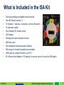
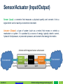
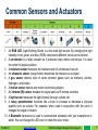
ISA Kit 1.0 User Manual May 2015 ® ISA Kit 1.0 Copyright © 2015 Intelligent Design Technology, LLC www.isakit.com www.isakit.com © 2015 Intelligent Design Technology LLC 1 ISA Kit ISA (Intelligent Sensor and Actuator)™ is an all-in-one educational kit for students and instructors in STEM (Science, Technology, Engineering and Mathematics) programs to learn and teach about sensors (inputs) and actuators (outputs) through interactive handson projects. The technology has been developed at the University of California, Irvine and Intelligent Design Technology, LLC (patent pending). It has been designed, developed, prototyped, and manufactured by Intelligent Design Technology, LLC. ISA Kit 1.0 www.isakit.com © 2015 Intelligent Design Technology LLC 2 Key Features of the ISA Kit - Easy to learn and use - No soldering or wiring is required - No pre-knowledge of coding is required (automatically generates C/C++ codes for Arduino-based microcontrollers) - Compact design to save space - No requirements for any additional tools or parts - Cost effective - Interactive tutorial - Integrates basic, intermediate, and advanced level projects - Appropriate for middle school, high school, and college students - Interactive communication with Windows OS and Android Apps - Made in the USA ISA Kit 1.0 www.isakit.com © 2015 Intelligent Design Technology LLC 3 What is Included in the ISA Kit • • • • • • • • • • • • One Arduino Mega compatible microcontroller One ISA Shield (version 3) 10 modules: 7 sensors, 2 actuators, and one Bluetooth 10 extension cables One infrared (IR) remote control LCD display Housing and sensor/actuator mounts 2GB flash drive ISA dashboard (windows-based software) ISA kit app for Android smartphone and tablets USB cable (to connect ISA kit to your PC) 9V to Barrel Jack Adapter + 9V battery (in case you are not using the USB cable) ISA Kit 1.0 www.isakit.com © 2015 Intelligent Design Technology LLC 4 Sensor/Actuator (Input/Output) Sensor (Input): a converter that measures a physical quantity and converts it into a signal which can be read by an electronic instrument. Actuator (Output): a type of system (such as a motor) that moves or controls a mechanism or system. It is operated by a source of energy, typically electric current, hydraulic fluid pressure, or pneumatic pressure, and converts that energy into motion. A device with integrated sensor and actuator Environment physical quantity ISA Kit 1.0 Input/ Sensor www.isakit.com Device Electric signal Electric signal Output/ Actuator Environment physical quantity © 2015 Intelligent Design Technology LLC 5 Common Sensors and Actuators 1. An RGB LED (Light-Emitting Diode) is a four-lead light source. By changing the light intensity of red, green, and blue (RGB) components different colors can be formed. 2. A servomotor is a rotary actuator so it produces rotary motion and torque. It is used for control of angular position. 3. A moisture sensor measures the moisture level of a media such as soil 4. An ultrasonic sensor (range finder) determines the distance to an object 5. A gas sensor detects level of some common gases such as methane, alcohol, Hydrogen, and smoke. 6. A motion sensor detects any motion and moving objects 7. An infrared (IR) sensor decodes the signal sent via IR remote controller. 8. A light sensor measures the light intensity through a photo cell. 9. A rotary potentiometer functions like a knob to increase or decrease a physical quantity such as volume. For example, when used in conjunction with the servo it changes the angle of rotation. 10. A Bluetooth transceiver is used to communicate wirelessly with your smartphone or tablet. You can change the LED color or rotate the servo motor. ISA Kit 1.0 www.isakit.com © 2015 Intelligent Design Technology LLC 6 ISA™ Sensors and Actuators 1 2 Actuators 10 3 Sensors 9 8 4 7 5 1 RGB LED 2 Servomotor 3 Moisture 4 Ultrasonic 5 Gas/Alcohol 6 Motion 7 Infrared (IR) 8 Light 9 Potentiometer 10 Bluetooth 6 ISA Kit 1.0 www.isakit.com © 2015 Intelligent Design Technology LLC 7 Unpacking the Box Push your fingers under the housing and lift it up Watch the video on YouTube ISA Kit 1.0 www.isakit.com © 2015 Intelligent Design Technology LLC 8 The ISA Kit Parts B A E 7 Accessories A Remote control 8 Actuators C 3 Sensors D ISA Kit 1.0 2 5 6 www.isakit.com 9 C 9V battery D Flash drive E LED 4 1 B USB cable 10 1 RGB LED 2 Servomotor 3 Moisture 4 Ultrasonic 5 Gas/Alcohol 6 Motion 7 Infrared (IR) 8 Light 9 Potentiometer 10 Bluetooth © 2015 Intelligent Design Technology LLC 9 Assemble Module #1 1 RGB LED: Insert the RGB LED in the LED holder and then insert it in module box #1 as shown below. The longest leg goes into the pin with no resistor connected resistors pin with no resistor connected ISA Kit 1.0 www.isakit.com © 2015 Intelligent Design Technology LLC 10 Assemble Module #2 2 Servomotor: Connect the wires of servomotor to module box #2 as shown in the picture (brown wire on the right, orange wire on the left). Then mount the servomotor. Make sure the propeller of the servomotor does not touch the wires while rotating; otherwise, the propeller may damage and cut the wires. ISA Kit 1.0 www.isakit.com © 2015 Intelligent Design Technology LLC 11 Assemble Modules #3 and #4 3 Moisture sensor: Connect the two parts of the moisture sensor and insert it in module box #3 as shown below. 4 Ultrasonic sensor: Insert the ultrasonic sensor in module box #4 as shown below. ISA Kit 1.0 www.isakit.com © 2015 Intelligent Design Technology LLC 12 Assemble Modules #5 and #6 5 Gas/Alcohol sensor: Insert the female to male extension header and then mount the gas sensor on module box #5 as shown below. 6 Motion sensor: Insert the motion sensor in module box #6 as shown below. ISA Kit 1.0 www.isakit.com © 2015 Intelligent Design Technology LLC 13 Assemble Modules #7 and #8 7 Infrared (IR) sensor: Insert the IR sensor in module box #7 as shown below. 8 Light sensor: Insert the light sensor in module box #8 as shown below. ISA Kit 1.0 www.isakit.com © 2015 Intelligent Design Technology LLC 14 Assemble Module #9 9 Potentiometer: Insert the rotary potentiometer in module box #9 as shown below. Instead of connecting the potentiometer directly to module box #9, you may use an extension cable in between. This way, it will be easier to rotate the knob on the potentiometer and signal noise will be reduced or eliminated. ISA Kit 1.0 www.isakit.com © 2015 Intelligent Design Technology LLC 15 Assemble Module #10 10 Bluetooth: Insert the Bluetooth transceiver in module box #10 as shown below. After connecting all the sensors and actuators, your ISA Kit should look like the following pictures. ISA Kit 1.0 www.isakit.com © 2015 Intelligent Design Technology LLC 16 Test the ISA Kit Sensors After connecting all the sensors and actuators, it is time to test them. 1- Make sure all the switches on the module boxes are in off position. 2- Turn on the RGB LED switch (module #1). ON OFF 3- Connect the 9V battery to the DC power connection in the ISA Kit 4- A couple of welcome messages will be displayed on the LCD and the RGB LED should blink red, green, and blue colors with fading effects. 5- Each module box has an on/off switch. In order to test any sensor you need to turn the switch on. Make sure all the other sensors and actuators are switched off. ISA Kit 1.0 www.isakit.com © 2015 Intelligent Design Technology LLC 17 Test the ISA Kit Sensors #3 and #4 3 Moisture sensor 1. Turn all the switches off. 2. Turn on the switch for module box #3. 3. Measure the moisture of the soil or a wet napkin/cloth. You may also measure the conductivity of your skin by holding the probe of the sensor in you hand and pressing it. 4. The moisture signal will be displayed on the LCD. moisture 4 Ultrasonic Sensor 1. 2. 3. 4. Turn all the switches off. Turn on the switch for module box #4. Move an object backward and forward in front of the ultrasonic sensor. The distance from object will be displayed on the LCD (the unit of measurement is in centimeter). ISA Kit 1.0 www.isakit.com Distance © 2015 Intelligent Design Technology LLC 18 Test the ISA Kit Sensors #5 and #6 5 Alcohol sensor Smoke Alcohol 1. Turn all the switches off. 2. Turn on the switch for module box #5. 3. Wait for a few seconds (~ 20 seconds) until the sensor calibrates itself. 4. Use smoke from a match or alcohol swab in front of the sensor. 5. The level of gas or alcohol will be displayed on the LCD. 6 Motion sensor 1. 2. 3. 4. Turn all the switches off. Turn on the switch for module box #4. Wait for a few seconds then move your hand. This sensor is very sensitive to motion detection so any motion in the vicinity of the sensor will be detected. One way to test the sensor is to use a Styrofoam or opaque plastic cup with a small hole in it. Cover the motion sensor with the cup. Any movement close to the hole will be detected. ISA Kit 1.0 www.isakit.com © 2015 Intelligent Design Technology LLC Small hole Motion 19 Test the ISA Kit Sensors #7 and #8 7 IR sensor 1. Turn all the switches off. 2. Turn on the switches for module box #1 (RGB LED) and #7 (IR). 3. Push the buttons on the IR remote control to change the color of RGB LED. 4. At the end, make sure to push the off button to turn the LED off. Infra Red 8 Light sensor 1. Turn all the switches off. 2. Turn on the switch for module box #8. 3. Change the light intensity using a flash light or by turning the room’s light on and off. 4. The level of light intensity will be displayed on the LCD. This is a number between 0 to 100. ISA Kit 1.0 www.isakit.com © 2015 Intelligent Design Technology LLC light 20 Test the ISA Kit Sensor #9 9 Potentiometer turn 1. 2. 3. 4. Turn all the switches off. Turn on the switch for module box #9. Turn the knob on the potentiometer. A number between 0 to 1023 will be displayed on the LCD. When you turn the knob clockwise (CW), the value increases and when you turn it counter clockwise (CCW), the value decreased. 5. To test the servomotor (actuator), turn on the switch for module box #2. The servomotor will follow the rotation of the potentiometer. Make sure the propeller of the servomotor does not touch the wires while rotating; otherwise, the propeller may damage and cut the wires. ISA Kit 1.0 www.isakit.com © 2015 Intelligent Design Technology LLC 21 Test the ISA Kit Bluetooth 10 Bluetooth 1. Turn all the switches off. 2. Turn on the switches for module boxes #1 (RGB LED) and #10 (Bluetooth). 3. Run ISA Kit Android app on your smartphone or tablet with Android mobile operating system (OS). 4. Find the ISA Bluetooth and connect to it. The instructions on how to connect to the ISA Bluetooth will follow in the next page. 5. Change the color of RGB LED from the app. 6. You may also control the servomotor and rotate the propeller. To do so, turn on the switch for module box #2 as well. ISA Kit 1.0 www.isakit.com © 2015 Intelligent Design Technology LLC 22 ISA Kit Application: Installing Download and install the ISA Kit Application (App) from Google Play: Method 1: Search for “isa kit” in Google Play. Keep the quotation marks when doing the search. Method 2: Scan the following QR code with your smart phone (Android). Then open the URL with Play Store. ISA Kit 1.0 www.isakit.com © 2015 Intelligent Design Technology LLC 23 ISA Kit Application: Pairing You need to pair your smartphone to the ISA Kit Bluetooth when connecting to it for the first time: 1. Turn on the Bluetooth on your phone or tablet. Turn on the Bluetooth (module #10) on your ISA Kit. The Bluetooth red LED should be blinking. 2. Scan (search) for Bluetooth devices. The ISA Kit Bluetooth name is “HC-06”. Select it. If asked for password, enter “1234” or “0000”. 3. If you do not see HC-06 in the list of nearby devices you may need to turn off the Bluetooth on your smartphone and ISA Kit and turn them back on then try again. ISA Kit 1.0 www.isakit.com © 2015 Intelligent Design Technology LLC 24 ISA Kit Application 1. Turn on the Bluetooth on your phone or tablet. Turn on the Bluetooth (module #10) on your ISA Kit. The Bluetooth red LED should be blinking. Then run the ISA Kit App. 2. Click on “Find Bluetooth” button on the App. 3. Select “HC-06”. If you do not see HC-06 you need to pair your device with the ISA Kit Bluetooth as instructed in the previous section. 2 1 ISA Kit 1.0 www.isakit.com 3 © 2015 Intelligent Design Technology LLC 25 ISA Kit Application (Cont’d) 4. When successfully connected, the button color will change to green and the Bluetooth LED will be solid (not blinking). 5. Now you can change the color of RGB LED (module #1) on your ISA Kit. Simply click on “ON” or “OFF” buttons for each color (Red, Green, and Blue). 6. You can rotate the propeller of the servomotor (module #2) by clicking on CW (clockwise) and CCW (counterclockwise) buttons. 5 4 6 ISA Kit 1.0 www.isakit.com © 2015 Intelligent Design Technology LLC 26 ISA Kit Application (Cont’d) 7. If you click on “Say the color” you can say the color name into the microphone. Main color names are: red, green, blue, yellow, cyan, magenta, purple, pink, orange, brown, black, and white. If you say “random” a random color will be generated. If you say “clockwise” or “counterclockwise” you can rotate the servomotor propeller. 8. If the color or command is not recognized, it will add “!?” in front of the color name. ISA Kit 1.0 www.isakit.com © 2015 Intelligent Design Technology LLC 27 Extension Cables Each sensor and actuator is connected to the ISA Shield through an extension cable. You can pull out the sensors and actuators from their compartments and move them according to the project requirements. ISA Kit 1.0 www.isakit.com © 2015 Intelligent Design Technology LLC 28 Extension Cables (Cont’d) 1 2 3 4 Push the sensor mount up then gently pull it out. ISA Kit 1.0 www.isakit.com © 2015 Intelligent Design Technology LLC 29 Extension Cables (Cont’d) Warning! Do not pull out the extension cables more than 6” (~15 cm). Do not pull out the Bluetooth (#10) and moisture sensor (#3) module boxes because their extension cables are too short. 1 2 10 9 3 4 8 5 7 6 ISA Kit 1.0 www.isakit.com © 2015 Intelligent Design Technology LLC 30 Software The ISA Kit comes with two software packages: 1. Arduino Integrated Development Environment (IDE) to develop C code and upload it to the Arduino board. 2. ISA Dashboard is a software package developed for the ISA Kit. It provides an interface between the user and sensors/actuators on the ISA Kit. It communicates with the ISA Shield that is mounted on an Arduino microcontroller. The ISA Dashboard gets the signals and displays them on the computer screen via a Graphical User Interface (GUI). It functions similar to an oscilloscope. The ISA Dashboard is compatible with Windows 7, 8, and 8.1 operating systems (OS). ISA Kit 1.0 www.isakit.com © 2015 Intelligent Design Technology LLC 31 Install Arduino IDE You can install the Arduino Integrated Development Environment (IDE) from the flash drive that comes with your ISA Kit. You may also download the latest version from the following link: http://arduino.cc/en/Main/Software. The following six steps depict the procedure to install the Arduino (IDE): 1 4 ISA Kit 1.0 www.isakit.com 2 5 © 2015 Intelligent Design Technology LLC 3 6 32 Arduino IDE After installing the Arduino IDE, you may run it and configure the settings. ToolsBoard Arduino Mega or Mega 2560 ISA Kit 1.0 www.isakit.com ToolsProcessor ATMega 2560 (Mega 2560) © 2015 Intelligent Design Technology LLC 33 Install ISA Dashboard Install the ISA Dashboard Toolbox by running ISAKit_Setup.exe. Install the ISA Dashboard after installing the Arduino IDE. We highly recommend to close all other applications while installing the ISA Dashboard. The following five steps depict the procedure to install the ISA Dashboard: ISA Kit 1.0 1 2 4 5 www.isakit.com © 2015 Intelligent Design Technology LLC 3 34 Run the ISA Dashboard 1. Connect the USB cable to the ISA Kit and the USB port of your computer. Make sure the 9V battery is NOT connected. 2. Turn on RGB LED (module #1) and servomotor (module#2). The run ISA dashboard by clicking on the ISAKit.exe shortcut ( ) on your desktop or from Windows Start menu. ISA Kit 1.0 www.isakit.com © 2015 Intelligent Design Technology LLC 35 ISA Dashboard 3 1 4 2 5 7 6 9 8 11 10 12 1 Animated arrow showing the signal received from sensor or the signal sent to an actuator. 2 Information of the current module being processed. 3 Command buttons: - Help: Opens the user manual. - Sample Data: Runs a sample data file - COM port menu: select the COM port (USB port) that is used for connecting the ISA Kit. ISA Kit 1.0 www.isakit.com © 2015 Intelligent Design Technology LLC 36 ISA Dashboard (Cont’d) 4 5 6 7 8 9 10 11 12 - Save log: When checked, the data log will be saved. - Start: Starts receiving data from the ISA Kit via USB cable. - Pause: Pauses receiving data from the ISA Kit. - Stop: Stops receiving data from the ISA Kit. Changes the scale of the y axis. Date received from the sensors. Date sent to the actuators. Temperature data (not available in the current version. Will be activated only if the temperature sensor is connected.) Plots data signals from the sensors versus time. A radial gauge. A bar gauge. Image of the selected module being processed. Opens the corresponding Arduino code (for basic, intermediate, and advanced projects). When you upload an Arduino code for basic or intermediate project, the Arduino code will not communicate with the ISA Dashboard. Only for the advanced projects the communication is enabled via the USB port. - Factory Reset: Opens the Arduino code that was originally uploaded on the ISA Kit when the package was delivered. ISA Kit 1.0 www.isakit.com © 2015 Intelligent Design Technology LLC 37 Module #3: Moisture Sensor 1. 2. 3. 4. Turn all the switches off. Turn on the switch for module box #3. An animated arrow will show signals are being received from the moisture sensor. Measure the moisture of the soil or a wet napkin/cloth. You may also measure the conductivity of your skin by holding the probe of the sensor in you hand and pressing it. 5. The data will be plotted versus time. 3 ISA Kit 1.0 www.isakit.com © 2015 Intelligent Design Technology LLC 38 Module #4: Ultrasonic Sensor 1. 2. 3. 4. 5. Turn all the switches off. Turn on the switch for module box #4. An animated arrow will show signals are being received from the ultrasonic sensor. Move an object backward and forward in front of the ultrasonic sensor. The data will be plotted versus time. 4 ISA Kit 1.0 www.isakit.com © 2015 Intelligent Design Technology LLC 39 Module #5: Gas/Alcohol Sensor 1. Turn all the switches off. 2. Turn on the switch for module box #5. 3. An animated arrow will show signals are being received from the gas/alcohol sensor. Wait for approximately 20 seconds while the sensor calibrates itself. 4. Use smoke from a match or alcohol swab in front of the sensor. 5. The data will be plotted versus time. OR 5 ISA Kit 1.0 www.isakit.com © 2015 Intelligent Design Technology LLC 40 Module #6: Motion Sensor 1. 2. 3. 4. 5. Turn all the switches off. Turn on the switch for module box #6. An animated arrow will show signals are being received from the motion sensor. Wait for a few seconds then move your hand. The motion detection data will be plotted versus time (0: no motion detected, 1: motion detected). 6. One way to test the sensor is to put a Styrofoam or opaque plastic cup with a small hole in it on top of the motion sensor. Any motion close to the hole will be detected. 6 ISA Kit 1.0 www.isakit.com © 2015 Intelligent Design Technology LLC 41 Module #7: Infrared (IR) Sensor 1. 2. 3. 4. 5. Turn all the switches off. Turn on the switches for module box #7 and #1 (RGB LED). An animated arrow will show signals are being received from the IR sensor. Push the buttons on the IR remote control. The LED color will change accordingly. The data will be plotted versus time. 7 ISA Kit 1.0 www.isakit.com © 2015 Intelligent Design Technology LLC 42 Module #8: Light Sensor 1. 2. 3. 4. 5. Turn all the switches off. Turn on the switch for module box #8. An animated arrow will show signals are being received from the light sensor. Change the light intensity using a flash light. The data will be plotted versus time. 8 ISA Kit 1.0 www.isakit.com © 2015 Intelligent Design Technology LLC 43 Module #9: Potentiometer 1. 2. 3. 4. 5. Turn all the switches off. Turn on the switch for module box #9. An animated arrow will show signals are being received from the potentiometer. Turn the knob on potentiometer. The data will be plotted versus time. Important: If you would like to control the servomotor (module #2) you should turn it on before running the ISA Dashboard. 9 ISA Kit 1.0 www.isakit.com © 2015 Intelligent Design Technology LLC 44 Module #10: Bluetooth 1. 2. 3. 4. 5. Turn all the switches off. Turn on the switch for module box #10. An animated arrow will show signals are being received from the Bluetooth. Run ISA App on your smart phone or tablet. The RGB color will change accordingly. Important: If you would like to control the servomotor (module #2) you should turn it on before running the ISA Dashboard. 10 ISA Kit 1.0 www.isakit.com © 2015 Intelligent Design Technology LLC 45 ISA Log File When you open the saved log file in Excel, you can plot the time history of the signals received. To do so, select the data then from “INSERT” tab click on “Insert Scatter (x,y)” and finally click on your desired plot type. 1 2 3 ISA Kit 1.0 www.isakit.com © 2015 Intelligent Design Technology LLC 46 ISA Projects B Basic projects (type 1): Single-Input Single-Output (SISO) 1 Sensor I Intermediate projects (type 2): Single-Input Multi-Output (SIMO) or Multi-Input SingleOutput (MISO) multi Sensors multi Actuators multi Sensors 1 Actuator Advanced projects (type 3): Multi-Input Multi-Output (MIMO) multi Actuators multi Sensors … www.isakit.com … multi Sensors ISA Kit 1.0 … multi Actuators … 1 Sensor A 1 Actuator multi Actuators © 2015 Intelligent Design Technology LLC 47 Sensors/Inputs and Actuators/Outputs Actuators (Outputs) 1 2 Bluetooth (In and Out) 10 3 9 8 4 Sensors (Inputs) ISA Kit 1.0 7 5 www.isakit.com 6 © 2015 Intelligent Design Technology LLC 48 SISO Projects ISA Kit ver 1.0 is ideal for Single Input, Single Output (SISO) projects. An example of a SISO project is a potentiometer (sensor/input) and a servo motor (actuator/output). Output/Actuator ISA Kit 1.0 www.isakit.com © 2015 Intelligent Design Technology LLC Input/Sensor 49 How to Run a SISO Project 1. 2. 3. 4. Connect the ISA Kit to your computer through USB cable Run the ISA Dashboard. Pick a sensor (input) or actuator (output) by clicking on its image. In the “Arduino Code” panel, select the difficulty level of the project: Basic, Intermediate, and Advanced. The Arduino code for the selected project will pop up in Arduino IDE. Make sure all the sensors/actuators are switched off. It is okay to leave RGB LED (module #1) on. Compile and upload the code by clicking on icon. 7 Use the sensor (input) and look at the actuator (output). 5 5. 6. 7. 8. 3 4 ISA Kit 1.0 www.isakit.com © 2015 Intelligent Design Technology LLC 50 Arduino Codes • • • • • When you compile and upload the code to Arduino it will overwrite the original file on the Arduino. When you upload an Arduino code for basic or intermediate project, the Arduino code will not communicate with the ISA Dashboard. Only for the advanced projects the communication is enabled via the USB port. So for basic and intermediate projects the sensor/actuator signals will not be plotted in ISA Dashboard. For basic projects, the LCD will be disabled. To see the sensor/actuator signals use “Serial Monitor” in Arduino IDE. After the Arduino code for a selected sensor/actuator is uploaded to the microcontroller, only the signal received/sent from/to that specific sensor/actuator will be monitored. So the signals from the rest of sensors/actuators will not be monitored. To get signals from all the sensors/actuators you need to click on “Factory Reset” button. “Factory Reset” button opens the Arduino code that was originally uploaded to the ISA Kit when the package was delivered. So to reset the configuration of the ISA Kit to its original status click on “Factory Reset” button and upload the Arduino code to the ISA Kit microcontroller. ISA Kit 1.0 www.isakit.com © 2015 Intelligent Design Technology LLC 51 Serial Monitor • • • “Serial Monitor” can be used to see the data transferred via USB port (COM or Serial port). After compiling the code to Arduino microcontroller, click on “Serial Monitor” to see the data. The baud rate value in “Serial Monitor” window should be the same as the baud rate used in the code. The default value is 9600. Serial Monitor ISA Kit 1.0 www.isakit.com © 2015 Intelligent Design Technology LLC 52 Arduino IDE Troubleshooting If an error message appears during uploading the code to Arduino, you may need to do one of the following actions: - Turn all the switches off (from module #1 to #10). - Check the USB port connection - Select the correct COM port number. This COM port number varies for different computers. - Unplug the ISA Kit from your computer and plug it back. - Reboot your system. ISA Kit 1.0 www.isakit.com © 2015 Intelligent Design Technology LLC 53 MIMO Projects You can do Multi-Input, Multi-Output (MIMO) projects with the ISA Kit ver 1.0. An example of a MIMO project is a four degree-of-freedom (DOF) tele-robotic arm. In this project, four potentiometers (sensors/inputs) and four servo motors (actuators/outputs) are used. Actuator 3 Actuator 4 Sensor 2 Sensor 3 Sensor 4 Actuator 2 4x 4 Actuators 4x 4 Sensors Actuator 1 ISA Kit 1.0 www.isakit.com Sensor 1 © 2015 Intelligent Design Technology LLC 54 ISA Shield ISA Shield is a Printed Circuit Board (PCB) interface between the Arduino microcontroller and sensors and actuators. ISA Shield 2 was designed for Arduino UNO and ISA Shield 3 is designed for Arduino Mega which comes with the ISA Kit 1.0. This shield is designed such that you can easily plug in your sensors and actuators. Arduino Mega ISA Shield 3 ISA Kit 1.0 www.isakit.com © 2015 Intelligent Design Technology LLC 55 ISA Shield 3 Servomotor Gas/alcohol Light Touch Potentiometer Motion Infrared (IR) Temperature/humidity Soft Potentiometer Pressure Buzzer Sound Bluetooth Ultrasonic (range) Moisture sensor Relay Find Line (Tracking) Joystick RGB LED Accelerometer LCD Pressure Resistor Solder a resistor that is appropriate for your pressure sensor. Sensors/actuators marked in red are part of the extended features for ISA Kit 1.0. 4-DOF tele-robotic arm ISA Kit 1.0 www.isakit.com © 2015 Intelligent Design Technology LLC 56 ISA Shield 3 (pins) +5V D Ground Digital pin #D A Analog pin #A C COM pin #C Analog + Power For intermediate and advanced projects Digital (PWM) + - R0T0 + 12 13 + - 32 0 + 4342 38 39 + - - + 9 1014 + 9 - 1011 + - 33 35 1112 1336 37 + - 5 6 7 8 + - 28 29 30 31 - + + - COM + 1 + 3 + 44 + +5 + 34 + - 40 + 41 + 15 +2 +8 +- 4 28 Digital ISA Kit 1.0 www.isakit.com © 2015 Intelligent Design Technology LLC 57 How to Access the ISA Shield The ISA Kit is designed such that you can disassemble and reassemble it back fast. In order to access the ISA Shield you need to follow these steps: 1. Remove the LCD lid and then unplug the LCD 2. Remove the top lid 3. Unplug all the wires from the sensor boxes 4. Push all the wires inside the middle wire compartment 5. Remove the middle wire compartment 3 4 5 1 2 ISA Kit 1.0 www.isakit.com © 2015 Intelligent Design Technology LLC 58 How to Access the ISA Shield (Cont’d) 6. This is how you see the ISA Shield 3 inside the ISA Kit. 7. A potentiometer is placed on the ISA Shield that can be used to change and adjust the LCD contrast. 8. An extra opening is considered on the housing for the projects that you need to use extra wires for additional sensors/actuators. To use it, push it gently from inside and the cap will pop out. 6 8 7 ISA Kit 1.0 www.isakit.com © 2015 Intelligent Design Technology LLC 59 Additional Sensors/Actuators The ISA Shield 3 is designed such that you can easily add different types of sensors and actuators and customize it based on the needs of your projects. Some of these extra sensors/actuators are temperature and humidity sensor, 3-axes accelerometer, touch sensor, pressure sensor, sound sensor, 2-D joystick, buzzer, and relay. ISA Kit 1.0 www.isakit.com © 2015 Intelligent Design Technology LLC 60 Add On: 4 DOF Telerobotic Arm In this MIMO project, four potentiometers (sensors/inputs) and four servo motors (actuators/outputs) are used. The connection is already available on the ISA Shied 3. ISA Kit 1.0 www.isakit.com © 2015 Intelligent Design Technology LLC 61 Add On: Remote Control Car Relay 9V Battery Ultrasonic Sensor IR Sensor ISA Shield ISA Kit 1.0 www.isakit.com © 2015 Intelligent Design Technology LLC 62 ISA Kit Projects Basic # of Sensors/Inputs # of Actuators/Outputs # of SISO Projects # of MIMO Projects 8 5 40 7,865 8 120 8,355,465 Pro (Extended) 15 ISA Kit 1.0 www.isakit.com © 2015 Intelligent Design Technology LLC 63 ISA Kit SISO Project 1 Pick a sensor (input) “#7:Potentiometer” in this example 2 Pick an actuator (output) “B:Servo” in this example 3 Click on the corresponding project name “B7” in this example 1 Sensor 3 Project Actuator 2 ISA Kit 1.0 www.isakit.com © 2015 Intelligent Design Technology LLC 64 Links ISA Kit website: http://www.isakit.com Intelligent Design Technology LLC: http://www.idesignt.com The Henry Samueli School of Engineering at the University of California, Irvine: http://www.eng.uci.edu/ Intelligent Structures and Systems Lab (ISSL): http://issl.eng.uci.edu/ Sensors and actuators of the ISA kit (YouTube): https://www.youtube.com/watch?v=GMSeic3EwSc Arduino: http://www.arduino.cc/ Email: [email protected] ISA Kit 1.0 www.isakit.com © 2015 Intelligent Design Technology LLC 65 TM ® ISA Kit 1.0 www.isakit.com Google play © 2015 Intelligent Design Technology LLC 66