1
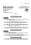
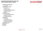
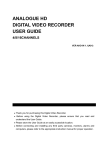
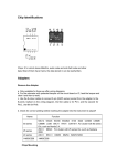
LART-CS08
Acceptance Test Plan – D005
Senior Design - Spring 2008
Lafayette College
5/4/2008
TABLE OF CONTENTS
T001: Rail Switch Control Test (R001) .............................................................................. 3
T002: Engine Power Control Test (R002) .......................................................................... 3
T003: Train Proximity Monitoring Test (R003) ................................................................. 4
Expandability and Adaptability (R004) .............................................................................. 5
T005: Control and Monitoring Speed Test (R005) ............................................................. 5
Applications Programming Interface (R006)...................................................................... 5
Maintenance User Interface (R007) .................................................................................... 5
T008: Demonstration Application (R008) .......................................................................... 6
Modifications of the CFE Layout (R009) ........................................................................... 7
T010: Power Input (R010) .................................................................................................. 7
GPR001: Documentation Test ............................................................................................ 7
GPR002: Environmental Requirement ............................................................................... 8
GPR003: EMI/EMC Requirement ...................................................................................... 8
GPR004: Hazmats ............................................................................................................. 10
GPR005: Safety and Good Practice .................................................................................. 11
GPR006: Reliability .......................................................................................................... 11
GPR007: Maintainability .................................................................................................. 12
GPR008: Sourcing Sustainability...................................................................................... 13
GPR009: Global Sustainability ......................................................................................... 14
GPR010: Ethics Report Test ............................................................................................. 14
GPR011: Project Demonstration....................................................................................... 15
GPR012: Final Disposal of Projects ................................................................................. 15
2
ACCEPTANCE TEST PLAN
T001: Rail Switch Control Test (R001)
This test will satisfy R001. Test by visual inspection and measurement to make
sure the software and interface electronics independently control each rail switch.
1. Turn the system on (if it is not already turned on).
2. Go the maintenance mode.
3. Repeat steps 4-7 for each of the 11 switches. Mark a pass or fail in the appropriate
column for each switch on the ATP Testing Fill out Form.
4. In maintenance mode, select the switch to be tested and change its direction once.
5. Visually inspect to see if the correct corresponding switch on the tracks moves.
6. Visually inspect that it went in the proper direction.
7. Visually inspect that the mechanical lever that throws the switch is all the way to
the side it was supposed to go to. (Switch can not be in an “unthrown” state.)
8. Throw the switch in the opposite direction.
9. Repeat steps 5-7.
Once these steps have been completed and all of the 11 switches are marked “Pass”,
this test (T001) will be considered completely passed. Mark “Overall T001” as a
“Pass”.
T002: Engine Power Control Test (R002)
This test will satisfy R002. Test by visual inspection to make sure that the
software and interface electronics independently control each track segment. Each
segment must be independently programmable in terms of train direction and speed. This
will test each rail to make sure the train can go in two directions as well as test to make
sure the speed control is variable from stop to a maximum speed with a minimum of 16
speed levels.
1. Turn the system on (if it is not already turned on).
2. Go to the maintenance mode.
3. Connect the top right most track segment at Metzgar Terminal to an oscilloscope
(see step 7 for how to do this), set the direction to go left and the speed to 15.
4. Inspect the voltage of the track segment on the oscilloscope. It should be between
+17V and +20V (Maximum measurement on the oscilloscope).
5. Place a screwdriver across the rails for 5 seconds and remove it.
6. Verify the voltage on the oscilloscope returns to normal when the screw driver is
removed. If it has not changed, mark a Pass on the fill out form for the “Shorted
Rails Test”.
7. For each and every track segment on the track layout. (Start with the track
segments at 3rd St.). Connect each segment to an oscilloscope by connecting the
black connector of the probe to the system common ground and the scope probe
to the top rail of the track segment. Show the Duty Cycle and Maximum
measurement on the scope.
3
8. Set the direction of the track segment to left and the speed to 0.
9. Inspect the oscilloscope for the PWM signal duty cycle and the voltage of the rail.
The duty cycle should be at 11% (+/-1.5%) and the voltage should read between
+17V to +20V. Mark the ATP Fill out Form appropriately for each track segment.
10. Once all track segments have passed for Speed 0, place a train on the top-right rail
at Metzgar Terminal.
11. Connect this track segment to an oscilloscope by connecting the black connector
of the probe to the system common ground and the scope probe to the top rail of
the track segment. Show the Duty Cycle measurement on the scope.
12. Set the direction of the track segment to left and the speed to Speed 2.
13. The train should run until the end of that track segment and stop.
14. Check the oscilloscope to see that the duty cycle is at 23% (+/-1.5%). Mark the
Fill out form for this track segment.
15. Continue changing the speeds of all of the top rails one by one from right to left to
Speed 2 checking to make sure the train stops at the end of each track segment.
Mark the Fill out form for each top track segment.
16. When the train is at the top-left most rail at 3rd St., change the direction of all the
top rails to go right and make all of the top rails at Speed 8 (from right to left so
the train runs smoothly.)
17. Check the oscilloscope to see that the duty cycle is at 59% (+/-1.5%). Mark the
Fill out form for each top track segment.
18. When the train has returned to the top-right most rail at Metzgar, change the
direction of all of the top rails to go left and make all of the top rails at Speed 15
(from left to right so that the train runs smoothly.)
19. Check the oscilloscope to see that the duty cycle is at 99% (+/-1.5%). Mark the
Fill out form for each top track segment.
20. Repeat steps 11-19 for all of the middle and bottom rails.
21. If all of the above steps have been marked Pass, then the following cases for the
rails can be marked a Pass: the ++ and - - option. This was also verified in
subsystem testing.
Once these steps have been completed and all of the rails’ directions and speeds are
marked “Pass”, this test (T002) will be considered completely passed. Mark “Overall
T002” as a “Pass”.
T003: Train Proximity Monitoring Test (R003)
This test will satisfy R003. Make sure that test T002 has passed before attempting
to complete this test. Test by visual inspection to make sure that the software and
interface electronics allow the independent programmed monitoring of all train proximity
sensors in the track layout.
1. Turn the system on (if it is not already turned on).
2. Go to maintenance mode.
3. Place a train on the top-right most rail at Metzgar Terminal.
4
4. Starting with the left most station (3rd St.) and ending at Metzgar Terminal. Set all
of the top rail segments to the left direction and set them at Speed 2 (Only if
successful T002).
5. Once the train passes over each sensor on the top row of rails, note whether it was
monitored properly by the computer. If the sensor is working properly mark
“Pass” next to the sensor being tested on the ATP Fill out Form.
6. Place a train on the middle-left most rail at Metzgar Terminal.
7. Repeat steps 4 and 5 for the middle rail segments.
8. Place a train on the bottom-left most rail at Metzgar Terminal.
9. Repeat steps 4 and 5 for the bottom rail segments.
Once these steps have been completed and all of the sensors are marked “Pass”, this
test (T003) will be considered completely passed. Mark “Overall T003” as a “Pass”.
Expandability and Adaptability (R004)
This test satisfies R004. Because of a written XML document and Maintenance
Manual which will be submitted May 9th. This makes sure that the system can support
multiple trams operating simultaneously without any extensive recompilation of the
software or hardware redesign. Because of the completion of these two documents,
nothing needs to be marked on the Fill out Form.
T005: Control and Monitoring Speed Test (R005)
This test will satisfy R005. Test by measurement to make sure the delay
throughout the hardware and over the cables does not adversely affect the performance of
our control system.
1. Turn the system on (if it is not already turned on).
2. At Station 3 (Skillman Station), connect the sensor right before switch 4 to
Channel 1 on an oscilloscope. Connect the black lead to the common ground and
the scope probe to the sensor. Set the oscilloscope to trigger channel 1.
3. Connect switch 4 to Channel 2 on the oscilloscope.
4. Run mini program for this test.
5. Once the switch has switched measure the time between the sensor activity and
the switching on the oscilloscope. Verify that this distance is less than 100m
seconds (as per the Timing Analysis done for CDR). If so, mark T005 as a Pass
on the fill out form.
Applications Programming Interface (R006)
This requirement was met by providing an API. See QA Audit for test results.
Maintenance User Interface (R007)
This requirement is met by T001, T002 and T003. It was also tested in subsystem
testing.
5
T008: Demonstration Application (R008)
This test will satisfy R008. The LART-CS08 shall provide a fully documented,
user friendly, easy to use, Demonstration Application. A fully documented easy to follow
user manual should be in place. This requirement will be tested by having a non-technical
user successfully run an automatic demonstration of the capabilities of the LART-CS08
and CFE track layout. This user’s name is noted on the Fill out form (ATR).
Simultaneous automatic motion of multiple trains and informative end user train arrival
displays should be demonstrated. A determined schedule for the trains will be
predetermined. The trains will be observed at different specified times and compared to
where they should be to determine if the demonstration application has passed the test.
The schedule will involve two local trains and one express train.
1.
2.
3.
4.
5.
Turn on Computer.
On desktop, double click folder marker “spr08”.
Double click on folder marked “eclipse”.
Double click on “eclipse” program.
On left hand side of the screen, click “Controller”, then click “src”, then click
“Default Package”.
6. Double click “Maintenance Interface”.
7. Go to the Run menu at the top and click Run.
8. Place three trains on the track layout. One on the top rail at Metzger Terminal,
one at the top rail at 3rd Street Station and the other at the bottom rail at 3rd Street
Station.
9. Reset all of the stations (press the red button on each of the five station boards).
10. After placing each of the trains on the track move each on of them over the sensor
they are closest to making sure the computer has recognized the trains.
11. Check Station 1 for the top left and middle left sensors to be activated and on
Station 5 for the top right sensor to be activated.
12. Click on File > Demonstration Mode.
13. Click on GO to make the trains move on the tracks based on the schedule of the
program. This will operate 2 local trains with one express train.
14. Observe the movement of the trains so that they match the schedule shown below
at each of the 13 stops. (The dark line on the schedule represents the express train
which starts on the middle track at the 3rd St. station, the lighter line on the
schedule represents one of the local trains which starts on the top track at the 3rd
St. station and the dotted line on the schedule represents the other local train
which starts on the top track at Metzgar Terminal.
6
Once these steps have been completed and all of the steps “Pass”, this test (T008) will be
considered completely passed. Mark “Overall T008” as a “Pass”.
Modifications of the CFE Layout (R009)
We didn’t do any modifications to the CFE Layout, therefore this requirement is
met.
T010: Power Input (R010)
This test will satisfy R010. The LART-CS08 shall operate on the standard
120VAC, 60Hz power available from a single outlet in AEC room 419. A multi-outlet
power strip and extension cords will be used. All other voltages will be generated by the
ac-dc converter. A visual inspection of the LART-CS08 will verify that this requirement
has been made.
1. Visually inspect the LART-CS08, only one single power outlet should be used
GPR001: Documentation Test
We will test to make sure we have met this general project requirement by visual
inspection and analysis. We will test to make sure that all of our project documents are
accumulated in electronic form, uploaded to our project website and properly indexed.
We will make sure all final system level documentation has been created and that all of
the schematics for our sub systems follow the proper drawing format. All software will
be inspected to make sure they are in the proper format. Also, we will make sure our
user’s manual and maintenance manual follow the appropriate requirements.
1. Go to the project website.
2. Verify that all of the deliverables (D001, D002, etc.) are posted on the website
and are in PDF format except for the Maintenance Manual which is to be
submitted May 9th. Please refer to the System Requirements packet from the
beginning of the semester for the table of deliverables.
Once all of the documents have been posted on the website and all of the submissions
have all been marked “Pass”, this test (GPR001) will be considered completely
passed. Mark “Overall GPR001” as a “Pass”.
7
GPR002: Environmental Requirement
This requirement was satisfied partially by analysis. It will also be satisfied by
measurement. We made sure that all of the components that were purchased met the
specifications in this requirement. All projects demonstrate reliable and normal functional
operation in ambient lab temperatures of 15 °C to 30 °C, 10% to 80% RH, noncondensing. The overall system tolerates a storage environment of 0 °C to +60 °C, 5% to
95% RH, non-condensing. Designs use electronic components rated for commercial
temperature range (0 – 70 °C) or better.
1. Turn the system on (if it is not already on).
2. Make sure that the PCB Board enclosures are on top of all of the boxes at each of
the stations.
3. Run the Demo mode for a minute and then click Stop.
4. For each station remove the top of the box and quickly perform step 5.
5. Using a laser thermometer check the temperature on the LM317 components and
the LM200 component on each of the five boards. Their temperature should be
below 110°C.
6. Mark a Pass on the Fill out Form for each board if all of the LM317 and LM200
components on that board are operating under the temperature restriction.
Otherwise, note the part number labeled on the board and write down the
temperature read from the thermometer in the Measurements/ Comments column.
Once these steps have all been marked “Pass”, this test (GPR002) will be considered
completely passed. Mark “Overall GPR002” as a “Pass”.
GPR003: EMI/EMC Requirement
This requirement was satisfied by system analysis. We made sure any
unintentional electromagnetic radiation emitted from our system met US CFR Title 47
Part 15 subpart B regulations for Class A digital equipment. This was tested by analyzing
the documentation of our parts and making sure they follow the specifications in the CFR
document.
EMI/EMC Analysis
The FCC places the following limits on electromagnetic conduction emissions
from section 15.107.
8
The FCC places the following limits on electromagnetic radiation emissions from
section 15.109.
A number of product types are exempt from having to comply with all technical
requirements of Part 15 except for the general rule that they may not cause interference.
Section 15.103 exempts those digital devices that:
1. are used solely in any transportation vehicle such as a car or an airplane;
2. are used solely as an electronic control or power system by a public utility or in an
industrial plant;
3. are used solely as industrial, commercial, or medical test equipment;
4. are used solely in a domestic or commercial appliance;
5. are used as specialized medical devices under the direction or supervision of a licensed
healthcare practitioner;
6. have a power consumption of 6 nW or less; or
7. use or generate a frequency less than 1.705 MHz and are never connected to the AC
line.
The final exempt class of device is:
9
9. a joystick controller, mouse, or similar device that is used with a digital device but
itself contains nondigital circuitry. Such devices are, for these purposes, regarded as
passive add-ons.
Our system is exempt under 2 because it is used as an electronic control by a public
utility (rail transport system).
The general requirements of Section 15.5 still apply. Our design satisfies these
requirements.
Section 15.5 General conditions of operation.
(a) Persons operating intentional or unintentional radiators shall not be deemed to have
any vested or recognizable right to continued use of any given frequency by virtue of
prior registration or certification of equipment, or, for power line carrier systems, on the
basis of prior notification of use pursuant to Section 90.63(g) of this chapter.
(b) Operation of an intentional, unintentional, or incidental radiator is subject to the
conditions that no harmful interference is caused and that interference must be accepted
that may be caused by the operation of an authorized radio station, by another intentional
or unintentional radiator, by industrial, scientific and medical (ISM) equipment, or by an
incidental radiator.
(c) The operator of a radio frequency device shall be required to cease operating the
device upon notification by a Commission representative that the device is causing
harmful interference. Operation shall not resume until the condition causing the harmful
interference has been corrected.
(d) Intentional radiators that produce Class B emissions (damped wave) are prohibited.
GPR004: Hazmats
This requirement was satisfied by analysis. We did not use any hazardous
materials in the design of our system. All of the materials used meet the 2002/95/EC
RoHS directives. We also used only lead-free solder. We will also make sure that when it
comes time to discard any components, that they be discarded according to the Lafayette
College Chemical Hygiene plan.
Hazmat Analysis
We did not use hazardous materials in our design. All parts of our system are
RoHS compliant as displayed in the BOM. The solder that we used was Lead-free. Any
portion of the design or prototype that needs to be discarded will be discarded according
to the Lafayette College Chemical Hygiene plan or the 2002/96/EC WEEE directive,
either by ecological disposal or by reuse/refurbishment of the collected waste. The
2002/96/EC WEEE directive says,
10
As a minimum the following substances, preparations and components
have to be removed from any separately collected WEEE:
- printed circuit boards of mobile phones generally, and of other devices if
the surface of the printed circuit board is greater than 10 square
centimetres, …
- external electric cables, …
- electrolyte capacitors containing substances of concern (height > 25
mm, diameter > 25 mm or proportionately similar volume)
These three are parts of our system. We will have to remove separately our
printed circuit boards, our external eclectic cables, and our electrolyte capacitor for
proper disposal.
GPR005: Safety and Good Practice
This requirement was satisfied throughout the course of the project. We have
constructed all of our electronic components with good industry practice to enhance
reliability and maintainability. We have also made sure that the project activities adhered
to the general Lafayette College safety policy and ECE Laboratory safety rules. We have
inspected all power supplies to make sure their outputs do not exceed 30 Volts.
GPR006: Reliability
This requirement was satisfied by the reliability analysis.
Reliability Analysis
The Mean Time Between Failure (MTFB) for each part was taken from their
manufacturers’ website. The MTFB for the PIC circuit was found by dividing by 4 the
MTFB for each PIC, since they are in series. Furthermore, PC – PIC – PCB are all in
series, their MTFB was found according to the following formula:
MTFBt = [(1/MTFB1) + (1/MTFB2) + … + (1/MTFBn)]^-1
The MTFB of the PCB was found by applying the same formula for 4 critical
parts of the PCB board which are in series. It was unnecessary to include all the parts, as
the MTFB of the computer (Intel Pentium 4) dominates the overall MTFB. The DB9
connector was referenced from a USB-DB9 converter MTBF, since it was the closest
thing to our cables for which no reliability data seemed to be available, probably because
they are so reliable.
MTBF
60%
Fan
Power
Supply
PC (hrs)
4xPICs
(hrs)
PCB (hrs)
Total (hrs)
6.20E+04
3.03E+05
1.180E+05
6.250E+07
1.524E+07
5.283E+03
9-bit Reg
1.072E+08
LM-317
7.371E+08
DB9
1.940E+07
@
PCB
H-Bridge
2.941E+08
11
Furthermore, we can express the Probability of no failures (Probability of success)
P(s) = e^(-t/MTFB). If we graph this vs. time, we get the following graph:
Note that at the required reliability time of 100 hours, we are 99.91% sure that
this system will not fail. This passes the reliability requirement.
GPR007: Maintainability
At minimum, the system MTTR (Mean Time To Repair) should be less than 1
week. In order to provide for this all components must be able to be obtained from at
least two suppliers. A fully documented API would also help in repairing the system
incase some code or hardware got corrupted. Fully documented sub-system diagrams
would also help reduce the MTTR making it easier to order replacements or fix a
particular sub-system. For minor complications the user’s manual should be a sufficient
resource. This requirement has been analyzed in the system analysis.
Mean Time to Repair (MTTR) for the overall system includes the following:
•
•
Time spent troubleshooting the error
Time spent resolving the error
We can conclude that if we can find which sub-system is causing the error by
troubleshooting the system, and then we can reduce the overall MTTR to the total of the
time spent resolving the error. The worst case MTTR then is the sum of this
troubleshooting period and the time it takes to repair the sub-system that takes the longest
to repair.
The longest troubleshoot time is 3 days, each day to troubleshoot one sub-system,
until we find that the last system we checked is the faulty one.
Time to repair the UI system is 2days, as the possible problems are most likely caused
by wrong XML files, or faulty Application Programs.
12
Time to repair the Networking system is 2 days, 1 day to find which sub-system(s)
are faulty (RS-232, Sensor Polling, Switch & Rail Control) and 1 day to fix the problem
itself.
Time to repair the Low-Level system is 3 days, 2 days to find the source of the
problem, as there are as many as 100 parts involved, and 1 day to fix the problem.
Thus, the overall system MTTR is 3days troubleshooting+3days max to fix the faulty
sub-system = 6days, leaving us 1 spare day.
A list of spare parts is not crucial to maintain as all the components can be obtained
within a max of 5 days shipping. Overnight delivery ensures quick replacements.
See below for a troubleshooting flowchart which refers to the LED’s on the printed
circuit boards.
GPR008: Sourcing Sustainability
All production designs must be built from components and subassemblies that
have a sustainable source of supply over the system lifetime. This will be satisfied by
ensuring each component is available from at least two suppliers. Each component in the
BOM lists 2 suppliers available on the website satisfying this requirement. Each
13
component from the BOM should be a readily available component which has been in
existence for the past 5 years indicating that it will be around for number of years.
GPR009: Global Sustainability
All production designs should be synthesized with consideration to techniques
that maximize global sustainability. Also, all of the components used are RoHS
compliant in order to cause minimal harm to the environment.
1. Check that each component is RoHS compliant.
2. See Global Sustainability Analysis below.
Global Sustainability Analysis
In order to help global sustainability, the project should not be contributing to the
death of the ecosystem considerably so it may go unnoticed as bigger sources pollute and
destroy the world. In fact in perspective we seem relatively eco-friendly.
The LART system uses electricity and releases no emissions which considerably
reduces its negative effects on the environment. Furthermore, it reduces people’s need to
travel by individual cars, and promotes commuting, which also greatly reduces the
negative effects on the environment of the people around its vicinity. Also, all the
stations that the train passes through have recycle bins, which give people an incentive to
throw away their trash into appropriate trash bins thereby improving overall recycling
efforts.
GPR010: Ethics Report Test
This was addressed by a fully documented Ethics Report. This was submitted
PDR. It resulted in the following extra requirements.
ER001: Trams must not crash
Software includes a failsafe mode which will be communicated over the RS-232.
This requirement will be tested by running the demo mode and ensuring that a collision
doesn't occur.
ER002: The trains must not accelerate or decelerate too abruptly
Train acceleration and deceleration will not cause illness to passengers. Train
acceleration and deceleration will be controlled by the master PIC. This will be tested by
measurement and visual inspection. The ramping test will be carried out by observing the
PWM pulse on an oscilloscope.
1. Turn the system on (if it is not already turned on).
2. Place three trains on the track layout: one on the top rail at Metzger Terminal,
one at the top rail at 3rd Street Station and the other at the bottom rail at 3rd Street
Station.
3. Go to demo mode and click Go. (Only if successful T008.)
4. Visually inspect the trains when they arrive and depart from the stations. Note
whether or not they slow down and speed up appropriately.
14
5. Stop the demo mode.
6. To do a measurement, go to maintenance mode.
7. Connect the oscilloscope to any rail segment without a train on it. (See T002
for instructions on how to connect the oscilloscope going in the left direction.) Set
it up to measure Duty Cycle.
8. Select that rail segment in maintenance mode, set the direction to left and set
the speed to Speed 10. (Only after successful T002).
9. While another tester watches the duty cycle on the oscilloscope, change the
speed to Stop.
10. The duty cycle should decrease by 1% (+/- 0.5%) until it reads 9% (+/- 1.5%).
If this is true, mark a Pass on the Fill out Form for deceleration.
11. While another tester watches the duty cycle on the oscilloscope, change the
speed to Speed 10.
12. The duty cycle should increase by 1% (+/- 0.5%) until it reads 71% (+/1.5%). If this is true, mark a Pass on the Fill out Form for acceleration.
Once these steps have been completed and all are marked “Pass”, this test (GPR010)
will be considered completely passed. Mark “Overall GPR010” as a “Pass”.
GPR011: Project Demonstration
A completed project must be demonstrated for review by ECE faculty. This will
be verified visually ensuring that the trams are controlled and monitored as per project
requirements.
1. A short presentation of the system design
2. Demonstration of the system in Maintenance mode.
3. Demonstration of the system in Demo mode with three trains. Two local and
one express.
GPR012: Final Disposal of Projects
Some parts of the project will be stored for future work, placed on display, or
discarded. Separate parts have been properly labeled so their association with the stored
project is obvious. Any hidden portions are enclosed in a sealed container, locked cabinet
or secured room. This cabinet, as of now, is in the projects lab. We will move all spare
parts and hidden portions to the Digital Circuits lab after the final presentation. This will
be verified visually by checking off a cleanup checklist. The list includes:
1.
2.
3.
4.
5.
6.
7.
Trains
Station Boards
Extra Components (spare parts)
Master PIC
Master PC
Test equipment and tools returned to their proper places
Lab benches and tables cleaned
15