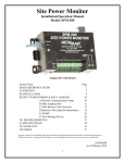
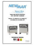
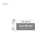
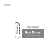
1
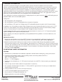
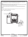
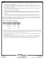
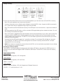
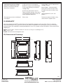
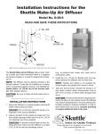
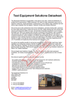
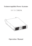
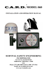
Multi-Timer Fuse Distribution System User’s Manual Model: MT-FD 6 Section Page Product Overview............................................. 1 I) General Information......................................... 2 Optional Accessories.................................... 2 II) Important Safety Information........................... 2 III) Installation....................................................... 3 A) Materials Provided.................................. 3 B) Location.................................................... 3 C) Mounting................................................. 3 D) System Expansion - Parallel Units........... 3 IV) Wiring Instructions & Diagrams........................ 3 V) Load Group Power Activation Programming.. 6 Programming Overview.............................. 6 Programming the Load Group Relays......... 6 Re-Setting to Factory Defaults...................... 9 Default Settings............................................ 9 VI) LVD Verification Note....................................... 10 VII) Operation......................................................... 10 VIII) Specifications.................................................... 10 IX) Troubleshooting............................................... 11 X) Warranty.......................................................... 12 XI) Dimensional Drawing....................................... 12 Manual Part #: M-MTFD6 As of November 2013 P.O. Box 1306 Newport Beach California 92663 Phone: 714-751-0488 Fax: 714-957-1621 E-Mail: [email protected] Product Overview Ignition Sense (+) Terminals, 1/4” Male Fast-On ATC/ATO Fuse Circuit ID # 20 Amp Max. Fuse Ok LED (Green) +12V Load Terminals Ground Load Terminals •REPLACE PROTECTIVE COVER AFTER INSTALLATION/SERVICE Tel: (714) 751-0488 E-mail: [email protected] INPUT POWER Dip Switch Modules Set Power “ Activation Parameters Per Load Group: •Powered Only With Ignition •Timed Disconnect POWER MODE LOAD GROUP 2 3 4 •INSTALL 100A FUSE/CIRCUIT BREAKER ON + INPUT Battery Ground/ Parallel Bus Tie Point LOAD GROUP 1 1 2 UP, DOWN LOAD GROUP 3 SWITCH PROGRAM POSITION LOAD GROUP 1 LOAD GROUP 2 +12V DC Battery In/ Parallel Bus Tie Point •12V DC, NEG. GROUND, 100 AMPS MAX (-) POWER GROUND LOAD GROUP 3 5 6 MT-FD 6 IGN INPUT (+) (-) POWER Multi-Timer Fuse Distribution System CAUTION: 20 AMPS MAX ATC/ATO FUSE (+) LOADS Silk Screen: MT-FD6 Status LED (Red) P/N: SS15733-0 Rev. 000 • Programming Status November 13, 2013 Battery Input OK (Green) Master Low Voltage Disconnect Disables Power to All Loads When Input Voltage is Less Than 10.5V DC • Ignition OFF • Over Voltage Shutdown • Under Voltage Shutdown •Always On with Adjustable Load Group LVD •Always On, No Load Group LVD 1 P.O. Box 1306 Newport Beach California 92663 Phone: 714-751-0488 Fax: 714-957-1621 E-Mail: [email protected] I) GENERAL INFORMATION The MT-FD 6 provides emergency and public safety vehicle electronics installers with a convenient, efficient, safe and dependable method for adding distribution, circuit protection, timer and power control to communication electronics and electrical devices. Its compact size allows installation under consoles and in interior compartments (not intended for installation in engine compartment). As a standalone power distribution system, there is no interference with the vehicles factory installed wire harness; the MT-FD 6 wires directly to the vehicle battery. Each of the 6 circuits are individually fused (ATO /ATC type) and wired to power-on/fuse fail indicator LED’s which simplifies circuit troubleshooting. The 6 distribution circuits are configured into 3 load groups of two, power control to each individually group is programmable via 4 user selectable options: Always ON • ON with Ignition, OFF with Ignition • ON with Ignition, Timed OFF (adjustable time interval) with Ignition • ON with Battery, OFF upon Low Voltage sense LVD (adjustable disconnect point) with 20 second delay In addition, the unit contains a master Under Voltage sense circuit that de-activates the whole unit @ 10.5V to save the vehicle battery from extreme discharge, and automatically reconnects when battery charge recovers. Contact factory for custom Master Under Voltage Shutdown threshold. A Hight Voltage Shutdown circuit is also built-in that de-activates the whole unit @ 16.0V protecting loads against damage due to malfunctioning alternators. System capacity can easily be expanded by wiring additional PDS in parallel (18 circuits maximum), see options below. Optional Accessories 1) Parallel Bus Bar Kit allows up to three MT-FD 6’s inputs to be paralleled for additional circuits. One kit required for two MT-FD 6s, two kits for three MT-FD 6s. Order model PBK, part number 390-5723-0. 2) Parallel Load Terminal Kit allows two output circuits in the same Load Group to be paralled for loads that exceed the single circuit, 20 amp capacity, providing up to a 32 amp circuit. One kit includes one fork terminal with hardware to allow one heavy cable to land on to two +12V load terminals of the same Load Group. Load ground cable connects to single #6 screw located on the Battery Ground bar. Order model PTK, part number 390-5725-0. II) IMPORTANT SAFETY INFORMATION CAUTION: • Read and fully understand the installation/operation manual before making any wiring connections. • To avoid reverse polarity confirm correct polarity before connecting cables to MT-FD 6. Stud ends are color coded with polarity: RED = +12 VDC/Positive BLACK = - 12 VDC/Negative • Install fuse/circuit breaker on +12 VDC power feed/input wire to MT-FD 6. Size to match your loads and wire size. • Connect high current feeder cables to the provided ¼” studs only. • Run separate, dedicated ground cable (- 12 VDC) to MT-FD 6 ground stud. Do not rely on chassis frame for grounding connections. • 20 Amp maximum fuse. Use ATC/ATO style fuses only. • 12 VDC nominal negative ground systems only • Do not exceed 100 Amps total load per unit • Replace protective cover after installation P.O. Box 1306 Newport Beach California 92663 2 Phone: 714-751-0488 Fax: 714-957-1621 E-Mail: [email protected] III) INSTALLATION IMPORTANT NOTICE: If not using the factory default programming (see page 9, Setting to Factory Defaults), we recommend first programming the MT-FD 6 on a bench for convenience before installation. See page 6, Section V - Load Group Power Activation Programming. A) Materials Provided Qty. Description 1 Installation/Operation Manual (M-MTFD6) 1 MT-FD 6 Power Distribution System 1 Protective plastic cover 1 7” jumper wire with 1/4” female fast-on and ring terminal - use to jumper power from input bus to IGN. terminal when programming unit on bench 2 Cover attachment screws, nylon, black 4 Sheet metal mounting screws, #10 x 1/2”, self tapping, Phillips Pan Head, S.S. 1 ¼” fast on terminal, 90°, insulated (Ignition sense) 1 Programming data card and holder to record settings entered 1 Rubber boot (+ battery/power feed) Note: Fuses not provided B) Location Select position in the interior of the vehicle where there will be ample space for wire routing and access to the fuses, and where it will not be subjected to extreme heat, moisture – liquids, or impact by tools or other items stored in the compartment. C) Mounting Always attach to the vehicle metal frame so that it cannot come off in an accident or heavy breaking situations. Use provided self-tapping sheet metal screws (4 ea). Mount with fuse side up. Do not mount under the hood in engine compartment. D) System Expansion - Parallel Units Circuit capacity can be expanded by wiring a second and third MT-FD 6 unit to the first (see Figure 2) each additional MT-FD 6 provides 6 additional load circuits (18 circuits maximum). IV) Wiring Instructions & Diagrams Refer to Figure 1 wiring diagram for a single unit wiring & Figure 2 for multiple unit wiring. Refer to Tables 1, 2 & 3 on page 5 for recommended wire size for input power feed, load wiring & multiple unit input power feed. Battery CAUTION: Install a fuse or circuit breaker on the positive (+) battery power feed wire as close to the battery as possible in order to protect the input power feed wires. Size fuse or circuit breaker 125-150% of the maximum load current. For single MT-FD 6 installations, see Table 1 “Recommended Input Power Feed Wire Size”. Identify the total amperage of all loads to be connected to MT-FD 6 and then identify recommended wire size based on the cable distance between the vehicle battery and the MT-FD 6 mounting location. Note: For any wire runs that fall between wire length shown in tables on page 5, use the longer wire run to determine wire size. Slide provided rubber boot over positive (+) battery feed cable before crimping 1/4” stud. For multiple MT-FD 6 installations, refer to Table 3 “Recommended Input Power Feed Wire Size for Multiple Units” for battery wire size. P.O. Box 1306 Newport Beach California 92663 3 Phone: 714-751-0488 Fax: 714-957-1621 E-Mail: [email protected] Use 1/4” crimp ring terminals to make the wire connection to the +12V and ground input studs on single MT-FD 6 installations and 5/16” crimp ring terminals (Parallel Bus Bar Kit, model PBK) for multiple MT-FD 6 installations. Slide rubber boot over positive (+) stud after securing cable to stud. Loads CAUTION: Maximum load group circuit fuse value is 20 amps. Fuses should be sized to 125-150% of the load current to prevent nuisance fuse blowing with appropriate size wire Refer to Table 2, “Recommended Circuit Load Wire Size” for recommended wire size for each load. Use ring or fork crimp terminals to make the wire connections to the +12V load terminal block and ground load terminals. Ignition A wire size of 18 AWG or greater should be used to make the ignition input connection to the MT-FD 6. An insulated,16/14 AWG, 1/4” female fast-on (90˚) is provided. Figure 1: Single Unit Wiring Drawing FUSE OR CIRCUIT BREAKER SIZED TO YOUR LOAD, NO FUSE LARGER OR CIRCUIT BREAKER THAN 100 AMP _ +12 VOLT BATTERY +12V IGNITION SIGNAL ON>5V OFF<5V + ( ) (+) (-) TO TYPICAL LOAD 10 20 20 10 20 20 20 AMPS MAX PER CIRCUIT Optional Parallel Load Terminal Kit provides single, high power 32 amp circuit by paralleling output of two circuits P/N: 390-5725-0 4 P.O. Box 1306 Newport Beach California 92663 Phone: 714-751-0488 Fax: 714-957-1621 E-Mail: [email protected] Figure 2: Multiple Unit Wiring Drawing 300 AMP(MAX) FUSE OR CKT. BKR. TO +12V BATTERY FEED PARALLEL BUS KIT(PBK) P/N: 390-5723-0 +12V IGNITION SIGNAL ON>5V OFF<5V 10 20 20 (+) (-) { PARALLEL BUS KIT(PBK) (OPTIONAL) (+) 10 20 20 10 20 20 10 20 20 10 20 20 10 20 20 IGNITION-SIGNAL JUMPERS TO (-)BATTERY FEED (-) TO TYPICAL LOAD TO TYPICAL HIGH CURRENT (32A MAX.) LOAD Table 1: Recommended Input Power Feed Wire Size - Single Unit Max. Total Load Current Amps Wire Size (AWG) vs Wire Length (3% drop) <5 ft. 5-10 ft. 10-15 ft. 15-20 ft. 25-30 ft. 25 #10 #6 #6 #4 #2 50 #6 #4 #2 #2 #0 75 #6 #2 #1 #0 #3/0 100 #4 #2 #0 #2/0 #4/0 Optional Parallel Load Terminal Kit P/N: 390-5725-0 Table 2: Recommended Circuit Load Wire Size Wire Size (AWG) vs Wire Length (10% drop) Individual Circuit Load Current 1-5 ft. 5-10 ft. 10-15 ft. 15-20 ft. 20-30 ft. 5 18 18 18 16 14 10 18 16 14 14 12 15 18 14 12 12 10 20 16 14 12 10 8 Table 3: Recommended Input Power Feed Wire Size for Multiple Units No. of MT-FD 6 Units/ Max. Load Current Wire Size (AWG) vs Wire Length (5% drop) <5 ft. 5-10 ft. 10-15 ft. 15-20 ft. 20+ ft. 2/200 Amps #2 #0 #2/0 #3/0 Not Recommended 3/300 Amps 2 x #2 2 x #0 2 x #0 2 x #2/0 Not recommended 5 P.O. Box 1306 Newport Beach California 92663 Phone: 714-751-0488 Fax: 714-957-1621 E-Mail: [email protected] V) LOAD GROUP POWER ACTIVATION PROGRAMMING Switch Guide Program SET Button UP Default Reset Button Down Dip Switch Module Dip Switch Module Dip Switch Module Programming Overview The MT-FD 6 can be programmed to independently disconnect the 3 Load Groups based on various selected conditions. MT-FD 6 Programming: 1) Connect 12V power 2) Connect programming jumper 3) Initiate programming mode 4) Set DIP Switches 5) Save settings There are 3 input elements to the programming process: 1) DIP Switches Programming is provided though three sets of DIP switch modules. One per each Load Group. Each set is divided into two sections. The first section, made up of switches 5 & 6, is for selecting the power activation MODE to the Load Group. The second section, made up of switches 1 through 4, is for setting either a TIMER duration or Low Voltage Disconnect and reconnect (LVD) level of the Load Group (dependent on MODE selected). Use a screwdriver or pen to adjust DIP switch positions; there are two positions - up and down. 2) SET Button This switch is used to put the MT-FD 6 into programming mode and to save settings to memory. Also used for resetting the MT-FD 6 to factory defaults (see Setting to Factory Defaults on page 9). 3) RESET Button This switch resets the microcontroller. Use it to exit the programming mode without saving any settings and when resetting the MT-FD 6 back to factory defaults. WARNING: pressing the RESET switch will momentarily interrupt power to loads. Programming the Load Group Relays (easier performed on test bench rather than in vehicle) Note: A short jumper wire is provided with each MT-FD 6 to aid in programming. Use this jumper to connect the ignition input terminal to the +12V battery input terminal of the MT-FD 6. References to Up and Down positions of DIP switches are with the MT-FD 6 orientated so that the Load terminals are at the bottom and DIP switches are at the top. A. First step is to decide on how each Relay GROUP will function. This we call the “mode”. The MT-FD 6 has four modes to select from. Mode selections are as follows: 6 P.O. Box 1306 Newport Beach California 92663 Phone: 714-751-0488 Fax: 714-957-1621 E-Mail: [email protected] MODE 1. ON with Ignition, OFF with Ignition Circuits will be energized anytime the ignition signal is ≥5 volts and de-energized if <5 volts (with 1 second delay). When this mode is selected DIP switches 1 through 4 of that relay group have no effect. 2. ON with Ignition, OFF with Timer Relay will stay energized after the ignition signal reaches <5 volts for a period of time set by DIP-switches labeled 1 through 4 of that relay group. 3. ON with Battery Power, OFF by Load Group LVD Relay will stay energized until the battery voltage drops below a specified level for 20 seconds set by DIP switches1 through 4 of that relay group. The ignition signal has no affect on this group mode. 4. Always ON Relay energized no matter state of ignition signal, OFF only by Under Voltage Shutdown (UVS). Note: The UVS has a 20 second delay, once tripped, before all relay groups disconnect from their loads. Slide DIP switch positions 5 & 6, for each Load Group (1, 2 and 3), up or down to set an appropriate mode for each of the relay groups (See Table 4). Note: Switch 6 is located to the far left on each DIP Switch group and switch 1 is to the far right of each group (See Switch Guide). Table 4: Power Activation Selection Table Mode Description 1 Switch Position Switch 6 Switch 5 IGN ON/OFF Down Down 2 IGN with Timeout Down Up 3 LVD Up Down 4 Always ON Up Up B. Second step is to set a value for the mode selected for each of the Relay Groups using DIP switch positions 1 through 4. For MODE 2 you will select a timer duration value (See Table 5) and for MODE 3 you select a Low Voltage (LV) Disconnect/Reconnect combination value (See Table 6). Note: There are no values to select for MODE 1 or 4. If these modes are selected for a Relay Group this step can be skipped for that Group. Slide DIP switch positions 1 though 4, for each Load Group (1, 2 and 3), up or down to set an appropriate value for each of the relay group MODE selection. (See Table 5 or 6) Note: Switch 6 is located to the far left on each DIP switch group and switch 1 is to the far right of each group (See Switch Guide). 7 P.O. Box 1306 Newport Beach California 92663 Phone: 714-751-0488 Fax: 714-957-1621 E-Mail: [email protected] Table 5: Timer Duration Selections Duration Switch 4 Switch 3 Switch 2 Switch 1 2 min Down Down Down Down 10 min Down Down Down Up 30 min Down Down Up Down 1 hr Down Down Up Up 2 hrs Down Up Down Down 3 hrs Down Up Down Up 4 hrs Down Up Up Down 5 hrs Down Up Up Up 6 hrs Up Down Down Down 7 hrs Up Down Down Up 8 hrs Up Down Up Down 9 hrs Up Down Up Up 10 hrs Up Up Down Down 11 hrs Up Up Down Up 12 hrs Up Up Up Down 13 hrs Up Up Up Up Table 6: Low Voltage Selection LV Disconnect Reconnect Switch 4 Switch 3 Switch 2 Switch 1 12.1 13.5 Down Down Down Down 12.0 13.5 Down Down Down Up 11.9 13.5 Down Down Up Down 11.8 13.5 Down Down Up Up 11.7 13.5 Down Up Down Down 11.6 13.5 Down Up Down Up 11.5 13 Down Up Up Down 11.4 13 Down Up Up Up 11.3 13 Up Down Down Down 11.2 13 Up Down Down Up 11.1 13 Up Down Up Down 11.0 13 Up Down Up Up 10.9 12.5 Up Up Down Down 10.8 12.5 Up Up Down Up 10.7 12.5 Up Up Up Down 10.6 12.5 Up Up Up Up 8 P.O. Box 1306 Newport Beach California 92663 Phone: 714-751-0488 Fax: 714-957-1621 E-Mail: [email protected] 3 1 Example Settings SET BUTTON 12.1V C. Once the DIP switches have been set to the desired positions you can save them to the MT-FD 6 memory. Note: DIP switch positions are not stored at this point. Connect 12V power to the (+)Positive and (-)Negative studs of MT-FD 6 then Jumper the IGN-In terminal to the (+) INPUT bus using the programming jumper wire provided. Note: DIP switches cannot be saved to memory if the IGN input is not connected to (+) input source above 5 volts. Now press and hold the SET button until the red status LED begins flashing then release the button. The red LED will stay illuminated at this point. Note: At this point, if programming mode has been entered unintentionally or if you don’t want to save any changes, press the RESET switch to abort programming mode. Pressing reset will momentarily interrupt output voltage of all Load Groups. The MT-FD 6 will revert back to previous stored values and your switch selections will not be saved. Press and hold the SET switch again for 1 second then release. The red status LED will flash for 4 seconds then extinguish. The MT-FD 6 DIP switch settings are now stored in memory and the MT-FD 6 will start operating with the new settings. NOTE: Even if power is completely removed from the MT-FD 6 or the reset button is pressed the new settings will not change once saved to memory. Re-Setting to Factory Defaults To set MT-FD 6 to its factory default settings press and hold the SET button, then press the RESET switch for 2 seconds when the status LED begins to flash. Release the SET button. The MT-FD 6 is now reset to the factory settings. Default Factory Setting: LOAD GROUP 1 MODE = 1 ON with Ignition, OFF with Ignition LOAD GROUP 2 MODE = 2 ON with Ignition, OFF with Timer TIMER = 2 minutes LOAD GROUP 3 MODE = 3 ON with Battery, OFF with Programmed Voltage Disconnect LVD SET = 11.5 volts (Reconnect 13.0V) 9 P.O. Box 1306 Newport Beach California 92663 Phone: 714-751-0488 Fax: 714-957-1621 E-Mail: [email protected] VI) LVD Verification Note In order to prevent nuisance trip and disconnect of 12 volt loads, the user adjustable LVD circuit threshold has a built-in 20 second delay. If attempting to verify LVD settings on the bench, an adjustable 12 VDC power supply with fine adjustment of output voltage is recommended. Set the power supply at a voltage slightly above the chosen LVD threshold. Then turn the power supply voltage down slightly, one tenth of a volt is recommended, then wait at least 20 seconds and then repeat if LVD activation does not occur. VII) OPERATION A)Fuse Installation: We recommend pre-installing fuse values before powering MT-FD 6. The MT-FD 6 will accept ATO/ATC style fuses, 20 Amp maximum rating. B) Fuse Removal: Firmly grip fuse with fingers or needle nose pliers and pull straight out C) Fuse OK LED: A green LED next to each fuse will illuminate when a good fuse is installed Note: If using blown fuse indicating type fuses a minimum load of at least 20 milliamps is required for proper indication D) Master Under Voltage Shutdown (UVS) & Over Voltage Shutdown (OVS) UVS - If the INPUT bus voltage drops below 10.5V for more than 20 seconds all Load Group relays will de-energize and all loads will disconnect from the INPUT bus and will reconnect when battery voltage is restored to 13V. OVS – If the INPUT bus increases to over 16V all Load Groups relays will de-energize and loads will disconnected from the INPUT bus and will restore 15V. E) Input Power and Power Mode Indicators INPUT POWER LED – indicates the presence of voltage on INPUT bus (>6 volts) POWER MODE LED – rate of flashing light indicates different power conditions: OVS: Over Voltage Shutdown, all circuits off – constant flashing at a rate of once every 1 second. UVS: Low Voltage Shutdown, all circuits off – constant flashing at a rate of once every 2 seconds. IGN: Ignition not present – quickly flashes 3 times every 2 seconds. VIII) Specifications Electrical: Input: 12V, neg. ground Power Consumption: Idle: 8mA, Active: 180 mA/circuit Maximum Load: 100A per MT-FD 6, 20A max. per fuse position Maximum System: 3 MT-FD 6s wired in parallel, 18 circuits Fuse Type: ATC/ATO Programmable Timer Range: 2 min. – 13 hours Low Voltage Disconnect Point Range: Selectable per load group, 10.6 to 12.1V (see table 6 for reconnect voltages), 20 second delay Master Disconnect: High Voltage 16.0V (OVS), Low Voltage 10.5 (UVS), 20 second delay Operating Temperature Range: -20˚ C to +60˚ C Mechanical: Case: Powder coated aluminum Protective Covers: Battery “+” bus and “+” power out terminals Dimensions (H x W x D): 5.6” x 4.75” x 3.1” Weight: 2 Lbs. 10 P.O. Box 1306 Newport Beach California 92663 Phone: 714-751-0488 Fax: 714-957-1621 E-Mail: [email protected] IX) Troubleshooting Problem/Symptom Possible Cause Solution No power to any of the six outputs. 1) No or low (<10V) input power 1) Remove protective plastic cover & place a dc voltmeter or DMM across MT-FD 6 positive & negative power input studs to verify input voltage. If no voltage check for blown or tripped input fuse/circuit breaker. 2) Bad power input ground connection 3) Defective unit. 2) If no power to MT-FD 6 input and fuse/breaker is OK, check for loose ground cable. 3) Contact Newmar for RMA. Load Group set for timed disconnect turns off too soon. 1) DIP switches not set correctly. 2) Battery voltage is dropping below 10.0 VDC causing activation of Master Low Voltage Shutdown circuit. 3) Unit may have been reset to Factory Default settings, thus unit is not operating according to the DIP switch positions observed. Load Group set for timed disconnect does not disconnect. 1) DIP switches not set correctly 2) Defective unit 3) Unit may have been reset to Factory Default settings, thus unit is not operating according to the DIP switch positions observed. Ignition controlled circuits not on when ignition is ON. 1) Ignition terminal on MT-FD 6 not receiving +12 vdc when ignition is on. 2) Incorrect Mode programming selected for this Load Group. 3) Unit may have been reset to Factory Default settings, thus unit is not operating according to the DIP switch positions observed. 1) Reset this Load Group for Mode 2: IGN with Timeout & verify time period selected, see Section V. 2) Check for low voltage at the battery terminals. If voltage is low: recharge. If problems persists check for faulty alternator or replace battery. 3) Re-program the unit - see page 6. 1) Verify DIP switches for this Load Group are set for Mode 2: IGN with Timeout & verify time period selected, see Section V. 2) Contact Newmar for an RMA. 3) Re-program the unit - see page 6. 1) Check ignition wiring, check for blown ignition source fuse. 2) See Mode selection section on page 6. 3) Re-program the unit - see page 6. 11 P.O. Box 1306 Newport Beach California 92663 Phone: 714-751-0488 Fax: 714-957-1621 E-Mail: [email protected] 1) DIP switches not set properly. Load Group set for low voltage disconnect, disconnects when battery is not below selected disconnect threshold. 2) MT-FD 6 input wires under-sized or too long resulting in excessive voltage drop. 3) Unit may have been reset to Factory Default settings, thus unit is not operating according to the DIP switch positions observed. No output power from individual fuse output. Blown fuse. 1) See Table 6 for LVD disconnect voltage choices. 2) See Table 1 ‘Recommended input power feed wire size’ and increase wire size or reduce wire length. 3) Re-program the unit - see page 6. Determine reason for blown fuse, correct fault & replace fuse. X) WARRANTY Newmar warrants that MT-FD 6 Multi-Timer Fuse Distribution Systgem to be free from defects in material and workmanship for two years from date of purchase. If a problem with your MT-FD 6, or if you have any questions about the installation and properoperation of the unit, please contact NEWMAR’s Technical Services Department: Phone: 714-751-0488 - From the hours of 7:30 a.m. to 5:00 p.m. weekdays, P.S.T.; Fax: 714-957-1621 E-mail: [email protected] XI) Dimensional Drawings 4 3 2 ZONE REV 0 REVISION HISTORY DESCRIPTION 1 DATE 5/29/2013 APPROVED 5.200 4.800 .180 X 4 D .300 6.200 5.600 C .300 1.958 WITH CLEAR COVER 2.142 B 2.060 2.142 DRAWN roy 5/28/2013 CHECKED QA A MFG WITH CLEAR COVER TITLE PDS-100 O&M DRAWING 12 APPROVED SIZE C SCALE P.O. Box 1306 Newport Beach California 92663 4 3 2 DWG NO PDS-100 O&M SHEET 1 OF 1 1 Phone: 714-751-0488 Fax: 714-957-1621 E-Mail: [email protected] REV 0